EP2431186A1 - Automatic Print Failure Detection and Correction - Google Patents
Automatic Print Failure Detection and Correction Download PDFInfo
- Publication number
- EP2431186A1 EP2431186A1 EP11178197A EP11178197A EP2431186A1 EP 2431186 A1 EP2431186 A1 EP 2431186A1 EP 11178197 A EP11178197 A EP 11178197A EP 11178197 A EP11178197 A EP 11178197A EP 2431186 A1 EP2431186 A1 EP 2431186A1
- Authority
- EP
- European Patent Office
- Prior art keywords
- printer
- image
- media
- version
- capture device
- Prior art date
- Legal status (The legal status is an assumption and is not a legal conclusion. Google has not performed a legal analysis and makes no representation as to the accuracy of the status listed.)
- Granted
Links
Images


Classifications
-
- B—PERFORMING OPERATIONS; TRANSPORTING
- B41—PRINTING; LINING MACHINES; TYPEWRITERS; STAMPS
- B41J—TYPEWRITERS; SELECTIVE PRINTING MECHANISMS, i.e. MECHANISMS PRINTING OTHERWISE THAN FROM A FORME; CORRECTION OF TYPOGRAPHICAL ERRORS
- B41J3/00—Typewriters or selective printing or marking mechanisms characterised by the purpose for which they are constructed
- B41J3/60—Typewriters or selective printing or marking mechanisms characterised by the purpose for which they are constructed for printing on both faces of the printing material
-
- B—PERFORMING OPERATIONS; TRANSPORTING
- B41—PRINTING; LINING MACHINES; TYPEWRITERS; STAMPS
- B41J—TYPEWRITERS; SELECTIVE PRINTING MECHANISMS, i.e. MECHANISMS PRINTING OTHERWISE THAN FROM A FORME; CORRECTION OF TYPOGRAPHICAL ERRORS
- B41J2/00—Typewriters or selective printing mechanisms characterised by the printing or marking process for which they are designed
- B41J2/315—Typewriters or selective printing mechanisms characterised by the printing or marking process for which they are designed characterised by selective application of heat to a heat sensitive printing or impression-transfer material
- B41J2/32—Typewriters or selective printing mechanisms characterised by the printing or marking process for which they are designed characterised by selective application of heat to a heat sensitive printing or impression-transfer material using thermal heads
-
- B—PERFORMING OPERATIONS; TRANSPORTING
- B41—PRINTING; LINING MACHINES; TYPEWRITERS; STAMPS
- B41J—TYPEWRITERS; SELECTIVE PRINTING MECHANISMS, i.e. MECHANISMS PRINTING OTHERWISE THAN FROM A FORME; CORRECTION OF TYPOGRAPHICAL ERRORS
- B41J2/00—Typewriters or selective printing mechanisms characterised by the printing or marking process for which they are designed
- B41J2/315—Typewriters or selective printing mechanisms characterised by the printing or marking process for which they are designed characterised by selective application of heat to a heat sensitive printing or impression-transfer material
- B41J2/32—Typewriters or selective printing mechanisms characterised by the printing or marking process for which they are designed characterised by selective application of heat to a heat sensitive printing or impression-transfer material using thermal heads
- B41J2/35—Typewriters or selective printing mechanisms characterised by the printing or marking process for which they are designed characterised by selective application of heat to a heat sensitive printing or impression-transfer material using thermal heads providing current or voltage to the thermal head
- B41J2/355—Control circuits for heating-element selection
- B41J2/36—Print density control
-
- B—PERFORMING OPERATIONS; TRANSPORTING
- B41—PRINTING; LINING MACHINES; TYPEWRITERS; STAMPS
- B41J—TYPEWRITERS; SELECTIVE PRINTING MECHANISMS, i.e. MECHANISMS PRINTING OTHERWISE THAN FROM A FORME; CORRECTION OF TYPOGRAPHICAL ERRORS
- B41J29/00—Details of, or accessories for, typewriters or selective printing mechanisms not otherwise provided for
- B41J29/38—Drives, motors, controls or automatic cut-off devices for the entire printing mechanism
- B41J29/393—Devices for controlling or analysing the entire machine ; Controlling or analysing mechanical parameters involving printing of test patterns
-
- G—PHYSICS
- G06—COMPUTING OR CALCULATING; COUNTING
- G06K—GRAPHICAL DATA READING; PRESENTATION OF DATA; RECORD CARRIERS; HANDLING RECORD CARRIERS
- G06K1/00—Methods or arrangements for marking the record carrier in digital fashion
- G06K1/12—Methods or arrangements for marking the record carrier in digital fashion otherwise than by punching
- G06K1/121—Methods or arrangements for marking the record carrier in digital fashion otherwise than by punching by printing code marks
-
- G—PHYSICS
- G06—COMPUTING OR CALCULATING; COUNTING
- G06K—GRAPHICAL DATA READING; PRESENTATION OF DATA; RECORD CARRIERS; HANDLING RECORD CARRIERS
- G06K5/00—Methods or arrangements for verifying the correctness of markings on a record carrier; Column detection devices
- G06K5/02—Methods or arrangements for verifying the correctness of markings on a record carrier; Column detection devices the verifying forming a part of the marking action
Definitions
- Thermal printing has always held the downside of the fact that print head deterioration as well as poor thermal paper quality can result in poor print quality, which can lead to a number of downstream issues and problems. These problems include the failure to be able to read the intended printed information, which can often include bar codes that are read by scanners as part of the process. Failure of these bar codes or other information to print correctly and as a result be non-readable, disrupts the intended process flow and results in potentially significant disruptions, requiring intensive actions to resolve.
- thermal printers that is, ink jet printers, impact printers, and laser printers also have similar issues, which are: unmanned printing stations can malfunction for an extended period of time before the problems are detected and corrected; such situations are costly to enterprises.
- a printer includes a print head and a capture device.
- the capture device is situated within the printer for purposes of electronically capturing and recording the version of the image, which is obtained from the first side of the media.
- the capture device is also configured for verifying that a quality level of the version is within a predefined tolerance; the version is electronically captured and verified before the media is dispensed from the printer with the version of the image appearing on the first side of the media.
- a printer comprising: a print head configured to produce a version of an image on a first side of media; and a capture device situated within the printer to electronically capture and record the version of the image obtained from the first side of the media and configured to verify that a quality level of the version is within a predefined tolerance, the version is electronically captured and verified before the media is dispensed from the printer with the version of the image on the first side of the media.
- a processor-implemented method programmed in a non-transitory computer-readable medium and executed by a processor embedded in a printer, comprising: instructing a print head of a printer to produce a first version of an image on a first side of media passing through the printer in accordance with a print job; directing a scanner integrated within the printer to electronically capture the first version of the image as the image appears on the first side of the media; acquiring image attributes from the electronically captured version of the image; and comparing the image attributes against threshold values to determine whether the first version of the image is of an acceptable quality.
- a printer comprising: a first print head; a second print head; a scanner; and an image validation processor, the first print head configured to produce a first version of an image on a first side of media passing through the printer, and the second print head configured to produce a second version of the image on a second side of the media as the media passes through the printer, and the scanner configured to attempt to read the first version of the image and pass results of the attempted read to the image validation processor, the image validation processor configured to compare the results with a threshold value to determine whether the first print head has failed or is in a condition in which failure of the first print head is probable on future prints to other media.
- the printer may be a dual-sided thermal printer, a dual-sided laser printer, a dual-sided inkjet printer, or a dual-sided impact printer.
- the printer may comprise a standalone consumer kiosk.
- the printer may further comprise a media repositioning mechanism configured to reposition the second side of the media to be exposed to the scanner for the second version of the image to be validated by the image validation processor when the results do not meet the threshold value
- the image validation processor may be configured to report any failed comparison to a predefined resource over a network connection.
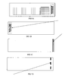
- FIGS. 1A-1D are diagrams of different imaged information occurring in different configurations on print media
- FIG 2 is a diagram of a printer, according to an example embodiment
- FIG. 3 is a diagram of another printer, according to an example embodiment
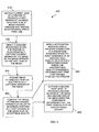
- FIG. 4 is a diagram of a method for detecting print job failures, according to an example embodiment
- FIGS. 1A-1D are diagrams of different imaged information occurring in different configurations on print media.
- the FIGS. 1A-1D are shown for purposes of illustration only. Different configurations are achievable with the teachings presented herein. Moreover, different print failure situations can be detected beyond that which is depicted in the example illustrations of the FIGS. 1A-1D .
- FIGS. 1A-1D provide a visual context that is useful in describing various aspects of the embodiments presented herein.
- FIG. 1A depicts a bar code that is printed on a first side of media. It is noted that the bar code is information that is of importance to a consumer and enterprise. The bar code uniquely identifies a particular transaction of the consumer with the enterprise that occurred in some manner.
- image refers to information, such as a bar code, unique image, unique pattern, a serial number, a pass code, etc. that a printer causes to be imaged to print media.
- the information uniquely identifies a particular transaction of a consumer with an enterprise. So, in this sense the bar code of the FIG. 1A is but one example of the type of unique identifying images that a printer can cause to be imaged to print media for purposes of the teachings presented herein and below.
- the printer is enhanced, as discussed in greater detail below, to provide automatic failure detection and correction capabilities.
- the enhanced printer can be thermal-based, inkjet-based, laser-based, and/or impact-based.
- the FIG. 1B is intended to show an opposite side of the print media depicted in the FIG. 1A , with the bar code imaged a second time as a second version or copy of the version produced in the FIG. 1B .
- the bar code is copied or duplicated on the opposite side of the media.
- the second print of the bar code occurs via a second and dual print head associated with the enhanced printer. So, a second print head reprints the bar code on an opposite side of the media.
- This bar code or unique image that is reprinted on the second side of the print media represents something that the consumer needs and therefore, the quality of the print on the first side of the media (the FIG. 1A ) needs to be of a sufficient level that the consumer can use it.
- the bar code may represent a ticket to an event that a bar code reader is going to have to scan before the consumer can enter the event. It may also be that the bar code is a boarding pass to an airplane, boat, train, etc. where a bar code reader will need to scan. Accordingly, the quality of the image appearing on the first side of the print media (the FIG. 1A barcode) needs to be of a sufficient level that it can be automatically read by scanners and/or visually read by the consumer.
- the FIG. 1C is intended to depict a solid bar code that shows no signs of image deterioration when it is printed to the first side of media.
- the FIG. 1D is intended to depict a broken or poor quality bar code that is printed to the first side of media.
- the techniques described herein and below are intended to validate that the FIG. 1C scenario is acceptable and detect that the FIG. 1D is unacceptable before media is dispensed from a printer to a consumer.
- the printer may be integrated into a kiosk that the consumer interacts with.
- the kiosk can be for a variety of purposes, such as purchasing goods, purchasing services, purchasing event tickets, and/or performing financial transactions.
- FIG 2 is a diagram of a printer 200, according to an example embodiment.
- the printer 200 can also take up other configurations and include additional components not shown in the FIG. 2 .
- the printer 200 is configured to provide automatic print failure detection and print correction.
- the printer 200 includes a first print head 210A and a capture device 220A. In some embodiments, the printer 200 also includes a second print head 210B, a second capture device 220B, and a repositioning mechanism 230. Each of these will now be discussed in turn.
- the first print head 210A is configured to produce a version of an image 201 on a first side 202 of print media 203.
- the image 201 is unique information that is being imaged on the first side 202 of the print media 203.
- This unique information can include such things as, but not limited to, a bar code, a serial number, a pass code, a unique picture, a unique design, and the like.
- the unique information identifies a transaction of a consumer with an enterprise.
- the printer 200 is a thermal printer, an inject printer, a laser printer, or an impact printer.
- the printer 200 is modified in the manner discussed herein to provide novel print failure detections and in some instances automatic corrections.
- the capture device 220A is situated and integrated within the printer 200 so as to electronically capture and record the version of the image 201 as the image 201 appears on the first side 202 of the media 203. That is, the capture device 220A is configured within and situated within the printer 200 to obtain an electronic version of the image 201 from the first side 202 of the media 203.
- the capture device 220A is also configured to verify that a quality level of the version of the image 201 is within a predefined tolerance.
- the version of the image 201 is electronically captured and verified against the predefined tolerance before the media 203 is dispensed from the printer 200 with the version of the image 201 appearing on the first side 202 of the media 203.
- the media 203 is not re-fed back through the printer to encounter the capture device 220A by the consumer of the print media 203.
- the image 201 and verification of the image 201 by the capture device 220A occur without user/consumer direction.
- the capture device 220A is a barcode reader/scanner integrated into the printer 200.
- the capture device 220A is a camera integrated into the printer 200.
- the printer 200 also includes a second print head 210B situated to interface with the media 203 on a second side 204 of the media 203.
- the second print head 210B is configured to produce another copy 205 of the image 201 on the second side 204 of the media 203.
- the printer 200 can be configured to automatically print the image 201 on the first side 202 of the media 203 using the first print head 210A and print the copy 205 on the second side 204 of the media 203; or (2) the printer 200 may just print the copy 205 on the second side 204 of the media 203 when verification of image 201 fails to be within the predefined tolerance value.
- the printer 200 may include a repositioning mechanism 230 configured to reposition the capture device 220A and/or reposition the media 203 within the printer to allow the capture device 220A to capture and record the copy 205 of the image 201, which is obtained from the second and opposite side 204 of the media 203.
- the capture device 220A also configured to verify that a second quality level for the copy 205 is within the predefined tolerance value or range of values.
- the copy 205 can be verified for quality as well by either flipping the media 203 within the printer 200 via the repositioning mechanism 230 to expose the copy 205 to the capture device 220A or by moving the capture device 220A within the printer via the repositioning mechanism 230 to read/scan the copy 205 from the second side 204.
- the printer 200 can include a second capture device 220B that is situated on the second side 204 of the media 203 and the media 203 passes through the printer 200.
- the second capture device 220B then captures and records the copy 205 and compares a second quality level for the copy 205 against the predefined threshold value or range of values.
- the second print head 210B is only activated when the first capture device 220A fails to verify the image 201 on the first side 202 of the media.
- the second print head 210B is activated regardless of the verification, such that the media 203 will always include the image 201 and the copy 205 on both the first side 202 and the second side 204.
- the capture device 220A is configured to communicate results associated with verifying the quality level over a network connection to a predefined resource.
- the results identify image attributes captured from the image 201 as the image 201 appears on the first side 202 of the media.
- the predefined resource is an email account of an administrator, a phone having a phone number of the administrator to which a text message is sent, a log database, and/or a website monitored by the administrator.
- the quality level can be any value or set of values configured within and accessible to the capture device 220A. These values can identify and/or provide a value for such things as print density, element dropouts, white areas, coloring, patterns, ability to read a provided barcode, broken lines, unbroken lines, and the like.
- the quality level is computed based on inspection of image attributes for the image 201 as it appears on the first side 202 of the media 203.
- the predefined tolerance can be a single value, a range of values, or a set of values that is compared to values obtained from the image 201, which represent the quality level, and a determination is made as to whether the image 201 is acceptable or unacceptable. So, comparing the captured image 201 from the first side 202 of the media 203 against the predefined tolerance is configured into the processing of the capture device 220A by extracting values for attributes of the image 201 and comparing those values against the predefined threshold.
- FIG. 3 is a diagram of another printer 300, according to an example embodiment.
- the printer 300 can also take up other configurations and include additional components not shown in the FIG. 3 .
- the printer 300 is configured to provide automatic print failure detection and print correction. In some cases, the printer 300 is an enhanced version or different perspective of the printer 200 discussed above with reference to the FIG. 2 .
- the printer 300 includes a first print head 301, a second print head 302, a scanner 303, and an image validation processor 304. In some cases, the printer 300 also includes a media repositioning mechanism 305. Each of these and their interactions with one another will now be discussed in turn.
- the first print head 301 is configured to interface with a first side 310 of print media 311 as that print media 311 passes through the printer 300.
- the first print head 301 is configured to produce a first version of an image 312 on the first side 310 of the media 311 as the media 311 passes through the printer 300.
- the second print head 302 is configured to interface with a second side 313 of the print media 311 as the print media 311 passes through the printer 300.
- the second print head 302 is configure to produce a second version of the image 314 on the second side 313 of the media 311 as the media 311 passes through the printer 300.
- the scanner 303 is configured to attempt to read the first version of the image 312 and pass results of the attempted read to the image validation processor 304.
- the scanner 303 is a bar code reader.
- the scanner 303 is a digital camera having processing capabilities to also read bar codes and other aspects of digital images.
- the image validation processor 304 is configured to compare the results with a threshold value to determine whether the first print head 301 has failed or is in a condition in which failure of the first print head 301 is probable on future prints to the media 311.
- the threshold value can be a single value, a set of values that map for comparison purposes to different image attribute values gleaned from the first version of the image 312 by the scanner 303, and/or a range of values. Examples of the types of attributes and values were presented above with reference to the printer 200 of the FIG. 2 .
- the image validation processor 304 is configured to report any failed comparison to a predefined resource over a network connection, such as over an Internet connection. This facilitates proactive maintenance of the printer 300 and ensures that the printer 300 is operational more frequently. It is noted that should the first print head 301 fail or start to fail, the second version of the image 314 is still available to a consumer on the second side 313 of the media 311. So, the printer 300 remains operational while a service call goes out to fix the first print head 301 and that service call can be automatically generated by the image validation processor 304.
- the printer 300 also includes a media repositioning mechanism 305.
- the media repositioning mechanism 305 is configured to reposition the second side 313 of the media 311 so that the second side 313 is exposed to the scanner 303 for the second version of the image 314 to be validated by the image validation processor 304 when the results do not meet the threshold value.
- the repositioning mechanism 305 moves the second side 313 of the media 311 having the second version of the image 314 to the scanner 303 to capture an electronic copy of that second version of the image 314 and supplies that to the image validation processor 304 for validation when the first version of the image 312 is defective. This provides two checks of the image to make sure at least one of the print heads 301 or 302 is functioning properly for a consumer.
- the printer 300 is: a dual-sided thermal printer, a dual-sided laser printer, a dual-sided inkjet printer, or a dual-sided impact printer.
- the printer 300 may also be part of or integrated into a standalone consumer kiosk.
- FIG. 4 is a diagram of a method 400 for detecting print job failures, according to an example embodiment.
- the method 400 (hereinafter referred to as "print service") is implemented in and programmed within a non-transitory processor-readable storage medium and is executed by one or more processors embedded within a printer.
- the printers 200 and 300 of the FIGS. 2 and 3 are capable of processing the print service.
- the print service instructs a print head of a printer to produce a first version of an image on a first side of media passing through the printer in accordance with a print job.
- the image is some uniquely identifying information that uniquely identifies a transaction of a consumer with an enterprise, such as a bar code, a unique pattern, a pass code, and the like.
- the print service directs a scanner that is integrated within the printer to electronically capture the first version of the image as the image appears on the first side of the media. So, the scanner acquires an electronic version of the image from the media after the image is produced on the media.
- the print service acquires image attributes from the electronically captured version of the image. Examples of the types of image attributes and values were provided above with reference to the FIGS. 2 and 3 .
- the print service compares the image attributes against threshold values to determine whether the first version of the image is of an acceptable quality. Again, what is "acceptable” can be defined via threshold values that are compared against the image attributes acquired from the image as it appears on the media. This was discussed at length above with reference to the FIGS. 2 and 3 .
- the print service activates a second print head to produce a second version of the image on a second side of the media when the comparison determines that the first version is of an unacceptable quality. So, the image is reproduced on the opposite side of the media when the original produced image on the first side fails to meet a predefined quality level.
- the print service sends a notification message over a network connection to a predefined resource when the first version is of an unacceptable quality or is within a predefined range where the unacceptable quality is probable or subsequent print jobs passing through the printer.
- the print service can decide that unacceptable quality is probable with future print jobs and can remotely request service to replace the first print head in advance of its failure.
Landscapes
- Physics & Mathematics (AREA)
- General Physics & Mathematics (AREA)
- Engineering & Computer Science (AREA)
- Theoretical Computer Science (AREA)
- Accessory Devices And Overall Control Thereof (AREA)
- Record Information Processing For Printing (AREA)
- Printers Characterized By Their Purpose (AREA)
- Dot-Matrix Printers And Others (AREA)
Abstract
Description
- Thermal printing has always held the downside of the fact that print head deterioration as well as poor thermal paper quality can result in poor print quality, which can lead to a number of downstream issues and problems. These problems include the failure to be able to read the intended printed information, which can often include bar codes that are read by scanners as part of the process. Failure of these bar codes or other information to print correctly and as a result be non-readable, disrupts the intended process flow and results in potentially significant disruptions, requiring intensive actions to resolve.
- The situation is often made worse as many thermal printing operations are unmanned allowing for the problem to persist for an extended period of time before being identified and only after process interruptions have occurred. This magnifies the seriousness of the problem created and increases the required effort to correct.
- The identified problems, associated with printing bar codes and other critical information, are not limited to thermal printers. That is, ink jet printers, impact printers, and laser printers also have similar issues, which are: unmanned printing stations can malfunction for an extended period of time before the problems are detected and corrected; such situations are costly to enterprises.
- In various embodiments, techniques for automatic print failure detection and correction are presented. According to an embodiment, a printer is presented. The printer includes a print head and a capture device. The capture device is situated within the printer for purposes of electronically capturing and recording the version of the image, which is obtained from the first side of the media. The capture device is also configured for verifying that a quality level of the version is within a predefined tolerance; the version is electronically captured and verified before the media is dispensed from the printer with the version of the image appearing on the first side of the media.
- According to a first aspect there is provided a printer, comprising: a print head configured to produce a version of an image on a first side of media; and a capture device situated within the printer to electronically capture and record the version of the image obtained from the first side of the media and configured to verify that a quality level of the version is within a predefined tolerance, the version is electronically captured and verified before the media is dispensed from the printer with the version of the image on the first side of the media.
- According to a second aspect of the invention there is provided a processor-implemented method programmed in a non-transitory computer-readable medium and executed by a processor embedded in a printer, comprising: instructing a print head of a printer to produce a first version of an image on a first side of media passing through the printer in accordance with a print job; directing a scanner integrated within the printer to electronically capture the first version of the image as the image appears on the first side of the media; acquiring image attributes from the electronically captured version of the image; and comparing the image attributes against threshold values to determine whether the first version of the image is of an acceptable quality.
- According to a third aspect of the invention there is provided a printer, comprising: a first print head; a second print head; a scanner; and an image validation processor, the first print head configured to produce a first version of an image on a first side of media passing through the printer, and the second print head configured to produce a second version of the image on a second side of the media as the media passes through the printer, and the scanner configured to attempt to read the first version of the image and pass results of the attempted read to the image validation processor, the image validation processor configured to compare the results with a threshold value to determine whether the first print head has failed or is in a condition in which failure of the first print head is probable on future prints to other media.
- The printer may be a dual-sided thermal printer, a dual-sided laser printer, a dual-sided inkjet printer, or a dual-sided impact printer.
- The printer may comprise a standalone consumer kiosk.
- The printer may further comprise a media repositioning mechanism configured to reposition the second side of the media to be exposed to the scanner for the second version of the image to be validated by the image validation processor when the results do not meet the threshold value
- The image validation processor may be configured to report any failed comparison to a predefined resource over a network connection.
- These and other aspects of the invention will be apparent from the following specific description, given by way of example, with reference to the accompanying drawings, in which:
-
FIGS. 1A-1D are diagrams of different imaged information occurring in different configurations on print media; -
FIG 2 . is a diagram of a printer, according to an example embodiment; -
FIG. 3 is a diagram of another printer, according to an example embodiment; -
FIG. 4 is a diagram of a method for detecting print job failures, according to an example embodiment; -
FIGS. 1A-1D are diagrams of different imaged information occurring in different configurations on print media. TheFIGS. 1A-1D are shown for purposes of illustration only. Different configurations are achievable with the teachings presented herein. Moreover, different print failure situations can be detected beyond that which is depicted in the example illustrations of theFIGS. 1A-1D . - The
FIGS. 1A-1D provide a visual context that is useful in describing various aspects of the embodiments presented herein. - For example, the
FIG. 1A depicts a bar code that is printed on a first side of media. It is noted that the bar code is information that is of importance to a consumer and enterprise. The bar code uniquely identifies a particular transaction of the consumer with the enterprise that occurred in some manner. - As used herein "image" refers to information, such as a bar code, unique image, unique pattern, a serial number, a pass code, etc. that a printer causes to be imaged to print media. The information uniquely identifies a particular transaction of a consumer with an enterprise. So, in this sense the bar code of the
FIG. 1A is but one example of the type of unique identifying images that a printer can cause to be imaged to print media for purposes of the teachings presented herein and below. - The printer is enhanced, as discussed in greater detail below, to provide automatic failure detection and correction capabilities. The enhanced printer can be thermal-based, inkjet-based, laser-based, and/or impact-based.
- The
FIG. 1B is intended to show an opposite side of the print media depicted in theFIG. 1A , with the bar code imaged a second time as a second version or copy of the version produced in theFIG. 1B . Essentially, the bar code is copied or duplicated on the opposite side of the media. As will be discussed in greater detail herein and below, the second print of the bar code occurs via a second and dual print head associated with the enhanced printer. So, a second print head reprints the bar code on an opposite side of the media. - This bar code or unique image that is reprinted on the second side of the print media (can be referred to as "media" herein and below) represents something that the consumer needs and therefore, the quality of the print on the first side of the media (the
FIG. 1A ) needs to be of a sufficient level that the consumer can use it. For example, the bar code may represent a ticket to an event that a bar code reader is going to have to scan before the consumer can enter the event. It may also be that the bar code is a boarding pass to an airplane, boat, train, etc. where a bar code reader will need to scan. Accordingly, the quality of the image appearing on the first side of the print media (theFIG. 1A barcode) needs to be of a sufficient level that it can be automatically read by scanners and/or visually read by the consumer. - The
FIG. 1C is intended to depict a solid bar code that shows no signs of image deterioration when it is printed to the first side of media. Conversely, theFIG. 1D is intended to depict a broken or poor quality bar code that is printed to the first side of media. The techniques described herein and below are intended to validate that theFIG. 1C scenario is acceptable and detect that theFIG. 1D is unacceptable before media is dispensed from a printer to a consumer. - It is also noted that, in some embodiments, the printer may be integrated into a kiosk that the consumer interacts with. The kiosk can be for a variety of purposes, such as purchasing goods, purchasing services, purchasing event tickets, and/or performing financial transactions.
- It is within this context that various embodiments of the invention are now presented.
-
FIG 2 . is a diagram of aprinter 200, according to an example embodiment. Theprinter 200 can also take up other configurations and include additional components not shown in theFIG. 2 . Theprinter 200 is configured to provide automatic print failure detection and print correction. - The
printer 200 includes afirst print head 210A and acapture device 220A. In some embodiments, theprinter 200 also includes asecond print head 210B, asecond capture device 220B, and arepositioning mechanism 230. Each of these will now be discussed in turn. - The
first print head 210A is configured to produce a version of animage 201 on afirst side 202 ofprint media 203. Again, theimage 201 is unique information that is being imaged on thefirst side 202 of theprint media 203. This unique information can include such things as, but not limited to, a bar code, a serial number, a pass code, a unique picture, a unique design, and the like. The unique information identifies a transaction of a consumer with an enterprise. - According to an embodiment, the
printer 200 is a thermal printer, an inject printer, a laser printer, or an impact printer. Theprinter 200 is modified in the manner discussed herein to provide novel print failure detections and in some instances automatic corrections. - The
capture device 220A is situated and integrated within theprinter 200 so as to electronically capture and record the version of theimage 201 as theimage 201 appears on thefirst side 202 of themedia 203. That is, thecapture device 220A is configured within and situated within theprinter 200 to obtain an electronic version of theimage 201 from thefirst side 202 of themedia 203. - The
capture device 220A is also configured to verify that a quality level of the version of theimage 201 is within a predefined tolerance. - It is noted that the version of the
image 201 is electronically captured and verified against the predefined tolerance before themedia 203 is dispensed from theprinter 200 with the version of theimage 201 appearing on thefirst side 202 of themedia 203. In other words, themedia 203 is not re-fed back through the printer to encounter thecapture device 220A by the consumer of theprint media 203. Theimage 201 and verification of theimage 201 by thecapture device 220A occur without user/consumer direction. - In an embodiment, the
capture device 220A is a barcode reader/scanner integrated into theprinter 200. - In another scenario, the
capture device 220A is a camera integrated into theprinter 200. - According to one configuration, the
printer 200 also includes asecond print head 210B situated to interface with themedia 203 on asecond side 204 of themedia 203. Thesecond print head 210B is configured to produce anothercopy 205 of theimage 201 on thesecond side 204 of themedia 203. - Depending on parameters associated with the print job that the
printer 200 is processing to produce theimage 201, (1) theprinter 200 can be configured to automatically print theimage 201 on thefirst side 202 of themedia 203 using thefirst print head 210A and print thecopy 205 on thesecond side 204 of themedia 203; or (2) theprinter 200 may just print thecopy 205 on thesecond side 204 of themedia 203 when verification ofimage 201 fails to be within the predefined tolerance value. - So, in one case, the
printer 200 may include arepositioning mechanism 230 configured to reposition thecapture device 220A and/or reposition themedia 203 within the printer to allow thecapture device 220A to capture and record thecopy 205 of theimage 201, which is obtained from the second andopposite side 204 of themedia 203. Thecapture device 220A also configured to verify that a second quality level for thecopy 205 is within the predefined tolerance value or range of values. Thus, thecopy 205 can be verified for quality as well by either flipping themedia 203 within theprinter 200 via therepositioning mechanism 230 to expose thecopy 205 to thecapture device 220A or by moving thecapture device 220A within the printer via therepositioning mechanism 230 to read/scan thecopy 205 from thesecond side 204. - Another configuration of the
printer 200 can occur as well as an alternative to the last embodiment discussed. For example, theprinter 200 can include asecond capture device 220B that is situated on thesecond side 204 of themedia 203 and themedia 203 passes through theprinter 200. Thesecond capture device 220B then captures and records thecopy 205 and compares a second quality level for thecopy 205 against the predefined threshold value or range of values. - In some situations, the
second print head 210B is only activated when thefirst capture device 220A fails to verify theimage 201 on thefirst side 202 of the media. - In other cases, the
second print head 210B is activated regardless of the verification, such that themedia 203 will always include theimage 201 and thecopy 205 on both thefirst side 202 and thesecond side 204. - According to an embodiment, the
capture device 220A is configured to communicate results associated with verifying the quality level over a network connection to a predefined resource. In some cases, the results identify image attributes captured from theimage 201 as theimage 201 appears on thefirst side 202 of the media. - In an embodiment, the predefined resource is an email account of an administrator, a phone having a phone number of the administrator to which a text message is sent, a log database, and/or a website monitored by the administrator.
- It is noted that the quality level can be any value or set of values configured within and accessible to the
capture device 220A. These values can identify and/or provide a value for such things as print density, element dropouts, white areas, coloring, patterns, ability to read a provided barcode, broken lines, unbroken lines, and the like. The quality level is computed based on inspection of image attributes for theimage 201 as it appears on thefirst side 202 of themedia 203. The predefined tolerance can be a single value, a range of values, or a set of values that is compared to values obtained from theimage 201, which represent the quality level, and a determination is made as to whether theimage 201 is acceptable or unacceptable. So, comparing the capturedimage 201 from thefirst side 202 of themedia 203 against the predefined tolerance is configured into the processing of thecapture device 220A by extracting values for attributes of theimage 201 and comparing those values against the predefined threshold. -
FIG. 3 is a diagram of anotherprinter 300, according to an example embodiment. Theprinter 300 can also take up other configurations and include additional components not shown in theFIG. 3 . Theprinter 300 is configured to provide automatic print failure detection and print correction. In some cases, theprinter 300 is an enhanced version or different perspective of theprinter 200 discussed above with reference to theFIG. 2 . - The
printer 300 includes afirst print head 301, asecond print head 302, ascanner 303, and animage validation processor 304. In some cases, theprinter 300 also includes amedia repositioning mechanism 305. Each of these and their interactions with one another will now be discussed in turn. - The
first print head 301 is configured to interface with afirst side 310 ofprint media 311 as thatprint media 311 passes through theprinter 300. Thefirst print head 301 is configured to produce a first version of animage 312 on thefirst side 310 of themedia 311 as themedia 311 passes through theprinter 300. - The
second print head 302 is configured to interface with asecond side 313 of theprint media 311 as theprint media 311 passes through theprinter 300. Thesecond print head 302 is configure to produce a second version of theimage 314 on thesecond side 313 of themedia 311 as themedia 311 passes through theprinter 300. - The
scanner 303 is configured to attempt to read the first version of theimage 312 and pass results of the attempted read to theimage validation processor 304. - According to an embodiment, the
scanner 303 is a bar code reader. In another case, thescanner 303 is a digital camera having processing capabilities to also read bar codes and other aspects of digital images. - The
image validation processor 304 is configured to compare the results with a threshold value to determine whether thefirst print head 301 has failed or is in a condition in which failure of thefirst print head 301 is probable on future prints to themedia 311. - The threshold value can be a single value, a set of values that map for comparison purposes to different image attribute values gleaned from the first version of the
image 312 by thescanner 303, and/or a range of values. Examples of the types of attributes and values were presented above with reference to theprinter 200 of theFIG. 2 . - In an embodiment, the
image validation processor 304 is configured to report any failed comparison to a predefined resource over a network connection, such as over an Internet connection. This facilitates proactive maintenance of theprinter 300 and ensures that theprinter 300 is operational more frequently. It is noted that should thefirst print head 301 fail or start to fail, the second version of theimage 314 is still available to a consumer on thesecond side 313 of themedia 311. So, theprinter 300 remains operational while a service call goes out to fix thefirst print head 301 and that service call can be automatically generated by theimage validation processor 304. - According to an embodiment, the
printer 300 also includes amedia repositioning mechanism 305. Themedia repositioning mechanism 305 is configured to reposition thesecond side 313 of themedia 311 so that thesecond side 313 is exposed to thescanner 303 for the second version of theimage 314 to be validated by theimage validation processor 304 when the results do not meet the threshold value. In other words, therepositioning mechanism 305 moves thesecond side 313 of themedia 311 having the second version of theimage 314 to thescanner 303 to capture an electronic copy of that second version of theimage 314 and supplies that to theimage validation processor 304 for validation when the first version of theimage 312 is defective. This provides two checks of the image to make sure at least one of the print heads 301 or 302 is functioning properly for a consumer. - In some cases, the
printer 300 is: a dual-sided thermal printer, a dual-sided laser printer, a dual-sided inkjet printer, or a dual-sided impact printer. - The
printer 300 may also be part of or integrated into a standalone consumer kiosk. -
FIG. 4 is a diagram of amethod 400 for detecting print job failures, according to an example embodiment. The method 400 (hereinafter referred to as "print service") is implemented in and programmed within a non-transitory processor-readable storage medium and is executed by one or more processors embedded within a printer. Theprinters FIGS. 2 and3 are capable of processing the print service. - At 410, the print service instructs a print head of a printer to produce a first version of an image on a first side of media passing through the printer in accordance with a print job. The image is some uniquely identifying information that uniquely identifies a transaction of a consumer with an enterprise, such as a bar code, a unique pattern, a pass code, and the like.
- At 420, the print service directs a scanner that is integrated within the printer to electronically capture the first version of the image as the image appears on the first side of the media. So, the scanner acquires an electronic version of the image from the media after the image is produced on the media.
- At 430, the print service acquires image attributes from the electronically captured version of the image. Examples of the types of image attributes and values were provided above with reference to the
FIGS. 2 and3 . - At 440, the print service compares the image attributes against threshold values to determine whether the first version of the image is of an acceptable quality. Again, what is "acceptable" can be defined via threshold values that are compared against the image attributes acquired from the image as it appears on the media. This was discussed at length above with reference to the
FIGS. 2 and3 . - According to an embodiment, at 450, the print service activates a second print head to produce a second version of the image on a second side of the media when the comparison determines that the first version is of an unacceptable quality. So, the image is reproduced on the opposite side of the media when the original produced image on the first side fails to meet a predefined quality level.
- In another situation, at 460, the print service sends a notification message over a network connection to a predefined resource when the first version is of an unacceptable quality or is within a predefined range where the unacceptable quality is probable or subsequent print jobs passing through the printer. In other words, when image attribute values are approaching a threshold and appear within a predefined range, the print service can decide that unacceptable quality is probable with future print jobs and can remotely request service to replace the first print head in advance of its failure.
- The above description is illustrative, and not restrictive. Many other embodiments will be apparent to those of skill in the art upon reviewing the above description. The scope of embodiments should therefore be determined with reference to the appended claims, along with the full scope of equivalents to which such claims are entitled.
- In the foregoing description of the embodiments, various features are grouped together in a single embodiment for the purpose of streamlining the disclosure. Various modifications may be made to the above embodiments within the scope of the present invention.
Claims (15)
- A printer (200 or 300) comprising:a print head (210A or 301) configured to produce a version of an image (201 or 312) on a first side (202 or 310) of media (203 or 311); anda capture device (220A or (303) situated within the printer (200 or 300) to electronically capture and record the version of the image (201 or 312) obtained from the first side (202 or 310) of the media (203 or 311) and configured to verify that a quality level of the version is within a predefined tolerance, the version being electronically captured and verified before the media (203 or 311) is dispensed from the printer (200 or 300) with the version of the image (201 or 312) on the first side (202 or 310) of the media (203 or 311).
- The printer of claim 1, wherein the printer (200 or 300) is one of: a thermal printer, an inkjet printer, a laser printer, and an impact printer.
- The printer of claim 1 or 2, wherein the capture device (220A or 303) is a barcode reader integrated into the printer (200 or 300).
- The printer of claim 1 or 2, wherein the capture device (220A or 303) is a camera integrated into the printer (200 or 300).
- The printer of any preceding claim, further comprising a second print head (210B or 302) configured to produce another copy of the image (205 or 314) on a second and opposite side (204 or 313) of the media (203 or 311).
- The printer of claim 5, further comprising a repositioning mechanism (230 or 305) configured to reposition the capture device (220A or 303) and/or to reposition the media (203 or 311) within the printer (200 or 300) to allow the capture device (220A or 303) to capture and record the copy of the image (205 or 314) obtained from the second and opposite side (204 or 313) of the media (203 or 311), the capture device (220A or 303) being configured to verify that a second quality level for the copy (205 or 314) is within the predefined tolerance.
- The printer of claim 5 further comprising: a second capture device (220B) configured to capture and record the copy (205 or 314) obtained from the second and opposite side (204 or 313) of the media (203 or 311), the second capture device (220B) being configured to verify that a second quality level for the copy (205 or 314) is within the predefined tolerance.
- The printer of claim 5, wherein the second print head (210B or 302) is configured to be activated when the capture device (220A or 303) fails to verify the quality level to be within the predefined tolerance.
- The printer of claim 5, wherein the second print head (210B or 302) is configured to be activated regardless of results associated with verifying the quality level to the predefined tolerance.
- The printer of any preceding claim, wherein the capture device (220A or 303) is configured to communicate results associated with verifying the quality level over a network connection to a predefined resource.
- The printer of claim 10, wherein the predefined resource is at least one of: an email account of an administrator, a text message to a predefined phone number of the administrator, a log database, and a website monitored by the administrator.
- The printer of claim 10 or 11, wherein the results identify image attributes captured from the image (201 or 312) as the image (201 or 312) appears on the first side (202 or 310) of the media (203 or 311).
- A processor-implemented method programmed in a non-transitory computer-readable medium and executed by a processor embedded in a printer (200 or 300), comprising:instructing a print head (210A or 301) of a printer (200 or 300) to produce a first version of an image (201 or 312) on a first side (202 or 310) of media (203 or 311) passing through the printer (200 or 300) in accordance with a print job;directing a scanner (220A or 303) integrated within the printer (200 or 300) to electronically capture the first version of the image (201 or 312) as the image appears on the first side (202 or 310) of the media (203 or 311);acquiring image attributes from the electronically captured version of the image (201 or 312); andcomparing the image attributes against threshold values to determine whether the first version of the image (201 or 312) is of an acceptable quality.
- The method of claim 13, further comprising activating a second print head (210B or 302) to produce a second version of the image (205 or 314) on a second side (204 or 313) of the media (203 or 311) when the comparison determines that the first version (201 or 312) is of an unacceptable quality.
- The method of claim 13 or 14 further comprising, sending a notification message over a network connection to a predefined resource when the first version (201 or 312) is of an unacceptable quality or is within a predefined range where the unacceptable quality is probable on subsequent print jobs passing through the printer (200 or 300).
Applications Claiming Priority (1)
| Application Number | Priority Date | Filing Date | Title |
|---|---|---|---|
| US12/924,084 US8879085B2 (en) | 2010-09-20 | 2010-09-20 | Automatic print failure detection and correction |
Publications (2)
| Publication Number | Publication Date |
|---|---|
| EP2431186A1 true EP2431186A1 (en) | 2012-03-21 |
| EP2431186B1 EP2431186B1 (en) | 2014-01-08 |
Family
ID=44772728
Family Applications (1)
| Application Number | Title | Priority Date | Filing Date |
|---|---|---|---|
| EP11178197.7A Not-in-force EP2431186B1 (en) | 2010-09-20 | 2011-08-19 | Automatic Print Failure Detection and Correction |
Country Status (3)
| Country | Link |
|---|---|
| US (1) | US8879085B2 (en) |
| EP (1) | EP2431186B1 (en) |
| JP (1) | JP5921842B2 (en) |
Cited By (2)
| Publication number | Priority date | Publication date | Assignee | Title |
|---|---|---|---|---|
| EP2770426A3 (en) * | 2013-02-25 | 2015-01-21 | Ricoh Company, Ltd. | Writing apparatus, writing system, and writing method |
| CN106767991A (en) * | 2017-02-27 | 2017-05-31 | 国网山东省电力公司电力科学研究院 | A kind of Thermal Meter verification management system and method based on WLAN |
Families Citing this family (7)
| Publication number | Priority date | Publication date | Assignee | Title |
|---|---|---|---|---|
| US20110135144A1 (en) * | 2009-07-01 | 2011-06-09 | Hand Held Products, Inc. | Method and system for collecting voice and image data on a remote device and coverting the combined data |
| JP6379832B2 (en) * | 2014-08-07 | 2018-08-29 | 富士ゼロックス株式会社 | Facsimile maintenance system and program |
| WO2017011005A1 (en) | 2015-07-15 | 2017-01-19 | Hewlett-Packard Development Company, L.P. | Diagnostic plot for printing system |
| US10795618B2 (en) | 2018-01-05 | 2020-10-06 | Datamax-O'neil Corporation | Methods, apparatuses, and systems for verifying printed image and improving print quality |
| US10546160B2 (en) | 2018-01-05 | 2020-01-28 | Datamax-O'neil Corporation | Methods, apparatuses, and systems for providing print quality feedback and controlling print quality of machine-readable indicia |
| US10803264B2 (en) | 2018-01-05 | 2020-10-13 | Datamax-O'neil Corporation | Method, apparatus, and system for characterizing an optical system |
| US10834283B2 (en) | 2018-01-05 | 2020-11-10 | Datamax-O'neil Corporation | Methods, apparatuses, and systems for detecting printing defects and contaminated components of a printer |
Citations (7)
| Publication number | Priority date | Publication date | Assignee | Title |
|---|---|---|---|---|
| JPS637955A (en) * | 1986-06-30 | 1988-01-13 | Pfu Ltd | Bar code printing system |
| JPH02225074A (en) * | 1989-02-27 | 1990-09-07 | Matsushita Electric Ind Co Ltd | Bar code printer |
| JPH0478551A (en) * | 1990-07-20 | 1992-03-12 | Nec Corp | Barcode printing device |
| JPH05307627A (en) * | 1991-09-18 | 1993-11-19 | Nippondenso Co Ltd | Bar code terminal equipment |
| US5564841A (en) * | 1994-09-13 | 1996-10-15 | Intermec Corporation | System and method for dynamic adjustment of bar code printer parameters |
| JP2002216070A (en) * | 2001-01-15 | 2002-08-02 | Dainippon Printing Co Ltd | Barcode inspection device |
| US20100060708A1 (en) * | 2008-09-08 | 2010-03-11 | Toshiba Tec Kabushiki Kaisha | Thermal printer and method of controlling the same |
Family Cites Families (27)
| Publication number | Priority date | Publication date | Assignee | Title |
|---|---|---|---|---|
| JP3634419B2 (en) * | 1994-07-25 | 2005-03-30 | セイコーエプソン株式会社 | Image processing method and image processing apparatus |
| JP2866340B2 (en) * | 1996-03-08 | 1999-03-08 | エヌオーケーイージーアンドジーオプトエレクトロニクス株式会社 | Printer device and print processing device |
| US7733522B2 (en) * | 1997-12-30 | 2010-06-08 | Imagetag, Inc. | Apparatus and method for optimized facsimile transmission |
| JPH11254793A (en) * | 1998-03-09 | 1999-09-21 | Chescom International Kk | Printer system and printer device |
| US6045046A (en) * | 1998-08-27 | 2000-04-04 | Ncr Corporation | Full coverage barcode scanner |
| US6448979B1 (en) * | 1999-01-25 | 2002-09-10 | Airclic, Inc. | Printed medium activated interactive communication of multimedia information, including advertising |
| US6710895B1 (en) * | 1999-11-16 | 2004-03-23 | Cyberscan Technology, Inc. | Compact configurable scanning computer terminal |
| US6650427B2 (en) * | 2001-06-01 | 2003-11-18 | Transact Technologies Incorporated | Self validating printer with ticket voiding features |
| NL1018512C1 (en) * | 2001-07-11 | 2001-11-02 | Beheermij Van Der Loo B V | Automatic cash register system. |
| EP1380982A1 (en) * | 2002-07-08 | 2004-01-14 | Sicpa Holding S.A. | Method and device for coding articles |
| US7080779B2 (en) * | 2002-07-26 | 2006-07-25 | Automark Technical Systems, Llc | Ballot marking system and apparatus |
| JP2004160981A (en) * | 2002-09-20 | 2004-06-10 | Tohoku Ricoh Co Ltd | Mark seal printing/inspection device, printed mark seal inspecting method and mark seal printing control method |
| US7344078B2 (en) * | 2002-12-05 | 2008-03-18 | Riocoh Co., Ltd. | Device for scanning and printing barcodes |
| JP2004326624A (en) * | 2003-04-25 | 2004-11-18 | Aruze Corp | Identification sensor |
| JP4396165B2 (en) * | 2003-07-09 | 2010-01-13 | 富士ゼロックス株式会社 | Print processing apparatus, program, and information leakage prevention method |
| DE102004014547B4 (en) * | 2004-03-23 | 2010-06-10 | Koenig & Bauer Aktiengesellschaft | Method for the early detection of a deviation in printed images produced by a printing machine of an ongoing production |
| US7077314B2 (en) * | 2004-03-31 | 2006-07-18 | Oracle International Corporation | Methods and systems for voter-verified secure electronic voting |
| JP4538845B2 (en) * | 2004-04-21 | 2010-09-08 | 富士ゼロックス株式会社 | FAILURE DIAGNOSIS METHOD, FAILURE DIAGNOSIS DEVICE, IMAGE FORMING DEVICE, PROGRAM, AND STORAGE MEDIUM |
| JP4804043B2 (en) * | 2005-06-03 | 2011-10-26 | キヤノン株式会社 | Inkjet recording apparatus, inkjet recording method, and recording control mode setting method |
| US20060289633A1 (en) * | 2005-06-23 | 2006-12-28 | Ncr Corporation | Receipts having dual-sided thermal printing |
| US8721202B2 (en) * | 2005-12-08 | 2014-05-13 | Ncr Corporation | Two-sided thermal print switch |
| US8670009B2 (en) * | 2006-03-07 | 2014-03-11 | Ncr Corporation | Two-sided thermal print sensing |
| DE102006015828A1 (en) * | 2006-04-03 | 2007-10-04 | Man Roland Druckmaschinen Ag | Image inspection system for e.g. sheet-fed offset press, has sorting device, where data, which are stored in memory and obtained by image processing algorithm, are stored in another memory for analysis by algorithm |
| US20080079763A1 (en) * | 2006-09-29 | 2008-04-03 | Weyerhaeuser Co. | Systems And Methods For Verifying The Operational Conditions Of Print Heads in a Digital Printing Environment |
| US7802725B1 (en) * | 2006-12-18 | 2010-09-28 | Ncr Corporation | Customizing security features |
| US8144936B2 (en) * | 2007-12-05 | 2012-03-27 | Bell And Howell, Llc | Camera based ink application verification |
| JP2010151606A (en) * | 2008-12-25 | 2010-07-08 | Ricoh Co Ltd | Image inspecting apparatus, image inspection method and program |
-
2010
- 2010-09-20 US US12/924,084 patent/US8879085B2/en not_active Expired - Fee Related
-
2011
- 2011-08-19 EP EP11178197.7A patent/EP2431186B1/en not_active Not-in-force
- 2011-09-20 JP JP2011204158A patent/JP5921842B2/en not_active Expired - Fee Related
Patent Citations (7)
| Publication number | Priority date | Publication date | Assignee | Title |
|---|---|---|---|---|
| JPS637955A (en) * | 1986-06-30 | 1988-01-13 | Pfu Ltd | Bar code printing system |
| JPH02225074A (en) * | 1989-02-27 | 1990-09-07 | Matsushita Electric Ind Co Ltd | Bar code printer |
| JPH0478551A (en) * | 1990-07-20 | 1992-03-12 | Nec Corp | Barcode printing device |
| JPH05307627A (en) * | 1991-09-18 | 1993-11-19 | Nippondenso Co Ltd | Bar code terminal equipment |
| US5564841A (en) * | 1994-09-13 | 1996-10-15 | Intermec Corporation | System and method for dynamic adjustment of bar code printer parameters |
| JP2002216070A (en) * | 2001-01-15 | 2002-08-02 | Dainippon Printing Co Ltd | Barcode inspection device |
| US20100060708A1 (en) * | 2008-09-08 | 2010-03-11 | Toshiba Tec Kabushiki Kaisha | Thermal printer and method of controlling the same |
Cited By (4)
| Publication number | Priority date | Publication date | Assignee | Title |
|---|---|---|---|---|
| EP2770426A3 (en) * | 2013-02-25 | 2015-01-21 | Ricoh Company, Ltd. | Writing apparatus, writing system, and writing method |
| US9280690B2 (en) | 2013-02-25 | 2016-03-08 | Ricoh Company, Limited | Writing apparatus, writing system, and writing method |
| CN106767991A (en) * | 2017-02-27 | 2017-05-31 | 国网山东省电力公司电力科学研究院 | A kind of Thermal Meter verification management system and method based on WLAN |
| CN106767991B (en) * | 2017-02-27 | 2019-11-19 | 国网山东省电力公司电力科学研究院 | A thermal instrument verification management system and method based on wireless local area network |
Also Published As
| Publication number | Publication date |
|---|---|
| US8879085B2 (en) | 2014-11-04 |
| JP2012061858A (en) | 2012-03-29 |
| EP2431186B1 (en) | 2014-01-08 |
| US20120069378A1 (en) | 2012-03-22 |
| JP5921842B2 (en) | 2016-05-24 |
Similar Documents
| Publication | Publication Date | Title |
|---|---|---|
| EP2431186B1 (en) | Automatic Print Failure Detection and Correction | |
| JP6295561B2 (en) | Image inspection result determination apparatus, image inspection system, and image inspection result determination method | |
| US20230041346A1 (en) | Methods, apparatuses, and systems for providing print quality feedback and controlling print quality of machine readable indicia | |
| CN111089867B (en) | Image inspection device and recording medium | |
| US6912674B2 (en) | System and method for diagnosing printer problems and notarizing prints by evaluating embedded data | |
| US10545844B2 (en) | Print verification system that reports defective printheads | |
| US20180063339A1 (en) | Image forming apparatus and image forming system | |
| US20230067117A1 (en) | Inspection apparatus, method, and non-transitory storage medium for inspecting print product | |
| JP5845926B2 (en) | Printing apparatus and printing apparatus control method | |
| CN104070861B (en) | The leak source detection method of image processing apparatus and image processing apparatus | |
| JP6438184B2 (en) | System having function of verifying consistency with expected print output, and method of verification | |
| JP7844185B2 (en) | Inspection equipment, inspection methods, printing systems, inspection systems | |
| US9507547B1 (en) | Special processing indicators for print verification systems | |
| JP4853050B2 (en) | Print management apparatus, program, and method | |
| JP2005205687A (en) | Printing inspection device and method | |
| US20100238462A1 (en) | System and method for image quality analysis and diagnostics | |
| JP7559314B2 (en) | Dynamic scan quality control management for print jobs | |
| JP2005043235A (en) | Device and program for inspecting printed matter | |
| US10204353B2 (en) | Copy detection using extinsic features | |
| US8693062B2 (en) | Facsimile service support device, system, and method | |
| US10926563B2 (en) | Ink jet printing apparatus, control method thereof and storage medium | |
| JP2001277676A (en) | Printed matter inspection apparatus, printed matter inspection system, printed matter inspection method, and storage medium | |
| JP2012160976A (en) | Image processing system, printing method, program, and record medium | |
| EP4046810A1 (en) | Dynamic scan quality control management for print jobs | |
| JP2009143004A (en) | Printing test method/device |
Legal Events
| Date | Code | Title | Description |
|---|---|---|---|
| PUAI | Public reference made under article 153(3) epc to a published international application that has entered the european phase |
Free format text: ORIGINAL CODE: 0009012 |
|
| AK | Designated contracting states |
Kind code of ref document: A1 Designated state(s): AL AT BE BG CH CY CZ DE DK EE ES FI FR GB GR HR HU IE IS IT LI LT LU LV MC MK MT NL NO PL PT RO RS SE SI SK SM TR |
|
| AX | Request for extension of the european patent |
Extension state: BA ME |
|
| 17P | Request for examination filed |
Effective date: 20120921 |
|
| GRAP | Despatch of communication of intention to grant a patent |
Free format text: ORIGINAL CODE: EPIDOSNIGR1 |
|
| GRAS | Grant fee paid |
Free format text: ORIGINAL CODE: EPIDOSNIGR3 |
|
| INTG | Intention to grant announced |
Effective date: 20131113 |
|
| GRAA | (expected) grant |
Free format text: ORIGINAL CODE: 0009210 |
|
| AK | Designated contracting states |
Kind code of ref document: B1 Designated state(s): AL AT BE BG CH CY CZ DE DK EE ES FI FR GB GR HR HU IE IS IT LI LT LU LV MC MK MT NL NO PL PT RO RS SE SI SK SM TR |
|
| REG | Reference to a national code |
Ref country code: GB Ref legal event code: FG4D |
|
| REG | Reference to a national code |
Ref country code: CH Ref legal event code: EP |
|
| REG | Reference to a national code |
Ref country code: IE Ref legal event code: FG4D |
|
| REG | Reference to a national code |
Ref country code: AT Ref legal event code: REF Ref document number: 648458 Country of ref document: AT Kind code of ref document: T Effective date: 20140215 |
|
| REG | Reference to a national code |
Ref country code: DE Ref legal event code: R096 Ref document number: 602011004541 Country of ref document: DE Effective date: 20140220 |
|
| REG | Reference to a national code |
Ref country code: DE Ref legal event code: R084 Ref document number: 602011004541 Country of ref document: DE Effective date: 20140120 |
|
| REG | Reference to a national code |
Ref country code: GB Ref legal event code: 746 Effective date: 20140213 |
|
| REG | Reference to a national code |
Ref country code: AT Ref legal event code: MK05 Ref document number: 648458 Country of ref document: AT Kind code of ref document: T Effective date: 20140108 |
|
| REG | Reference to a national code |
Ref country code: NL Ref legal event code: VDEP Effective date: 20140108 |
|
| REG | Reference to a national code |
Ref country code: LT Ref legal event code: MG4D |
|
| PG25 | Lapsed in a contracting state [announced via postgrant information from national office to epo] |
Ref country code: NO Free format text: LAPSE BECAUSE OF FAILURE TO SUBMIT A TRANSLATION OF THE DESCRIPTION OR TO PAY THE FEE WITHIN THE PRESCRIBED TIME-LIMIT Effective date: 20140408 Ref country code: IS Free format text: LAPSE BECAUSE OF FAILURE TO SUBMIT A TRANSLATION OF THE DESCRIPTION OR TO PAY THE FEE WITHIN THE PRESCRIBED TIME-LIMIT Effective date: 20140508 Ref country code: LT Free format text: LAPSE BECAUSE OF FAILURE TO SUBMIT A TRANSLATION OF THE DESCRIPTION OR TO PAY THE FEE WITHIN THE PRESCRIBED TIME-LIMIT Effective date: 20140108 |
|
| PG25 | Lapsed in a contracting state [announced via postgrant information from national office to epo] |
Ref country code: ES Free format text: LAPSE BECAUSE OF FAILURE TO SUBMIT A TRANSLATION OF THE DESCRIPTION OR TO PAY THE FEE WITHIN THE PRESCRIBED TIME-LIMIT Effective date: 20140108 Ref country code: SE Free format text: LAPSE BECAUSE OF FAILURE TO SUBMIT A TRANSLATION OF THE DESCRIPTION OR TO PAY THE FEE WITHIN THE PRESCRIBED TIME-LIMIT Effective date: 20140108 Ref country code: AT Free format text: LAPSE BECAUSE OF FAILURE TO SUBMIT A TRANSLATION OF THE DESCRIPTION OR TO PAY THE FEE WITHIN THE PRESCRIBED TIME-LIMIT Effective date: 20140108 Ref country code: FI Free format text: LAPSE BECAUSE OF FAILURE TO SUBMIT A TRANSLATION OF THE DESCRIPTION OR TO PAY THE FEE WITHIN THE PRESCRIBED TIME-LIMIT Effective date: 20140108 Ref country code: NL Free format text: LAPSE BECAUSE OF FAILURE TO SUBMIT A TRANSLATION OF THE DESCRIPTION OR TO PAY THE FEE WITHIN THE PRESCRIBED TIME-LIMIT Effective date: 20140108 Ref country code: PT Free format text: LAPSE BECAUSE OF FAILURE TO SUBMIT A TRANSLATION OF THE DESCRIPTION OR TO PAY THE FEE WITHIN THE PRESCRIBED TIME-LIMIT Effective date: 20140508 Ref country code: CY Free format text: LAPSE BECAUSE OF FAILURE TO SUBMIT A TRANSLATION OF THE DESCRIPTION OR TO PAY THE FEE WITHIN THE PRESCRIBED TIME-LIMIT Effective date: 20140108 |
|
| PG25 | Lapsed in a contracting state [announced via postgrant information from national office to epo] |
Ref country code: BE Free format text: LAPSE BECAUSE OF FAILURE TO SUBMIT A TRANSLATION OF THE DESCRIPTION OR TO PAY THE FEE WITHIN THE PRESCRIBED TIME-LIMIT Effective date: 20140108 Ref country code: HR Free format text: LAPSE BECAUSE OF FAILURE TO SUBMIT A TRANSLATION OF THE DESCRIPTION OR TO PAY THE FEE WITHIN THE PRESCRIBED TIME-LIMIT Effective date: 20140108 Ref country code: LV Free format text: LAPSE BECAUSE OF FAILURE TO SUBMIT A TRANSLATION OF THE DESCRIPTION OR TO PAY THE FEE WITHIN THE PRESCRIBED TIME-LIMIT Effective date: 20140108 Ref country code: RS Free format text: LAPSE BECAUSE OF FAILURE TO SUBMIT A TRANSLATION OF THE DESCRIPTION OR TO PAY THE FEE WITHIN THE PRESCRIBED TIME-LIMIT Effective date: 20140108 |
|
| REG | Reference to a national code |
Ref country code: DE Ref legal event code: R097 Ref document number: 602011004541 Country of ref document: DE |
|
| PG25 | Lapsed in a contracting state [announced via postgrant information from national office to epo] |
Ref country code: EE Free format text: LAPSE BECAUSE OF FAILURE TO SUBMIT A TRANSLATION OF THE DESCRIPTION OR TO PAY THE FEE WITHIN THE PRESCRIBED TIME-LIMIT Effective date: 20140108 Ref country code: CZ Free format text: LAPSE BECAUSE OF FAILURE TO SUBMIT A TRANSLATION OF THE DESCRIPTION OR TO PAY THE FEE WITHIN THE PRESCRIBED TIME-LIMIT Effective date: 20140108 Ref country code: RO Free format text: LAPSE BECAUSE OF FAILURE TO SUBMIT A TRANSLATION OF THE DESCRIPTION OR TO PAY THE FEE WITHIN THE PRESCRIBED TIME-LIMIT Effective date: 20140108 Ref country code: DK Free format text: LAPSE BECAUSE OF FAILURE TO SUBMIT A TRANSLATION OF THE DESCRIPTION OR TO PAY THE FEE WITHIN THE PRESCRIBED TIME-LIMIT Effective date: 20140108 |
|
| PLBE | No opposition filed within time limit |
Free format text: ORIGINAL CODE: 0009261 |
|
| STAA | Information on the status of an ep patent application or granted ep patent |
Free format text: STATUS: NO OPPOSITION FILED WITHIN TIME LIMIT |
|
| PG25 | Lapsed in a contracting state [announced via postgrant information from national office to epo] |
Ref country code: PL Free format text: LAPSE BECAUSE OF FAILURE TO SUBMIT A TRANSLATION OF THE DESCRIPTION OR TO PAY THE FEE WITHIN THE PRESCRIBED TIME-LIMIT Effective date: 20140108 Ref country code: SK Free format text: LAPSE BECAUSE OF FAILURE TO SUBMIT A TRANSLATION OF THE DESCRIPTION OR TO PAY THE FEE WITHIN THE PRESCRIBED TIME-LIMIT Effective date: 20140108 |
|
| 26N | No opposition filed |
Effective date: 20141009 |
|
| REG | Reference to a national code |
Ref country code: DE Ref legal event code: R097 Ref document number: 602011004541 Country of ref document: DE Effective date: 20141009 |
|
| PG25 | Lapsed in a contracting state [announced via postgrant information from national office to epo] |
Ref country code: LU Free format text: LAPSE BECAUSE OF FAILURE TO SUBMIT A TRANSLATION OF THE DESCRIPTION OR TO PAY THE FEE WITHIN THE PRESCRIBED TIME-LIMIT Effective date: 20140819 Ref country code: MC Free format text: LAPSE BECAUSE OF FAILURE TO SUBMIT A TRANSLATION OF THE DESCRIPTION OR TO PAY THE FEE WITHIN THE PRESCRIBED TIME-LIMIT Effective date: 20140108 |
|
| REG | Reference to a national code |
Ref country code: CH Ref legal event code: PL |
|
| PG25 | Lapsed in a contracting state [announced via postgrant information from national office to epo] |
Ref country code: CH Free format text: LAPSE BECAUSE OF NON-PAYMENT OF DUE FEES Effective date: 20140831 Ref country code: LI Free format text: LAPSE BECAUSE OF NON-PAYMENT OF DUE FEES Effective date: 20140831 |
|
| REG | Reference to a national code |
Ref country code: IE Ref legal event code: MM4A |
|
| PG25 | Lapsed in a contracting state [announced via postgrant information from national office to epo] |
Ref country code: SI Free format text: LAPSE BECAUSE OF FAILURE TO SUBMIT A TRANSLATION OF THE DESCRIPTION OR TO PAY THE FEE WITHIN THE PRESCRIBED TIME-LIMIT Effective date: 20140108 |
|
| PG25 | Lapsed in a contracting state [announced via postgrant information from national office to epo] |
Ref country code: IE Free format text: LAPSE BECAUSE OF NON-PAYMENT OF DUE FEES Effective date: 20140819 |
|
| PG25 | Lapsed in a contracting state [announced via postgrant information from national office to epo] |
Ref country code: SM Free format text: LAPSE BECAUSE OF FAILURE TO SUBMIT A TRANSLATION OF THE DESCRIPTION OR TO PAY THE FEE WITHIN THE PRESCRIBED TIME-LIMIT Effective date: 20140108 |
|
| PG25 | Lapsed in a contracting state [announced via postgrant information from national office to epo] |
Ref country code: IT Free format text: LAPSE BECAUSE OF FAILURE TO SUBMIT A TRANSLATION OF THE DESCRIPTION OR TO PAY THE FEE WITHIN THE PRESCRIBED TIME-LIMIT Effective date: 20140108 Ref country code: BG Free format text: LAPSE BECAUSE OF FAILURE TO SUBMIT A TRANSLATION OF THE DESCRIPTION OR TO PAY THE FEE WITHIN THE PRESCRIBED TIME-LIMIT Effective date: 20140108 Ref country code: GR Free format text: LAPSE BECAUSE OF FAILURE TO SUBMIT A TRANSLATION OF THE DESCRIPTION OR TO PAY THE FEE WITHIN THE PRESCRIBED TIME-LIMIT Effective date: 20140409 Ref country code: MT Free format text: LAPSE BECAUSE OF FAILURE TO SUBMIT A TRANSLATION OF THE DESCRIPTION OR TO PAY THE FEE WITHIN THE PRESCRIBED TIME-LIMIT Effective date: 20140108 |
|
| PG25 | Lapsed in a contracting state [announced via postgrant information from national office to epo] |
Ref country code: TR Free format text: LAPSE BECAUSE OF FAILURE TO SUBMIT A TRANSLATION OF THE DESCRIPTION OR TO PAY THE FEE WITHIN THE PRESCRIBED TIME-LIMIT Effective date: 20140108 Ref country code: HU Free format text: LAPSE BECAUSE OF FAILURE TO SUBMIT A TRANSLATION OF THE DESCRIPTION OR TO PAY THE FEE WITHIN THE PRESCRIBED TIME-LIMIT; INVALID AB INITIO Effective date: 20110819 |
|
| REG | Reference to a national code |
Ref country code: FR Ref legal event code: PLFP Year of fee payment: 6 |
|
| REG | Reference to a national code |
Ref country code: DE Ref legal event code: R082 Ref document number: 602011004541 Country of ref document: DE Representative=s name: V. BEZOLD & PARTNER PATENTANWAELTE - PARTG MBB, DE Ref country code: DE Ref legal event code: R081 Ref document number: 602011004541 Country of ref document: DE Owner name: ICONEX LLC, DULUTH, US Free format text: FORMER OWNER: NCR CORP., DULUTH, GA., US |
|
| REG | Reference to a national code |
Ref country code: GB Ref legal event code: 732E Free format text: REGISTERED BETWEEN 20161110 AND 20161116 |
|
| REG | Reference to a national code |
Ref country code: FR Ref legal event code: PLFP Year of fee payment: 7 |
|
| PG25 | Lapsed in a contracting state [announced via postgrant information from national office to epo] |
Ref country code: MK Free format text: LAPSE BECAUSE OF FAILURE TO SUBMIT A TRANSLATION OF THE DESCRIPTION OR TO PAY THE FEE WITHIN THE PRESCRIBED TIME-LIMIT Effective date: 20140108 |
|
| REG | Reference to a national code |
Ref country code: FR Ref legal event code: PLFP Year of fee payment: 8 |
|
| PG25 | Lapsed in a contracting state [announced via postgrant information from national office to epo] |
Ref country code: AL Free format text: LAPSE BECAUSE OF FAILURE TO SUBMIT A TRANSLATION OF THE DESCRIPTION OR TO PAY THE FEE WITHIN THE PRESCRIBED TIME-LIMIT Effective date: 20140108 |
|
| PGFP | Annual fee paid to national office [announced via postgrant information from national office to epo] |
Ref country code: FR Payment date: 20180816 Year of fee payment: 8 Ref country code: DE Payment date: 20180727 Year of fee payment: 8 |
|
| PGFP | Annual fee paid to national office [announced via postgrant information from national office to epo] |
Ref country code: GB Payment date: 20180731 Year of fee payment: 8 |
|
| REG | Reference to a national code |
Ref country code: DE Ref legal event code: R119 Ref document number: 602011004541 Country of ref document: DE |
|
| GBPC | Gb: european patent ceased through non-payment of renewal fee |
Effective date: 20190819 |
|
| PG25 | Lapsed in a contracting state [announced via postgrant information from national office to epo] |
Ref country code: FR Free format text: LAPSE BECAUSE OF NON-PAYMENT OF DUE FEES Effective date: 20190831 Ref country code: DE Free format text: LAPSE BECAUSE OF NON-PAYMENT OF DUE FEES Effective date: 20200303 |
|
| PG25 | Lapsed in a contracting state [announced via postgrant information from national office to epo] |
Ref country code: GB Free format text: LAPSE BECAUSE OF NON-PAYMENT OF DUE FEES Effective date: 20190819 |