EP2431140A1 - A flexible tool - Google Patents
A flexible tool Download PDFInfo
- Publication number
- EP2431140A1 EP2431140A1 EP20110179839 EP11179839A EP2431140A1 EP 2431140 A1 EP2431140 A1 EP 2431140A1 EP 20110179839 EP20110179839 EP 20110179839 EP 11179839 A EP11179839 A EP 11179839A EP 2431140 A1 EP2431140 A1 EP 2431140A1
- Authority
- EP
- European Patent Office
- Prior art keywords
- tool
- state
- stiffening means
- flexible
- segments
- Prior art date
- Legal status (The legal status is an assumption and is not a legal conclusion. Google has not performed a legal analysis and makes no representation as to the accuracy of the status listed.)
- Granted
Links
Images

Classifications
-
- B—PERFORMING OPERATIONS; TRANSPORTING
- B25—HAND TOOLS; PORTABLE POWER-DRIVEN TOOLS; MANIPULATORS
- B25J—MANIPULATORS; CHAMBERS PROVIDED WITH MANIPULATION DEVICES
- B25J18/00—Arms
- B25J18/06—Arms flexible
-
- A—HUMAN NECESSITIES
- A61—MEDICAL OR VETERINARY SCIENCE; HYGIENE
- A61B—DIAGNOSIS; SURGERY; IDENTIFICATION
- A61B1/00—Instruments for performing medical examinations of the interior of cavities or tubes of the body by visual or photographical inspection, e.g. endoscopes; Illuminating arrangements therefor
- A61B1/00064—Constructional details of the endoscope body
- A61B1/00071—Insertion part of the endoscope body
- A61B1/00078—Insertion part of the endoscope body with stiffening means
-
- G—PHYSICS
- G02—OPTICS
- G02B—OPTICAL ELEMENTS, SYSTEMS OR APPARATUS
- G02B23/00—Telescopes, e.g. binoculars; Periscopes; Instruments for viewing the inside of hollow bodies; Viewfinders; Optical aiming or sighting devices
- G02B23/24—Instruments or systems for viewing the inside of hollow bodies, e.g. fibrescopes
- G02B23/2476—Non-optical details, e.g. housings, mountings, supports
-
- Y—GENERAL TAGGING OF NEW TECHNOLOGICAL DEVELOPMENTS; GENERAL TAGGING OF CROSS-SECTIONAL TECHNOLOGIES SPANNING OVER SEVERAL SECTIONS OF THE IPC; TECHNICAL SUBJECTS COVERED BY FORMER USPC CROSS-REFERENCE ART COLLECTIONS [XRACs] AND DIGESTS
- Y10—TECHNICAL SUBJECTS COVERED BY FORMER USPC
- Y10T—TECHNICAL SUBJECTS COVERED BY FORMER US CLASSIFICATION
- Y10T74/00—Machine element or mechanism
- Y10T74/20—Control lever and linkage systems
- Y10T74/20207—Multiple controlling elements for single controlled element
- Y10T74/20305—Robotic arm
- Y10T74/20323—Robotic arm including flaccid drive element
Definitions
- This invention relates to flexible tools of the sort sometimes referred to as "snake-arm robots”.
- Snake-arm robots are commonly used to perform inspections and other operations in hazardous or confined spaces, particularly where the nature of the space or the presence of obstructions means that there is no line-of-sight access to the region of interest within the space.
- confined spaces exist in many different industrial environments, across a wide range of technologies, for example in nuclear engineering, aircraft, engines, industrial plants, shipbuilding, buildings, roads and pipelines.
- Gas turbine engines are used for a number of purposes, including as propulsion engines for ships and aircraft, to power pumps for gas or oil, and for power generation.
- Engines are commonly provided with a number of ports in their outer casings, through which inspection tools can be inserted. These tools allow components within the engine to be inspected. In some cases, inspection tools can also be manoeuvred through the front or rear of the engine, between the blades and vanes. A very limited number of maintenance and repair operations can also be carried out by introducing specially adapted tools through the borescope ports. Among the operations that are commonly carried out this way are borescope inspection, penetrant inspection and ultrasonic inspection.
- snake-arm robots also sometimes referred to as continuum robots, elephant's trunks, octopus arms, tentacles or drivable endoscopes
- Control wires within the snake-arm robot are selectively joined to the segments to allow independent control or steering of the separate segments.
- An operator will typically "drive” the tip of the snake-arm robot through a desired path in the confined space, and software will ensure that the rest of the robot follows and does not foul on any obstructions within the space. It is also possible to control the flexing of such a robot joint-by-joint, or by reference to a Cartesian or other fixed coordinate system.
- snake-arm robots with a significantly improved load-carrying capability, which will permit a much greater range of inspection and repair operations to be carried out on installed engines.
- Snake-arm robots according to the invention can also be made longer than known robots, for a given load-carrying capacity.
- the invention provides a flexible tool and a method of performing an operation using a flexible tool as set out in the claims.
- the wire 22 is fixed in hole 26 in projection 18d, but free to move through holes 24 in projections 18a, 18b and 18c. Therefore, by pulling on the wire 22, the projections 18a, 18b, 18c, 18d are pulled closer together, causing a part of the backbone 12 to bend as shown.
- any group of four projections 18 can be similarly controlled, and therefore (because the projections 18 extend in different radial directions from the backbone 12) any part of the backbone can be caused to bend in a desired direction.
- the tip of the tool can be steered through obstructions in a workspace to reach the region of interest, and the following parts of the tool can be steered as necessary to follow the tip without fouling the obstructions.
- load-carrying capacity is relevant both in terms of the ability to support the weight of the tools and to resist forces generated during, for example, a grinding operation.
- load-carrying capacity is increased then they will inevitably become too large to fit through the available access spaces.
- the invention provides a flexible tool small enough to fit into the limited spaces in a gas turbine engine, but with sufficient load-carrying capacity to enable a wider range of operations to be performed.
- the spaces between the projections 18 and ribs 20 are filled with a cavity-filling medium 28.
- the medium 28 is a thermoplastic which is rigid at the normal operating temperature of the tool.
- an outer covering or skin 30, which incorporates embedded heating elements is an outer covering or skin 30, which incorporates embedded heating elements.
- part of the skin 30 has been peeled back to show two heating elements 32.
- the heating elements are switched off so that the medium 28 will cool. Once the medium 28 cools below its glass transition temperature it will become relatively rigid, and in this second state will effectively lock the ribs 20 and projections 18 in their positions. The entire tool effectively becomes rigid. In this way, the tool 10 is provided with significantly greater rigidity and therefore load-carrying capacity than similar known tools. It is envisaged that, for a tool with a diameter of less than 12mm, load-carrying capacities will be achievable in the order of 0.2kg at an overhang distance of 100mm.
- a tool 10 according to the invention can be made small and (in its first state) flexible enough to fit into confined spaces and through small access ports, such as those in gas turbine engines, but at the same time can be made (by switching into its second state) sufficiently rigid to support appreciable loads, thereby enabling a much wider range of inspection and repair operations to be performed, for example without removing a gas turbine engine from the aircraft wing.
- a segmented backbone is provided, with rotatable spherical-type joints between the segments.
- the medium acts when stiffened to lock the joints in position, thereby providing rigidity to the tool.
- Two inflatable gripping segments 46 are provided towards the tip of the tool, one on each side of the tool.
- the segments may be formed integrally with the skin of the tool, or may be formed separately and stitched or otherwise attached to the skin.
- the gripping segments 46 are inflated, as shown in Figure 4 , to support the tool between the obstructions 44.
- This provides a support for the tool relatively close to its tip, thereby increasing the effective stiffness of the tool. It means that the stiffness of the tool in use is not dependent on the overall length of the tool, but only on the "overhang" between the support and the tip. This enables longer flexible tools to be constructed, to reach more inaccessible workspaces, without sacrificing the rigidity of the tool or its load-carrying capacity.
- the invention may also be applied in a simpler flexible tool, in which the control mechanism for the flexing of the tool is absent or is provided only along part of the length of the tool, for example in the region near to the tip.
- the cavity-filling medium and its associated softening/stiffening mechanism would still be present.
- Such a tool would be cheaper and simpler to manufacture, and would still provide the advantages of stiffness and load-carrying capacity associated with the embodiments described in more detail above.
Landscapes
- Physics & Mathematics (AREA)
- Engineering & Computer Science (AREA)
- Life Sciences & Earth Sciences (AREA)
- Health & Medical Sciences (AREA)
- Optics & Photonics (AREA)
- Surgery (AREA)
- Nuclear Medicine, Radiotherapy & Molecular Imaging (AREA)
- Heart & Thoracic Surgery (AREA)
- Astronomy & Astrophysics (AREA)
- Biophysics (AREA)
- Mechanical Engineering (AREA)
- Pathology (AREA)
- Radiology & Medical Imaging (AREA)
- Robotics (AREA)
- Biomedical Technology (AREA)
- General Physics & Mathematics (AREA)
- Medical Informatics (AREA)
- Molecular Biology (AREA)
- Animal Behavior & Ethology (AREA)
- General Health & Medical Sciences (AREA)
- Public Health (AREA)
- Veterinary Medicine (AREA)
- Manipulator (AREA)
Abstract
Description
- This invention relates to flexible tools of the sort sometimes referred to as "snake-arm robots".
- Snake-arm robots are commonly used to perform inspections and other operations in hazardous or confined spaces, particularly where the nature of the space or the presence of obstructions means that there is no line-of-sight access to the region of interest within the space. Such confined spaces exist in many different industrial environments, across a wide range of technologies, for example in nuclear engineering, aircraft, engines, industrial plants, shipbuilding, buildings, roads and pipelines.
- Gas turbine engines are used for a number of purposes, including as propulsion engines for ships and aircraft, to power pumps for gas or oil, and for power generation.
- When such engines are used on aircraft, they need periodic inspection, maintenance and repair. It is possible to do this by removing the engine from the aircraft and dismantling it, but there are serious disadvantages in this approach. Gas turbine engines are complex machines and their dismantling (and subsequent reassembly) is time-consuming and expensive. In addition, to remove the engine from the aircraft is itself a time-consuming and expensive procedure. While the engine is removed, the aircraft cannot be used, which causes inconvenience and financial loss to the operator. It has therefore become more common in recent years to perform inspections, and where possible other operations, with the engine still installed.
- Engines are commonly provided with a number of ports in their outer casings, through which inspection tools can be inserted. These tools allow components within the engine to be inspected. In some cases, inspection tools can also be manoeuvred through the front or rear of the engine, between the blades and vanes. A very limited number of maintenance and repair operations can also be carried out by introducing specially adapted tools through the borescope ports. Among the operations that are commonly carried out this way are borescope inspection, penetrant inspection and ultrasonic inspection.
- Because of the great advantages offered by in-situ inspection and repair techniques, it would be desirable to be able to carry out a wider range of operations using such tools. However, the scope of such operations is limited by the dimensions of the borescope port (typically less than 12mm in diameter) and by the size of subsequent openings inside the engine (e.g. between vanes). It can also be difficult, if not impossible, to access the components furthest from the port because of the tortuous routes and relatively long distances involved.
- Flexible borescopes are known, which are similar in principle to medical endoscopes, and these can be useful to reach less accessible places within the engine. However, they can be floppy and difficult to position accurately because of their reduced stiffness. Generally, such devices require mechanical guides to direct them along a predetermined path.
- The flexibility of conventional robotic arms is provided by a small number of discrete "elbows", at which rotational joints are provided. This limits their flexibility, and restricts their usefulness in confined spaces. Snake-arm robots (also sometimes referred to as continuum robots, elephant's trunks, octopus arms, tentacles or drivable endoscopes) comprise a large number of segments linked by rotatable joints, and they are therefore more flexible than conventional robotic arms. Control wires within the snake-arm robot are selectively joined to the segments to allow independent control or steering of the separate segments. An operator will typically "drive" the tip of the snake-arm robot through a desired path in the confined space, and software will ensure that the rest of the robot follows and does not foul on any obstructions within the space. It is also possible to control the flexing of such a robot joint-by-joint, or by reference to a Cartesian or other fixed coordinate system.
- Although snake-arm robots are known that are small enough to fit through gas turbine borescope ports, their load-carrying capacity is so small (typically of the order of a few grams for a robot 600mm long) that they are of no use for repair operations. Known snake-arm robots with greater load-carrying capacity have correspondingly greater diameters, and so can not fit through the borescope ports. Furthermore, the longer a snake-arm robot is, the lower its load-carrying capacity at the tip. Known snake-arm robots are therefore of no use to carry out such in-situ operations.
- The inventors have devised a snake-arm robot with a significantly improved load-carrying capability, which will permit a much greater range of inspection and repair operations to be carried out on installed engines. Snake-arm robots according to the invention can also be made longer than known robots, for a given load-carrying capacity.
- The invention provides a flexible tool and a method of performing an operation using a flexible tool as set out in the claims.
- Embodiments of the invention will now be described, by way of example, so that the way in which the invention is to be put into effect may be better understood. Reference will be made to the accompanying drawings, in which:
-
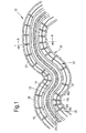
Figure 1 shows a longitudinal cross-section of part of a flexible tool according to a first embodiment of the invention; -
Figure 2 shows a transverse cross-section on the line A-A shown inFigure 1 ; -
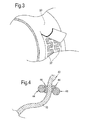
Figure 3 shows part of the outer surface of the flexible tool ofFigure 1 , with the covering layer partly removed; and -
Figure 4 shows a schematic illustration of a flexible tool according to a second embodiment of the invention. - Referring first to
Figures 1 and2 , a flexible tool according to the invention, shown generally at 10, has abackbone 12 formed of a flexible material such as a high-temperature-resistant silicone rubber. Thebackbone 12 is tubular, and defines acentral conduit 14. In use, this conduit may accommodate an optical fibre bundle, tool drive cable or the like 16. Spaced along thebackbone 12 are radially extendingprojections 18 supporting a plurality of longitudinally spacedcircular ribs 20. In this embodiment, the radially extendingprojections 18 at each axial position are equally spaced around the circumference of the backbone. It is envisaged that the diameter of the tool is less than 12mm, so that it can fit through the borescope ports of a gas turbine engine. - The bending of the tool may be controlled in a known manner, as follows. A plurality of
sheathed control wires 22 run along the length of the tool (only two are shown inFigure 1 ), and throughholes ribs 18. The wires are free to move through theholes 24 and are guided by them, in contrast to theholes 26 in which the wires are fixed in place. In the embodiment shown, joints in the tool are effectively defined by groups of four projections. The first projection fixes the control wire from the previous joint in ahole 26, while control wires for this and subsequent joints pass through ahole 24. The next two ribs support and guide the control wires throughholes 24, and the control wire for this joint is fixed in ahole 26 in the fourth rib of the group. - Considering the four projections indicated in
Figure 1 as 18a, 18b, 18c, 18d, thewire 22 is fixed inhole 26 inprojection 18d, but free to move throughholes 24 inprojections wire 22, theprojections backbone 12 to bend as shown. By suitable control of the plurality ofwires 22 any group of fourprojections 18 can be similarly controlled, and therefore (because theprojections 18 extend in different radial directions from the backbone 12) any part of the backbone can be caused to bend in a desired direction. In this way, generally under computer control, the tip of the tool can be steered through obstructions in a workspace to reach the region of interest, and the following parts of the tool can be steered as necessary to follow the tip without fouling the obstructions. - This control mechanism allows the tip of the
flexible tool 10 to be steered to any desired position within a workspace, and to avoid obstacles. In use, the tip of the flexible tool would accommodate suitable tools to perform the desired inspection or operation. Such tools may include an optical probe, a light source or a machining tip (driven by a flexible drive shaft carried through the central conduit of the flexible tool). - However, as indicated above, if known snake-arm robots are made small enough to fit through the access spaces of a gas turbine engine then their load-carrying capacity will be inadequate to perform the desired operations; load-carrying capacity is relevant both in terms of the ability to support the weight of the tools and to resist forces generated during, for example, a grinding operation. Conversely, if their load-carrying capacity is increased then they will inevitably become too large to fit through the available access spaces. The invention provides a flexible tool small enough to fit into the limited spaces in a gas turbine engine, but with sufficient load-carrying capacity to enable a wider range of operations to be performed.
- Referring again to
Figures 1 and2 , in a flexible tool according to the invention the spaces between theprojections 18 andribs 20 are filled with a cavity-fillingmedium 28. In the illustrated embodiment, themedium 28 is a thermoplastic which is rigid at the normal operating temperature of the tool. Around the outside of thetool 10, enclosing theribs 20 andmedium 28, is an outer covering orskin 30, which incorporates embedded heating elements. InFigure 3 , part of theskin 30 has been peeled back to show twoheating elements 32. - In use, the
heating elements 32 are controlled to heat the medium 28 above its glass transition temperature, so that it will melt or soften. In this first state, the medium 28 will not impede the movement of thetool 10 and so the tool may be bent (as described above) to permit the tip to be driven through a workspace to a region of interest. The medium will flow as necessary through the spaces between theprojections 18 andribs 20. A control mechanism may be provided so that, when the medium 28 is in its first state and therefore behaving effectively as a fluid, its pressure may be increased or reduced to control more precisely the stiffness of the flexible tool. In general, a higher fluid pressure will make the tool stiffer, and a lower fluid pressure will make it less stiff. This more precise control may aid the deployment of the tool within the workspace. - Once the tip of the tool is in the desired position, the heating elements are switched off so that the medium 28 will cool. Once the medium 28 cools below its glass transition temperature it will become relatively rigid, and in this second state will effectively lock the
ribs 20 andprojections 18 in their positions. The entire tool effectively becomes rigid. In this way, thetool 10 is provided with significantly greater rigidity and therefore load-carrying capacity than similar known tools. It is envisaged that, for a tool with a diameter of less than 12mm, load-carrying capacities will be achievable in the order of 0.2kg at an overhang distance of 100mm. - Once the inspection or repair operation is complete, the
heating elements 32 are again controlled to heat the medium 28 until it melts or softens back into the first state, after which thetool 10 can be withdrawn from the workspace. - In this way, a
tool 10 according to the invention can be made small and (in its first state) flexible enough to fit into confined spaces and through small access ports, such as those in gas turbine engines, but at the same time can be made (by switching into its second state) sufficiently rigid to support appreciable loads, thereby enabling a much wider range of inspection and repair operations to be performed, for example without removing a gas turbine engine from the aircraft wing. - A further advantage may be gained if separate heating elements are provided, spaced along the length of the
tool 10. If these heating elements are separately controlled, then it is possible to control the stiffness of the tool segment-by-segment, or joint-by-joint, along its length. This may facilitate the steering of the tool through difficult areas of a workspace. Alternatively, it may allow parts of the tool to be made rigid to allow operations to be performed, while keeping other parts of the tool flexible; for example, to accommodate the movement of other components. - In alternative embodiments of the invention, a different material may be used for the medium 28. For example, it may be a fibre-reinforced thermoplastic, or any other suitable material that can be made more or less stiff by heating and cooling, for example a low-melting-point alloy. It will be understood that the comments above (for example, concerning segment-by-segment control of the tool) would apply equally to such embodiments, with the necessary changes being made to the switching mechanism.
- In the embodiments described above, the stiffening and softening of the medium 28 is a repeatable process. In a further alternative embodiment, the medium is a UV-cured adhesive, and the tool is provided with optical fibres or similar light-transmitting elements to carry UV light to the medium when required. In its initial state, the adhesive is soft and so the tool is flexible; once the tool is in the desired position, UV light from a suitable source is directed into the medium to cure it, rendering it stiff and locking the tool in position. After the operations are completed, heat is applied to the adhesive (by embedded heating elements as in the first embodiment described above, or by other means) until the adhesive is degraded sufficiently to lose its stiffness. The tool can then be withdrawn from the workspace. In such an embodiment, the adhesive would not be re-usable; however, it may be possible to remove the degraded adhesive and replace it with new adhesive for the next use of the tool.
- In alternative embodiments of the invention, the control of the joints may be achieved by other means than by the control wires described above. For example, hydraulic or pneumatic actuators may be provided, or elements of shape-memory alloy may be provided in the joints which would change their shape or dimensions when subjected to an electrical impulse. It will be understood that such alternative actuators could also be individually controlled.
- In another alternative embodiment, not illustrated in the drawings, instead of a single flexible backbone 12 a segmented backbone is provided, with rotatable spherical-type joints between the segments. In this embodiment, the medium acts when stiffened to lock the joints in position, thereby providing rigidity to the tool.
-
Figure 4 illustrates a further, optional feature of a tool according to the invention, which may be combined with any of the embodiments described so far. - In
Figure 4 , atool 10 according to the invention is shown within a workspace. The tip 42 of the tool has been steered between twoobstructions 44. In a gas turbine engine, such obstructions may take the form of blades or vanes. - Two inflatable
gripping segments 46 are provided towards the tip of the tool, one on each side of the tool. The segments may be formed integrally with the skin of the tool, or may be formed separately and stitched or otherwise attached to the skin. - When the tip of the tool is in the desired position the gripping
segments 46 are inflated, as shown inFigure 4 , to support the tool between theobstructions 44. This provides a support for the tool relatively close to its tip, thereby increasing the effective stiffness of the tool. It means that the stiffness of the tool in use is not dependent on the overall length of the tool, but only on the "overhang" between the support and the tip. This enables longer flexible tools to be constructed, to reach more inaccessible workspaces, without sacrificing the rigidity of the tool or its load-carrying capacity. - When the operations have been completed, the gripping segments are deflated so that the tool can be removed.
- Other configurations of gripping segments may be used, depending on the particular requirements of the application. For example, a single annular gripping segment or a number of segments spaced around the circumference of the tool. Gripping segments may be provided in multiple positions along the length of the tool, as required.
- The gripping segments may also be used for different purposes, enhancing the capabilities of the flexible tool. For example, if the inflatable segments are inflated to secure the tool between two rotatable blades of a gas turbine engine, manual rotation of the engine could then be used to "pull" the tip of the flexible tool to a different position, further around the rotational axis of the engine. In this way, the flexible tool may provide access to regions even further inside the engine and even more remote from the access ports.
- It will be appreciated that alternative designs of gripping segments could be used, which would provide the same advantages as the inflatable segments described above. For example, one or more mechanically- or electrically-actuated gripping segments could be used, which would be folded away within the body of the tool to permit its insertion or removal, and deployed outwards from the body to provide support when required.
- The invention may also be applied in a simpler flexible tool, in which the control mechanism for the flexing of the tool is absent or is provided only along part of the length of the tool, for example in the region near to the tip. The cavity-filling medium and its associated softening/stiffening mechanism would still be present. Such a tool would be cheaper and simpler to manufacture, and would still provide the advantages of stiffness and load-carrying capacity associated with the embodiments described in more detail above.
- Elements of the invention, namely the cavity-filling medium and the gripping segments, may be applied to other designs of snake-arm robots and the like, as well as to those designs specifically described in this specification.
- The invention provides a flexible tool to facilitate access to confined or hazardous spaces, but with a greatly enhanced load-carrying capacity compared with known snake-arm robots. The additional load-carrying capacity permits operations such as grinding or deburring to be performed, which have previously been impossible because the tip of the tool has not had sufficient rigidity to react the loads involved.
Claims (13)
- A flexible tool (10), characterised in that the tool comprises stiffening means (28) switchable in use from a first state of relatively low stiffness to a second state of relatively high stiffness, and subsequently switchable from the second state back to the first state.
- A tool as claimed in claim 1, in which the stiffening means comprise thermoplastic or fibre-reinforced thermoplastic or low-melting-point alloy or ultraviolet-curable adhesive.
- A tool as claimed in claim 1 or claim 2, in which the stiffening means are repeatably switchable between the first and second states.
- A tool as claimed in any preceding claim, in which the switching is achieved by the selective application of heat (32) to the stiffening means.
- A tool as claimed in any one of claims 1 to 3, in which the switching from the first state to the second state is achieved by the selective application of ultraviolet light to the stiffening means.
- A tool as claimed in any preceding claim, in which the tool comprises a plurality of linked segments movable relative to one another, and the stiffening means act in the second state to lock the links between segments and prevent the relative movement.
- A tool as claimed in any preceding claim, and further comprising remotely operated control means to direct the flexing of the tool.
- A tool as claimed in claim 7, in which the control means comprise wires (22) or hydraulic or pneumatic actuators or shape-memory alloy elements.
- A tool as claimed in claim 7 or claim 8, and in which the tool comprises a plurality of parts or segments that can be flexed independently.
- A tool as claimed in any preceding claim, and further comprising a conduit (14) extending longitudinally through the tool.
- A tool as claimed in any preceding claim, and further comprising a gripping segment that can be actuated to locate or secure the tool in use.
- A tool as claimed in claim 12, in which the gripping segment (46) is inflatable.
- A method of performing an operation using a flexible tool as claimed in any preceding claim, the method comprising the steps of:inserting the tool into a workspace;positioning the tip of the tool at a desired position in the workspace;switching the stiffening means to the second state;performing the operation;switching the stiffening means to the first state;removing the tool from the workspace.
Applications Claiming Priority (1)
| Application Number | Priority Date | Filing Date | Title |
|---|---|---|---|
| GB201015566A GB201015566D0 (en) | 2010-09-17 | 2010-09-17 | A flexible tool |
Publications (2)
| Publication Number | Publication Date |
|---|---|
| EP2431140A1 true EP2431140A1 (en) | 2012-03-21 |
| EP2431140B1 EP2431140B1 (en) | 2015-07-29 |
Family
ID=43065383
Family Applications (1)
| Application Number | Title | Priority Date | Filing Date |
|---|---|---|---|
| EP11179839.3A Active EP2431140B1 (en) | 2010-09-17 | 2011-09-02 | A flexible tool |
Country Status (5)
| Country | Link |
|---|---|
| US (1) | US9016159B2 (en) |
| EP (1) | EP2431140B1 (en) |
| JP (1) | JP2012115979A (en) |
| ES (1) | ES2545006T3 (en) |
| GB (1) | GB201015566D0 (en) |
Cited By (9)
| Publication number | Priority date | Publication date | Assignee | Title |
|---|---|---|---|---|
| CN103358305A (en) * | 2013-06-17 | 2013-10-23 | 西安电子科技大学 | Closed-loop control available multifunctional in-water snake-shaped robot |
| CN103932794A (en) * | 2014-04-02 | 2014-07-23 | 西安交通大学 | Minimally invasive surgery operating arm structure based on DE drivers |
| CN106625575A (en) * | 2016-11-08 | 2017-05-10 | 上海宇航系统工程研究所 | Inflation type rope traction foldable and unfoldable flexible parallel mechanism |
| CN107139199A (en) * | 2017-05-17 | 2017-09-08 | 浙江工业大学 | A kind of small flexible aspirated-air type gripper equipment |
| US10213919B2 (en) | 2015-03-23 | 2019-02-26 | Rolls-Royce Plc | Flexible tools and apparatus for machining objects |
| EP3459696A1 (en) * | 2017-08-18 | 2019-03-27 | Rolls-Royce plc | Hyper-redundant manipulators |
| WO2019175069A1 (en) * | 2018-03-14 | 2019-09-19 | Daimler Ag | Feed apparatus for a manipulator arm having at least one joint, and stiffening device for such a feed apparatus |
| WO2020156910A1 (en) * | 2019-01-31 | 2020-08-06 | Daimler Ag | Guiding device for guiding at least one line and/or at least one medium, and use of such a guiding device |
| CN115958615A (en) * | 2023-01-09 | 2023-04-14 | 江西理工大学 | Variable-rigidity temperature control method and structure of low-melting-point alloy and soft manipulator |
Families Citing this family (36)
| Publication number | Priority date | Publication date | Assignee | Title |
|---|---|---|---|---|
| US9687303B2 (en) | 2012-04-20 | 2017-06-27 | Vanderbilt University | Dexterous wrists for surgical intervention |
| US9713873B2 (en) * | 2012-05-12 | 2017-07-25 | Massachusetts Institute Of Technology | Continuum style manipulator actuated with phase change media |
| US20150190613A1 (en) * | 2012-07-20 | 2015-07-09 | Steadfast Surgical, Inc. | Manually positioned armature system and method of use |
| US11793394B2 (en) | 2016-12-02 | 2023-10-24 | Vanderbilt University | Steerable endoscope with continuum manipulator |
| GB2557269B (en) | 2016-12-02 | 2020-05-06 | Rolls Royce Plc | Hyper redundant robots |
| JP6647235B2 (en) * | 2017-02-28 | 2020-02-14 | キヤノン株式会社 | Wire-driven manipulator |
| GB2560354A (en) * | 2017-03-09 | 2018-09-12 | Rolls Royce Plc | Continuum robots |
| WO2019055701A1 (en) * | 2017-09-13 | 2019-03-21 | Vanderbilt University | Continuum robots with multi-scale motion through equilibrium modulation |
| FR3073440B1 (en) * | 2017-11-16 | 2019-10-25 | Warein | INFLATABLE TUBE WITH VARIABLE GEOMETRY AND CONSTANT VOLUME, ROBOTIC ARM AND ROBOT |
| US20190337102A1 (en) * | 2018-05-07 | 2019-11-07 | General Electric Company | Interlocking Stage of Airfoils |
| US10962345B2 (en) | 2018-05-23 | 2021-03-30 | General Electric Company | Tool and method for inspecting an annular space of an engine |
| US11707819B2 (en) | 2018-10-15 | 2023-07-25 | General Electric Company | Selectively flexible extension tool |
| US12194620B2 (en) | 2018-10-15 | 2025-01-14 | Oliver Crisipin Robotics Limited | Selectively flexible extension tool |
| GB201820507D0 (en) * | 2018-12-17 | 2019-01-30 | Rolls Royce Plc | Positioning device |
| US11702955B2 (en) | 2019-01-14 | 2023-07-18 | General Electric Company | Component repair system and method |
| US12405187B2 (en) | 2019-10-04 | 2025-09-02 | General Electric Company | Insertion apparatus for use with rotary machines |
| US11530621B2 (en) * | 2019-10-16 | 2022-12-20 | General Electric Company | Systems and method for use in servicing a machine |
| US10884232B1 (en) * | 2019-12-30 | 2021-01-05 | General Electric Company | Insertion apparatus including rigidizable body |
| US11692650B2 (en) | 2020-01-23 | 2023-07-04 | General Electric Company | Selectively flexible extension tool |
| US11752622B2 (en) | 2020-01-23 | 2023-09-12 | General Electric Company | Extension tool having a plurality of links |
| US11613003B2 (en) | 2020-01-24 | 2023-03-28 | General Electric Company | Line assembly for an extension tool having a plurality of links |
| US11371437B2 (en) | 2020-03-10 | 2022-06-28 | Oliver Crispin Robotics Limited | Insertion tool |
| US12091981B2 (en) | 2020-06-11 | 2024-09-17 | General Electric Company | Insertion tool and method |
| KR102362098B1 (en) * | 2020-07-27 | 2022-02-11 | 한국로봇융합연구원 | Robot Gripper with Stopper Device using Low Melting Point Alloy and Control Method thereof |
| CN112536789B (en) * | 2020-12-02 | 2022-04-12 | 山东大学 | Rigid-flexible combined type outer limb mechanical arm and auxiliary operation device thereof |
| US11977217B2 (en) | 2020-12-04 | 2024-05-07 | General Electric Company | Insertion tool |
| US12416800B2 (en) | 2021-01-08 | 2025-09-16 | General Electric Company | Insertion tool |
| US12504616B2 (en) | 2021-01-08 | 2025-12-23 | General Electric Company | Insertion tool |
| JP7546912B2 (en) * | 2021-02-12 | 2024-09-09 | 国立大学法人東北大学 | Variable stiffness deformation body and variable stiffness mechanism |
| US11913344B2 (en) | 2021-02-25 | 2024-02-27 | General Electric Company | Multi-tube servicing tool and method of servicing gas turbine engine components |
| US11654547B2 (en) | 2021-03-31 | 2023-05-23 | General Electric Company | Extension tool |
| CN113635316A (en) * | 2021-07-30 | 2021-11-12 | 西安交通大学 | Multi-form and multifunctional blanket type robot under vibration excitation |
| US11787069B2 (en) | 2021-11-01 | 2023-10-17 | Oliver Crispin Robotics Limited | Insertion tool with flexible spine |
| EP4201603A1 (en) * | 2021-12-21 | 2023-06-28 | Rolls-Royce plc | Means for stiffening a continuum arm robot |
| US12186848B1 (en) | 2024-01-26 | 2025-01-07 | General Electric Company | Method and apparatus for servicing engines |
| US12195202B1 (en) * | 2024-01-26 | 2025-01-14 | General Electric Company | System and method for servicing aircraft engines |
Citations (5)
| Publication number | Priority date | Publication date | Assignee | Title |
|---|---|---|---|---|
| US4784042A (en) * | 1986-02-12 | 1988-11-15 | Nathaniel A. Hardin | Method and system employing strings of opposed gaseous-fluid inflatable tension actuators in jointed arms, legs, beams and columns for controlling their movements |
| US20050099254A1 (en) * | 2003-11-12 | 2005-05-12 | Ohnstein Thomas R. | Robotic member |
| WO2006060775A2 (en) * | 2004-12-02 | 2006-06-08 | Sarcos Investments Lc | Mechanical serpentine device |
| US20080205980A1 (en) * | 2007-02-27 | 2008-08-28 | Carnegie Mellon University | System for releasably attaching a disposable device to a durable device |
| US20080302200A1 (en) * | 2007-06-06 | 2008-12-11 | Tobey Wayland E | Modular hybrid snake arm |
Family Cites Families (10)
| Publication number | Priority date | Publication date | Assignee | Title |
|---|---|---|---|---|
| WO1998049944A1 (en) * | 1997-05-02 | 1998-11-12 | Pilling Weck Incorporated | Adjustable supporting bracket having plural ball and socket joints |
| EP1662972A4 (en) * | 2000-04-03 | 2010-08-25 | Intuitive Surgical Inc | Activated polymer articulated instruments and methods of insertion |
| US7678117B2 (en) * | 2004-06-07 | 2010-03-16 | Novare Surgical Systems, Inc. | Articulating mechanism with flex-hinged links |
| EP1799771A2 (en) * | 2004-10-06 | 2007-06-27 | Cornerstone Research Group, Inc. | Light activated shape memory co-polymers |
| US8376960B2 (en) | 2005-07-27 | 2013-02-19 | Boston Scientific Scimed, Inc. | Medical devices with variable stiffness |
| BRPI0712590A2 (en) | 2006-05-22 | 2012-07-03 | Koninkl Philips Electronics Nv | sheath for guiding materials into a body cavity, method for navigating it, and navigable sheath and catheter assembly. |
| WO2007134461A1 (en) * | 2006-05-24 | 2007-11-29 | Titan Medical Inc. | Snaking robotic arm with movable shapers |
| US7789827B2 (en) * | 2006-08-21 | 2010-09-07 | Karl Storz Endovision, Inc. | Variable shaft flexibility in endoscope |
| JP2009056558A (en) * | 2007-08-31 | 2009-03-19 | Toshiba Corp | manipulator |
| KR101060622B1 (en) | 2008-10-22 | 2011-08-31 | 한국과학기술원 | Multi-joint device using rheology fluid |
-
2010
- 2010-09-17 GB GB201015566A patent/GB201015566D0/en not_active Ceased
-
2011
- 2011-09-02 ES ES11179839.3T patent/ES2545006T3/en active Active
- 2011-09-02 US US13/224,783 patent/US9016159B2/en active Active
- 2011-09-02 EP EP11179839.3A patent/EP2431140B1/en active Active
- 2011-09-16 JP JP2011203100A patent/JP2012115979A/en not_active Withdrawn
Patent Citations (5)
| Publication number | Priority date | Publication date | Assignee | Title |
|---|---|---|---|---|
| US4784042A (en) * | 1986-02-12 | 1988-11-15 | Nathaniel A. Hardin | Method and system employing strings of opposed gaseous-fluid inflatable tension actuators in jointed arms, legs, beams and columns for controlling their movements |
| US20050099254A1 (en) * | 2003-11-12 | 2005-05-12 | Ohnstein Thomas R. | Robotic member |
| WO2006060775A2 (en) * | 2004-12-02 | 2006-06-08 | Sarcos Investments Lc | Mechanical serpentine device |
| US20080205980A1 (en) * | 2007-02-27 | 2008-08-28 | Carnegie Mellon University | System for releasably attaching a disposable device to a durable device |
| US20080302200A1 (en) * | 2007-06-06 | 2008-12-11 | Tobey Wayland E | Modular hybrid snake arm |
Cited By (18)
| Publication number | Priority date | Publication date | Assignee | Title |
|---|---|---|---|---|
| CN103358305A (en) * | 2013-06-17 | 2013-10-23 | 西安电子科技大学 | Closed-loop control available multifunctional in-water snake-shaped robot |
| CN103358305B (en) * | 2013-06-17 | 2015-05-20 | 西安电子科技大学 | Closed-loop control available multifunctional in-water snake-shaped robot |
| CN103932794A (en) * | 2014-04-02 | 2014-07-23 | 西安交通大学 | Minimally invasive surgery operating arm structure based on DE drivers |
| CN103932794B (en) * | 2014-04-02 | 2015-12-09 | 西安交通大学 | A kind of Minimally Invasive Surgery motion arm structure based on DE driver |
| US10213919B2 (en) | 2015-03-23 | 2019-02-26 | Rolls-Royce Plc | Flexible tools and apparatus for machining objects |
| CN106625575A (en) * | 2016-11-08 | 2017-05-10 | 上海宇航系统工程研究所 | Inflation type rope traction foldable and unfoldable flexible parallel mechanism |
| CN106625575B (en) * | 2016-11-08 | 2019-02-01 | 上海宇航系统工程研究所 | A kind of inflatable wire saws can take down the exhibits flexible parallel mechanism |
| CN107139199A (en) * | 2017-05-17 | 2017-09-08 | 浙江工业大学 | A kind of small flexible aspirated-air type gripper equipment |
| EP3459696A1 (en) * | 2017-08-18 | 2019-03-27 | Rolls-Royce plc | Hyper-redundant manipulators |
| WO2019175069A1 (en) * | 2018-03-14 | 2019-09-19 | Daimler Ag | Feed apparatus for a manipulator arm having at least one joint, and stiffening device for such a feed apparatus |
| CN111867786A (en) * | 2018-03-14 | 2020-10-30 | 戴姆勒股份公司 | Supply device for an operating robotic arm having at least one joint and hardening mechanism for such a supply device |
| US11697212B2 (en) | 2018-03-14 | 2023-07-11 | Daimler Ag | Feeding device for a manipulator arm having at least one joint and stiffening device for such a feeding device |
| CN111867786B (en) * | 2018-03-14 | 2024-03-15 | 梅赛德斯-奔驰集团股份公司 | Supply device for an operating arm with at least one joint and hardening mechanism for such a supply device |
| WO2020156910A1 (en) * | 2019-01-31 | 2020-08-06 | Daimler Ag | Guiding device for guiding at least one line and/or at least one medium, and use of such a guiding device |
| CN113396516A (en) * | 2019-01-31 | 2021-09-14 | 戴姆勒股份公司 | Guiding device for guiding at least one line and/or at least one medium and use of such a guiding device |
| CN113396516B (en) * | 2019-01-31 | 2023-08-08 | 梅赛德斯-奔驰集团股份公司 | Guiding device for guiding at least one pipeline and/or at least one medium and use of such a guiding device |
| US11831135B2 (en) | 2019-01-31 | 2023-11-28 | Daimler Ag | Guide device for guiding at least one conduit and/or at least one medium and use of such a guide device |
| CN115958615A (en) * | 2023-01-09 | 2023-04-14 | 江西理工大学 | Variable-rigidity temperature control method and structure of low-melting-point alloy and soft manipulator |
Also Published As
| Publication number | Publication date |
|---|---|
| GB201015566D0 (en) | 2010-10-27 |
| US20120067158A1 (en) | 2012-03-22 |
| JP2012115979A (en) | 2012-06-21 |
| ES2545006T3 (en) | 2015-09-07 |
| US9016159B2 (en) | 2015-04-28 |
| EP2431140B1 (en) | 2015-07-29 |
Similar Documents
| Publication | Publication Date | Title |
|---|---|---|
| EP2431140B1 (en) | A flexible tool | |
| US20240326266A1 (en) | Selectively flexible extension tool | |
| CA3058055C (en) | Selectively flexible extension tool | |
| US9649163B2 (en) | Introduction devices for highly articulated robotic probes and methods of production and use of such probes | |
| CN103517790B (en) | Multi-joint industrial manipulator | |
| EP2165808B1 (en) | An industrial robot | |
| US20200346310A1 (en) | Repair tool for turbomachinery and related method | |
| JP7225206B2 (en) | Systems and methods for maintaining machines | |
| BRPI1014290B1 (en) | non-destructive in situ control device for parts of an engine, in particular turbomachinery | |
| EP4091774A1 (en) | A mechanism | |
| US12186848B1 (en) | Method and apparatus for servicing engines | |
| US12251832B2 (en) | Robot stiffness | |
| US11517187B2 (en) | System and method for endoscope locomotion and shaping | |
| US20140352483A1 (en) | Remote alignment tool | |
| US20200191172A1 (en) | Positioning device | |
| JP6856189B2 (en) | Excavator, excavator using excavator | |
| ES2967062T3 (en) | robotic device | |
| JP2012081528A (en) | Articulated robot | |
| JP6815620B2 (en) | Cylindrical body and excavator | |
| CN118928814A (en) | Ultra-long flexible robotic arm in space | |
| CN112808711A (en) | Pipeline dredging device and system |
Legal Events
| Date | Code | Title | Description |
|---|---|---|---|
| PUAI | Public reference made under article 153(3) epc to a published international application that has entered the european phase |
Free format text: ORIGINAL CODE: 0009012 |
|
| 17P | Request for examination filed |
Effective date: 20120203 |
|
| AK | Designated contracting states |
Kind code of ref document: A1 Designated state(s): AL AT BE BG CH CY CZ DE DK EE ES FI FR GB GR HR HU IE IS IT LI LT LU LV MC MK MT NL NO PL PT RO RS SE SI SK SM TR |
|
| AX | Request for extension of the european patent |
Extension state: BA ME |
|
| 17Q | First examination report despatched |
Effective date: 20140611 |
|
| GRAP | Despatch of communication of intention to grant a patent |
Free format text: ORIGINAL CODE: EPIDOSNIGR1 |
|
| INTG | Intention to grant announced |
Effective date: 20150508 |
|
| GRAS | Grant fee paid |
Free format text: ORIGINAL CODE: EPIDOSNIGR3 |
|
| GRAA | (expected) grant |
Free format text: ORIGINAL CODE: 0009210 |
|
| AK | Designated contracting states |
Kind code of ref document: B1 Designated state(s): AL AT BE BG CH CY CZ DE DK EE ES FI FR GB GR HR HU IE IS IT LI LT LU LV MC MK MT NL NO PL PT RO RS SE SI SK SM TR |
|
| RAP1 | Party data changed (applicant data changed or rights of an application transferred) |
Owner name: ROLLS-ROYCE PLC |
|
| REG | Reference to a national code |
Ref country code: GB Ref legal event code: FG4D |
|
| REG | Reference to a national code |
Ref country code: CH Ref legal event code: EP |
|
| REG | Reference to a national code |
Ref country code: NL Ref legal event code: T3 |
|
| REG | Reference to a national code |
Ref country code: AT Ref legal event code: REF Ref document number: 738896 Country of ref document: AT Kind code of ref document: T Effective date: 20150815 |
|
| REG | Reference to a national code |
Ref country code: IE Ref legal event code: FG4D |
|
| REG | Reference to a national code |
Ref country code: ES Ref legal event code: FG2A Ref document number: 2545006 Country of ref document: ES Kind code of ref document: T3 Effective date: 20150907 |
|
| REG | Reference to a national code |
Ref country code: DE Ref legal event code: R096 Ref document number: 602011018171 Country of ref document: DE |
|
| REG | Reference to a national code |
Ref country code: AT Ref legal event code: MK05 Ref document number: 738896 Country of ref document: AT Kind code of ref document: T Effective date: 20150729 |
|
| REG | Reference to a national code |
Ref country code: LT Ref legal event code: MG4D |
|
| PG25 | Lapsed in a contracting state [announced via postgrant information from national office to epo] |
Ref country code: LT Free format text: LAPSE BECAUSE OF FAILURE TO SUBMIT A TRANSLATION OF THE DESCRIPTION OR TO PAY THE FEE WITHIN THE PRESCRIBED TIME-LIMIT Effective date: 20150729 Ref country code: LV Free format text: LAPSE BECAUSE OF FAILURE TO SUBMIT A TRANSLATION OF THE DESCRIPTION OR TO PAY THE FEE WITHIN THE PRESCRIBED TIME-LIMIT Effective date: 20150729 Ref country code: GR Free format text: LAPSE BECAUSE OF FAILURE TO SUBMIT A TRANSLATION OF THE DESCRIPTION OR TO PAY THE FEE WITHIN THE PRESCRIBED TIME-LIMIT Effective date: 20151030 Ref country code: NO Free format text: LAPSE BECAUSE OF FAILURE TO SUBMIT A TRANSLATION OF THE DESCRIPTION OR TO PAY THE FEE WITHIN THE PRESCRIBED TIME-LIMIT Effective date: 20151029 Ref country code: FI Free format text: LAPSE BECAUSE OF FAILURE TO SUBMIT A TRANSLATION OF THE DESCRIPTION OR TO PAY THE FEE WITHIN THE PRESCRIBED TIME-LIMIT Effective date: 20150729 |
|
| PG25 | Lapsed in a contracting state [announced via postgrant information from national office to epo] |
Ref country code: PT Free format text: LAPSE BECAUSE OF FAILURE TO SUBMIT A TRANSLATION OF THE DESCRIPTION OR TO PAY THE FEE WITHIN THE PRESCRIBED TIME-LIMIT Effective date: 20151130 Ref country code: AT Free format text: LAPSE BECAUSE OF FAILURE TO SUBMIT A TRANSLATION OF THE DESCRIPTION OR TO PAY THE FEE WITHIN THE PRESCRIBED TIME-LIMIT Effective date: 20150729 Ref country code: PL Free format text: LAPSE BECAUSE OF FAILURE TO SUBMIT A TRANSLATION OF THE DESCRIPTION OR TO PAY THE FEE WITHIN THE PRESCRIBED TIME-LIMIT Effective date: 20150729 Ref country code: HR Free format text: LAPSE BECAUSE OF FAILURE TO SUBMIT A TRANSLATION OF THE DESCRIPTION OR TO PAY THE FEE WITHIN THE PRESCRIBED TIME-LIMIT Effective date: 20150729 Ref country code: RS Free format text: LAPSE BECAUSE OF FAILURE TO SUBMIT A TRANSLATION OF THE DESCRIPTION OR TO PAY THE FEE WITHIN THE PRESCRIBED TIME-LIMIT Effective date: 20150729 Ref country code: IS Free format text: LAPSE BECAUSE OF FAILURE TO SUBMIT A TRANSLATION OF THE DESCRIPTION OR TO PAY THE FEE WITHIN THE PRESCRIBED TIME-LIMIT Effective date: 20151129 Ref country code: SE Free format text: LAPSE BECAUSE OF FAILURE TO SUBMIT A TRANSLATION OF THE DESCRIPTION OR TO PAY THE FEE WITHIN THE PRESCRIBED TIME-LIMIT Effective date: 20150729 |
|
| PG25 | Lapsed in a contracting state [announced via postgrant information from national office to epo] |
Ref country code: DK Free format text: LAPSE BECAUSE OF FAILURE TO SUBMIT A TRANSLATION OF THE DESCRIPTION OR TO PAY THE FEE WITHIN THE PRESCRIBED TIME-LIMIT Effective date: 20150729 Ref country code: MC Free format text: LAPSE BECAUSE OF FAILURE TO SUBMIT A TRANSLATION OF THE DESCRIPTION OR TO PAY THE FEE WITHIN THE PRESCRIBED TIME-LIMIT Effective date: 20150729 Ref country code: SK Free format text: LAPSE BECAUSE OF FAILURE TO SUBMIT A TRANSLATION OF THE DESCRIPTION OR TO PAY THE FEE WITHIN THE PRESCRIBED TIME-LIMIT Effective date: 20150729 Ref country code: IT Free format text: LAPSE BECAUSE OF FAILURE TO SUBMIT A TRANSLATION OF THE DESCRIPTION OR TO PAY THE FEE WITHIN THE PRESCRIBED TIME-LIMIT Effective date: 20150729 Ref country code: EE Free format text: LAPSE BECAUSE OF FAILURE TO SUBMIT A TRANSLATION OF THE DESCRIPTION OR TO PAY THE FEE WITHIN THE PRESCRIBED TIME-LIMIT Effective date: 20150729 Ref country code: LU Free format text: LAPSE BECAUSE OF FAILURE TO SUBMIT A TRANSLATION OF THE DESCRIPTION OR TO PAY THE FEE WITHIN THE PRESCRIBED TIME-LIMIT Effective date: 20150902 Ref country code: CZ Free format text: LAPSE BECAUSE OF FAILURE TO SUBMIT A TRANSLATION OF THE DESCRIPTION OR TO PAY THE FEE WITHIN THE PRESCRIBED TIME-LIMIT Effective date: 20150729 |
|
| REG | Reference to a national code |
Ref country code: CH Ref legal event code: PL |
|
| REG | Reference to a national code |
Ref country code: DE Ref legal event code: R097 Ref document number: 602011018171 Country of ref document: DE |
|
| REG | Reference to a national code |
Ref country code: DE Ref legal event code: R082 Ref document number: 602011018171 Country of ref document: DE Representative=s name: HERNANDEZ, YORCK, DIPL.-ING., DE |
|
| PG25 | Lapsed in a contracting state [announced via postgrant information from national office to epo] |
Ref country code: RO Free format text: LAPSE BECAUSE OF FAILURE TO SUBMIT A TRANSLATION OF THE DESCRIPTION OR TO PAY THE FEE WITHIN THE PRESCRIBED TIME-LIMIT Effective date: 20150729 |
|
| PLBE | No opposition filed within time limit |
Free format text: ORIGINAL CODE: 0009261 |
|
| STAA | Information on the status of an ep patent application or granted ep patent |
Free format text: STATUS: NO OPPOSITION FILED WITHIN TIME LIMIT |
|
| REG | Reference to a national code |
Ref country code: IE Ref legal event code: MM4A |
|
| 26N | No opposition filed |
Effective date: 20160502 |
|
| PG25 | Lapsed in a contracting state [announced via postgrant information from national office to epo] |
Ref country code: LI Free format text: LAPSE BECAUSE OF NON-PAYMENT OF DUE FEES Effective date: 20150930 Ref country code: IE Free format text: LAPSE BECAUSE OF NON-PAYMENT OF DUE FEES Effective date: 20150902 Ref country code: CH Free format text: LAPSE BECAUSE OF NON-PAYMENT OF DUE FEES Effective date: 20150930 |
|
| PG25 | Lapsed in a contracting state [announced via postgrant information from national office to epo] |
Ref country code: SI Free format text: LAPSE BECAUSE OF FAILURE TO SUBMIT A TRANSLATION OF THE DESCRIPTION OR TO PAY THE FEE WITHIN THE PRESCRIBED TIME-LIMIT Effective date: 20150729 |
|
| REG | Reference to a national code |
Ref country code: FR Ref legal event code: PLFP Year of fee payment: 6 |
|
| PG25 | Lapsed in a contracting state [announced via postgrant information from national office to epo] |
Ref country code: BE Free format text: LAPSE BECAUSE OF FAILURE TO SUBMIT A TRANSLATION OF THE DESCRIPTION OR TO PAY THE FEE WITHIN THE PRESCRIBED TIME-LIMIT Effective date: 20150729 |
|
| PG25 | Lapsed in a contracting state [announced via postgrant information from national office to epo] |
Ref country code: MT Free format text: LAPSE BECAUSE OF FAILURE TO SUBMIT A TRANSLATION OF THE DESCRIPTION OR TO PAY THE FEE WITHIN THE PRESCRIBED TIME-LIMIT Effective date: 20150729 |
|
| PG25 | Lapsed in a contracting state [announced via postgrant information from national office to epo] |
Ref country code: BG Free format text: LAPSE BECAUSE OF FAILURE TO SUBMIT A TRANSLATION OF THE DESCRIPTION OR TO PAY THE FEE WITHIN THE PRESCRIBED TIME-LIMIT Effective date: 20150729 Ref country code: SM Free format text: LAPSE BECAUSE OF FAILURE TO SUBMIT A TRANSLATION OF THE DESCRIPTION OR TO PAY THE FEE WITHIN THE PRESCRIBED TIME-LIMIT Effective date: 20150729 Ref country code: HU Free format text: LAPSE BECAUSE OF FAILURE TO SUBMIT A TRANSLATION OF THE DESCRIPTION OR TO PAY THE FEE WITHIN THE PRESCRIBED TIME-LIMIT; INVALID AB INITIO Effective date: 20110902 |
|
| PG25 | Lapsed in a contracting state [announced via postgrant information from national office to epo] |
Ref country code: CY Free format text: LAPSE BECAUSE OF FAILURE TO SUBMIT A TRANSLATION OF THE DESCRIPTION OR TO PAY THE FEE WITHIN THE PRESCRIBED TIME-LIMIT Effective date: 20150729 |
|
| PG25 | Lapsed in a contracting state [announced via postgrant information from national office to epo] |
Ref country code: TR Free format text: LAPSE BECAUSE OF FAILURE TO SUBMIT A TRANSLATION OF THE DESCRIPTION OR TO PAY THE FEE WITHIN THE PRESCRIBED TIME-LIMIT Effective date: 20150729 |
|
| REG | Reference to a national code |
Ref country code: FR Ref legal event code: PLFP Year of fee payment: 7 |
|
| PG25 | Lapsed in a contracting state [announced via postgrant information from national office to epo] |
Ref country code: MK Free format text: LAPSE BECAUSE OF FAILURE TO SUBMIT A TRANSLATION OF THE DESCRIPTION OR TO PAY THE FEE WITHIN THE PRESCRIBED TIME-LIMIT Effective date: 20150729 |
|
| REG | Reference to a national code |
Ref country code: FR Ref legal event code: PLFP Year of fee payment: 8 |
|
| PG25 | Lapsed in a contracting state [announced via postgrant information from national office to epo] |
Ref country code: AL Free format text: LAPSE BECAUSE OF FAILURE TO SUBMIT A TRANSLATION OF THE DESCRIPTION OR TO PAY THE FEE WITHIN THE PRESCRIBED TIME-LIMIT Effective date: 20150729 |
|
| P01 | Opt-out of the competence of the unified patent court (upc) registered |
Effective date: 20230528 |
|
| PGFP | Annual fee paid to national office [announced via postgrant information from national office to epo] |
Ref country code: NL Payment date: 20230926 Year of fee payment: 13 |
|
| PGFP | Annual fee paid to national office [announced via postgrant information from national office to epo] |
Ref country code: ES Payment date: 20231017 Year of fee payment: 13 |
|
| PGFP | Annual fee paid to national office [announced via postgrant information from national office to epo] |
Ref country code: DE Payment date: 20240926 Year of fee payment: 14 |
|
| PGFP | Annual fee paid to national office [announced via postgrant information from national office to epo] |
Ref country code: FR Payment date: 20240925 Year of fee payment: 14 |
|
| REG | Reference to a national code |
Ref country code: NL Ref legal event code: MM Effective date: 20241001 |
|
| PG25 | Lapsed in a contracting state [announced via postgrant information from national office to epo] |
Ref country code: NL Free format text: LAPSE BECAUSE OF NON-PAYMENT OF DUE FEES Effective date: 20241001 |
|
| PGFP | Annual fee paid to national office [announced via postgrant information from national office to epo] |
Ref country code: GB Payment date: 20250923 Year of fee payment: 15 |
|
| REG | Reference to a national code |
Ref country code: ES Ref legal event code: FD2A Effective date: 20251024 |
|
| PG25 | Lapsed in a contracting state [announced via postgrant information from national office to epo] |
Ref country code: ES Free format text: LAPSE BECAUSE OF NON-PAYMENT OF DUE FEES Effective date: 20240903 |