EP2431096A1 - Cyclone separator - Google Patents
Cyclone separator Download PDFInfo
- Publication number
- EP2431096A1 EP2431096A1 EP10177470A EP10177470A EP2431096A1 EP 2431096 A1 EP2431096 A1 EP 2431096A1 EP 10177470 A EP10177470 A EP 10177470A EP 10177470 A EP10177470 A EP 10177470A EP 2431096 A1 EP2431096 A1 EP 2431096A1
- Authority
- EP
- European Patent Office
- Prior art keywords
- cyclone separator
- body portion
- gas outlet
- outlet tube
- face
- Prior art date
- Legal status (The legal status is an assumption and is not a legal conclusion. Google has not performed a legal analysis and makes no representation as to the accuracy of the status listed.)
- Granted
Links
Images
Classifications
-
- B—PERFORMING OPERATIONS; TRANSPORTING
- B01—PHYSICAL OR CHEMICAL PROCESSES OR APPARATUS IN GENERAL
- B01D—SEPARATION
- B01D45/00—Separating dispersed particles from gases or vapours by gravity, inertia, or centrifugal forces
- B01D45/12—Separating dispersed particles from gases or vapours by gravity, inertia, or centrifugal forces by centrifugal forces
- B01D45/16—Separating dispersed particles from gases or vapours by gravity, inertia, or centrifugal forces by centrifugal forces generated by the winding course of the gas stream, the centrifugal forces being generated solely or partly by mechanical means, e.g. fixed swirl vanes
-
- B—PERFORMING OPERATIONS; TRANSPORTING
- B01—PHYSICAL OR CHEMICAL PROCESSES OR APPARATUS IN GENERAL
- B01D—SEPARATION
- B01D45/00—Separating dispersed particles from gases or vapours by gravity, inertia, or centrifugal forces
- B01D45/12—Separating dispersed particles from gases or vapours by gravity, inertia, or centrifugal forces by centrifugal forces
-
- B—PERFORMING OPERATIONS; TRANSPORTING
- B04—CENTRIFUGAL APPARATUS OR MACHINES FOR CARRYING-OUT PHYSICAL OR CHEMICAL PROCESSES
- B04C—APPARATUS USING FREE VORTEX FLOW, e.g. CYCLONES
- B04C5/00—Apparatus in which the axial direction of the vortex is reversed
- B04C5/02—Construction of inlets by which the vortex flow is generated, e.g. tangential admission, the fluid flow being forced to follow a downward path by spirally wound bulkheads, or with slightly downwardly-directed tangential admission
- B04C5/04—Tangential inlets
-
- B—PERFORMING OPERATIONS; TRANSPORTING
- B04—CENTRIFUGAL APPARATUS OR MACHINES FOR CARRYING-OUT PHYSICAL OR CHEMICAL PROCESSES
- B04C—APPARATUS USING FREE VORTEX FLOW, e.g. CYCLONES
- B04C5/00—Apparatus in which the axial direction of the vortex is reversed
- B04C5/08—Vortex chamber constructions
- B04C5/081—Shapes or dimensions
-
- B—PERFORMING OPERATIONS; TRANSPORTING
- B04—CENTRIFUGAL APPARATUS OR MACHINES FOR CARRYING-OUT PHYSICAL OR CHEMICAL PROCESSES
- B04C—APPARATUS USING FREE VORTEX FLOW, e.g. CYCLONES
- B04C5/00—Apparatus in which the axial direction of the vortex is reversed
- B04C5/12—Construction of the overflow ducting, e.g. diffusing or spiral exits
- B04C5/13—Construction of the overflow ducting, e.g. diffusing or spiral exits formed as a vortex finder and extending into the vortex chamber; Discharge from vortex finder otherwise than at the top of the cyclone; Devices for controlling the overflow
Definitions
- the invention is related to a cyclone separator, and is more particularly directed to a cyclone separator for circulating fluidized bed (CFB) boilers.
- CFB fluidized bed
- the circulating fluidized bed boilers require the capture of the particles that are entrained out of a reactor by reactor gases and their separation from the gases in order to recirculate it into said reactor for complete reaction.
- Cyclonic separation is a method of removing particulates from gases, without the use of filters, through vortex separation. Rotational effects and gravity are used to separate mixtures of solids and gases.
- Document US 5,771,844 discloses a cyclone separator able to operate at a body mean axial velocity of 8 m/s with a capture efficiency which is similar to the efficiency of the cyclone separators that are efficient for an axial mean velocity of 6 m/s.
- This cyclone separator suffers the shortcoming that it makes the inlet duct more costly due to the stiffening needs of the unusually wide vertical dimension.
- the cyclone barrel is higher in order to locate the high vertical dimension of the opening.
- the cyclone separator body is more expensive than for lower ratios.
- the total height of such a cyclone impacts detrimentally the arrangement of the whole system.
- An object of the present invention is to provide a cyclone separator in such a manner to solve the above described problems.
- a cyclone separator for particle collection from a gas stream containing entrained solid particles, said cyclone separator comprising:
- the ratio (d/D) of the distance (d) between the parallel to the extrados face dropped from the tip of the cyclone separator and the closest point of the gas outlet tube to the internal diameter (D) of the body portion is preferably comprised between 0.1 and 0.2, more preferably between 0.1 and 0.15 and even more preferably between 0.12 and 0.15.
- the ratio (h/w) of the height (h) of the inlet duct to the width (w) of the inlet duct at the tip of the cyclone separator is preferably comprised between 3 and 4, and more preferably between 3.5 and 4.
- Table 1 d/D s/S h/w ⁇ 0.1 0.24-0.32 ⁇ 4 ⁇ 0.1 0.26-0.30 or 0.27-0.29 ⁇ 4 0.1-0.2 0.24-0.32 ⁇ 4 0.1-0.2 0.26-0.30 or 0.27-0.29 ⁇ 4 0.1-0.15 0.24-0.32 ⁇ 4 0.1-0.15 0.26-0.30 or 0.27-0.29 ⁇ 4 0.12-0.15 0.24-0.32 ⁇ 4 0.12-0.15 0.26-0.30 or 0.27-0.29 ⁇ 4 0.12-0.15 0.24-0.32 ⁇ 4 0.12-0.15 0.26-0.30 or 0.27-0.29 ⁇ 4 ⁇ 0.1 0.24-0.32 3-4 ⁇ 0.1 0.26-0.30 or 0.27-0.29 3-4 0.1-0.2 0.24-0.32 3-4 0.1-0.26-0.30 or 0.27-0.29 3-4 0.1-0.15 0.24-0.32 3-4 0.1-0.15 0.26-0.30 or 0.27-0.29 3-4 0.12-0.15 0.26-0
- the cyclone according to the invention avoids most of the direct leak of small particles from the cyclone entrance to the cyclone exit in the gas outlet tube, thus providing a good cyclone capture efficiency of small particles even for high mean gas axial velocity such as 8m/s and higher and allowing a reduction of the diameter of the body portion.
- the distance between the projection of the body portion centre on a perpendicular to the extrados face and the projection of the gas outlet tube lower extremity centre on a perpendicular to the extrados face can be comprised between 0.04D and 0.08D, D being the internal diameter of the body portion.
- the ratio (a/S) of the cross-sectional area (a) of the gas outlet tube lower extremity to the cross-sectional area (S) of the body portion can be comprised between 0.13 and 0.20, and more preferably between 0.15 and 0.20.
- the height of the inlet duct does not exceed the internal diameter (D) of the body portion.
- the height of the body portion can be less than 1.2D, D being the internal diameter of the body portion.
- the gas outlet tube can comprise a lower conical portion and an upper cylindrical portion.
- the inlet orifice of the gas outlet tube can have a lower section than the section of the upper cylindrical portion of the gas outlet tube.
- the diameter (D v ) of the cylindrical portion and the diameter (d v ) at the lower part of the conical portion can be such that 0 ⁇ D v - d v ⁇ 0.3L, L being the height of the conical portion of the gas outlet tube.
- the intrados face ending at the tip of the cyclone separator said intrados face which connects the starting point of the inlet duct to the point at the tip of the cyclone separator can have a profile such that it comprises at least two distinct tangents so that one intersects the extrados face at a point located upstream of the foot of the perpendicular to the extrados face taken from the tip of the cyclone separator, and said intrados face can start from said point by a first part having a rectilinear profile, followed by a second part having a curved profile with a point of inflection or else by a second rectilinear part which meets the tip of the cyclone separator, said point being located at the exit from the furnace.
- the intrados face can have a first part having a rectilinear profile followed by a second rectilinear part and in that the rectilinear profile of the first part makes with the extrados face an angle comprised between 25° and 35° so as to procure a good compromise between separation efficiency (by projecting solids on the extrados face) and pressure drop.
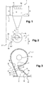
- a cyclone separator 1 As illustrated in Figure 1 and in Figure 2 , a cyclone separator 1 according to the invention comprises an inlet duct 2, a body portion 3 and a gas outlet tube 4.
- the inlet duct 2 through which a mixture of particles and gas enter the cyclone separator 1, may be a rectangular-shaped inlet flow passageway and usually extends partially into the upper portion of a fluidized bed combustion furnace.
- the inlet duct 2 comprises an intrados face 2a and an extrados face 2b.
- the intrados face 2a ends at the tip T of the cyclone separator 1.
- the inlet duct 2 is connected tangentially onto the cylindrical-shaped body portion or barrel portion 3 of the cyclone separator 1.
- the gas outlet tube 4 is a vortex finder that is connected to the body portion 3 at its upper end.
- the ratio d/D of the distance d between the parallel to the extrados face 2b dropped from the tip T of the cyclone separator 1 and the closest point of the gas outlet tube 4 to the internal diameter D of the body portion 3 is superior or equal to 0.1.
- Said distance d is measured at the lower extremity of the gas outlet tube 4, i.e. at the lower level 4a of the gas outlet tube 4.
- the second part of the intrados face 2a that ends at the tip T of the cyclone separator 1 is parallel to the extrados face 2b. It could be also envisaged that the second part of the intrados face 2a converges towards the extrados face 2b.
- Such a ratio d/D allows a high collection efficiency of fine particles. Indeed, the direct passage of the fine particles from the inlet duct 2 to the gas outlet tube 4 is avoided or remains very limited with such a ratio.
- the ratio d/D is preferably comprised between 0.1 and 0.15.
- the ratio d/D is less than 0.15 for an economical pressure drop solution.
- the ratio d/D is more preferably comprised between 0.11 and 0.13.
- the ratio s/S of the inlet duct area s, measured at the tip T of the cyclone separator 1 and perpendicularly to the extrados face 2b, to the cross-sectional area S of the body portion 3 is comprised between 0.24 and 0.32.
- Such a ratio s/S makes it possible to have a gas axial mean velocity in the body portion 3 that is higher than 7 m/s.
- the axial mean velocity can be defined as being the ratio of the gas volume flow to the cross-sectional area S of the body portion 3.
- the ratio s/S is higher to 0.24, in order to avoid any excessive pressure drop across the cyclone separator 1.
- the ratio s/S is less than 0.32, in order to allow a high velocity of the particles and to facilitate the respect of the d/D ratio.
- the ratio s/S is preferably comprised between 0.26 and 0.30, and more preferably between 0.27 and 0.29.
- the ratio of the height h of the inlet duct 2 to the width w of the inlet duct 2 at the tip T of the cyclone separator 1 does not exceed 4.
- This ratio allows an economical inlet duct.
- the height h of the inlet duct 2 is preferably not higher than the internal diameter D of the body portion 3, which limits the height of the cyclone body portion 3.
- the height H of the body portion 3 is preferably less than 1.2D, and more preferably less than 1.1D, D being the internal diameter of the body portion 3. This height is very advantageous since it provides low cyclone separator surface, weight and dimensions, which reduces the cost of the steel support structures. Moreover, the low height of the cyclone separator 1 facilitates the arrangement of a fluidized bed heat exchanger, if needed.
- the orifice of the vortex finder 4 is preferably not centred at the centre of the body portion 3.
- the distance I between the projection of the body portion 3 centre on a perpendicular to the extrados face 2b and the projection of the gas outlet tube 4 lower extremity centre on a perpendicular to the extrados face 2b can be comprised between 0.04D and 0.08D, D being the internal diameter of the body portion 2, as shown in Figure 2 .
- the ratio of the cross-sectional area a of the gas outlet tube 4 lower extremity to the cross-sectional area S of the body portion 3 can be comprised between 0.13 and 0.20, more preferably between 0.15 and 0.20.
- the gas outlet tube 4 can comprise a lower conical portion and an upper cylindrical portion.
- the gas outlet tube 4 can be designed at least partly conically, the inlet orifice of the gas outlet tube 4 having the lower section and the upper part of the gas outlet tube 4 being a cylinder with a greater section.
- the diameter (D v ) of the cylindrical portion and the diameter (d v ) at the lower part of the conical portion can be such that D v - d v ⁇ 0.3L, L being the height of the conical portion of the gas outlet tube 4.
- the inlet duct 2 can be an inlet duct disclosed in EP 1020229 , as shown in Figure 3 .
- the intrados face 2a ending at the tip T of the cyclone separator 1 said intrados face 2a which connects the starting point S of the inlet duct 2 to the point T at the tip of the cyclone separator 1 may have a profile such that it comprises at least two distinct tangents so that one D intersects the extrados face 2b at a point A located upstream of the foot B of the perpendicular to the extrados 2b taken from the tip T of the cyclone separator 1, and said intrados face 2a may start from said point S by a first part having a rectilinear profile R, followed by a second part having a curved profile V with a point of inflection 5 or else by a second rectilinear part which meets the tip T of the cyclone separator 1, said point S being located at the exit from the furnace.
- the intrados face 2a can have a first part having a rectilinear profile that is followed by a second rectilinear part and the rectilinear profile of the first part can make with the extrados face an angle comprised between 25° and 35°, as shown in Figure 2 .
- the pressure drop in the inlet duct 2 is reduced.
- the cyclone separator according to the invention accepts a body axial velocity of 8 to 10 m/s with same capture efficiency than proven current efficient cyclones operating at 5 to 6 m/s while keeping acceptable pressure losses. Moreover, an economical design is provided since the cyclone size is reduced.
- the cyclone separator is suitable for circulating fluidized bed boilers which are able to support the duty of separating solids that can be abrasive and which flow in a high amount of entrained solids compared to the gas flow (for instance for entrained solids quantity around or above 3 kg per m 3 gas).
- the cyclone separator can have a large flow capacity and may have an internal diameter of 5 m and more.
Landscapes
- Physics & Mathematics (AREA)
- Chemical & Material Sciences (AREA)
- Chemical Kinetics & Catalysis (AREA)
- Geometry (AREA)
- Fluid Mechanics (AREA)
- Cyclones (AREA)
Abstract
- a cylindrical-shaped body portion (3),
- an inlet duct (2) having an intrados face (2a) and an extrados face (2b), and which is connected to the body portion (3),
- a gas outlet tube (4) connected to the body portion (3) at its upper end, characterized in that:
- the ratio (d/D) of the distance (d) between the parallel to the extrados face (2b) dropped from the tip (T) of the cyclone separator (1) and the closest point of the gas outlet tube (4) to the internal diameter (D) of the body portion (3) is superior or equal to 0.1, said distance (d) being measured at the lower extremity (4a) of the gas outlet tube (4),
- the ratio (s/S) of the inlet duct area (s), measured at the tip (T) of the cyclone separator (1) and perpendicularly to the extrados face (2b), to the cross-sectional area (S) of the body portion (3), is comprised between 0.24 and 0.32, and
- the ratio (h/w) of the height (h) of the inlet duct (3) to the width (w) of the inlet duct (2) at the tip (T) of the cyclone separator (1) does not exceed 4.
Description
- The invention is related to a cyclone separator, and is more particularly directed to a cyclone separator for circulating fluidized bed (CFB) boilers.
- The circulating fluidized bed boilers require the capture of the particles that are entrained out of a reactor by reactor gases and their separation from the gases in order to recirculate it into said reactor for complete reaction.
- The separation is usually made by means of cyclone separators. Cyclonic separation is a method of removing particulates from gases, without the use of filters, through vortex separation. Rotational effects and gravity are used to separate mixtures of solids and gases.
- The capture efficiency of the smallest particles is a key issue.
- It is known that reducing the diameter of the cyclone separator thus increasing the axial mean velocity in the cyclone body while keeping the same similitude ratio leads to a strong increase of the pressure drop across the cyclone and finally to a decrease of the capture efficiency when trying to keep the pressure drop at a constant limited value by keeping nearly constant the inlet section of the gas-solids entrance into the cyclone. Such types of cyclones having a reduced shape ratio but a nearly constant inlet gas/solids entrance section dimensions to get the same pressure drop as the base cyclone operating at 6 m/s could be qualified as "similar" for the purpose of the comprehension.
- Most of the cyclone separators that are currently used in circulating fluidized bed boilers exhibit a good collection efficiency for body mean axial velocity of about 5 to 6 m/s. However, the "similar" cyclone separators, when used at a body mean axial velocity of above 7 m/s lead to a degraded capture efficiency. Thus, it is not possible to use "similar" cyclones if the cyclone collection efficiency of the cyclones operating at 8 m/s is required to be the same as the collection efficiency of the cyclones operating at 6 m/s and some changes have to be invented.
- Document
US 5,771,844 discloses a cyclone separator able to operate at a body mean axial velocity of 8 m/s with a capture efficiency which is similar to the efficiency of the cyclone separators that are efficient for an axial mean velocity of 6 m/s. -
US 5,771,844 discloses that the ratio height/depth of the opening of the cyclone separator inlet is at least 4/1. - This cyclone separator suffers the shortcoming that it makes the inlet duct more costly due to the stiffening needs of the unusually wide vertical dimension. In addition, the cyclone barrel is higher in order to locate the high vertical dimension of the opening. Thus, the cyclone separator body is more expensive than for lower ratios. Moreover, the total height of such a cyclone impacts detrimentally the arrangement of the whole system.
- An object of the present invention is to provide a cyclone separator in such a manner to solve the above described problems.
- The object mentioned above is accomplished by a cyclone separator for particle collection from a gas stream containing entrained solid particles, said cyclone separator comprising:
- a cylindrical-shaped body portion,
- an inlet duct having an intrados face and an extrados face, and which is connected to the body portion,
- a gas outlet tube connected to the body portion at its upper end. According to the invention:
- the ratio (d/D) of the distance (d) between the parallel to the extrados face dropped from the tip of the cyclone separator and the closest point of the gas outlet tube to the internal diameter (D) of the body portion is superior or equal to 0.1, said distance (d) being measured at the lower extremity of the gas outlet tube,
- the ratio (s/S) of the inlet duct area (s), measured at the tip of the cyclone separator and perpendicularly to the extrados face, to the cross-sectional area (S) of the body portion, is comprised between 0.24 and 0.32, and
- the ratio (h/w) of the height (h) of the inlet duct to the width (w) of the inlet duct at the tip of the cyclone separator does not exceed 4, and can be for instance less than 4.
- The ratio (d/D) of the distance (d) between the parallel to the extrados face dropped from the tip of the cyclone separator and the closest point of the gas outlet tube to the internal diameter (D) of the body portion is preferably comprised between 0.1 and 0.2, more preferably between 0.1 and 0.15 and even more preferably between 0.12 and 0.15.
- The ratio (h/w) of the height (h) of the inlet duct to the width (w) of the inlet duct at the tip of the cyclone separator is preferably comprised between 3 and 4, and more preferably between 3.5 and 4.
- For instance, different associations of the ratios d/D, s/S and h/w that can be carried out are mentioned in Table 1.
Table 1 d/D s/S h/w ≥0.1 0.24-0.32 ≤4 ≥0.1 0.26-0.30 or 0.27-0.29 ≤4 0.1-0.2 0.24-0.32 ≤4 0.1-0.2 0.26-0.30 or 0.27-0.29 ≤4 0.1-0.15 0.24-0.32 ≤4 0.1-0.15 0.26-0.30 or 0.27-0.29 ≤4 0.12-0.15 0.24-0.32 ≤4 0.12-0.15 0.26-0.30 or 0.27-0.29 ≤4 ≥0.1 0.24-0.32 3-4 ≥0.1 0.26-0.30 or 0.27-0.29 3-4 0.1-0.2 0.24-0.32 3-4 0.1-0.2 0.26-0.30 or 0.27-0.29 3-4 0.1-0.15 0.24-0.32 3-4 0.1-0.15 0.26-0.30 or 0.27-0.29 3-4 0.12-0.15 0.24-0.32 3-4 0.12-0.15 0.26-0.30 or 0.27-0.29 3-4 ≥0.1 0.24-0.32 3.5-4 ≥0.1 0.26-0.30 or 0.27-0.29 3.5-4 0.1-0.2 0.24-0.32 3.5-4 0.1-0.2 0.26-0.30 or 0.27-0.29 3.5-4 0.1-0.15 0.24-0.32 3.5-4 0.1-0.15 0.26-0.30 or 0.27-0.29 3.5-4 0.12-0.15 0.24-0.32 3.5-4 0.12-0.15 0.26-0.30 or 0.27-0.29 3.5-4 - The cyclone according to the invention avoids most of the direct leak of small particles from the cyclone entrance to the cyclone exit in the gas outlet tube, thus providing a good cyclone capture efficiency of small particles even for high mean gas axial velocity such as 8m/s and higher and allowing a reduction of the diameter of the body portion.
- The distance between the projection of the body portion centre on a perpendicular to the extrados face and the projection of the gas outlet tube lower extremity centre on a perpendicular to the extrados face can be comprised between 0.04D and 0.08D, D being the internal diameter of the body portion.
- The ratio (a/S) of the cross-sectional area (a) of the gas outlet tube lower extremity to the cross-sectional area (S) of the body portion can be comprised between 0.13 and 0.20, and more preferably between 0.15 and 0.20.
- Preferably, the height of the inlet duct does not exceed the internal diameter (D) of the body portion.
- The height of the body portion can be less than 1.2D, D being the internal diameter of the body portion.
- The gas outlet tube can comprise a lower conical portion and an upper cylindrical portion. The inlet orifice of the gas outlet tube can have a lower section than the section of the upper cylindrical portion of the gas outlet tube.
- The diameter (Dv) of the cylindrical portion and the diameter (dv) at the lower part of the conical portion can be such that 0 ≤ Dv - dv < 0.3L, L being the height of the conical portion of the gas outlet tube.
- The intrados face ending at the tip of the cyclone separator, said intrados face which connects the starting point of the inlet duct to the point at the tip of the cyclone separator can have a profile such that it comprises at least two distinct tangents so that one intersects the extrados face at a point located upstream of the foot of the perpendicular to the extrados face taken from the tip of the cyclone separator, and said intrados face can start from said point by a first part having a rectilinear profile, followed by a second part having a curved profile with a point of inflection or else by a second rectilinear part which meets the tip of the cyclone separator, said point being located at the exit from the furnace.
- The intrados face can have a first part having a rectilinear profile followed by a second rectilinear part and in that the rectilinear profile of the first part makes with the extrados face an angle comprised between 25° and 35° so as to procure a good compromise between separation efficiency (by projecting solids on the extrados face) and pressure drop.
- Other features and advantages of the invention will become apparent from the following description of embodiments of the invention given by way of non-limiting examples only, and with reference to the accompanying drawings, in which:
-
Figure 1 is a front view of a cyclone separator according to the invention, -
Figure 2 is a bottom view of the cyclone separator, and -
Figure 3 shows a cyclone separator according to the invention with a specific inlet duct. - As illustrated in
Figure 1 and inFigure 2 , acyclone separator 1 according to the invention comprises aninlet duct 2, abody portion 3 and agas outlet tube 4. - The
inlet duct 2, through which a mixture of particles and gas enter thecyclone separator 1, may be a rectangular-shaped inlet flow passageway and usually extends partially into the upper portion of a fluidized bed combustion furnace. Theinlet duct 2 comprises anintrados face 2a and anextrados face 2b. Theintrados face 2a ends at the tip T of thecyclone separator 1. - The
inlet duct 2 is connected tangentially onto the cylindrical-shaped body portion orbarrel portion 3 of thecyclone separator 1. - The
gas outlet tube 4 is a vortex finder that is connected to thebody portion 3 at its upper end. - According to the invention, the ratio d/D of the distance d between the parallel to the
extrados face 2b dropped from the tip T of thecyclone separator 1 and the closest point of thegas outlet tube 4 to the internal diameter D of thebody portion 3 is superior or equal to 0.1. Said distance d is measured at the lower extremity of thegas outlet tube 4, i.e. at thelower level 4a of thegas outlet tube 4. As shown inFigure 1 , the second part of theintrados face 2a that ends at the tip T of thecyclone separator 1 is parallel to theextrados face 2b. It could be also envisaged that the second part of theintrados face 2a converges towards theextrados face 2b. - Such a ratio d/D allows a high collection efficiency of fine particles. Indeed, the direct passage of the fine particles from the
inlet duct 2 to thegas outlet tube 4 is avoided or remains very limited with such a ratio. - The ratio d/D is preferably comprised between 0.1 and 0.15. The ratio d/D is less than 0.15 for an economical pressure drop solution. The ratio d/D is more preferably comprised between 0.11 and 0.13.
- Then, the ratio s/S of the inlet duct area s, measured at the tip T of the
cyclone separator 1 and perpendicularly to theextrados face 2b, to the cross-sectional area S of thebody portion 3 is comprised between 0.24 and 0.32. - Such a ratio s/S makes it possible to have a gas axial mean velocity in the
body portion 3 that is higher than 7 m/s. The axial mean velocity can be defined as being the ratio of the gas volume flow to the cross-sectional area S of thebody portion 3. - The ratio s/S is higher to 0.24, in order to avoid any excessive pressure drop across the
cyclone separator 1. The ratio s/S is less than 0.32, in order to allow a high velocity of the particles and to facilitate the respect of the d/D ratio. - The ratio s/S is preferably comprised between 0.26 and 0.30, and more preferably between 0.27 and 0.29.
- Last, the ratio of the height h of the
inlet duct 2 to the width w of theinlet duct 2 at the tip T of thecyclone separator 1 does not exceed 4. - This ratio allows an economical inlet duct.
- The height h of the
inlet duct 2 is preferably not higher than the internal diameter D of thebody portion 3, which limits the height of thecyclone body portion 3. - The height H of the
body portion 3 is preferably less than 1.2D, and more preferably less than 1.1D, D being the internal diameter of thebody portion 3. This height is very advantageous since it provides low cyclone separator surface, weight and dimensions, which reduces the cost of the steel support structures. Moreover, the low height of thecyclone separator 1 facilitates the arrangement of a fluidized bed heat exchanger, if needed. - In order to improve the cyclone separator efficiency, the orifice of the
vortex finder 4 is preferably not centred at the centre of thebody portion 3. Thus, the distance I between the projection of thebody portion 3 centre on a perpendicular to theextrados face 2b and the projection of thegas outlet tube 4 lower extremity centre on a perpendicular to theextrados face 2b can be comprised between 0.04D and 0.08D, D being the internal diameter of thebody portion 2, as shown inFigure 2 . - In order to improve the cyclone separator efficiency, the ratio of the cross-sectional area a of the
gas outlet tube 4 lower extremity to the cross-sectional area S of thebody portion 3 can be comprised between 0.13 and 0.20, more preferably between 0.15 and 0.20. - The
gas outlet tube 4 can comprise a lower conical portion and an upper cylindrical portion. Thus, the pressure drop in thegas outlet tube 4 is reduced compared to the pressure drop of a system having the same constant minimum section. Thegas outlet tube 4 can be designed at least partly conically, the inlet orifice of thegas outlet tube 4 having the lower section and the upper part of thegas outlet tube 4 being a cylinder with a greater section. In this case, the diameter (Dv) of the cylindrical portion and the diameter (dv) at the lower part of the conical portion can be such that Dv - dv < 0.3L, L being the height of the conical portion of thegas outlet tube 4. - The
inlet duct 2 can be an inlet duct disclosed inEP 1020229 , as shown inFigure 3 . For instance, theintrados face 2a ending at the tip T of thecyclone separator 1, saidintrados face 2a which connects the starting point S of theinlet duct 2 to the point T at the tip of thecyclone separator 1 may have a profile such that it comprises at least two distinct tangents so that one D intersects theextrados face 2b at a point A located upstream of the foot B of the perpendicular to theextrados 2b taken from the tip T of thecyclone separator 1, and saidintrados face 2a may start from said point S by a first part having a rectilinear profile R, followed by a second part having a curved profile V with a point ofinflection 5 or else by a second rectilinear part which meets the tip T of thecyclone separator 1, said point S being located at the exit from the furnace. - The
intrados face 2a can have a first part having a rectilinear profile that is followed by a second rectilinear part and the rectilinear profile of the first part can make with the extrados face an angle comprised between 25° and 35°, as shown inFigure 2 . Thus, the pressure drop in theinlet duct 2 is reduced. - The cyclone separator according to the invention accepts a body axial velocity of 8 to 10 m/s with same capture efficiency than proven current efficient cyclones operating at 5 to 6 m/s while keeping acceptable pressure losses. Moreover, an economical design is provided since the cyclone size is reduced. The cyclone separator is suitable for circulating fluidized bed boilers which are able to support the duty of separating solids that can be abrasive and which flow in a high amount of entrained solids compared to the gas flow (for instance for entrained solids quantity around or above 3 kg per m3 gas). The cyclone separator can have a large flow capacity and may have an internal diameter of 5 m and more.
Claims (10)
- A cyclone separator (1) for particle collection from a gas stream containing entrained solid particles, said cyclone separator (1) comprising:- a cylindrical-shaped body portion (3),- an inlet duct (2) having an intrados face (2a) and an extrados face (2b), and which is connected to the body portion (3),- a gas outlet tube (4) connected to the body portion (3) at its upper end,characterized in that:- the ratio (d/D) of the distance (d) between the parallel to the extrados face (2b) dropped from the tip of the cyclone separator (1) and the closest point of the gas outlet tube (4) to the internal diameter (D) of the body portion (3) is superior or equal to 0.1, said distance (d) being measured at the lower extremity (4a) of the gas outlet tube (4),- the ratio (s/S) of the inlet duct area (s), measured at the tip (T) of the cyclone separator (1) and perpendicularly to the extrados face (2b), to the cross-sectional area (S) of the body portion (3), is comprised between 0.24 and 0.32, and- the ratio (h/w) of the height (h) of the inlet duct (2) to the width (w) of the inlet duct at the tip (T) of the cyclone separator (1) does not exceed 4.
- The cyclone separator (1) according to claim 1, characterized in that the distance (I) between the projection of the body portion (3) centre on a perpendicular to the extrados face (2b) and the projection of the gas outlet tube (4) lower extremity centre on a perpendicular to the extrados face (2b) is comprised between 0.04D and 0.08D, D being the internal diameter of the body portion (3).
- The cyclone separator (1) according to claim 1 or 2, characterized in that the ratio (a/S) of the cross-sectional area (a) of the gas outlet tube (3) lower extremity to the cross-sectional area (S) of the body portion (3) is comprised between 0.13 and 0.20.
- The cyclone separator (1) according to any one of claims 1 to 3, characterized in that the height (h) of the inlet duct (2) does not exceed the internal diameter (D) of the body portion (3).
- The cyclone separator (1) according to any one of claims 1 to 4, characterized in that the height (H) of the body portion (3) is less than 1.2D, D being the internal diameter of the body portion (2).
- The cyclone separator (1) according to any one of claims 1 to 5, characterized in that the gas outlet tube (4) comprises a lower conical portion and an upper cylindrical portion.
- The cyclone separator (1) according to claim 6, characterized in that the inlet orifice of the gas outlet tube (4) has a lower section than the section of the upper cylindrical portion of the gas outlet tube (4).
- The cyclone separator (1) according to claim 6 or 7, characterized in that the diameter (Dv) of the cylindrical portion and the diameter (dv) at the lower part of the conical portion are such that 0 ≤ Dv - dv < 0.3L, L being the height of the conical portion of the gas outlet tube (4).
- The cyclone separator (1) according to any one of claims 1 to 8, characterized in that, the intrados face (2a) ending at the tip (T) of the cyclone separator (1), said intrados face (2a) which connects the starting point (S) of the inlet duct (2) to the point (T) at the tip of the cyclone separator (1) has a profile such that it comprises at least two distinct tangents so that one (D) intersects the extrados face (2b) at a point (A) located upstream of the foot (B) of the perpendicular to the extrados face (2b) taken from the tip of the cyclone separator (1), and in that said intrados face (2a) starts from said point (S) by a first part having a rectilinear profile (R) followed by a second part having a curved profile (V) with a point of inflection (5) or else by a second rectilinear part which meets the tip (T) of the cyclone separator (1), said point (S) being located at the exit from the furnace.
- The cyclone separator (1) according to any one of claims 1 to 9, characterized in that the intrados face (2a) has a first part having a rectilinear profile followed by a second rectilinear part and in that the rectilinear profile of the first part makes with the extrados face (2b) an angle comprised between 25° and 35°.
Priority Applications (7)
| Application Number | Priority Date | Filing Date | Title |
|---|---|---|---|
| PL10177470T PL2431096T3 (en) | 2010-09-17 | 2010-09-17 | Cyclone separator |
| EP10177470.1A EP2431096B1 (en) | 2010-09-17 | 2010-09-17 | Cyclone separator |
| PCT/US2011/048598 WO2012036845A1 (en) | 2010-09-17 | 2011-08-22 | Cyclone separator |
| US13/824,960 US9486727B2 (en) | 2010-09-17 | 2011-08-22 | Cyclone separator |
| MX2013003047A MX2013003047A (en) | 2010-09-17 | 2011-08-22 | Cyclone separator. |
| CN201180055461.3A CN103201099B (en) | 2010-09-17 | 2011-08-22 | cyclone separator |
| HRP20140268AT HRP20140268T1 (en) | 2010-09-17 | 2014-03-21 | Cyclone separator |
Applications Claiming Priority (1)
| Application Number | Priority Date | Filing Date | Title |
|---|---|---|---|
| EP10177470.1A EP2431096B1 (en) | 2010-09-17 | 2010-09-17 | Cyclone separator |
Publications (2)
| Publication Number | Publication Date |
|---|---|
| EP2431096A1 true EP2431096A1 (en) | 2012-03-21 |
| EP2431096B1 EP2431096B1 (en) | 2013-12-25 |
Family
ID=43589900
Family Applications (1)
| Application Number | Title | Priority Date | Filing Date |
|---|---|---|---|
| EP10177470.1A Active EP2431096B1 (en) | 2010-09-17 | 2010-09-17 | Cyclone separator |
Country Status (7)
| Country | Link |
|---|---|
| US (1) | US9486727B2 (en) |
| EP (1) | EP2431096B1 (en) |
| CN (1) | CN103201099B (en) |
| HR (1) | HRP20140268T1 (en) |
| MX (1) | MX2013003047A (en) |
| PL (1) | PL2431096T3 (en) |
| WO (1) | WO2012036845A1 (en) |
Cited By (1)
| Publication number | Priority date | Publication date | Assignee | Title |
|---|---|---|---|---|
| CN112944901A (en) * | 2021-01-28 | 2021-06-11 | 天津水泥工业设计研究院有限公司 | Suspension calcining modification furnace capable of reducing height and heat recovery system |
Families Citing this family (10)
| Publication number | Priority date | Publication date | Assignee | Title |
|---|---|---|---|---|
| EP2990123B1 (en) * | 2013-04-23 | 2018-07-04 | Shizuoka Plant Co., Ltd. | Cyclone device |
| CN103398375B (en) * | 2013-07-01 | 2016-01-13 | 中国华能集团清洁能源技术研究院有限公司 | With the cyclone separator of circulating fluidized bed boiler of wear-resisting target area and guider |
| EP2937867B1 (en) | 2014-03-03 | 2018-11-14 | Fnctech | Containment filtered venting system used for nuclear power plant |
| CN104235834B (en) * | 2014-09-24 | 2016-08-17 | 株洲火炬工业炉有限责任公司 | CFBB high-temperature separator |
| CN104624401B (en) * | 2015-03-06 | 2019-01-15 | 英尼奥斯欧洲股份公司 | Improved cyclone design |
| CN106287681A (en) * | 2016-01-18 | 2017-01-04 | 无锡华光锅炉股份有限公司 | A kind of separator inlet flue duct structure |
| US11634651B2 (en) * | 2016-09-08 | 2023-04-25 | Waste to Energy Systems, LLC | System and method for biogasification |
| CN106621468A (en) * | 2017-02-20 | 2017-05-10 | 福建龙净环保股份有限公司 | Vortex type grey water concentration separation device |
| CN107138266B (en) * | 2017-04-05 | 2024-01-16 | 厦门市三和泰科技有限公司 | Powder coating finished product collecting mechanism |
| CN120001547B (en) * | 2025-02-26 | 2025-11-21 | 南京林业大学 | Image acquisition system for multiple types of small-particle seeds based on suction cleaning |
Citations (5)
| Publication number | Priority date | Publication date | Assignee | Title |
|---|---|---|---|---|
| DE19606647A1 (en) * | 1995-03-18 | 1996-09-19 | Metallgesellschaft Ag | Cyclone assembly for high-temp sepn of solids from gases |
| US5771844A (en) | 1996-04-04 | 1998-06-30 | Foster Wheeler Development Corp. | Cyclone separator having increased gas flow capacity |
| EP1020229A1 (en) | 1999-01-18 | 2000-07-19 | ABB Alstom Power Combustion | Smoke inlet conduct for a cyclone |
| US20050126394A1 (en) * | 2002-03-19 | 2005-06-16 | Vince Reiling | Separation of gases and solids using a cyclone |
| US20060226055A1 (en) * | 2003-08-29 | 2006-10-12 | Oscar Castro Soto | Inlet head for a cyclone separator |
Family Cites Families (6)
| Publication number | Priority date | Publication date | Assignee | Title |
|---|---|---|---|---|
| CN2062412U (en) * | 1989-03-30 | 1990-09-19 | 东北电力学院 | Anti-abrasive device for boiler coal saver |
| FR2788454B1 (en) * | 1999-01-18 | 2001-02-23 | Alstom | SMOKE INLET SHEATH IN A CYCLONE SEPARATOR |
| US6322301B1 (en) * | 1999-11-17 | 2001-11-27 | Tindall Corporation | Device for transporting structures on a rail car |
| CN2434066Y (en) * | 2000-06-05 | 2001-06-13 | 中国石油化工集团公司 | Interception return volute cyclone separator arranged exhaust pipe with guide groove |
| EP1308213A1 (en) * | 2001-10-30 | 2003-05-07 | Alstom (Switzerland) Ltd | A centrifugal separator, in particular for a fluidized bed reactor device |
| DE102009050165A1 (en) * | 2009-10-21 | 2011-04-28 | Outotec Oyj | Device for the treatment of solids and / or gases |
-
2010
- 2010-09-17 EP EP10177470.1A patent/EP2431096B1/en active Active
- 2010-09-17 PL PL10177470T patent/PL2431096T3/en unknown
-
2011
- 2011-08-22 WO PCT/US2011/048598 patent/WO2012036845A1/en not_active Ceased
- 2011-08-22 CN CN201180055461.3A patent/CN103201099B/en not_active Expired - Fee Related
- 2011-08-22 US US13/824,960 patent/US9486727B2/en not_active Expired - Fee Related
- 2011-08-22 MX MX2013003047A patent/MX2013003047A/en active IP Right Grant
-
2014
- 2014-03-21 HR HRP20140268AT patent/HRP20140268T1/en unknown
Patent Citations (5)
| Publication number | Priority date | Publication date | Assignee | Title |
|---|---|---|---|---|
| DE19606647A1 (en) * | 1995-03-18 | 1996-09-19 | Metallgesellschaft Ag | Cyclone assembly for high-temp sepn of solids from gases |
| US5771844A (en) | 1996-04-04 | 1998-06-30 | Foster Wheeler Development Corp. | Cyclone separator having increased gas flow capacity |
| EP1020229A1 (en) | 1999-01-18 | 2000-07-19 | ABB Alstom Power Combustion | Smoke inlet conduct for a cyclone |
| US20050126394A1 (en) * | 2002-03-19 | 2005-06-16 | Vince Reiling | Separation of gases and solids using a cyclone |
| US20060226055A1 (en) * | 2003-08-29 | 2006-10-12 | Oscar Castro Soto | Inlet head for a cyclone separator |
Cited By (1)
| Publication number | Priority date | Publication date | Assignee | Title |
|---|---|---|---|---|
| CN112944901A (en) * | 2021-01-28 | 2021-06-11 | 天津水泥工业设计研究院有限公司 | Suspension calcining modification furnace capable of reducing height and heat recovery system |
Also Published As
| Publication number | Publication date |
|---|---|
| WO2012036845A1 (en) | 2012-03-22 |
| MX2013003047A (en) | 2013-08-01 |
| EP2431096B1 (en) | 2013-12-25 |
| HRP20140268T1 (en) | 2014-04-25 |
| PL2431096T3 (en) | 2014-05-30 |
| CN103201099B (en) | 2015-01-28 |
| US9486727B2 (en) | 2016-11-08 |
| US20130205731A1 (en) | 2013-08-15 |
| CN103201099A (en) | 2013-07-10 |
Similar Documents
| Publication | Publication Date | Title |
|---|---|---|
| EP2431096B1 (en) | Cyclone separator | |
| CN100571884C (en) | Multi-cyclone dust collector | |
| US6398973B1 (en) | Cyclone separator | |
| US10695775B1 (en) | Dual stage cyclone separator, dual stage cyclone separator assembly, and method of using same | |
| US5771844A (en) | Cyclone separator having increased gas flow capacity | |
| US7648544B2 (en) | Swirl tube separator | |
| JP2742669B2 (en) | Variable classification point cyclone | |
| JP2010534117A (en) | Cyclone with classifier inlet and small particle bypass | |
| CN209238196U (en) | Constant flow inlet device and cyclone separator | |
| CN111451008B (en) | Double-layer shell type high-efficiency cyclone separator | |
| CN110560276B (en) | Horizontal high-efficiency cyclone separator | |
| US10213794B1 (en) | Cyclone separator with flow altering baffles | |
| CN2551346Y (en) | Efficient cyclon separator | |
| EP1534437B1 (en) | Cyclone separator with a vortex extender pin | |
| US20040069705A1 (en) | Long free vortex, multi-compartment separation chamber cyclone apparatus | |
| CN109225689A (en) | A kind of tubular cyclones | |
| Hosien et al. | Effect of Solid Loading on the Performance of Gas-Solids Cyclone Separators. | |
| CN212263593U (en) | Double-layer shell type efficient cyclone separator | |
| CN108745667A (en) | Novel two stage cyclone separator and cleaning systems | |
| JPH05123609A (en) | Cyclone separator and power plant using the same | |
| CN110013911B (en) | Coarse slime aqueous medium sorting cyclone | |
| JP2002239418A (en) | Cyclone | |
| CN207857151U (en) | A kind of high efficiency low pressure drop cyclone separator | |
| CN201482586U (en) | Double cyclone vertical enrichment layer separator | |
| CN105214860A (en) | Gas solids two-phase multi-stage cyclone separator |
Legal Events
| Date | Code | Title | Description |
|---|---|---|---|
| PUAI | Public reference made under article 153(3) epc to a published international application that has entered the european phase |
Free format text: ORIGINAL CODE: 0009012 |
|
| AK | Designated contracting states |
Kind code of ref document: A1 Designated state(s): AL AT BE BG CH CY CZ DE DK EE ES FI FR GB GR HR HU IE IS IT LI LT LU LV MC MK MT NL NO PL PT RO SE SI SK SM TR |
|
| AX | Request for extension of the european patent |
Extension state: BA ME RS |
|
| 17P | Request for examination filed |
Effective date: 20120907 |
|
| GRAP | Despatch of communication of intention to grant a patent |
Free format text: ORIGINAL CODE: EPIDOSNIGR1 |
|
| INTG | Intention to grant announced |
Effective date: 20130912 |
|
| GRAS | Grant fee paid |
Free format text: ORIGINAL CODE: EPIDOSNIGR3 |
|
| GRAA | (expected) grant |
Free format text: ORIGINAL CODE: 0009210 |
|
| AK | Designated contracting states |
Kind code of ref document: B1 Designated state(s): AL AT BE BG CH CY CZ DE DK EE ES FI FR GB GR HR HU IE IS IT LI LT LU LV MC MK MT NL NO PL PT RO SE SI SK SM TR |
|
| REG | Reference to a national code |
Ref country code: GB Ref legal event code: FG4D |
|
| REG | Reference to a national code |
Ref country code: CH Ref legal event code: EP |
|
| REG | Reference to a national code |
Ref country code: AT Ref legal event code: REF Ref document number: 646291 Country of ref document: AT Kind code of ref document: T Effective date: 20140115 |
|
| REG | Reference to a national code |
Ref country code: IE Ref legal event code: FG4D |
|
| REG | Reference to a national code |
Ref country code: DE Ref legal event code: R096 Ref document number: 602010012618 Country of ref document: DE Effective date: 20140213 |
|
| REG | Reference to a national code |
Ref country code: HR Ref legal event code: TUEP Ref document number: P20140268 Country of ref document: HR |
|
| REG | Reference to a national code |
Ref country code: RO Ref legal event code: EPE |
|
| REG | Reference to a national code |
Ref country code: HR Ref legal event code: T1PR Ref document number: P20140268 Country of ref document: HR |
|
| PG25 | Lapsed in a contracting state [announced via postgrant information from national office to epo] |
Ref country code: LT Free format text: LAPSE BECAUSE OF FAILURE TO SUBMIT A TRANSLATION OF THE DESCRIPTION OR TO PAY THE FEE WITHIN THE PRESCRIBED TIME-LIMIT Effective date: 20131225 Ref country code: SE Free format text: LAPSE BECAUSE OF FAILURE TO SUBMIT A TRANSLATION OF THE DESCRIPTION OR TO PAY THE FEE WITHIN THE PRESCRIBED TIME-LIMIT Effective date: 20131225 Ref country code: NO Free format text: LAPSE BECAUSE OF FAILURE TO SUBMIT A TRANSLATION OF THE DESCRIPTION OR TO PAY THE FEE WITHIN THE PRESCRIBED TIME-LIMIT Effective date: 20140325 Ref country code: FI Free format text: LAPSE BECAUSE OF FAILURE TO SUBMIT A TRANSLATION OF THE DESCRIPTION OR TO PAY THE FEE WITHIN THE PRESCRIBED TIME-LIMIT Effective date: 20131225 |
|
| REG | Reference to a national code |
Ref country code: NL Ref legal event code: VDEP Effective date: 20131225 |
|
| REG | Reference to a national code |
Ref country code: AT Ref legal event code: MK05 Ref document number: 646291 Country of ref document: AT Kind code of ref document: T Effective date: 20131225 |
|
| REG | Reference to a national code |
Ref country code: LT Ref legal event code: MG4D |
|
| PG25 | Lapsed in a contracting state [announced via postgrant information from national office to epo] |
Ref country code: LV Free format text: LAPSE BECAUSE OF FAILURE TO SUBMIT A TRANSLATION OF THE DESCRIPTION OR TO PAY THE FEE WITHIN THE PRESCRIBED TIME-LIMIT Effective date: 20131225 |
|
| REG | Reference to a national code |
Ref country code: PL Ref legal event code: T3 |
|
| PG25 | Lapsed in a contracting state [announced via postgrant information from national office to epo] |
Ref country code: IS Free format text: LAPSE BECAUSE OF FAILURE TO SUBMIT A TRANSLATION OF THE DESCRIPTION OR TO PAY THE FEE WITHIN THE PRESCRIBED TIME-LIMIT Effective date: 20140425 Ref country code: BE Free format text: LAPSE BECAUSE OF FAILURE TO SUBMIT A TRANSLATION OF THE DESCRIPTION OR TO PAY THE FEE WITHIN THE PRESCRIBED TIME-LIMIT Effective date: 20131225 Ref country code: EE Free format text: LAPSE BECAUSE OF FAILURE TO SUBMIT A TRANSLATION OF THE DESCRIPTION OR TO PAY THE FEE WITHIN THE PRESCRIBED TIME-LIMIT Effective date: 20131225 |
|
| PG25 | Lapsed in a contracting state [announced via postgrant information from national office to epo] |
Ref country code: NL Free format text: LAPSE BECAUSE OF FAILURE TO SUBMIT A TRANSLATION OF THE DESCRIPTION OR TO PAY THE FEE WITHIN THE PRESCRIBED TIME-LIMIT Effective date: 20131225 Ref country code: CY Free format text: LAPSE BECAUSE OF FAILURE TO SUBMIT A TRANSLATION OF THE DESCRIPTION OR TO PAY THE FEE WITHIN THE PRESCRIBED TIME-LIMIT Effective date: 20131225 Ref country code: ES Free format text: LAPSE BECAUSE OF FAILURE TO SUBMIT A TRANSLATION OF THE DESCRIPTION OR TO PAY THE FEE WITHIN THE PRESCRIBED TIME-LIMIT Effective date: 20131225 Ref country code: AT Free format text: LAPSE BECAUSE OF FAILURE TO SUBMIT A TRANSLATION OF THE DESCRIPTION OR TO PAY THE FEE WITHIN THE PRESCRIBED TIME-LIMIT Effective date: 20131225 Ref country code: PT Free format text: LAPSE BECAUSE OF FAILURE TO SUBMIT A TRANSLATION OF THE DESCRIPTION OR TO PAY THE FEE WITHIN THE PRESCRIBED TIME-LIMIT Effective date: 20140428 Ref country code: SK Free format text: LAPSE BECAUSE OF FAILURE TO SUBMIT A TRANSLATION OF THE DESCRIPTION OR TO PAY THE FEE WITHIN THE PRESCRIBED TIME-LIMIT Effective date: 20131225 Ref country code: CZ Free format text: LAPSE BECAUSE OF FAILURE TO SUBMIT A TRANSLATION OF THE DESCRIPTION OR TO PAY THE FEE WITHIN THE PRESCRIBED TIME-LIMIT Effective date: 20131225 |
|
| REG | Reference to a national code |
Ref country code: DE Ref legal event code: R097 Ref document number: 602010012618 Country of ref document: DE |
|
| PG25 | Lapsed in a contracting state [announced via postgrant information from national office to epo] |
Ref country code: DK Free format text: LAPSE BECAUSE OF FAILURE TO SUBMIT A TRANSLATION OF THE DESCRIPTION OR TO PAY THE FEE WITHIN THE PRESCRIBED TIME-LIMIT Effective date: 20131225 |
|
| PLBE | No opposition filed within time limit |
Free format text: ORIGINAL CODE: 0009261 |
|
| STAA | Information on the status of an ep patent application or granted ep patent |
Free format text: STATUS: NO OPPOSITION FILED WITHIN TIME LIMIT |
|
| REG | Reference to a national code |
Ref country code: HU Ref legal event code: AG4A Ref document number: E020706 Country of ref document: HU |
|
| 26N | No opposition filed |
Effective date: 20140926 |
|
| REG | Reference to a national code |
Ref country code: DE Ref legal event code: R097 Ref document number: 602010012618 Country of ref document: DE Effective date: 20140926 |
|
| PG25 | Lapsed in a contracting state [announced via postgrant information from national office to epo] |
Ref country code: LU Free format text: LAPSE BECAUSE OF FAILURE TO SUBMIT A TRANSLATION OF THE DESCRIPTION OR TO PAY THE FEE WITHIN THE PRESCRIBED TIME-LIMIT Effective date: 20140917 Ref country code: MC Free format text: LAPSE BECAUSE OF FAILURE TO SUBMIT A TRANSLATION OF THE DESCRIPTION OR TO PAY THE FEE WITHIN THE PRESCRIBED TIME-LIMIT Effective date: 20131225 |
|
| REG | Reference to a national code |
Ref country code: CH Ref legal event code: PL |
|
| GBPC | Gb: european patent ceased through non-payment of renewal fee |
Effective date: 20140917 |
|
| PG25 | Lapsed in a contracting state [announced via postgrant information from national office to epo] |
Ref country code: SI Free format text: LAPSE BECAUSE OF FAILURE TO SUBMIT A TRANSLATION OF THE DESCRIPTION OR TO PAY THE FEE WITHIN THE PRESCRIBED TIME-LIMIT Effective date: 20131225 |
|
| REG | Reference to a national code |
Ref country code: IE Ref legal event code: MM4A |
|
| REG | Reference to a national code |
Ref country code: FR Ref legal event code: ST Effective date: 20150529 |
|
| PG25 | Lapsed in a contracting state [announced via postgrant information from national office to epo] |
Ref country code: LI Free format text: LAPSE BECAUSE OF NON-PAYMENT OF DUE FEES Effective date: 20140930 Ref country code: GB Free format text: LAPSE BECAUSE OF NON-PAYMENT OF DUE FEES Effective date: 20140917 Ref country code: CH Free format text: LAPSE BECAUSE OF NON-PAYMENT OF DUE FEES Effective date: 20140930 |
|
| PG25 | Lapsed in a contracting state [announced via postgrant information from national office to epo] |
Ref country code: FR Free format text: LAPSE BECAUSE OF NON-PAYMENT OF DUE FEES Effective date: 20140930 Ref country code: IE Free format text: LAPSE BECAUSE OF NON-PAYMENT OF DUE FEES Effective date: 20140917 |
|
| PG25 | Lapsed in a contracting state [announced via postgrant information from national office to epo] |
Ref country code: SM Free format text: LAPSE BECAUSE OF FAILURE TO SUBMIT A TRANSLATION OF THE DESCRIPTION OR TO PAY THE FEE WITHIN THE PRESCRIBED TIME-LIMIT Effective date: 20131225 |
|
| PG25 | Lapsed in a contracting state [announced via postgrant information from national office to epo] |
Ref country code: BG Free format text: LAPSE BECAUSE OF FAILURE TO SUBMIT A TRANSLATION OF THE DESCRIPTION OR TO PAY THE FEE WITHIN THE PRESCRIBED TIME-LIMIT Effective date: 20131225 Ref country code: MT Free format text: LAPSE BECAUSE OF FAILURE TO SUBMIT A TRANSLATION OF THE DESCRIPTION OR TO PAY THE FEE WITHIN THE PRESCRIBED TIME-LIMIT Effective date: 20131225 Ref country code: GR Free format text: LAPSE BECAUSE OF FAILURE TO SUBMIT A TRANSLATION OF THE DESCRIPTION OR TO PAY THE FEE WITHIN THE PRESCRIBED TIME-LIMIT Effective date: 20140326 Ref country code: IT Free format text: LAPSE BECAUSE OF FAILURE TO SUBMIT A TRANSLATION OF THE DESCRIPTION OR TO PAY THE FEE WITHIN THE PRESCRIBED TIME-LIMIT Effective date: 20131225 |
|
| REG | Reference to a national code |
Ref country code: DE Ref legal event code: R082 Ref document number: 602010012618 Country of ref document: DE Representative=s name: RUEGER | ABEL PATENT- UND RECHTSANWAELTE, DE Ref country code: DE Ref legal event code: R082 Ref document number: 602010012618 Country of ref document: DE Representative=s name: RUEGER ABEL PATENTANWAELTE PARTGMBB, DE Ref country code: DE Ref legal event code: R082 Ref document number: 602010012618 Country of ref document: DE Representative=s name: RUEGER, BARTHELT & ABEL, DE Ref country code: DE Ref legal event code: R081 Ref document number: 602010012618 Country of ref document: DE Owner name: GENERAL ELECTRIC TECHNOLOGY GMBH, CH Free format text: FORMER OWNER: ALSTOM TECHNOLOGY LTD., BADEN, CH Ref country code: DE Ref legal event code: R082 Ref document number: 602010012618 Country of ref document: DE Representative=s name: RUEGER ABEL PATENT- UND RECHTSANWAELTE, DE |
|
| REG | Reference to a national code |
Ref country code: HU Ref legal event code: HC9C Owner name: GENERAL ELECTRIC TECHNOLOGY GMBH, CH Free format text: FORMER OWNER(S): ALSTOM TECHNOLOGY LTD, CH |
|
| REG | Reference to a national code |
Ref country code: HR Ref legal event code: PNAN Ref document number: P20140268 Country of ref document: HR Owner name: GENERAL ELECTRIC TECHNOLOGY GMBH, CH |
|
| REG | Reference to a national code |
Ref country code: HR Ref legal event code: ODRP Ref document number: P20140268 Country of ref document: HR Payment date: 20170907 Year of fee payment: 8 |
|
| PGFP | Annual fee paid to national office [announced via postgrant information from national office to epo] |
Ref country code: HR Payment date: 20170907 Year of fee payment: 8 Ref country code: RO Payment date: 20170904 Year of fee payment: 8 |
|
| PGFP | Annual fee paid to national office [announced via postgrant information from national office to epo] |
Ref country code: HU Payment date: 20170911 Year of fee payment: 8 |
|
| PGFP | Annual fee paid to national office [announced via postgrant information from national office to epo] |
Ref country code: DE Payment date: 20170927 Year of fee payment: 8 |
|
| PG25 | Lapsed in a contracting state [announced via postgrant information from national office to epo] |
Ref country code: MK Free format text: LAPSE BECAUSE OF FAILURE TO SUBMIT A TRANSLATION OF THE DESCRIPTION OR TO PAY THE FEE WITHIN THE PRESCRIBED TIME-LIMIT Effective date: 20131225 |
|
| PG25 | Lapsed in a contracting state [announced via postgrant information from national office to epo] |
Ref country code: AL Free format text: LAPSE BECAUSE OF FAILURE TO SUBMIT A TRANSLATION OF THE DESCRIPTION OR TO PAY THE FEE WITHIN THE PRESCRIBED TIME-LIMIT Effective date: 20131225 |
|
| REG | Reference to a national code |
Ref country code: HR Ref legal event code: PBON Ref document number: P20140268 Country of ref document: HR Effective date: 20180917 |
|
| REG | Reference to a national code |
Ref country code: DE Ref legal event code: R119 Ref document number: 602010012618 Country of ref document: DE |
|
| PG25 | Lapsed in a contracting state [announced via postgrant information from national office to epo] |
Ref country code: DE Free format text: LAPSE BECAUSE OF NON-PAYMENT OF DUE FEES Effective date: 20190402 |
|
| PG25 | Lapsed in a contracting state [announced via postgrant information from national office to epo] |
Ref country code: RO Free format text: LAPSE BECAUSE OF NON-PAYMENT OF DUE FEES Effective date: 20180917 Ref country code: HU Free format text: LAPSE BECAUSE OF NON-PAYMENT OF DUE FEES Effective date: 20180918 Ref country code: HR Free format text: LAPSE BECAUSE OF NON-PAYMENT OF DUE FEES Effective date: 20180917 |
|
| PGFP | Annual fee paid to national office [announced via postgrant information from national office to epo] |
Ref country code: PL Payment date: 20210826 Year of fee payment: 12 |
|
| P01 | Opt-out of the competence of the unified patent court (upc) registered |
Effective date: 20230523 |
|
| PG25 | Lapsed in a contracting state [announced via postgrant information from national office to epo] |
Ref country code: PL Free format text: LAPSE BECAUSE OF NON-PAYMENT OF DUE FEES Effective date: 20220917 |
|
| PGFP | Annual fee paid to national office [announced via postgrant information from national office to epo] |
Ref country code: TR Payment date: 20250828 Year of fee payment: 16 |