EP2429157A2 - Controlling method, secondary unit and radio terminal equipment - Google Patents
Controlling method, secondary unit and radio terminal equipment Download PDFInfo
- Publication number
- EP2429157A2 EP2429157A2 EP11192343A EP11192343A EP2429157A2 EP 2429157 A2 EP2429157 A2 EP 2429157A2 EP 11192343 A EP11192343 A EP 11192343A EP 11192343 A EP11192343 A EP 11192343A EP 2429157 A2 EP2429157 A2 EP 2429157A2
- Authority
- EP
- European Patent Office
- Prior art keywords
- audio
- terminal equipment
- radio terminal
- connection
- secondary unit
- Prior art date
- Legal status (The legal status is an assumption and is not a legal conclusion. Google has not performed a legal analysis and makes no representation as to the accuracy of the status listed.)
- Granted
Links
- 238000000034 method Methods 0.000 title claims description 23
- 238000004891 communication Methods 0.000 claims abstract description 19
- 230000005236 sound signal Effects 0.000 claims abstract description 18
- 230000004044 response Effects 0.000 claims description 10
- 230000035945 sensitivity Effects 0.000 claims description 7
- 230000002093 peripheral effect Effects 0.000 description 10
- 230000001413 cellular effect Effects 0.000 description 6
- 230000008901 benefit Effects 0.000 description 3
- 230000006870 function Effects 0.000 description 2
- 230000007774 longterm Effects 0.000 description 2
- 238000005259 measurement Methods 0.000 description 2
- 238000010295 mobile communication Methods 0.000 description 2
- 238000004088 simulation Methods 0.000 description 2
- 230000005540 biological transmission Effects 0.000 description 1
- 238000006243 chemical reaction Methods 0.000 description 1
- 238000003384 imaging method Methods 0.000 description 1
- 230000011664 signaling Effects 0.000 description 1
Images
Classifications
-
- H—ELECTRICITY
- H04—ELECTRIC COMMUNICATION TECHNIQUE
- H04M—TELEPHONIC COMMUNICATION
- H04M1/00—Substation equipment, e.g. for use by subscribers
- H04M1/72—Mobile telephones; Cordless telephones, i.e. devices for establishing wireless links to base stations without route selection
- H04M1/724—User interfaces specially adapted for cordless or mobile telephones
- H04M1/72403—User interfaces specially adapted for cordless or mobile telephones with means for local support of applications that increase the functionality
- H04M1/72409—User interfaces specially adapted for cordless or mobile telephones with means for local support of applications that increase the functionality by interfacing with external accessories
- H04M1/72412—User interfaces specially adapted for cordless or mobile telephones with means for local support of applications that increase the functionality by interfacing with external accessories using two-way short-range wireless interfaces
-
- H—ELECTRICITY
- H04—ELECTRIC COMMUNICATION TECHNIQUE
- H04B—TRANSMISSION
- H04B7/00—Radio transmission systems, i.e. using radiation field
- H04B7/24—Radio transmission systems, i.e. using radiation field for communication between two or more posts
-
- H—ELECTRICITY
- H04—ELECTRIC COMMUNICATION TECHNIQUE
- H04M—TELEPHONIC COMMUNICATION
- H04M1/00—Substation equipment, e.g. for use by subscribers
- H04M1/60—Substation equipment, e.g. for use by subscribers including speech amplifiers
- H04M1/6025—Substation equipment, e.g. for use by subscribers including speech amplifiers implemented as integrated speech networks
-
- H—ELECTRICITY
- H04—ELECTRIC COMMUNICATION TECHNIQUE
- H04W—WIRELESS COMMUNICATION NETWORKS
- H04W88/00—Devices specially adapted for wireless communication networks, e.g. terminals, base stations or access point devices
- H04W88/02—Terminal devices
Definitions
- the invention relates to a method for controlling a communication system, the communication system comprising at least one unit of radio terminal equipment and one or more secondary units coupled to the radio terminal equipment.
- the invention also relates to a secondary unit and radio terminal equipment.
- Multipart radio terminals may include a cellular core unit and a number of optimised peripheral units.
- the peripheral units of the multipart radio terminals are optimised for specific tasks and the peripheral units are typically connected to a core unit by low-power radio frequency (LPRF) connections, such as Bluetooth connections.
- LPRF radio frequency
- One of the peripheral units may be optimised for making basic phone calls and another peripheral unit may be optimised for messaging and browsing or for imaging and music, for example.
- Typical mobile phones may also comprise several enhancement devices, such as headsets, pens, and web pads that communicate with the mobile phone over wireless connections.
- EP 1100249 discloses a method for optimizing audio response in voice over IP computer network systems. Call information is concerning gain and frequency characteristics response of the audio components of each participating computer is exchanged.
- US 2003/0131065 discloses emulating sound of a remote computer system, such as a server, on another computer system interfacing with the remote computer system via a network.
- Publication XP-002277008 defines requirements for Bluetooth devices necessary to support headset use case including remote audio volume control.
- the invention provides an improved method for controlling a communication system, the communication system comprising at least one unit of radio terminal equipment and one or more secondary units which secondary units are coupled to the radio terminal equipment, the method comprising: storing audio characteristic information determining audio modes in the at least one unit of radio terminal equipment, receiving information in the at least one unit of radio terminal equipment on an audio mode of a secondary unit, and setting audio properties of the secondary unit by the at least one unit of radio terminal equipment by using audio characteristic information corresponding to the informed audio mode.
- a method for controlling a communication system comprising at least one unit of radio terminal equipment and one or more secondary units which secondary units are coupled to the radio terminal equipment, the method comprising: storing audio characteristics information in a secondary unit, informing the at least one unit of radio terminal equipment on audio characteristics information optimising an audio signal of the secondary unit, converting the audio characteristics information into a form of an audio control algorithm used in the at least one unit of radio terminal equipment for performing a secondary unit audio control algorithm, and optimising an audio signal of the secondary unit by using the secondary unit audio control algorithm.
- a secondary unit suitable for being controlled by radio terminal equipment, the secondary unit comprising: means for defining an audio mode, and means for informing the radio terminal equipment on the audio mode.
- a secondary unit suitable for being controlled by radio terminal equipment, the secondary unit comprising: means for storing audio characteristics information, and means for informing the radio terminal equipment on audio characteristics information optimising an audio signal of the secondary unit.
- radio terminal equipment configured to communicate with one or more secondary units comprising: means for storing information on an audio mode or audio characteristic information determining audio modes, means for receiving information on an audio mode of a secondary unit optimising an audio signal of a secondary unit, and means for setting audio properties of the secondary unit by using the received information on the audio mode.
- radio terminal equipment configured to communicate with one or more secondary units, the radio terminal equipment comprising: means for receiving information on audio characteristics information determining audio modes optimising an audio signal of the secondary unit, means for converting the audio characteristics information into a form of an audio control algorithm used in the radio terminal equipment for performing a secondary unit audio control algorithm, and means for optimising an audio signal of the secondary unit by using the secondary unit audio control algorithm.
- the method and system of the invention provide several advantages.
- the radio system can be based on any transmission system, for example, GSM (Global System for Mobile Communications), WCDMA (Wideband Code Division Multiple Access) or CDMA (Code Division Multiple Access).
- GSM Global System for Mobile Communications
- WCDMA Wideband Code Division Multiple Access
- CDMA Code Division Multiple Access
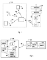
- a radio terminal equipment arrangement 90 in Figure 1 comprises radio terminal equipment 100 and a number of secondary units 102, 104, 112.
- the radio terminal equipment arrangement 90 is a multipart radio terminal, for example.
- the radio terminal equipment 100 may be a core unit of the multipart radio terminal, a typical mobile phone or a PDA (Personal Digital Assistant), for example.
- the core unit may have or may not have a user interface of its own.
- the secondary unit 102, 104, 112 may be another mobile phone or any accessory device that is used with the mobile phone, such as a headset 112. If the radio terminal equipment arrangement 90 is a multipart radio terminal, the secondary units 102, 104, 112 may be peripheral units communicating with the multipart radio terminal.
- the secondary unit may have wireless or wired connection to the multipart radio terminal equipment.
- Secondary units having audio characteristics may be classified into three main classes. First, there are secondary units (A) that cannot provide audio characterising information to radio terminal equipment, but they may communicate the desired audio mode (or an identifier) of the secondary unit. Terminal in this case uses preinstalled audio characterising information. The audio characterising information may be already located in the terminal before the secondary audio unit is connected. Secondary units of this class are suitable for the embodiment depicted with the aid of Figure 2 , for example.
- втори ⁇ н ⁇ е кон ⁇ е ком ⁇ онент B can provide audio characterising information to the radio terminal equipment in a connection establishment phase or any phase during the secondary unit connection.
- the downloaded information may be changed each time a connection is established.
- Secondary units (C) that may change their audio mode during the connection and that can provide new audio characterising information to the radio terminal equipment according to the secondary unit's current needs. These secondary units are sometimes called advanced secondary units. Secondary units of classes B and C are suitable for the embodiment depicted with the aid of Figure 3 , for instance.
- All these secondary units may be used as multipart peripheral units, accessories or enhancements.
- a cellular network may correspond to the combined structure of the GSM (Global System for Mobile Communications) and GPRS (General Packet Radio Service) systems, for example.
- GSM Global System for Mobile Communications
- GPRS General Packet Radio Service
- the GSM network elements are responsible for the implementation of circuit-switched connections
- the GPRS network elements are responsible for the implementation of packet-switched connections, some of the network elements, however, being shared by both systems.
- a centre 126 represents a mobile services switching centre (MSC) and a serving GPRS support node (SGSN) that enable circuit-switched and packet switched signalling, respectively, in the radio system.
- the cellular network may comprise a gateway unit 128, which is represented by a gateway mobile service switching centre (GMSC) and a gateway GPRS support node (GGSN).
- GMSC attends to the circuit-switched connections between the cellular network and external networks, such as a public land mobile network (PLMN) or a public switched telephone network (PSTN), and
- PLMN public land mobile network
- PSTN public switched telephone network
- GGSN attends to the packet-switched connections between the cellular network and external networks, such as the Internet.
- the centre 126 controls a radio access network (RAN) 120, which may comprise at least one base station controller 122 controlling at least one base station 124.
- the base station controller 122 can also be called a radio network controller, and the base station 124 can be called a node B.
- the radio terminal equipment 100 of the radio terminal equipment arrangement 90 may communicate with at least one base station 124 over a radio interface.
- the secondary units 102, 104, 112 in the radio terminal equipment arrangement 90 may be optimised for specific tasks.
- One of the secondary units is optimised for making basic phone calls and another secondary unit is optimised for messaging and browsing or for image processing and music, for example.
- Data may be stored in the secondary unit's own databases.
- the secondary units 102, 104, 112 communicate with the radio terminal equipment 100 with low-power radio frequency (LPRF) connections 106, 108, 110, such as Bluetooth or WLAN (Wireless Local Area Network) connections. It is also possible that a secondary unit uses wired connection such as USB (universal serial bus) or serial line connection.
- LPRF radio frequency
- the radio terminal equipment 100 is configured to communicate with other systems, such as the Internet, for example with LPRF connections and with GSM/GPRS/EDGE connections 114 as well. It is possible that the secondary units 102, 104 also communicate with other systems with GSM/GPRS/EDGE connections, for example. It is also possible that the secondary units 102, 104 are configured to establish outside LPRF connections, such as WLAN connections, to other systems. Also, the radio terminal equipment 100 may establish connections between the secondary units 102, 104 and other systems, such as the Internet or other radio terminals, via a cellular network by using a GSM or a GPRS/EDGE connection 114, for example.
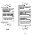
- FIG. 2 illustrates an embodiment of a method for controlling a communication system.
- the system of this embodiment comprises at least one unit of radio terminal equipment and one or more secondary units, which are coupled to the radio terminal equipment.
- the radio terminal equipment may be a core unit of a multipart radio terminal, a mobile phone or a PDA (Personal Digital Assistant), for example.
- a secondary unit may be another mobile phone or any accessory device used with the mobile phone having audio characteristics, such as a headset, a loudspeaker or a microphone. If the system is a multipart radio system, the secondary units are typically called peripheral units, accessories or enhancement devices.
- the method starts in block 200.
- audio characteristic information determining audio modes are stored in the radio terminal equipment. This can be done, for instance, in the secondary unit's connecting phase.
- the audio modes can be determined in many different ways.
- One example is to use at least one handsfree mode, at least one handportable mode and at least one wired headset mode.
- the audio characteristics are adjusted to optimise the quality of the audio signal.
- Audio parameters are, for example, parameters concerning sensitivity, frequency response, echo cancellation, dynamics control and/or noise cancellation in both downlink and uplink direction. The parameters may be determined, for instance, on the basis of simulations, measurements and/or long-term practical experience.
- One benefit achieved by storing the parameters determining audio modes in the radio terminal equipment is that there is no need to have a memory unit in a secondary unit, and the message adjusting the audio characteristics can be relatively short, containing only the audio modes.
- the radio terminal equipment is informed of an audio mode of a secondary unit.
- the information is typically conveyed by a message containing information on the audio mode needed by a secondary unit.
- the message is conveyed via a connection, the connection being for instance a radio connection, an infrared connection or a galvanic connection.
- the information on audio mode can be ciphered while conveyed between the secondary unit and the radio terminal equipment.
- audio properties of the secondary unit are set by the radio terminal equipment using the audio characteristic information corresponding the informed audio mode.
- the information about the audio mode required by the secondary unit has been transmitted and the radio terminal equipment controls the audio characteristics of the secondary unit by using the parameters stored in its memory, which correspond to the informed audio mode.
- the controlling is carried out by using the connection between the radio terminal equipment and the secondary unit. The purpose is to optimise the quality of an audio signal.
- the embodiment ends in block 208.
- Arrow 210 depicts one possibility for repeating the embodiment.
- FIG. 3 illustrates another embodiment of a method for controlling a communication system.
- the system of this embodiment comprises at least one unit of radio terminal equipment and one or more secondary units, which are coupled to the radio terminal equipment.
- the radio terminal equipment may be the core unit of a multipart radio terminal, a mobile phone or a PDA (Personal Digital Assistant), for example.
- a secondary unit may be another mobile phone or any accessory device used with the mobile phone having audio characteristics, such as a headset, a loudspeaker, a transducer or a microphone. If the system is a multipart radio system, the secondary units are typically called peripheral units, accessories or enhancement devices.
- the method starts in block 300.
- audio characteristics information is stored in a secondary unit.
- the audio characteristics information may include, for example parameters concerning sensitivity, frequency response, echo cancellation, dynamics control and/or noise cancellation or an audio routing mode, such as mono sound, stereo sound, handsfree or handset mode in uplink and/or downlink direction.
- the audio parameters may be determined, for instance, on the basis of simulations, acoustical measurements and/or long-term practical experience.
- One benefit achieved by storing the audio characteristics information in the secondary unit is that it is possible to use radio terminal equipment, which does not originally have required characteristics, such as software or memory capacity, as a core unit of a multipart system.
- the radio terminal equipment is informed of the audio characteristics information optimising the audio signal of the secondary unit.
- the information is typically conveyed by a message containing information on the audio characteristics needed by the secondary unit.
- the message is transmitted via a connection, the connection being for instance a radio connection, an infrared connection or a galvanic connection.
- the audio characteristics information can be ciphered while conveyed between the secondary unit and the radio terminal equipment.
- the audio characteristics information is converted into a form of an audio control algorithm used in the radio terminal equipment for performing a secondary unit audio control algorithm.
- a suitable analogue or digital signal gain can be calculated from sensitivity information in such a way that an appropriate volume level can be achieved or frequency response information can be used to create an equalizer to obtain target frequency response, and an echo canceller can be initialised with echo canceller information.
- an audio signal of the secondary unit is optimised by using the secondary unit audio control algorithm.
- the radio terminal equipment 100 is configured to communicate with one or more secondary units 102 by using wireless low-power radio frequency (LPRF) connections 106.
- the radio connection 106 is established by a transceiver 404. Via the transceiver 404, the radio terminal equipment receives information on an audio mode or audio characterising information.
- the radio terminal equipment 100 comprises at least a control unit 400 for controlling the functions of the radio terminal equipment 100.
- the control unit 400 is responsible for adjusting audio characteristics of determined secondary units.
- the radio terminal equipment 100 may also comprise, for example, the following elements: a memory 408 for storing data, such as information on an audio mode or audio characteristic information determining audio modes, a communications subsystem 402, and a user interface 406.
- the communications subsystem 402 controls the communication of the radio terminal equipment 100.
- the user interface 406 of the radio terminal equipment 100 is an interface via which the user can interact with the software of the radio terminal equipment 100 and also with the secondary unit 102.
- the user interface 406 may comprise, for instance, a display, a loudspeaker and a keypad part. Depending on the type of a device, there may be different user interface parts and a varying number of them.
- the secondary unit 102 may correspondingly comprise a transceiver 410 for communicating with the radio terminal equipment 100, a control unit 412 for controlling the functions of the secondary unit 102, and a memory unit 414 for storing different data, such as audio characteristics information.
- the radio terminal equipment 100 does not typically have a user interface of its own.
- a user communicates with the system via a user interface located in a secondary device(s).
- the radio terminal equipment 100 has some kind of user interface.
- the user may communicate with the system either via the terminal equipment 100 or the secondary device(s) 102.
- the control unit 412 may define an audio mode and control message conveying. For example, a user opens the cover of a secondary unit 102, the control unit 412 recognises it and commands the transceiver 410 to send a message to the radio terminal equipment 100, informing about the required audio mode.
- the control units 400, 412 of the radio terminal equipment 100 and the secondary unit 102 refer to blocks controlling the operation of the devices and are typically implemented as a processor and software, but different hardware implementations are also feasible, e.g. a circuit built of separate logics components or one or more client-specific integrated circuits (Application-Specific Integrated Circuit, ASIC). A hybrid of these implementations is also feasible.
Landscapes
- Engineering & Computer Science (AREA)
- Computer Networks & Wireless Communication (AREA)
- Signal Processing (AREA)
- Human Computer Interaction (AREA)
- Telephone Function (AREA)
- Mobile Radio Communication Systems (AREA)
- Circuit For Audible Band Transducer (AREA)
- Transceivers (AREA)
Abstract
Description
- The invention relates to a method for controlling a communication system, the communication system comprising at least one unit of radio terminal equipment and one or more secondary units coupled to the radio terminal equipment. The invention also relates to a secondary unit and radio terminal equipment.
- Mobile devices divided into several parts that are used in various combinations are being developed. Multipart radio terminals, for example, may include a cellular core unit and a number of optimised peripheral units. The peripheral units of the multipart radio terminals are optimised for specific tasks and the peripheral units are typically connected to a core unit by low-power radio frequency (LPRF) connections, such as Bluetooth connections. One of the peripheral units may be optimised for making basic phone calls and another peripheral unit may be optimised for messaging and browsing or for imaging and music, for example. Typical mobile phones may also comprise several enhancement devices, such as headsets, pens, and web pads that communicate with the mobile phone over wireless connections.
- Since there are many different kinds of peripheral units or usage modes, the audio characteristics of the system need to be adjusted as smooth and flexible as possible.
-
EP 1100249 discloses a method for optimizing audio response in voice over IP computer network systems. Call information is concerning gain and frequency characteristics response of the audio components of each participating computer is exchanged. -
US 2003/0131065 discloses emulating sound of a remote computer system, such as a server, on another computer system interfacing with the remote computer system via a network. - Publication XP-002277008 defines requirements for Bluetooth devices necessary to support headset use case including remote audio volume control.
- The invention provides an improved method for controlling a communication system, the communication system comprising at least one unit of radio terminal equipment and one or more secondary units which secondary units are coupled to the radio terminal equipment, the method comprising: storing audio characteristic information determining audio modes in the at least one unit of radio terminal equipment, receiving information in the at least one unit of radio terminal equipment on an audio mode of a secondary unit, and setting audio properties of the secondary unit by the at least one unit of radio terminal equipment by using audio characteristic information corresponding to the informed audio mode.
- According to another embodiment, there is provided a method for controlling a communication system, the communication system comprising at least one unit of radio terminal equipment and one or more secondary units which secondary units are coupled to the radio terminal equipment, the method comprising: storing audio characteristics information in a secondary unit, informing the at least one unit of radio terminal equipment on audio characteristics information optimising an audio signal of the secondary unit, converting the audio characteristics information into a form of an audio control algorithm used in the at least one unit of radio terminal equipment for performing a secondary unit audio control algorithm, and optimising an audio signal of the secondary unit by using the secondary unit audio control algorithm.
- According to another embodiment, there is provided a secondary unit suitable for being controlled by radio terminal equipment, the secondary unit comprising: means for defining an audio mode, and means for informing the radio terminal equipment on the audio mode.
- According to another embodiment, there is provided a secondary unit suitable for being controlled by radio terminal equipment, the secondary unit comprising: means for storing audio characteristics information, and means for informing the radio terminal equipment on audio characteristics information optimising an audio signal of the secondary unit.
- According to another embodiment, there is provided radio terminal equipment configured to communicate with one or more secondary units comprising: means for storing information on an audio mode or audio characteristic information determining audio modes, means for receiving information on an audio mode of a secondary unit optimising an audio signal of a secondary unit, and means for setting audio properties of the secondary unit by using the received information on the audio mode.
- According to another embodiment, there is provided radio terminal equipment configured to communicate with one or more secondary units, the radio terminal equipment comprising: means for receiving information on audio characteristics information determining audio modes optimising an audio signal of the secondary unit, means for converting the audio characteristics information into a form of an audio control algorithm used in the radio terminal equipment for performing a secondary unit audio control algorithm, and means for optimising an audio signal of the secondary unit by using the secondary unit audio control algorithm.
- The method and system of the invention provide several advantages. In one embodiment of the invention, it is possible to use radio terminal equipment, which does not originally have required characteristics, such as software or memory capacity, as a core unit of a multipart system. In another embodiment, there is no need to have a memory unit in a secondary unit, and the message adjusting the audio characteristics can be relatively short, containing only the audio modes.
- In the following, embodiments of the invention will be described in greater detail with reference to preferred embodiments and the accompanying drawings, in which
-
Figure 1 shows an example of a structure of a radio system and a radio terminal equipment arrangement according to an embodiment of the invention; -
Figure 2 illustrates an example of a method to control a communication system; -
Figure 3 illustrates another example of a method to control a communication system; -
Figure 4 shows an example of radio terminal equipment and a secondary unit. - With reference to
Figure 1 , let us examine an example of a radio system to which the preferred embodiments of the invention can be applied. The radio system can be based on any transmission system, for example, GSM (Global System for Mobile Communications), WCDMA (Wideband Code Division Multiple Access) or CDMA (Code Division Multiple Access). - A radio
terminal equipment arrangement 90 inFigure 1 comprisesradio terminal equipment 100 and a number ofsecondary units terminal equipment arrangement 90 is a multipart radio terminal, for example. Theradio terminal equipment 100, on the other hand, may be a core unit of the multipart radio terminal, a typical mobile phone or a PDA (Personal Digital Assistant), for example. The core unit may have or may not have a user interface of its own. Thesecondary unit headset 112. If the radioterminal equipment arrangement 90 is a multipart radio terminal, thesecondary units Figure 2 , for example. - Second, there are secondary units (B) that can provide audio characterising information to the radio terminal equipment in a connection establishment phase or any phase during the secondary unit connection. For example, the downloaded information may be changed each time a connection is established.
- Third, there are secondary units (C) that may change their audio mode during the connection and that can provide new audio characterising information to the radio terminal equipment according to the secondary unit's current needs. These secondary units are sometimes called advanced secondary units. Secondary units of classes B and C are suitable for the embodiment depicted with the aid of
Figure 3 , for instance. - All these secondary units may be used as multipart peripheral units, accessories or enhancements.
- A cellular network may correspond to the combined structure of the GSM (Global System for Mobile Communications) and GPRS (General Packet Radio Service) systems, for example. The GSM network elements are responsible for the implementation of circuit-switched connections, and the GPRS network elements are responsible for the implementation of packet-switched connections, some of the network elements, however, being shared by both systems.
- A
centre 126 represents a mobile services switching centre (MSC) and a serving GPRS support node (SGSN) that enable circuit-switched and packet switched signalling, respectively, in the radio system. The cellular network may comprise agateway unit 128, which is represented by a gateway mobile service switching centre (GMSC) and a gateway GPRS support node (GGSN). GMSC attends to the circuit-switched connections between the cellular network and external networks, such as a public land mobile network (PLMN) or a public switched telephone network (PSTN), and GGSN attends to the packet-switched connections between the cellular network and external networks, such as the Internet. - The
centre 126 controls a radio access network (RAN) 120, which may comprise at least onebase station controller 122 controlling at least onebase station 124. Thebase station controller 122 can also be called a radio network controller, and thebase station 124 can be called a node B. Theradio terminal equipment 100 of the radioterminal equipment arrangement 90 may communicate with at least onebase station 124 over a radio interface. - The
secondary units terminal equipment arrangement 90 may be optimised for specific tasks. One of the secondary units is optimised for making basic phone calls and another secondary unit is optimised for messaging and browsing or for image processing and music, for example. Data may be stored in the secondary unit's own databases. Thesecondary units terminal equipment 100 with low-power radio frequency (LPRF)connections radio terminal equipment 100, on the other hand, is configured to communicate with other systems, such as the Internet, for example with LPRF connections and with GSM/GPRS/EDGE connections 114 as well. It is possible that thesecondary units secondary units radio terminal equipment 100 may establish connections between thesecondary units EDGE connection 114, for example. -
Figure 2 illustrates an embodiment of a method for controlling a communication system. The system of this embodiment comprises at least one unit of radio terminal equipment and one or more secondary units, which are coupled to the radio terminal equipment. The radio terminal equipment may be a core unit of a multipart radio terminal, a mobile phone or a PDA (Personal Digital Assistant), for example. A secondary unit may be another mobile phone or any accessory device used with the mobile phone having audio characteristics, such as a headset, a loudspeaker or a microphone. If the system is a multipart radio system, the secondary units are typically called peripheral units, accessories or enhancement devices. The method starts inblock 200. Inblock 202, audio characteristic information determining audio modes are stored in the radio terminal equipment. This can be done, for instance, in the secondary unit's connecting phase. The audio modes can be determined in many different ways. One example is to use at least one handsfree mode, at least one handportable mode and at least one wired headset mode. In each mode, the audio characteristics are adjusted to optimise the quality of the audio signal. Audio parameters are, for example, parameters concerning sensitivity, frequency response, echo cancellation, dynamics control and/or noise cancellation in both downlink and uplink direction. The parameters may be determined, for instance, on the basis of simulations, measurements and/or long-term practical experience. - One benefit achieved by storing the parameters determining audio modes in the radio terminal equipment is that there is no need to have a memory unit in a secondary unit, and the message adjusting the audio characteristics can be relatively short, containing only the audio modes.
- In
block 204, the radio terminal equipment is informed of an audio mode of a secondary unit. The information is typically conveyed by a message containing information on the audio mode needed by a secondary unit. The message is conveyed via a connection, the connection being for instance a radio connection, an infrared connection or a galvanic connection. The information on audio mode can be ciphered while conveyed between the secondary unit and the radio terminal equipment. - In
block 206, audio properties of the secondary unit are set by the radio terminal equipment using the audio characteristic information corresponding the informed audio mode. In other words, for example, the information about the audio mode required by the secondary unit has been transmitted and the radio terminal equipment controls the audio characteristics of the secondary unit by using the parameters stored in its memory, which correspond to the informed audio mode. The controlling is carried out by using the connection between the radio terminal equipment and the secondary unit. The purpose is to optimise the quality of an audio signal. - Attention should be paid to the fact that similar secondary units, such as different stereo headset types, may have different audio characteristics or properties. Thus audio characteristics or properties depend on the type of the secondary unit in question.
- The embodiment ends in
block 208.Arrow 210 depicts one possibility for repeating the embodiment. -
Figure 3 illustrates another embodiment of a method for controlling a communication system. The system of this embodiment comprises at least one unit of radio terminal equipment and one or more secondary units, which are coupled to the radio terminal equipment. The radio terminal equipment may be the core unit of a multipart radio terminal, a mobile phone or a PDA (Personal Digital Assistant), for example. A secondary unit may be another mobile phone or any accessory device used with the mobile phone having audio characteristics, such as a headset, a loudspeaker, a transducer or a microphone. If the system is a multipart radio system, the secondary units are typically called peripheral units, accessories or enhancement devices. The method starts inblock 300. - In
block 302, audio characteristics information is stored in a secondary unit. The audio characteristics information may include, for example parameters concerning sensitivity, frequency response, echo cancellation, dynamics control and/or noise cancellation or an audio routing mode, such as mono sound, stereo sound, handsfree or handset mode in uplink and/or downlink direction. The audio parameters may be determined, for instance, on the basis of simulations, acoustical measurements and/or long-term practical experience. - One benefit achieved by storing the audio characteristics information in the secondary unit is that it is possible to use radio terminal equipment, which does not originally have required characteristics, such as software or memory capacity, as a core unit of a multipart system.
- In
block 304, the radio terminal equipment is informed of the audio characteristics information optimising the audio signal of the secondary unit. The information is typically conveyed by a message containing information on the audio characteristics needed by the secondary unit. The message is transmitted via a connection, the connection being for instance a radio connection, an infrared connection or a galvanic connection. The audio characteristics information can be ciphered while conveyed between the secondary unit and the radio terminal equipment. - In
block 306, the audio characteristics information is converted into a form of an audio control algorithm used in the radio terminal equipment for performing a secondary unit audio control algorithm. In the conversion, for example a suitable analogue or digital signal gain can be calculated from sensitivity information in such a way that an appropriate volume level can be achieved or frequency response information can be used to create an equalizer to obtain target frequency response, and an echo canceller can be initialised with echo canceller information. - In
block 308, an audio signal of the secondary unit is optimised by using the secondary unit audio control algorithm. - Attention should be paid to the fact that similar secondary units, such as different stereo head set types, may have different audio characteristics or properties. Thus audio characteristics or properties depend on the type of the secondary unit in question. The embodiment ends in
block 310.Arrow 312 depicts one possibility for repeating the embodiment. - A generalised example of radio equipment and a secondary unit is depicted in
Figure 4 . Theradio terminal equipment 100 is configured to communicate with one or moresecondary units 102 by using wireless low-power radio frequency (LPRF)connections 106. Theradio connection 106 is established by atransceiver 404. Via thetransceiver 404, the radio terminal equipment receives information on an audio mode or audio characterising information. In the example ofFigure 4 , theradio terminal equipment 100 comprises at least acontrol unit 400 for controlling the functions of theradio terminal equipment 100. Thecontrol unit 400 is responsible for adjusting audio characteristics of determined secondary units. Theradio terminal equipment 100 may also comprise, for example, the following elements: amemory 408 for storing data, such as information on an audio mode or audio characteristic information determining audio modes, acommunications subsystem 402, and auser interface 406. - The
communications subsystem 402 controls the communication of theradio terminal equipment 100. Theuser interface 406 of theradio terminal equipment 100 is an interface via which the user can interact with the software of theradio terminal equipment 100 and also with thesecondary unit 102. Theuser interface 406 may comprise, for instance, a display, a loudspeaker and a keypad part. Depending on the type of a device, there may be different user interface parts and a varying number of them. - The
secondary unit 102 may correspondingly comprise atransceiver 410 for communicating with theradio terminal equipment 100, acontrol unit 412 for controlling the functions of thesecondary unit 102, and amemory unit 414 for storing different data, such as audio characteristics information. - In a multipart concept, the
radio terminal equipment 100 does not typically have a user interface of its own. A user communicates with the system via a user interface located in a secondary device(s). - It is still possible, however, that also the
radio terminal equipment 100 has some kind of user interface. In that case, the user may communicate with the system either via theterminal equipment 100 or the secondary device(s) 102. - The
control unit 412 may define an audio mode and control message conveying. For example, a user opens the cover of asecondary unit 102, thecontrol unit 412 recognises it and commands thetransceiver 410 to send a message to theradio terminal equipment 100, informing about the required audio mode. - The
control units radio terminal equipment 100 and thesecondary unit 102 refer to blocks controlling the operation of the devices and are typically implemented as a processor and software, but different hardware implementations are also feasible, e.g. a circuit built of separate logics components or one or more client-specific integrated circuits (Application-Specific Integrated Circuit, ASIC). A hybrid of these implementations is also feasible. - Even though the invention is described above with reference to an example according to the accompanying drawings, it is clear that the invention is not restricted thereto but it can be modified in several ways within the scope of the appended claims.
Claims (17)
- A method for controlling a communication system, the communication system comprising at least one unit of radio terminal equipment and one or more secondary units which secondary units are coupled to the radio terminal equipment, the method comprising:storing (202) audio characteristic information determining audio modes in the at least one unit of radio terminal equipment;receiving (204) information in the at least one unit of radio terminal equipment on an audio mode of a secondary unit, andsetting (206) audio properties of the secondary unit by the at least one unit of radio terminal equipment by using audio characteristic information corresponding to the informed audio mode.
- A method for controlling a communication system, the communication system comprising at least one unit of radio terminal equipment and one or more secondary units which secondary units are coupled to the radio terminal equipment, the method comprising:storing (302) audio characteristics information in a secondary unit;informing (304) the at least one unit of radio terminal equipment on audio characteristics information optimising an audio signal of the secondary unit;converting (306) the audio characteristics information into a form of an audio control algorithm used in the at least one unit of radio terminal equipment for performing a secondary unit audio control algorithm, andoptimising (308) an audio signal of the secondary unit by using the secondary unit audio control algorithm.
- The method of claim 1, wherein the audio characteristic information comprises information concerning at least one of: sensitivity, frequency response, echo cancellation, dynamics control and noise cancellation.
- The method of claim 2, wherein the audio characteristics information comprises information concerning sensitivity, frequency response, echo cancellation, dynamics control, noise cancellation or an audio routing mode.
- The method of claim 1, wherein the radio terminal equipment is informed of the audio mode via a connection, the connection comprising a radio connection, an infrared connection or a galvanic connection.
- The method of claim 2, wherein the radio terminal equipment is informed of the audio characteristics information via a connection, the connection comprising a radio connection, an infrared connection or a galvanic connection.
- The method of claim 2, wherein the audio characteristics information is ciphered while conveyed between the secondary unit and the radio terminal equipment.
- A secondary unit suitable for being controlled by radio terminal equipment, the secondary unit comprising:means (412) for defining an audio mode, andmeans (410, 412) for informing the radio terminal equipment on the audio mode.
- A secondary unit suitable for being controlled by radio terminal equipment, the secondary unit comprising:means (414) for storing audio characteristics information, andmeans (410, 412) for informing the radio terminal equipment on audio characteristics information optimising an audio signal of the secondary unit.
- The secondary unit of claim 9, wherein the audio characteristics information comprises parameters concerning at least one of: sensitivity, frequency response, echo cancellation, dynamics control, noise cancellation or an audio routing mode.
- The secondary unit of claim 8, wherein the radio terminal equipment is informed on the audio mode via a connection, the connection comprising a radio connection, an infrared connection or a galvanic connection.
- The secondary unit of claim 9, wherein the radio terminal equipment is informed of the audio characteristics information via a connection, the connection comprising a radio connection, an infrared connection or a galvanic connection.
- Radio terminal equipment configured to communicate with one or more secondary units comprising:means for (408) storing information on an audio mode or audio characteristic information determining audio modes;means (404) for receiving information on an audio mode of a secondary unit optimising an audio signal of a secondary unit, andmeans (400) for setting audio properties of the secondary unit by using the received information on the audio mode.
- Radio terminal equipment configured to communicate with one or more secondary units, the radio terminal equipment comprising:means for (404) receiving information on audio characteristics information determining audio modes optimising an audio signal of the secondary unit;means for (400) converting the audio characteristics information into a form of an audio control algorithm used in the radio terminal equipment for performing a secondary unit audio control algorithm, andmeans for (400) optimising an audio signal of the secondary unit by using the secondary unit audio control algorithm.
- The radio terminal equipment of claim 14, wherein the audio characteristic information comprise parameters concerning at least one of:sensitivity, frequency response, echo cancellation, dynamics control, noise cancellation or an audio routing mode.
- The radio terminal equipment of claim 13, wherein the radio terminal equipment is informed of the audio mode via a connection, the connection comprising a radio connection, an infrared connection or a galvanic connection.
- The radio terminal equipment of claim 14, wherein the radio terminal equipment is informed of the audio characteristics information via a connection, the connection comprising a radio connection, an infrared connection or a galvanic connection.
Applications Claiming Priority (3)
| Application Number | Priority Date | Filing Date | Title |
|---|---|---|---|
| US10/705,077 US7672693B2 (en) | 2003-11-10 | 2003-11-10 | Controlling method, secondary unit and radio terminal equipment |
| PCT/FI2004/000663 WO2005046266A1 (en) | 2003-11-10 | 2004-11-09 | Controlling method, secondary unit and radio terminal equipment |
| EP04798272A EP1683374B1 (en) | 2003-11-10 | 2004-11-09 | Controlling method, secondary unit and radio terminal equipment |
Related Parent Applications (2)
| Application Number | Title | Priority Date | Filing Date |
|---|---|---|---|
| EP04798272.3 Division | 2004-11-09 | ||
| EP04798272A Division EP1683374B1 (en) | 2003-11-10 | 2004-11-09 | Controlling method, secondary unit and radio terminal equipment |
Publications (3)
| Publication Number | Publication Date |
|---|---|
| EP2429157A2 true EP2429157A2 (en) | 2012-03-14 |
| EP2429157A3 EP2429157A3 (en) | 2014-08-06 |
| EP2429157B1 EP2429157B1 (en) | 2019-12-25 |
Family
ID=34552276
Family Applications (2)
| Application Number | Title | Priority Date | Filing Date |
|---|---|---|---|
| EP11192343.9A Expired - Lifetime EP2429157B1 (en) | 2003-11-10 | 2004-11-09 | Controlling method, secondary unit and radio terminal equipment |
| EP04798272A Expired - Lifetime EP1683374B1 (en) | 2003-11-10 | 2004-11-09 | Controlling method, secondary unit and radio terminal equipment |
Family Applications After (1)
| Application Number | Title | Priority Date | Filing Date |
|---|---|---|---|
| EP04798272A Expired - Lifetime EP1683374B1 (en) | 2003-11-10 | 2004-11-09 | Controlling method, secondary unit and radio terminal equipment |
Country Status (8)
| Country | Link |
|---|---|
| US (1) | US7672693B2 (en) |
| EP (2) | EP2429157B1 (en) |
| KR (1) | KR100755490B1 (en) |
| CN (1) | CN100496136C (en) |
| DK (1) | DK1683374T3 (en) |
| ES (1) | ES2772075T3 (en) |
| TW (1) | TW200524442A (en) |
| WO (1) | WO2005046266A1 (en) |
Families Citing this family (8)
| Publication number | Priority date | Publication date | Assignee | Title |
|---|---|---|---|---|
| KR100638337B1 (en) * | 2005-09-05 | 2006-10-24 | 주식회사 비손하이테크 | Ambient noise removing device and method and mobile communication terminal having same |
| CA2652347A1 (en) | 2006-05-15 | 2007-11-22 | Paratek Pharmaceuticals, Inc. | Methods of regulating expression of genes or of gene products using substituted tetracycline compounds |
| JP4818046B2 (en) * | 2006-09-29 | 2011-11-16 | 株式会社東芝 | Information processing apparatus and wireless connection method |
| US8473287B2 (en) | 2010-04-19 | 2013-06-25 | Audience, Inc. | Method for jointly optimizing noise reduction and voice quality in a mono or multi-microphone system |
| US8538035B2 (en) | 2010-04-29 | 2013-09-17 | Audience, Inc. | Multi-microphone robust noise suppression |
| US8781137B1 (en) | 2010-04-27 | 2014-07-15 | Audience, Inc. | Wind noise detection and suppression |
| US8447596B2 (en) | 2010-07-12 | 2013-05-21 | Audience, Inc. | Monaural noise suppression based on computational auditory scene analysis |
| CN103167197B (en) * | 2011-12-19 | 2015-01-28 | 中兴通讯股份有限公司 | Method and terminal with functions of shared voice frequency noise reduction and echo cancellation |
Citations (2)
| Publication number | Priority date | Publication date | Assignee | Title |
|---|---|---|---|---|
| EP1100249A2 (en) | 1999-11-12 | 2001-05-16 | Siemens Information and Communication Networks, Inc. | Optimizing audio response in voice over IP systems |
| US20030131065A1 (en) | 2002-01-04 | 2003-07-10 | Neufeld E. David | Method and apparatus to provide sound on a remote console |
Family Cites Families (11)
| Publication number | Priority date | Publication date | Assignee | Title |
|---|---|---|---|---|
| EP0797822B1 (en) * | 1994-12-08 | 2002-05-22 | The Regents of the University of California | Method and device for enhancing the recognition of speech among speech-impaired individuals |
| FI97576C (en) * | 1995-03-17 | 1997-01-10 | Farm Film Oy | Listening System |
| EP0782306A3 (en) * | 1995-12-27 | 2002-05-29 | Siemens Information and Communication Networks, Inc. | Interface for providing call control for a headset attached to a telephone |
| US6990190B2 (en) * | 1997-11-17 | 2006-01-24 | Gn Jabra Corporation | Method and system for remote telephone calibration |
| EP1852836A3 (en) | 1999-05-26 | 2011-03-30 | Johnson Controls Technology Company | Wireless communications system and method |
| FI20001263A7 (en) * | 2000-05-25 | 2001-11-26 | Patria Ailon Oy | Controlling a wireless short-range radio frequency network |
| US6879997B1 (en) | 2000-11-27 | 2005-04-12 | Nokia Corporation | Synchronously shared online documents |
| DE60114054T2 (en) | 2001-11-28 | 2006-06-22 | Nokia Corp. | TEACHING PROCESS AND SYSTEM USING WIRELESS COMMUNICATION |
| US20030167335A1 (en) * | 2002-03-04 | 2003-09-04 | Vigilos, Inc. | System and method for network-based communication |
| US20030171834A1 (en) * | 2002-03-07 | 2003-09-11 | Silvester Kelan C. | Method and apparatus for connecting a portable media player wirelessly to an automobile entertainment system |
| EP1510023A4 (en) | 2002-05-14 | 2010-04-14 | Terahop Networks Inc | Lprf device wake up using wireless tag |
-
2003
- 2003-11-10 US US10/705,077 patent/US7672693B2/en active Active
-
2004
- 2004-10-19 TW TW093131605A patent/TW200524442A/en unknown
- 2004-11-09 EP EP11192343.9A patent/EP2429157B1/en not_active Expired - Lifetime
- 2004-11-09 WO PCT/FI2004/000663 patent/WO2005046266A1/en not_active Ceased
- 2004-11-09 KR KR1020067008957A patent/KR100755490B1/en not_active Expired - Fee Related
- 2004-11-09 CN CNB2004800398579A patent/CN100496136C/en not_active Expired - Fee Related
- 2004-11-09 EP EP04798272A patent/EP1683374B1/en not_active Expired - Lifetime
- 2004-11-09 DK DK04798272.3T patent/DK1683374T3/en active
- 2004-11-09 ES ES11192343T patent/ES2772075T3/en not_active Expired - Lifetime
Patent Citations (2)
| Publication number | Priority date | Publication date | Assignee | Title |
|---|---|---|---|---|
| EP1100249A2 (en) | 1999-11-12 | 2001-05-16 | Siemens Information and Communication Networks, Inc. | Optimizing audio response in voice over IP systems |
| US20030131065A1 (en) | 2002-01-04 | 2003-07-10 | Neufeld E. David | Method and apparatus to provide sound on a remote console |
Also Published As
| Publication number | Publication date |
|---|---|
| KR20060086406A (en) | 2006-07-31 |
| WO2005046266A1 (en) | 2005-05-19 |
| KR100755490B1 (en) | 2007-09-04 |
| US20050101357A1 (en) | 2005-05-12 |
| TW200524442A (en) | 2005-07-16 |
| CN100496136C (en) | 2009-06-03 |
| ES2772075T3 (en) | 2020-07-07 |
| EP2429157B1 (en) | 2019-12-25 |
| EP1683374A1 (en) | 2006-07-26 |
| EP2429157A3 (en) | 2014-08-06 |
| CN1902962A (en) | 2007-01-24 |
| US7672693B2 (en) | 2010-03-02 |
| EP1683374B1 (en) | 2012-10-31 |
| DK1683374T3 (en) | 2013-01-14 |
Similar Documents
| Publication | Publication Date | Title |
|---|---|---|
| US7136667B2 (en) | Method and radio terminal equipment arrangement for power control, radio terminal equipment and secondary terminal unit | |
| KR100389521B1 (en) | Voice processing method, telephone using the same and relay station | |
| US7257372B2 (en) | Bluetooth enabled hearing aid | |
| US7593749B2 (en) | Method and radio terminal equipment arrangement of indicating incoming connection | |
| KR101085042B1 (en) | Network readable media, methods, and computer-readable storage media for mixing signals during a conference session | |
| US7925307B2 (en) | Audio output using multiple speakers | |
| JP2005354683A (en) | Distributed sound improvement technology | |
| US10827455B1 (en) | Method and apparatus for sending a notification to a short-range wireless communication audio output device | |
| EP2429157B1 (en) | Controlling method, secondary unit and radio terminal equipment | |
| EP2280562A2 (en) | Hearing system, hearing device and method of operating and method of maintaining a hearing device | |
| US20150341936A1 (en) | Base unit adapted to provide a communications connection as well as a method of providing a communications connection | |
| JP5376688B2 (en) | Telephone device and call transfer method | |
| JP4251167B2 (en) | Hands-free device and mobile phone | |
| WO2007120734A2 (en) | Environmental noise reduction and cancellation for cellular telephone and voice over internet packets (voip) communication devices | |
| KR20040006758A (en) | Method providing group communication between mobile phone within buletooth | |
| US20070098194A1 (en) | Hearing system, hearing device and method of operating and method of maintaining a hearing device | |
| KR101263870B1 (en) | Mobile Communication terminal and mobile system and their operating methods | |
| US20240292491A1 (en) | Electronic device providing walkie-talkie service using short-range wireless communication network | |
| EP1613106A1 (en) | Communication device and data transmission method between at least two communication devices | |
| JPH08163209A (en) | Portable wireless device | |
| KR100363610B1 (en) | Internet Phone System And Method | |
| KR20240109170A (en) | Electronic device providing a walkie-talkie service using a near field communication network | |
| CN118301555A (en) | Electronic equipment that provides walkie-talkie service using a short-range wireless communications network | |
| KR20060072899A (en) | Messenger control method according to answering machine setting in mobile communication terminal | |
| JP5618927B2 (en) | User terminal and communication method |
Legal Events
| Date | Code | Title | Description |
|---|---|---|---|
| AC | Divisional application: reference to earlier application |
Ref document number: 1683374 Country of ref document: EP Kind code of ref document: P |
|
| AK | Designated contracting states |
Kind code of ref document: A2 Designated state(s): AT BE BG CH CY CZ DE DK EE ES FI FR GB GR HU IE IS IT LI LU MC NL PL PT RO SE SI SK TR |
|
| PUAI | Public reference made under article 153(3) epc to a published international application that has entered the european phase |
Free format text: ORIGINAL CODE: 0009012 |
|
| RAP1 | Party data changed (applicant data changed or rights of an application transferred) |
Owner name: NOKIA CORPORATION |
|
| PUAL | Search report despatched |
Free format text: ORIGINAL CODE: 0009013 |
|
| AK | Designated contracting states |
Kind code of ref document: A3 Designated state(s): AT BE BG CH CY CZ DE DK EE ES FI FR GB GR HU IE IS IT LI LU MC NL PL PT RO SE SI SK TR |
|
| RIC1 | Information provided on ipc code assigned before grant |
Ipc: H04M 1/60 20060101AFI20140703BHEP Ipc: H04M 1/725 20060101ALI20140703BHEP |
|
| 17P | Request for examination filed |
Effective date: 20150205 |
|
| RBV | Designated contracting states (corrected) |
Designated state(s): AT BE BG CH CY CZ DE DK EE ES FI FR GB GR HU IE IS IT LI LU MC NL PL PT RO SE SI SK TR |
|
| RAP1 | Party data changed (applicant data changed or rights of an application transferred) |
Owner name: NOKIA TECHNOLOGIES OY |
|
| STAA | Information on the status of an ep patent application or granted ep patent |
Free format text: STATUS: EXAMINATION IS IN PROGRESS |
|
| 17Q | First examination report despatched |
Effective date: 20171207 |
|
| GRAP | Despatch of communication of intention to grant a patent |
Free format text: ORIGINAL CODE: EPIDOSNIGR1 |
|
| STAA | Information on the status of an ep patent application or granted ep patent |
Free format text: STATUS: GRANT OF PATENT IS INTENDED |
|
| INTG | Intention to grant announced |
Effective date: 20190108 |
|
| GRAJ | Information related to disapproval of communication of intention to grant by the applicant or resumption of examination proceedings by the epo deleted |
Free format text: ORIGINAL CODE: EPIDOSDIGR1 |
|
| STAA | Information on the status of an ep patent application or granted ep patent |
Free format text: STATUS: EXAMINATION IS IN PROGRESS |
|
| GRAP | Despatch of communication of intention to grant a patent |
Free format text: ORIGINAL CODE: EPIDOSNIGR1 |
|
| STAA | Information on the status of an ep patent application or granted ep patent |
Free format text: STATUS: GRANT OF PATENT IS INTENDED |
|
| INTC | Intention to grant announced (deleted) | ||
| INTG | Intention to grant announced |
Effective date: 20190619 |
|
| RAP1 | Party data changed (applicant data changed or rights of an application transferred) |
Owner name: NOKIA TECHNOLOGIES OY |
|
| GRAS | Grant fee paid |
Free format text: ORIGINAL CODE: EPIDOSNIGR3 |
|
| GRAA | (expected) grant |
Free format text: ORIGINAL CODE: 0009210 |
|
| STAA | Information on the status of an ep patent application or granted ep patent |
Free format text: STATUS: THE PATENT HAS BEEN GRANTED |
|
| AC | Divisional application: reference to earlier application |
Ref document number: 1683374 Country of ref document: EP Kind code of ref document: P |
|
| AK | Designated contracting states |
Kind code of ref document: B1 Designated state(s): AT BE BG CH CY CZ DE DK EE ES FI FR GB GR HU IE IS IT LI LU MC NL PL PT RO SE SI SK TR |
|
| REG | Reference to a national code |
Ref country code: GB Ref legal event code: FG4D |
|
| REG | Reference to a national code |
Ref country code: CH Ref legal event code: EP |
|
| REG | Reference to a national code |
Ref country code: DE Ref legal event code: R096 Ref document number: 602004054451 Country of ref document: DE |
|
| REG | Reference to a national code |
Ref country code: AT Ref legal event code: REF Ref document number: 1218419 Country of ref document: AT Kind code of ref document: T Effective date: 20200115 |
|
| REG | Reference to a national code |
Ref country code: IE Ref legal event code: FG4D |
|
| REG | Reference to a national code |
Ref country code: NL Ref legal event code: FP |
|
| PG25 | Lapsed in a contracting state [announced via postgrant information from national office to epo] |
Ref country code: GR Free format text: LAPSE BECAUSE OF FAILURE TO SUBMIT A TRANSLATION OF THE DESCRIPTION OR TO PAY THE FEE WITHIN THE PRESCRIBED TIME-LIMIT Effective date: 20200326 Ref country code: BG Free format text: LAPSE BECAUSE OF FAILURE TO SUBMIT A TRANSLATION OF THE DESCRIPTION OR TO PAY THE FEE WITHIN THE PRESCRIBED TIME-LIMIT Effective date: 20200325 Ref country code: SE Free format text: LAPSE BECAUSE OF FAILURE TO SUBMIT A TRANSLATION OF THE DESCRIPTION OR TO PAY THE FEE WITHIN THE PRESCRIBED TIME-LIMIT Effective date: 20191225 Ref country code: FI Free format text: LAPSE BECAUSE OF FAILURE TO SUBMIT A TRANSLATION OF THE DESCRIPTION OR TO PAY THE FEE WITHIN THE PRESCRIBED TIME-LIMIT Effective date: 20191225 |
|
| REG | Reference to a national code |
Ref country code: ES Ref legal event code: FG2A Ref document number: 2772075 Country of ref document: ES Kind code of ref document: T3 Effective date: 20200707 |
|
| PG25 | Lapsed in a contracting state [announced via postgrant information from national office to epo] |
Ref country code: EE Free format text: LAPSE BECAUSE OF FAILURE TO SUBMIT A TRANSLATION OF THE DESCRIPTION OR TO PAY THE FEE WITHIN THE PRESCRIBED TIME-LIMIT Effective date: 20191225 Ref country code: PT Free format text: LAPSE BECAUSE OF FAILURE TO SUBMIT A TRANSLATION OF THE DESCRIPTION OR TO PAY THE FEE WITHIN THE PRESCRIBED TIME-LIMIT Effective date: 20200520 Ref country code: RO Free format text: LAPSE BECAUSE OF FAILURE TO SUBMIT A TRANSLATION OF THE DESCRIPTION OR TO PAY THE FEE WITHIN THE PRESCRIBED TIME-LIMIT Effective date: 20191225 Ref country code: CZ Free format text: LAPSE BECAUSE OF FAILURE TO SUBMIT A TRANSLATION OF THE DESCRIPTION OR TO PAY THE FEE WITHIN THE PRESCRIBED TIME-LIMIT Effective date: 20191225 |
|
| PG25 | Lapsed in a contracting state [announced via postgrant information from national office to epo] |
Ref country code: SK Free format text: LAPSE BECAUSE OF FAILURE TO SUBMIT A TRANSLATION OF THE DESCRIPTION OR TO PAY THE FEE WITHIN THE PRESCRIBED TIME-LIMIT Effective date: 20191225 Ref country code: IS Free format text: LAPSE BECAUSE OF FAILURE TO SUBMIT A TRANSLATION OF THE DESCRIPTION OR TO PAY THE FEE WITHIN THE PRESCRIBED TIME-LIMIT Effective date: 20200425 |
|
| REG | Reference to a national code |
Ref country code: DE Ref legal event code: R097 Ref document number: 602004054451 Country of ref document: DE |
|
| PG25 | Lapsed in a contracting state [announced via postgrant information from national office to epo] |
Ref country code: DK Free format text: LAPSE BECAUSE OF FAILURE TO SUBMIT A TRANSLATION OF THE DESCRIPTION OR TO PAY THE FEE WITHIN THE PRESCRIBED TIME-LIMIT Effective date: 20191225 |
|
| PLBE | No opposition filed within time limit |
Free format text: ORIGINAL CODE: 0009261 |
|
| STAA | Information on the status of an ep patent application or granted ep patent |
Free format text: STATUS: NO OPPOSITION FILED WITHIN TIME LIMIT |
|
| REG | Reference to a national code |
Ref country code: AT Ref legal event code: MK05 Ref document number: 1218419 Country of ref document: AT Kind code of ref document: T Effective date: 20191225 |
|
| PG25 | Lapsed in a contracting state [announced via postgrant information from national office to epo] |
Ref country code: SI Free format text: LAPSE BECAUSE OF FAILURE TO SUBMIT A TRANSLATION OF THE DESCRIPTION OR TO PAY THE FEE WITHIN THE PRESCRIBED TIME-LIMIT Effective date: 20191225 |
|
| 26N | No opposition filed |
Effective date: 20200928 |
|
| PGFP | Annual fee paid to national office [announced via postgrant information from national office to epo] |
Ref country code: NL Payment date: 20201113 Year of fee payment: 17 |
|
| PG25 | Lapsed in a contracting state [announced via postgrant information from national office to epo] |
Ref country code: AT Free format text: LAPSE BECAUSE OF FAILURE TO SUBMIT A TRANSLATION OF THE DESCRIPTION OR TO PAY THE FEE WITHIN THE PRESCRIBED TIME-LIMIT Effective date: 20191225 Ref country code: IT Free format text: LAPSE BECAUSE OF FAILURE TO SUBMIT A TRANSLATION OF THE DESCRIPTION OR TO PAY THE FEE WITHIN THE PRESCRIBED TIME-LIMIT Effective date: 20191225 |
|
| PGFP | Annual fee paid to national office [announced via postgrant information from national office to epo] |
Ref country code: GB Payment date: 20201028 Year of fee payment: 17 |
|
| PG25 | Lapsed in a contracting state [announced via postgrant information from national office to epo] |
Ref country code: PL Free format text: LAPSE BECAUSE OF FAILURE TO SUBMIT A TRANSLATION OF THE DESCRIPTION OR TO PAY THE FEE WITHIN THE PRESCRIBED TIME-LIMIT Effective date: 20191225 |
|
| PG25 | Lapsed in a contracting state [announced via postgrant information from national office to epo] |
Ref country code: MC Free format text: LAPSE BECAUSE OF FAILURE TO SUBMIT A TRANSLATION OF THE DESCRIPTION OR TO PAY THE FEE WITHIN THE PRESCRIBED TIME-LIMIT Effective date: 20191225 |
|
| REG | Reference to a national code |
Ref country code: CH Ref legal event code: PL |
|
| PG25 | Lapsed in a contracting state [announced via postgrant information from national office to epo] |
Ref country code: LU Free format text: LAPSE BECAUSE OF NON-PAYMENT OF DUE FEES Effective date: 20201109 |
|
| REG | Reference to a national code |
Ref country code: BE Ref legal event code: MM Effective date: 20201130 |
|
| PG25 | Lapsed in a contracting state [announced via postgrant information from national office to epo] |
Ref country code: LI Free format text: LAPSE BECAUSE OF NON-PAYMENT OF DUE FEES Effective date: 20201130 Ref country code: CH Free format text: LAPSE BECAUSE OF NON-PAYMENT OF DUE FEES Effective date: 20201130 |
|
| PG25 | Lapsed in a contracting state [announced via postgrant information from national office to epo] |
Ref country code: IE Free format text: LAPSE BECAUSE OF NON-PAYMENT OF DUE FEES Effective date: 20201109 Ref country code: FR Free format text: LAPSE BECAUSE OF NON-PAYMENT OF DUE FEES Effective date: 20201130 |
|
| PG25 | Lapsed in a contracting state [announced via postgrant information from national office to epo] |
Ref country code: TR Free format text: LAPSE BECAUSE OF FAILURE TO SUBMIT A TRANSLATION OF THE DESCRIPTION OR TO PAY THE FEE WITHIN THE PRESCRIBED TIME-LIMIT Effective date: 20191225 Ref country code: CY Free format text: LAPSE BECAUSE OF FAILURE TO SUBMIT A TRANSLATION OF THE DESCRIPTION OR TO PAY THE FEE WITHIN THE PRESCRIBED TIME-LIMIT Effective date: 20191225 |
|
| REG | Reference to a national code |
Ref country code: NL Ref legal event code: MM Effective date: 20211201 |
|
| GBPC | Gb: european patent ceased through non-payment of renewal fee |
Effective date: 20211109 |
|
| PG25 | Lapsed in a contracting state [announced via postgrant information from national office to epo] |
Ref country code: BE Free format text: LAPSE BECAUSE OF NON-PAYMENT OF DUE FEES Effective date: 20201130 |
|
| PG25 | Lapsed in a contracting state [announced via postgrant information from national office to epo] |
Ref country code: NL Free format text: LAPSE BECAUSE OF NON-PAYMENT OF DUE FEES Effective date: 20211201 |
|
| PG25 | Lapsed in a contracting state [announced via postgrant information from national office to epo] |
Ref country code: GB Free format text: LAPSE BECAUSE OF NON-PAYMENT OF DUE FEES Effective date: 20211109 |
|
| PGFP | Annual fee paid to national office [announced via postgrant information from national office to epo] |
Ref country code: ES Payment date: 20221208 Year of fee payment: 19 Ref country code: DE Payment date: 20220930 Year of fee payment: 19 |
|
| P01 | Opt-out of the competence of the unified patent court (upc) registered |
Effective date: 20230527 |
|
| REG | Reference to a national code |
Ref country code: DE Ref legal event code: R119 Ref document number: 602004054451 Country of ref document: DE |
|
| PG25 | Lapsed in a contracting state [announced via postgrant information from national office to epo] |
Ref country code: DE Free format text: LAPSE BECAUSE OF NON-PAYMENT OF DUE FEES Effective date: 20240601 |
|
| PG25 | Lapsed in a contracting state [announced via postgrant information from national office to epo] |
Ref country code: DE Free format text: LAPSE BECAUSE OF NON-PAYMENT OF DUE FEES Effective date: 20240601 |
|
| REG | Reference to a national code |
Ref country code: ES Ref legal event code: FD2A Effective date: 20250102 |
|
| PG25 | Lapsed in a contracting state [announced via postgrant information from national office to epo] |
Ref country code: ES Free format text: LAPSE BECAUSE OF NON-PAYMENT OF DUE FEES Effective date: 20231110 |
|
| PG25 | Lapsed in a contracting state [announced via postgrant information from national office to epo] |
Ref country code: ES Free format text: LAPSE BECAUSE OF NON-PAYMENT OF DUE FEES Effective date: 20231110 |