EP2429036A1 - Increased capacity multi-beam telecommunication antenna on board of a satellite and an associated telecommunication system - Google Patents
Increased capacity multi-beam telecommunication antenna on board of a satellite and an associated telecommunication system Download PDFInfo
- Publication number
- EP2429036A1 EP2429036A1 EP11306118A EP11306118A EP2429036A1 EP 2429036 A1 EP2429036 A1 EP 2429036A1 EP 11306118 A EP11306118 A EP 11306118A EP 11306118 A EP11306118 A EP 11306118A EP 2429036 A1 EP2429036 A1 EP 2429036A1
- Authority
- EP
- European Patent Office
- Prior art keywords
- source
- reflector
- beams
- paraboloid
- satellite
- Prior art date
- Legal status (The legal status is an assumption and is not a legal conclusion. Google has not performed a legal analysis and makes no representation as to the accuracy of the status listed.)
- Granted
Links
- 238000000926 separation method Methods 0.000 claims abstract description 32
- 239000003086 colorant Substances 0.000 claims description 29
- 238000009826 distribution Methods 0.000 claims description 27
- 230000005540 biological transmission Effects 0.000 claims description 23
- 238000010586 diagram Methods 0.000 claims description 13
- 230000005670 electromagnetic radiation Effects 0.000 claims description 7
- 230000006978 adaptation Effects 0.000 claims description 4
- 230000000873 masking effect Effects 0.000 claims description 3
- 238000012986 modification Methods 0.000 claims description 3
- 230000004048 modification Effects 0.000 claims description 3
- 239000002184 metal Substances 0.000 claims description 2
- 230000005574 cross-species transmission Effects 0.000 abstract description 18
- 230000003321 amplification Effects 0.000 description 7
- 238000003199 nucleic acid amplification method Methods 0.000 description 7
- 230000003595 spectral effect Effects 0.000 description 7
- 230000015556 catabolic process Effects 0.000 description 6
- 238000006731 degradation reaction Methods 0.000 description 6
- 239000013256 coordination polymer Substances 0.000 description 5
- 238000009413 insulation Methods 0.000 description 5
- 230000003044 adaptive effect Effects 0.000 description 4
- 230000007423 decrease Effects 0.000 description 4
- 230000036961 partial effect Effects 0.000 description 4
- 238000004891 communication Methods 0.000 description 3
- 230000000694 effects Effects 0.000 description 3
- 230000010363 phase shift Effects 0.000 description 3
- 230000017105 transposition Effects 0.000 description 3
- 241001644893 Entandrophragma utile Species 0.000 description 2
- 238000005516 engineering process Methods 0.000 description 2
- 238000005286 illumination Methods 0.000 description 2
- 238000002955 isolation Methods 0.000 description 2
- 238000005192 partition Methods 0.000 description 2
- 230000002829 reductive effect Effects 0.000 description 2
- 238000001228 spectrum Methods 0.000 description 2
- 238000011144 upstream manufacturing Methods 0.000 description 2
- 241001080024 Telles Species 0.000 description 1
- 240000008042 Zea mays Species 0.000 description 1
- 230000008901 benefit Effects 0.000 description 1
- 230000033228 biological regulation Effects 0.000 description 1
- 230000015572 biosynthetic process Effects 0.000 description 1
- 238000004040 coloring Methods 0.000 description 1
- 230000003750 conditioning effect Effects 0.000 description 1
- 238000012937 correction Methods 0.000 description 1
- 230000008878 coupling Effects 0.000 description 1
- 238000010168 coupling process Methods 0.000 description 1
- 238000005859 coupling reaction Methods 0.000 description 1
- 238000011161 development Methods 0.000 description 1
- 230000017525 heat dissipation Effects 0.000 description 1
- 230000006872 improvement Effects 0.000 description 1
- 230000002452 interceptive effect Effects 0.000 description 1
- 230000000670 limiting effect Effects 0.000 description 1
- 230000000750 progressive effect Effects 0.000 description 1
- 230000005855 radiation Effects 0.000 description 1
- 230000001105 regulatory effect Effects 0.000 description 1
- 238000012827 research and development Methods 0.000 description 1
- 238000013519 translation Methods 0.000 description 1
Images


Classifications
-
- H—ELECTRICITY
- H01—ELECTRIC ELEMENTS
- H01Q—ANTENNAS, i.e. RADIO AERIALS
- H01Q25/00—Antennas or antenna systems providing at least two radiating patterns
- H01Q25/007—Antennas or antenna systems providing at least two radiating patterns using two or more primary active elements in the focal region of a focusing device
-
- H—ELECTRICITY
- H01—ELECTRIC ELEMENTS
- H01Q—ANTENNAS, i.e. RADIO AERIALS
- H01Q1/00—Details of, or arrangements associated with, antennas
- H01Q1/27—Adaptation for use in or on movable bodies
- H01Q1/28—Adaptation for use in or on aircraft, missiles, satellites, or balloons
-
- H—ELECTRICITY
- H01—ELECTRIC ELEMENTS
- H01Q—ANTENNAS, i.e. RADIO AERIALS
- H01Q1/00—Details of, or arrangements associated with, antennas
- H01Q1/27—Adaptation for use in or on movable bodies
- H01Q1/28—Adaptation for use in or on aircraft, missiles, satellites, or balloons
- H01Q1/288—Satellite antennas
-
- H—ELECTRICITY
- H01—ELECTRIC ELEMENTS
- H01Q—ANTENNAS, i.e. RADIO AERIALS
- H01Q19/00—Combinations of primary active antenna elements and units with secondary devices, e.g. with quasi-optical devices, for giving the antenna a desired directional characteristic
- H01Q19/10—Combinations of primary active antenna elements and units with secondary devices, e.g. with quasi-optical devices, for giving the antenna a desired directional characteristic using reflecting surfaces
- H01Q19/12—Combinations of primary active antenna elements and units with secondary devices, e.g. with quasi-optical devices, for giving the antenna a desired directional characteristic using reflecting surfaces wherein the surfaces are concave
- H01Q19/17—Combinations of primary active antenna elements and units with secondary devices, e.g. with quasi-optical devices, for giving the antenna a desired directional characteristic using reflecting surfaces wherein the surfaces are concave the primary radiating source comprising two or more radiating elements
-
- H—ELECTRICITY
- H01—ELECTRIC ELEMENTS
- H01Q—ANTENNAS, i.e. RADIO AERIALS
- H01Q13/00—Waveguide horns or mouths; Slot antennas; Leaky-waveguide antennas; Equivalent structures causing radiation along the transmission path of a guided wave
- H01Q13/02—Waveguide horns
Definitions
- the present invention relates to a telecommunication antenna intended to be on board a telecommunication satellite, a payload of a telecommunication satellite comprising the antenna, and a telecommunication system using the payload and therefore the antenna of telecommunication.
- Ka-band multimedia missions use multi-reflector antenna solutions. Indeed the use of multiple reflectors allows to use sources large enough to illuminate the reflectors optimally and thus form fine beams with a high maximum directivity (high antenna output).
- Ka-sat of the operator Eutelsat. It provides European coverage using about 80 beams of 0.45 ° angular aperture generated by four reflectors 2.6 meters in diameter. Each of these reflectors operates on a go-down transmission path and an uplink receive path.
- This communication system is intended to provide a total capacity of approximately 70 Gbps, the minimum C / I coverage ratio being in the order of 14 dB.
- the satellite Ka-sat could have used a single reflector of 2.6 meters in diameter. In this case it would have been necessary to make sources smaller illumination, which would have degraded the performance of the antenna including the increase in energy losses overflow (called spill-over), typically 4 to 6 dB. The remaining C / I performance of about 12 dB loss of antenna efficiency would have resulted in a degradation of Isotropic Emitted Radiated Power (EIRP), which would have resulted in a loss of capacity of the transmission system. noticeable and unwanted telecommunications.
- EIRP Isotropic Emitted Radiated Power
- the sources are optimized for the four reflectors and the overflow losses are around 2 dB for a minimum C / I of the order of 9 dB.
- the technical problem is to increase the transmission capacity of the satellite under satellite operating conditions identical to those presented for the limit configuration in terms of the power consumed by the multimedia payload of the satellite.
- the subject of the invention is also a telecommunication payload intended to transmit and / or receive data at a high bit rate, comprising a transmitting and / or receiving antenna as defined above and a repeater, characterized in that the repeater comprises a set of transmission channels in transmission and / or in reception, each transmission channel comprising an output and / or radio input terminal connected to a single radio source and different from the source block, and configured to provide radio signals in a sub-band of frequency B (i) out of a predetermined number Nb of frequency sub-bands forming an allocated frequency band, and in that each sub-band B (i) being associated with a color, the transmission channels are capable of distributing the frequency sub-bands in transmission and / or reception to all the elementary radioelectric sources so that the ground diagram formed by the colors associated with the different secondary beams generated by the antenna is a diagram with Nb optimized frequency reuse colors, that is to say a diagram for which the angular distance between two beams using the same color is the most large on all possible diagrams.
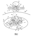
- the multimedia system 2 is supposed to serve a geographical coverage area 26 of small extent, between 500 000 km 2 and 1 500 000 km 2 .
- the coverage area 26 of the telecommunications service is France, and it lies between the meridians located at 5 ° west and 6 ° east, between latitudes 43 ° north and 51 ° north.
- the geostationary satellite 12 in geostationary orbit around the Earth 14 is placed on a first arc of the geostationary orbit near or contained in a second geostationary arc flying over the meridians of the extremity surrounding France.
- the geostationary satellite 12 is located on a median meridian crossing the center of France.
- the satellite 12 is located in a southern geographical direction 30 represented by the end arrow towards the rear of the plane of the Figure 1 .
- a north direction 32, opposite the south direction 30, is represented by a circumferential arrow on the surface of the Earth 14.
- the satellite 12 is viewed at an elevation angle designated El and shown in FIG. figure 2 as being a mean angle between the tangent in a longitudinal direction 34 at any point 36 of the cover 26 and the vector ray 38 connecting the point 36 of the cover 26 and the satellite 12.
- the satellite 12 comprises a stabilized geostationary platform 40, two solar panels 42, 44 and a multimedia telecommunication payload 46.
- the payload 46 is able to ensure the retransmission of multimedia services from the access stations 18, 19, 20, 21 to the multimedia terminals 6, 8, 10.
- the payload 46 is able to receive multimedia signals transmitted on an upstream channel 48 in a first band Ka by the access stations 18, 19, 20, 21.
- the payload 46 is capable of transmitting the multimedia signals received to the terminals 6, 8, 10 in a downlink channel 50 operating in a second band Ka, distinct from the first band Ka.
- the payload 46 is here transparent by limiting itself to the amplification and frequency translation of the multimedia signals.
- the payload 46 comprises a multimedia reception satellite antenna 52, a multimedia broadcast satellite antenna 54, and a multimedia mission repeater 56 connected between the multimedia reception satellite antenna 52 and the multimedia broadcast satellite antenna 54 by electrical connections 58 and 60.
- the multimedia repeater 56 comprises a power supply 61 of the payload 46 capable of conditioning the electrical energy supplied by the solar panels 42, 44 for the electrical elements constituting the payload 46.
- the multimedia broadcast satellite antenna 54 is a multibeam reflector antenna.
- It comprises a single reflector 62 having a focal plane 63 remote by a focal length F and a source block 64 comprising a plurality of elementary sources 66 of predetermined number Ns.
- the single reflector 62 is able to intercept part of the electromagnetic energy emitted by the source block 64 and to reflect the electromagnetic energy towards the coverage area 26 in descending multibeams.
- the reflector 62 is unique and has an apparent diameter D of 5 meters so as to form beams of angular size between 0.10 ° and 0.22 °.
- the opening angle of a beam generated by a radiating aperture having an apparent diameter is proportional to the wavelength of the radiation and inversely proportional to the apparent diameter.
- the radiating opening is the reflector 62.
- the elementary radioelectric sources 66 are arranged in the focal plane 63 and are able to illuminate the single reflector 62 by electromagnetic radiation in a Ka or Ku frequency band.
- the source block 64 is of the single-source per beam (SFB) type, each source being able to generate a different single beam and the diameter of each elementary source being equal to the image diameter in the focal plane of the beam. associated beam.
- SFB single-source per beam
- a beam of electromagnetic energy is called “primary” when it is established between an elementary source 66 of the source block 64 and the reflector 62, and the beam is called “secondary” when it is established between the reflector 62 and an elementary zone of the cover 26, regardless of the direction of propagation of the energy in the beam, that is to say of the transmission or reception mode of the antenna 46.
- the arrangement of the reflector 62 with respect to the platform 40, the orbital position and the stabilized attitude of the platform 40, the configuration of the antenna are chosen so that the antenna 54 generates secondary secondary beams covering by their footprint the Geographic coverage area 26 corresponding to France.
- the plurality 64 of the elementary radioelectric sources 66 forming the source block is configured to illuminate the reflector 62 by electromagnetic radiation according to a primary multibeam ensemble of primary adjacent beams, not shown in FIG. Figure 1 , divided into at least one connected set of adjacent primary beams, any two adjacent primary beams being separated by a first angular separation.
- the reflector 62 is configured to intercept a portion of the electromagnetic energy emitted by the source block 64 and to reflect it according to a secondary multibeam set of secondary secondary reflected beams 68 distributed in at least one connected set of adjacent secondary beams, two secondary beams. any adjacent ones being separated by a second angular separation.
- the source block 64 is sized and arranged so that the first angular separation is substantially equal to the second angular separation.
- the relative variation between the first angular separation and the second angular separation is less than 25%.
- B ⁇ D ⁇ F in which ⁇ s 2 denotes the second angular separation, ⁇ s 1 , denotes the first angular separation, and BDF is a coefficient referred to as the deflection factor of beam (in English Beam Deviation Factor) less than 1 and depends on the F / D ratio and the apodization of the elementary source.
- the coefficient BDF is between 0.7 and 1.
- the overflow energy losses associated with each source 66 are between 3 and 10 dB, preferably between 3 and 7.5 dB.
- Each source 66 is distinguished using an integer index k, with k varying between 1 and Ns, and denoted S (k).
- Each source S (k) is capable of receiving a distinct set of multimedia signals in a transmission sub-band B (i) taken from a set of distinct Nb subbands and without a cover band, the set of sub-bands. bands (B (i)) constituting a partition of the transmission band of the going way down, that is to say a partition of the second band.
- Each source S (k) is able to illuminate the reflector so as to reroute the signals in the downlink way 50 over a different associated elementary area S (k) of the coverage area 26.
- the optimal use of the frequency spectrum allocated on the downlink channel 68 in terms of capacity is obtained by the reuse of frequencies through the multibeam antenna 54.
- the multibeam antenna 54 with a single reflector 62 and with a source block of the "mono-source beam” type or SFB, as described above, allows the reuse of frequencies.
- the frequency band allocated for the multimedia service or second band is partitioned and a reuse of 1 / Nb is defined, in which Nb denotes a number of different colors, by associating a color with a subset of elementary zones (also called English "spot"), disjointed and distant from each other so as to have sufficient insulation.
- Nb denotes a number of different colors
- To each different color is assigned an integer index i, with i varying from 1 to Nb, and a subset of elementary zones A (i) or beams F (i). Reuse allows to spatially separate two beams using the same carrier frequency or subband.
- a distribution or distribution of the Nb colors on the elementary zones or the descending beams is chosen among the possible distributions of Nb colors on all the beams and consequently on all of their footprints, ie the basic zones of coverage.
- the "optimal" distribution of the Nb colors is optimal in terms of the frequency of reuse when the frequency of reuse of each color is substantially the same, that is to say equal to 1 / Nb, the edge effects being negligible when the number elementary areas is high.
- An "optimal" distribution of Nb colors is optimal in terms of C / I when the C / I on the cover 26 is maximal over all the possible distributions of Nb colors on all the beams.
- the use of the multibeam antenna 54 with a single large reflector 62 having a diameter greater than 4 meters using the single-beam source concept (English SFB for Single Feed per Beam) is advantageous.
- the multibeam antenna 54 allows for a fixed frequency reuse factor and an optimal scheme of reuse to increase the capacity of the system.
- the proposed telecommunication antenna is certainly suboptimal from an antenna subsystem point of view if it is considered in isolation. Indeed the spacing between the spots of the cover requires the use of sources of small diameters. They are thus not very directive and induce large losses in terms of spill-over, between 5 and 6 dB.
- B (total) is the total available band expressed in Hz
- B (allocated) is the frequency band allocated according to the regulatory provisions for the second band
- ⁇ is the frequency reuse factor
- ⁇ is the expressed spectral efficiency in bits / s / Hz.
- the spectral efficiency ⁇ is a function of the frequency density of EIRP (transmitted Isotropic Radiated Power) expressed in W / MHz, of the C / I, of the merit factor of the terminal and therefore of the C / N ratio, where N denotes the noise of observed thermal origin, and the waveform envisaged.
- the total available band increases with the number of beams on the cover.
- the spectral efficiency decreases with the number of beams because of a lower C / I on all the beams and thus with the degradation of C / N + I.
- the multibeam antenna 54 allows a gain in capacity in terms of increasing the number of beams despite spill over losses.
- the two multimedia terminals 6, 8 are located in the elementary zone 210.
- the third terminal 10 is located in the elementary zone 234, here assumed by way of example assigned the same color, that is to say operating in the same frequency sub-band of the second band.
- the C / I observed by the third terminal 10 comprises a component generated by the signals of the terminals 6 and 8, and received due to the lack of insulation of the beam 68 covering the elementary zone 210 with the beam covering the elementary zone 234 .
- Each terminal has a G / T factor equal to 16.4 dB / ° K, an antenna gain equal to 40 dB, which corresponds to an antenna diameter of about 65 cm.
- Each terminal 6, 8, 10 respectively comprises a flow matching device 250, 252, 254 as a function of the C / I conditions observed.
- Each rate adaptation device is capable of implementing a rate adaptation mode typically the "ACM" mode of the DVB-S2 described in the corresponding standard of the ETSI (European Telecommunication Standard Institute).
- a modulation can be chosen according to the C / I + N observed among the Quadrature Phase Shift Keing (QPSK) modulation, the 8-Phase Shift Keing (8-PSK) modulation, the 16-APSK modulation. 16-Amplitude & Phase Shift Keing) and 32-APSK (32-Amplitude & Phase Shift Keing) modulation.
- the coding may vary between the 1/4 and 9/10 rates offered by the LDPC code used in the DVB-S2 standard.
- the adaptive coding rate associated with the QPSK modulation can vary between 3/4 and 8/9.
- the adaptive coding rate associated with the 8-PSK modulation can vary between 3/5 and 3/4.
- the rate matching devices 250, 252, 254 allow to use modulation / coding combinations with a spectral efficiency to maximize the capacity of the system.
- the multimedia telecommunication system of the invention operates with low spectral efficiency values.
- the capacity of the system then obtained is 42% better than the capacity of the typical case in which the minimum C / I on the overall coverage 26 is equal to 15 dB.
- the Adaptive Coding and Modulation (ACM) mode defined in the DVB-S2 standard requires increases in useful signal power C and / or decreases in the received noise component N + I to go from one configuration to another. modulation and coding to another when the operating point of the system corresponds to a zone of low C / N + I values. In other words, small variations in C / N + I can bring a greater gain in spectral efficiency when the system operates in a zone of low C / N + I values. Thus, it is possible to generate particularly fine beams as proposed with the antenna of the invention.
- ACM Adaptive Coding and Modulation
- the number Nb of sub-bands is equal to 4 and the distribution of the four colors associated with the four frequency sub-bands B (i) is an "optimal" distribution or distribution of four colors in terms of frequency of reuse and C / I minimal.
- the distribution of the "four colors” as represented is the “optimal” distribution among the possible distributions of four colors on all beams and therefore all of their footprints on the ground, ie the elementary areas of coverage.
- the "optimal" distribution of four colors is optimal in terms of frequency of reuse when the frequency of reuse of each color is substantially the same, that is to say equal to a quarter, edge effects being negligible when the number elementary areas is large enough.
- a four-color distribution is said to be "optimal" in terms of C / I when the minimum C / I value over the entire coverage observed for this distribution is a maximum value over all possible four-color distributions. This corresponds to a maximum angular distance between any two beams having the same color, that is to say using the same sub-band.
- the spots or footprints of the beams are grouped into elementary clusters of four adjacent spots of different colors following the same geometric pattern or spatial arrangement of the four colors.
- the first cluster 302 comprises the four elementary coverage areas 210, 212, 214, 216 operating respectively on the forward downlink 50 in the sub-bands B (4), B (3), B (3), B (1) to which are assigned the colors designated respectively by the letters D, C, B, A.
- the second cluster 304 comprises the four elementary coverage areas 218, 220, 222, 224 operating respectively on the forward downlink 50 in the sub-bands B (4), B (3), B (2), B (1) to which are assigned the colors designated respectively by the letters D, C, B, A.
- the third cluster 306 comprises the four elementary coverage areas 226, 228, 230, 232 operating respectively on the forward downlink 50 in the sub-bands B (4), B (3), B (2) B (1) to which are assigned the colors designated respectively by the letters D, C, B, A.
- the fourth cluster 308 comprises the four elementary coverage areas 234, 236, 238, 240 operating respectively on the forward downlink 50 in the sub-bands B (4), B (3), B (2) B (1) to which are assigned the colors designated respectively by the letters D, C, B, A.
- Each elementary coverage area is the footprint of a different image beam, generated only by a single elemental source different from the source-set.
- the size of the sources is such that all the beams are generated by all the sources located in the same focal plane and that the overflow energy losses are minimal for the set of sources. This corresponds to placing the source centers so as to generate the central rays of each beam of the cover and to choose the rays of the largest possible sources until they come in contact.
- the source sizes corresponding to the single reflector have been reduced compared to the source sizes corresponding to several reflectors, and the corresponding overflow energy losses have increased.
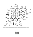
- the multibeam antenna 54 is shown in greater detail so as to highlight the correspondence between the network 64 of sources 66 and the distribution of the beams on the service coverage 26 according to the elementary zones and the four-color coloring described in FIG. the Figure 3 .
- the source block 64 or focal network comprises at least one connected set of elementary sources.
- the elementary sources 66 are here horn type antennas.
- the arrangement of the radio sources in the focal plane is that of a configuration corresponding to the optimized distribution of the subbands for the four colors designated by the letters A, B, C and D.
- the sources 502, 504, 506, 508 are arranged side by side in a first row 542.
- the sources 510, 512, 514, 516 are arranged side by side along a second row 544.
- the sources 518, 520 522, 524 are arranged next to a third row 544.
- the sources 526, 528, 530, 532 are arranged side by side in a fourth row.
- the four rows 542, 544, 546, 548 are arranged side by side so that the sources 502, 510, 518, 526 form a first column 552 of direction perpendicular to the common direction of the four rows 542, 544, 546, 548.
- the sources 504, 512, 520, 528 form a second column 554
- the sources 506, 514, 522, 530 form a third column 556
- the sources 508, 516, 524, 532 form a fourth column 558.
- Color A is assigned to sources 502, 506, 518, 522.
- Color B is assigned to sources 504, 508, 520, 524.
- Color C is assigned to sources 510, 514, 526, 530.
- Color D is assigned at sources 512, 516, 528, 532.
- the sources 502, 504, 510, 512 correspond respectively to the elementary zones 240, 238, 236, 234 of the fourth cluster 308.
- the sources 506, 508, 514, 516 correspond to the elementary zones of the third cluster 306.
- the sources 518, 520, 526, 528 correspond to the elementary zones of the second cluster 306.
- the sources 506, 508, 514, 516 correspond to the elementary zones of the first cluster 306.
- the reflector 62 is a reflector with rigid hull foldable or deployable mesh technology (referred to in English "Mesh technology"), adapted to be accommodated on a platform in a transport position in which the assembly formed by the platform and the reflector is contained in the cap of a launcher.
- the single reflector 62 is able to be deployed from the carrying position on a platform to a deployment position represented on the Figures 4 and 6 .
- the reflector 62 is a portion of a paraboloid P offset from the source block 64 so as to avoid the masking by the source block 64 of the secondary beams, here the beams going down to the coverage area 26.
- the paraboloid portion is for example an elliptically shaped cut of the paraboloid.
- the center of the dish and the focal point of the dish are designated respectively by C P , and F1, while the cutting center is designated by C D -Next Figure 6 , the clearance height of the source block 64 with respect to the reflector 62 is designated H.
- the apparent diameter of the reflector 62, denoted by D, is equal to the size of the projected surface obtained by orthogonal projection of the surface of the reflector in the plane containing C P and having as normal the axis passing through C P and the focal point F1.
- the cutting point C D is located at a height equal to H + D / 2 with respect to the axis passing through the center C P and the focal point F1.
- the focal length designated by the letter F is equal to the distance between the center of symmetry C P of the paraboloid portion and the focal point F1 of the paraboloid.
- the equivalent focal length, denoted by Feq, is equal to the distance between the cutting center C D of the paraboloid portion P and the focal point F1 of the paraboloid P.
- the angle of angular separation between two adjacent primary beams is substantially equal to the angular separation angle between two adjacent secondary beams, shown in FIG. Figure 6 by ⁇ s2 for the first pair of corresponding elementary areas 240 and 236 and the second pair of corresponding elementary areas 236 and 224.
- ⁇ s1 and ⁇ s2 will be designated identically by ⁇ s.
- the reflector can be considered as governed by the laws of geometrical optics and then the size or size of the sources is governed by the following relation: D s ⁇ o ⁇ u ⁇ r ⁇ vs ⁇ e ⁇ F ⁇ e ⁇ q * tan ⁇ ⁇ s ⁇ 2 / B ⁇ D ⁇ F wherein D source means the opening diameter of the circular horn forming an elementary source of the related set of elementary sources.
- the reflector is a paraboloid portion centered on its paraboloidal center of symmetry C P.
- the focal plane of the reflector in which the radioelectric sources 66 are arranged is orthogonal to the axis passing through the center of symmetry C P of the paraboloid and the F1 focal point of the paraboloid.
- Any elementary source 66 of the source block 64 has an opening size denoted T source , which verifies the relation T s ⁇ o ⁇ u ⁇ r ⁇ vs ⁇ e ⁇ F * tan ⁇ ⁇ s ⁇ 2 / B ⁇ D ⁇ F .
- the elementary sources are openings having a closed contour of any shape having a size denoted T source , and corresponding to an equivalent diameter.
- the focal length F separating the focal plane 63 and the cutting center 402 (C D ) of the reflector 62, here is between 4 meters and 7 meters.
- coefficient of "spill-over” reflects the degree of adequacy of the diagram of the source at the angle under which it sees the reflector and this term is equal to the ratio of the energy effectively intercepted to the total energy radiated by this source.
- the reflector 62 captures only about a quarter of the energy from the sources 66 and the coefficient of spill over is equal to about 0.25, which gives spill losses of between 5 and 6 dB.
- such an antenna configuration makes it possible to increase the capacity of a multimedia system covering a geographical area the size of France.
- Beam Forming Network Beam Forming Network
- This BFN beamforming network allows to interleave the sources and to illuminate the reflector optimally.
- a "low level" BFN is arranged before the power amplification section of the payload.
- the number of amplification devices is equal to or even a multiple of the number of sources of the focal network which is itself greater than the number of beams of the cover.
- the sources have a diameter identical to the image diameter of the beams in the focal plane.
- a "high level" BFN is arranged after the amplification section of the repeater channels each corresponding to a beam.
- the number of amplification devices is equal to the number of beams of the cover.
- elementary sources are twice as small as the image diameter of the beam in the focal plane.
- a disadvantage of this solution is the existence of a minimum diameter of the sources due to the limitation of the focal length of the reflector. With such a solution, the spill over coefficient is of value less than the spill over coefficient of the configuration of the invention namely a single elementary source per beam (SFB solution for Single Feeder per Beam), and this leads to revise the number of beams.
- the spill-over coefficient being between 5 and 6 dB and the C / I being between +9 dB and +23 dB
- the solution of the invention namely a single reflector antenna and an SFB-type source assembly to increase the number of beams and the capacity while respecting the carriage constraints of the antenna on conventional launchers and consumption limitations on existing platforms.
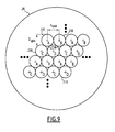
- a source block comprises a single connected set of adjacent radioelectric sources formed by horns.
- the arrangement of the radio sources in the focal plane is that of a configuration corresponding to the optimized distribution of the subbands for three colors designated by the letters A, B and C.
- the sources 602, 604, 606, respectively the sources 608, 610, 612 and the sources 614, 616, 618 are arranged in a first row, respectively a second row and a third row.
- the sources of two consecutive rows are generally shifted by a length equal to a radius of a source, so that for example the sources 602, 604, 610 form an equilateral triangle.
- This configuration using a mesh or ternary pattern of color distribution in the shape of an equilateral triangle corresponds to an optimal frequency reuse scheme for which the frequency of use of the three colors and the minimal C / I are the largest. the angular coverage generated by all the beams from the sources.
- the payload repeater 56 includes an input 602 of the uplink upstream receive antenna 52 through its source 603, a first frequency demultiplexer 604 of signals from two different satellite access stations connected. at the input 602 of the receiving antenna.
- the repeater 56 also comprises, for each set of signals received and transmitted by the same access station, a second device for frequency demultiplexing 606 of the signals intended for different downstream beams, here four in number and corresponding to one and the same cluster of elementary zones on four different elementary power output channels.
- the signals intended for the same downstream beam are emitted in the same uplink rising-frequency sub-band, and that the rising-frequency sub-bands associated with the descending beams of the same clusters of elementary zones are juxtaposed to form a frequency band associated with a cluster.
- Each elementary output power transmission channel 608, 610, 612, 614 includes an own transposition device 616, 618, 620, 622 followed by an associated output power amplification means 624, 626, 628, 630, capable of delivering the output power to the source of the corresponding beam.
- the sources connected to the output terminals of the basic transmission power output channels are the sources of the figure 5 designated 502, 504, 510, 512.
- the other elementary sources of the source assembly like sources 502, 504, 510, 512, are connected to a single and different path of elementary power transmission output.
- the repeater is configured to supply each source of the antenna 54 on a single path of clean routing of the downstream traffic and intended for the corresponding elementary zone.
- Each output power amplification means 624, 626, 628, 630 is here a Progressive Wave Tube Amplifier (ATOP) operating in Ka-band.
- ATOP Progressive Wave Tube Amplifier
- Each ATOP 624, 626, 628, 630 is able to amplify a sub-band or color among the four colors of the second band allocated, each sub-band having a bandwidth of 1450 MHz and able to deliver an output power of 170 W.
- Each ATOP is used here on an operating point taken at 3 dB of recoil, the output losses between the output of the ATOP and the input of the source being equal to 2.6 dB.
- the transposition devices are configured to provide each elementary output power transmission channel with radio signals in a frequency sub-band B (i) from a predetermined number N of frequency sub-bands forming a band. allocated frequency.
- the frequency transposition means are able to distribute the frequency sub-bands to the output transmission paths and to all the elementary radioelectric sources so that the diagram the ground formed by the colors associated with the different beams generated by the antenna is an optimized frequency reuse N-color diagram, that is to say a diagram for which the angular distance between two beams using the same color is the larger on all possible diagrams.
- the global coverage is divided into 62 elementary zones for which is obtained the largest total capacity on the downward one way.
- This maximum total capacity equal to approximately 100 Gbits / s, is obtained for a tiling of the coverage area into 62 elementary zones, subject to using a frequency reuse factor equal to 4, an electric power available on board the satellite for the payload equal to 12 kW, a minimum permissible C / I equal to 9 dB.
- the telecommunication antenna and the payload are configured to operate in the C band.
- the antenna functions in reception mode.
- the plurality of elementary radioelectric sources 66 is configured to be illuminated by the reflector 62 by electromagnetic radiation in a frequency band according to a primary multibeam ensemble of primary adjacent beams distributed in at least one connected set of adjacent primary beams. any two adjacent primary beams being separated by a first angular separation.
- the reflector 62 is configured to intercept a portion of the electromagnetic energy transmitted from the geographical zone 26, according to a secondary multibeam set of secondary adjacent reflected beams distributed in at least one connected set of adjacent secondary beams, two adjacent adjacent sub-beams being separated by a second angular separation.
- the first angular separation and the second angular separation are substantially equal.
- the telecommunication antenna is configured to operate in transmission and reception with the same reflector.
- the reflector is a shaped reflector and the elementary sources forming the source block are arranged in a medium plane with deviations in distances around this average plane, which is a function of the conformation of the reflector.
- the telecommunication system comprises two satellites configured in a "flying formation".
- the reflector is mounted on a first satellite while the source block and the payload are mounted on a second satellite.
Abstract
Description
La présente invention concerne une antenne de télécommunication destinée à être embarquée à bord d'un satellite de télécommunication, une charge utile d'un satellite de télécommunication comprenant l'antenne, et un système de télécommunication utilisant la charge utile et donc l'antenne de télécommunication.The present invention relates to a telecommunication antenna intended to be on board a telecommunication satellite, a payload of a telecommunication satellite comprising the antenna, and a telecommunication system using the payload and therefore the antenna of telecommunication.
De manière générale et jusqu'à présent dans le cas des télécommunications spatiales utilisant les satellites géostationnaires pour la transmission de services multimédia en bande Ka, on cherche à élargir la couverture fournie par la ou les antennes de télécommunication embarquées à bord du satellite et à augmenter la capacité de transmission tout en assurant une performance en C/I (rapport du signal utile sur signaux interférents) élevée.In general, and so far in the case of space telecommunications using geostationary satellites for the transmission of multimedia services in Ka-band, it is sought to extend the coverage provided by the on-board telecommunication antenna or antennas and to increase the transmission capacity while ensuring a performance in C / I (useful signal ratio on interfering signals) high.
Pour obtenir la performance de niveau système attendue, il faut disposer d'antennes de télécommunication qui assurent une isolation spatiale suffisante entre faisceaux ou leurs empreintes au sol dénommées par la suite zones élémentaires ou spots, de sorte à permettre des réutilisations programmées de manière fixe ou dynamique de tout ou partie des ressources en fréquences allouées au système (réutilisation des fréquences).To obtain the expected system-level performance, it is necessary to have telecommunication antennas which provide sufficient spatial isolation between beams or their footprints, henceforth referred to as elementary zones or spots, so as to allow fixed or programmed reuses. dynamic of all or part of the frequency resources allocated to the system (reuse of frequencies).
Compte tenu du grand nombre de spots à réaliser, un nombre élevé d'antennes directives est à implanter sur une même plateforme de satellite et il est également nécessaire de disposer de structures à grande focale pour réaliser des performances d'isolation élevée entre faisceaux associées à une stabilité de pointage sévère.Given the large number of spots to be made, a large number of directional antennas is to be implemented on the same satellite platform and it is also necessary to have structures with large focal length to achieve high insulation performance between beams associated with severe pointing stability.
De nos jours, les missions multimédias en bande Ka utilisent des solutions d'antenne à multiples réflecteurs. En effet l'utilisation de plusieurs réflecteurs permet d'utiliser des sources suffisamment grandes pour éclairer de manière optimale les réflecteurs et former ainsi des faisceaux fins avec une directivité élevée maximale (rendement d'antenne élevé).Today, Ka-band multimedia missions use multi-reflector antenna solutions. Indeed the use of multiple reflectors allows to use sources large enough to illuminate the reflectors optimally and thus form fine beams with a high maximum directivity (high antenna output).
Ainsi, le satellite le plus récent en Europe utilisant ce type d'antenne est le satellite dénommé Ka-sat de l'opérateur Eutelsat. Il fournit une couverture européenne à l'aide d'environ 80 faisceaux de 0,45° d'ouverture angulaire générés par quatre réflecteurs de 2,6 mètres de diamètre. Chacun de ces réflecteurs fonctionne sur une voie d'émission aller descendante et sur une voie de réception retour montante. Ce système de communication est prévu pour fournir une capacité totale d'environ 70 Gbits/s, le rapport en C/I minimal sur la couverture étant de l'ordre de 14 dB.Thus, the most recent satellite in Europe using this type of antenna is the satellite called Ka-sat of the operator Eutelsat. It provides European coverage using about 80 beams of 0.45 ° angular aperture generated by four reflectors 2.6 meters in diameter. Each of these reflectors operates on a go-down transmission path and an uplink receive path. This communication system is intended to provide a total capacity of approximately 70 Gbps, the minimum C / I coverage ratio being in the order of 14 dB.
Il est à remarquer que le satellite Ka-sat aurait pu utiliser un unique réflecteur de 2,6 mètres de diamètre. Dans ce cas il aurait été nécessaire de réaliser des sources d'éclairement plus petites, ce qui aurait dégradé le rendement de l'antenne notamment par l'augmentation des pertes d'énergie par débordement (dénommées en anglais « spill-over »), typiquement de 4 à 6 dB. La performance en C/I restant de l'ordre de 12 dB la perte d'efficacité de l'antenne aurait entraîné une dégradation de la Puissance Rayonnée Isotrope Emise (PIRE), ce qui se serait traduit par une perte de capacité du système de télécommunication notable et non désirée.It should be noted that the satellite Ka-sat could have used a single reflector of 2.6 meters in diameter. In this case it would have been necessary to make sources smaller illumination, which would have degraded the performance of the antenna including the increase in energy losses overflow (called spill-over), typically 4 to 6 dB. The remaining C / I performance of about 12 dB loss of antenna efficiency would have resulted in a degradation of Isotropic Emitted Radiated Power (EIRP), which would have resulted in a loss of capacity of the transmission system. noticeable and unwanted telecommunications.
De nos jours, plusieurs missions sont distinguées allant de la couverture d'une région de grande taille par exemple l'Europe jusqu'à des couvertures concernant un ou un nombre limité de plusieurs pays européens.Today, several missions are distinguished, ranging from coverage of a large region, for example Europe, to coverage of one or a limited number of European countries.
L'étude de couvertures concernant un à trois pays est actuellement l'objet de nombreuses recherches et développements. Par exemple, la fourniture d'un satellite de télécommunication multimédia à capacité élevée et ayant pour zone de couverture un pays de la taille de la France est envisagée.Coverage studies for one to three countries are currently the subject of much research and development. For example, the provision of a high-capacity multimedia telecommunications satellite with a coverage area of the size of France is envisaged.
Dans ces systèmes en cours d'étude et de développement, l'augmentation de la capacité est toujours recherchée par l'utilisation d'une bande passante allouée plus large lorsque la règlementation le permet ou encore par la réutilisation du spectre dans des zones réduites à l'aide de pinceaux très fins.In these systems under study and development, the increase in capacity is always sought by the use of a wider allocated bandwidth when the regulation allows it or by the reuse of the spectrum in zones reduced to using very fine brushes.
Franchir ce fossé en termes de capacité nécessite alors l'utilisation de faisceaux plus fins.Bridging this gap in terms of capacity then requires the use of finer beams.
Or les capacités d'emport des plateformes et des lanceurs actuels ne permettent pas d'envisager de solutions à multiples réflecteurs de diamètre supérieur à 3 mètres ou 3,5 mètres.However, the carrying capacities of the current platforms and launchers do not make it possible to envisage solutions with multiple reflectors of diameter greater than 3 meters or 3.5 meters.
Ainsi l'utilisation de quatre réflecteurs de 3,2 mètres de diamètre correspond actuellement à une configuration limite d'emport sur un satellite pour rentrer dans une coiffe d'un lanceur.Thus the use of four reflectors of 3.2 meters in diameter currently corresponds to a limit configuration of carriage on a satellite to enter a cap of a launcher.
Pour cette configuration d'antennes à quatre réflecteurs et en optimisant au mieux les paramètres déterminants de poids fort du système, on obtient une capacité d'environ 65 Gbits/s avec 36 faisceaux sur la France.For this configuration of antennas with four reflectors and optimizing the most important determining parameters of the system, we obtain a capacity of about 65 Gbits / s with 36 beams on France.
Dans cette configuration limite, les sources sont optimisées pour les quatre réflecteurs et les pertes par débordement s'élèvent à environ 2 dB pour un C/I minimal de l'ordre de 9 dB.In this limit configuration, the sources are optimized for the four reflectors and the overflow losses are around 2 dB for a minimum C / I of the order of 9 dB.
En outre, lorsque le nombre de faisceaux augmente, les C/I observés deviennent très faibles et, en dépit de la réutilisation des fréquences, la capacité diminue.In addition, as the number of beams increases, the C / I observed becomes very low and, despite the reuse of frequencies, the capacity decreases.
Le problème technique est d'augmenter la capacité de transmission du satellite dans des conditions de fonctionnement du satellite identiques à celles présentées pour la configuration limite en termes de puissance consommée par la charge utile multimédia du satellite, de bande de fréquences allouée à la voie descendante, de caractéristiques des terminaux et de contraintes d'emport sur un satellite destiné à rentrer dans une coiffe d'un lanceur.The technical problem is to increase the transmission capacity of the satellite under satellite operating conditions identical to those presented for the limit configuration in terms of the power consumed by the multimedia payload of the satellite. satellite, frequency band allocated to the downlink, characteristics of the terminals and carriage constraints on a satellite intended to fit into a launcher cap.
A cette fin, l'invention a pour objet une antenne de télécommunication multifaisceaux destinée à équiper une charge utile de télécommunication à débit élevé pour couvrir en émission et/ou en réception une zone géographique depuis une orbite géostationnaire, apte à être montée mécaniquement sur une ou deux plateformes de satellite et à être couplée électro-magnétiquement à un répéteur, comprenant :
- au moins un réflecteur radioélectrique, et
- un bloc source associé, formé d'une pluralité de sources radioélectriques élémentaires disposées dans un plan,
- la pluralité des sources radioélectriques élémentaires étant configurée pour illuminer le réflecteur par un rayonnement électromagnétique dans une bande de fréquences et/ou pour être illuminé par un rayonnement électromagnétique dans une bande de fréquences réfléchi par le réflecteur selon un ensemble multifaisceaux primaire de faisceaux adjacents primaires répartis en au moins un ensemble connexe de faisceaux primaires adjacents, deux faisceaux primaires quelconques adjacents étant séparés par une première séparation angulaire θS1,,
- le réflecteur étant configuré pour réfléchir une partie de l'énergie électromagnétique émise par le bloc source et/ou pour intercepter une partie de l'énergie électromagnétique émise depuis la zone géographique, selon un ensemble multifaisceaux secondaire de faisceaux réfléchis adjacents secondaires répartis en au moins un ensemble connexe de faisceaux secondaires adjacents, deux faisceaux secondaires quelconques adjacents étant séparés par une deuxième séparation angulaire θS2,
- caractérisée en ce que
- le réflecteur est unique, et
- le bloc source est dimensionné et agencé de sorte que chaque source est apte à générer et/ou recevoir un faisceau unique différent et que la première séparation angulaire θS1 est sensiblement égale à la deuxième séparation angulaire θS2, et
- les pertes d'énergie par débordement associées à chaque source sont comprises entre 3 et 10 dB, de préférence comprises entre 3 et 7,5 dB.
- at least one radio reflector, and
- an associated source block formed of a plurality of elementary radioelectric sources arranged in a plane,
- the plurality of elementary radioelectric sources being configured to illuminate the reflector with electromagnetic radiation in a frequency band and / or to be illuminated by electromagnetic radiation in a frequency band reflected by the reflector according to a primary multibeam set of distributed primary adjacent beams in at least one connected set of adjacent primary beams, any two adjacent primary beams being separated by a first angular separation θ S1 ,,
- the reflector being configured to reflect a portion of the electromagnetic energy emitted by the source block and / or to intercept a portion of the electromagnetic energy emitted from the geographical area, according to a secondary multibeam ensemble of adjacent secondary reflected beams distributed in at least a connected set of adjacent secondary beams, any two adjacent secondary beams being separated by a second angular separation θ S2 ,
- characterized in that
- the reflector is unique, and
- the source block is dimensioned and arranged so that each source is able to generate and / or receive a different single beam and that the first angular separation θ S1 is substantially equal to the second angular separation θ S2 , and
- the overflow energy losses associated with each source are between 3 and 10 dB, preferably between 3 and 7.5 dB.
Suivant des modes particuliers de réalisation, l'antenne de télécommunication comporte l'une ou plusieurs des caractéristiques suivantes :
- le réflecteur est un réflecteur non conformé, et
- le plan dans lequel sont disposées les sources radioélectriques est un plan focal du réflecteur ;
- le réflecteur est une portion de paraboloïde centrée sur son centre de symétrie de paraboloïde CP,
- le plan focal du réflecteur dans lequel sont disposées les sources radioélectriques est orthogonal à l'axe passant par le centre de symétrie CP du paraboloïde et le point focal F1 du paraboloïde,
- une source quelconque du bloc source a une taille d'ouverture notée Tsource, qui vérifie la relation
- Tsource ≤ F ∗ tan(θ s2 ∗ (1 + ε))
- dans laquelle
- F désigne la distance focale égale à la distance entre le centre CP de symétrie de la portion de paraboloïde et le point focal F1 du paraboloïde,
- Θs2 désigne la séparation angulaire de deux faisceaux adjacents secondaires, et
- ε est un coefficient numérique compris entre 0 et +0,35 ;
- le réflecteur est une portion d'un paraboloïde décalée par rapport au bloc source de façon à éviter le masquage des faisceaux secondaires par le bloc source, et
- une source quelconque du bloc source a une taille d'ouverture notée Tsource, qui vérifie la relation
- Tsource ≤ Feq ∗ tan(θ s2 ∗ (1 + ε))
- dans laquelle
- Feq désigne une distance focale équivalente égale à la distance entre un centre CD de découpe de la portion de paraboloïde et le point focal F1 du paraboloïde,
- Θs2 désigne la séparation angulaire de deux faisceaux adjacents secondaires, et
- ε est un coefficient numérique compris entre 0 et +0,35 ;
- le réflecteur est une portion d'un paraboloïde, et
- le bloc source comprend au moins un ensemble de sources radioélectriques adjacentes formées de cornets à ouverture circulaire, chaque cornet de l'ensemble ayant un diamètre Dsource incluant l'épaisseur métallique de la paroi du cornet, et
- le diamètre Dsource de l'ouverture vérifie la relation :
- Dsource = Feq ∗ tan(θs2 ∗ (1+ε)) lorsque le réflecteur est une portion d'un paraboloïde décalée par rapport au bloc source, et la relation
- Dsource = F ∗ tan(θ s2 ∗ (1+ε)) lorsque le réflecteur est une portion de paraboloïde centrée sur son centre de symétrie de paraboloïde CP,
- dans lesquelles
- F désigne la distance focale égale à la distance entre le centre CP de symétrie de la portion de paraboloïde et le point focal F1 du paraboloïde,
- Feq désigne une distance focale équivalente égale à la distance entre un centre CD de découpe de la portion de paraboloïde et le point focal F1 du paraboloïde,
- Θs2 désigne la séparation angulaire de deux faisceaux adjacents secondaires, et ε est un coefficient numérique compris entre 0 et +0,35 ;
- le bloc source et le réflecteur sont configurés pour fonctionner dans une bande de fréquence comprise dans l'ensemble des bandes C, Ku, Ka ;
- la disposition des sources radioélectriques dans le plan est celle d'une configuration correspondant à une distribution optimisée pour un nombre de couleurs égal à 3, 4, ou 7 ;
- la valeur minimale sur la couverture géographique du rapport C/I entre, d'une part l'énergie émise et/ou reçue par le réflecteur dans un faisceau secondaire quelconque, et d'autre part la somme des énergies émises et/ou reçues dans le même faisceau secondaire et émises et/ou reçues par le réflecteur depuis les autres faisceaux de même couleur que le faisceau secondaire, est inférieur à 15 dB, de préférence à 12 dB.
- the reflector is an unconformed reflector, and
- the plane in which the radioelectric sources are arranged is a focal plane of the reflector;
- the reflector is a paraboloid portion centered on its paraboloid center of symmetry C P ,
- the focal plane of the reflector in which the radioelectric sources are arranged is orthogonal to the axis passing through the center of symmetry C P of the paraboloid and the focal point F1 of the paraboloid,
- any source of the source block has an opening size denoted T source , which verifies the relation
- T source ≤ F * tan ( θ s 2 * (1 + ε ))
- in which
- F denotes the focal length equal to the distance between the center of symmetry C P of the paraboloid portion and the focal point F1 of the paraboloid,
- Θs2 denotes the angular separation of two adjacent adjacent beams, and
- ε is a numerical coefficient between 0 and +0.35;
- the reflector is a portion of a paraboloid offset from the source block so as to avoid the masking of the secondary beams by the source block, and
- any source of the source block has an opening size denoted T source , which verifies the relation
- T source ≤ Feq * tan ( θ s 2 * (1 + ε ))
- in which
- F eq denotes an equivalent focal length equal to the distance between a cutting center C D of the paraboloid portion and the focal point F1 of the paraboloid,
- Θs2 denotes the angular separation of two adjacent adjacent beams, and
- ε is a numerical coefficient between 0 and +0.35;
- the reflector is a portion of a dish, and
- the source block comprises at least one set of adjacent radioelectric sources formed of circular opening horns, each horn of the assembly having a source diameter D including the metal thickness of the wall of the horn, and
- the diameter D source of the opening satisfies the relation:
- D source = Feq * tan ( θ s2 * (1+ ε )) when the reflector is a portion of a paraboloid offset from the source block, and the relation
- D source = F * tan ( θ s 2 * (1+ ε )) when the reflector is a paraboloid portion centered on its paraboloid center of symmetry C P ,
- in which
- F denotes the focal length equal to the distance between the center of symmetry C P of the paraboloid portion and the focal point F1 of the paraboloid,
- F eq denotes an equivalent focal length equal to the distance between a cutting center C D of the paraboloid portion and the focal point F1 of the paraboloid,
- Θs2 denotes the angular separation of two adjacent adjacent beams, and ε is a numerical coefficient between 0 and +0.35;
- the source block and the reflector are configured to operate in a frequency band included in the set of C, Ku, Ka bands;
- the arrangement of the radio sources in the plane is that of a configuration corresponding to an optimized distribution for a number of colors equal to 3, 4, or 7;
- the minimum value over the geographical coverage of the C / I ratio between, on the one hand, the energy emitted and / or received by the reflector in any secondary beam, and, on the other hand, the sum of the energies emitted and / or received in the same secondary beam and emitted and / or received by the reflector from the other beams of the same color as the secondary beam, is less than 15 dB, preferably 12 dB.
L'invention a également pour objet une charge utile de télécommunication destinée à transmettre et/ou recevoir des données à débit élevé, comprenant une antenne d'émission et/ou de réception telle que définie ci-dessus et un répéteur, caractérisé en ce que
le répéteur comprend un ensemble de voies de transmission en émission et/ou en réception,
chaque voie de transmission comprenant
une borne de sortie et/ou d'entrée radioélectrique connectée à un source radioélectrique unique et différente du bloc source, et
étant configurée pour fournir des signaux radioélectriques dans une sous-bande de fréquence B(i) parmi un nombre prédéterminé Nb de sous-bandes de fréquences formant une bande de fréquence allouée, et en ce que
chaque sous-bande B(i) étant associée à une couleur, les voies de transmission sont aptes à distribuer en émission et/ou en réception les sous-bandes de fréquences à l'ensemble des sources radioélectriques élémentaires de sorte que le diagramme au sol formé par les couleurs associées aux différents faisceaux secondaires générés par l'antenne est un diagramme à Nb couleurs de réutilisation de fréquences optimisé, c'est-à-dire un diagramme pour lequel la distance angulaire entre deux faisceaux utilisant une même couleur est la plus grande sur l'ensemble des diagrammes possibles.The subject of the invention is also a telecommunication payload intended to transmit and / or receive data at a high bit rate, comprising a transmitting and / or receiving antenna as defined above and a repeater, characterized in that
the repeater comprises a set of transmission channels in transmission and / or in reception,
each transmission channel comprising
an output and / or radio input terminal connected to a single radio source and different from the source block, and
configured to provide radio signals in a sub-band of frequency B (i) out of a predetermined number Nb of frequency sub-bands forming an allocated frequency band, and in that
each sub-band B (i) being associated with a color, the transmission channels are capable of distributing the frequency sub-bands in transmission and / or reception to all the elementary radioelectric sources so that the ground diagram formed by the colors associated with the different secondary beams generated by the antenna is a diagram with Nb optimized frequency reuse colors, that is to say a diagram for which the angular distance between two beams using the same color is the most large on all possible diagrams.
L'invention a également pour objet un système de télécommunication par satellite comprenant :
- un satellite de télécommunication équipé d'une charge utile telle que définie ci-dessus,
- un ensemble de terminaux de télécommunication pouvant transmettre et/ou recevoir des signaux radioélectriques vers/depuis le satellite,
- une ou plusieurs stations d'accès satellitaire aptes à émettre et/ou recevoir des signaux radioélectriques aux/des terminaux au travers du satellite suivant une liaison montante aller et/ou retour , et
- chaque terminal est apte à déterminer le rapport C/I+N observé par son antenne respective et/ou par l'antenne satellite entre, d'une part l'énergie C reçue associée au signal radioélectrique utile du terminal et contenue dans le faisceau secondaire de couverture du terminal, et d'autre part, la somme I des énergies reçues dans le même faisceau secondaire mais émises depuis les autres faisceaux secondaires de même couleur que la source associée au faisceau secondaire de couverture du terminal et de l'énergie N du bruit thermique reçu,
- et comprend un dispositif d'adaptation de débit reçu ou transmis en fonction des conditions de C/I+N observées, le débit étant variable par la modification du nombre d'états d'une modulation et/ou le taux de codage et/ou le débit symbole.
- a telecommunication satellite equipped with a payload as defined above,
- a set of telecommunication terminals capable of transmitting and / or receiving radio signals to / from the satellite,
- one or more satellite access stations able to transmit and / or receive radio signals to / from the terminals through the satellite in a forward and / or return uplink, and
- each terminal is able to determine the ratio C / I + N observed by its respective antenna and / or by the satellite antenna between, on the one hand, the received energy C associated with the useful radio signal of the terminal and contained in the secondary beam of the terminal, and on the other hand, the sum I of the energies received in the same secondary beam but emitted from the other secondary beams of the same color as the source associated with the secondary beam of coverage of the terminal and the energy N of the terminal. received thermal noise,
- and comprises a rate matching device received or transmitted according to the conditions of C / I + N observed, the bit rate being variable by the modification of the number of states of a modulation and / or the coding rate and / or the symbol flow.
L'invention sera mieux comprise à la lecture de la description d'une unique forme de réalisation qui va suivre donnée uniquement à titre d'exemple et faite en se référant aux dessins sur lesquels :
- la
Figure 1 est une vue générale de l'architecture d'un système de télécommunication à satellite géostationnaire selon l'invention; - la
Figure 2 est une vue géométrique du satellite et de la couverture de service permettant de visualiser l'angle d'élévation du satellite vu d'un point quelconque de la couverture ; - la
Figure 3 est une vue partielle de la couverture de l'antenne de télécommunication du satellite desFigures 1 et 2 avec la répartition des fréquences associées aux faisceaux suivant une configuration à quatre couleurs ; - la
Figure 4 est un schéma du système de télécommunication permettant de visualiser le lien entre la répartition des sous-bandes sur les sources de l'antenne et la distribution des sous-bandes sur les faisceaux de la voie descendante allant du satellite aux terminaux; - la
Figure 5 est une vue du bloc source de l'antenne de laFigure 4 configuré suivant une répartition à quatre couleurs; - la
Figure 6 est une vue d'une coupe de l'antenne de laFigure 4 suivant l'axe VI-VI ; - la
Figure 7 est une variante à trois couleurs du bloc source de laFigure 5 ; - la
Figure 8 est une vue partielle du répéteur du satellite et de son couplage électrique au bloc source de l'antenne ; - la
Figure 9 est une vue partielle de la couverture de service obtenue avec le satellite de laFigure 2 équipé de l'antenne de télécommunication desFigures 4 et5 , et du bloc source à quatre couleurs de laFigure 5 ;
- the
Figure 1 is a general view of the architecture of a geostationary satellite telecommunications system according to the invention; - the
Figure 2 is a geometric view of the satellite and the service coverage for viewing the elevation angle of the satellite as viewed from any point in the coverage; - the
Figure 3 is a partial view of the coverage of the telecommunication antenna of the satellite ofFigures 1 and2 with the distribution of the frequencies associated with the beams in a four-color configuration; - the
Figure 4 is a schematic of the telecommunication system for visualizing the link between the distribution of the subbands on the antenna sources and the distribution of the subbands on the downlink beams from the satellite to the terminals; - the
Figure 5 is a view of the source block of the antenna of theFigure 4 configured in a four-color pattern; - the
Figure 6 is a view of a section of the antenna of theFigure 4 along the axis VI-VI; - the
Figure 7 is a three-color variant of the source block of theFigure 5 ; - the
Figure 8 is a partial view of the satellite repeater and its electrical coupling to the source block of the antenna; - the
Figure 9 is a partial view of the service coverage obtained with the satellite of theFigure 2 equipped with the telecommunications antenna of theFigures 4 and5 , and the four-color source block of theFigure 5 ;
Le système multimédia 2 est supposé desservir une zone géographique de couverture 26 de faible étendue, comprise entre 500 000 km2 et 1 500 000 km2.The
Typiquement cela correspond pour l'hémisphère nord à un, deux ou trois pays de la taille de la France chacun.Typically this corresponds for the northern hemisphere to one, two or three countries the size of France each.
Ici à titre d'exemple, la zone de couverture 26 du service de télécommunication est la France, et elle est comprise entre les méridiens situés à 5° ouest et 6° est, entre les latitudes 43° nord et 51 °nord.Here as an example, the
Le satellite géostationnaire 12 en orbite géostationnaire autour de la Terre 14 est placé sur un premier arc de l'orbite géostationnaire proche ou contenu dans un deuxième arc géostationnaire survolant les méridiens d'extrémité entourant la France. Ici, sur la
Par rapport à la zone de couverture 26, le satellite 12 est situé suivant une direction sud géographique 30 représentée par la flèche de bout allant vers l'arrière du plan de la
Depuis la zone de couverture 26, le satellite 12 est vu suivant un angle d'élévation désigné par El et représenté sur la
Suivant la
La charge utile 46 est apte à assurer la retransmission de services multimédia depuis les stations d'accès 18, 19, 20, 21 vers les terminaux multimédia 6, 8, 10.The
La charge utile 46 est apte à recevoir des signaux multimédia émis sur une voie aller montante 48 dans une première bande Ka par les stations d'accès 18, 19, 20, 21.The
La charge utile 46 est apte émettre les signaux multimédias reçus à destination des terminaux 6, 8, 10 suivant une voie aller descendante 50 fonctionnant dans une deuxième bande Ka, distincte de la première bande Ka.The
La charge utile 46 est ici transparente en se limitant à l'amplification et la transposition en fréquences des signaux multimédias.The
La charge utile 46 comprend une antenne satellite de réception multimédia 52, une antenne satellite d'émission multimédia 54, et un répéteur de mission multimédia 56 connecté entre l'antenne satellite de réception multimédia 52 et l'antenne satellite d'émission multimédia 54 par des liaisons électriques 58 et 60.The
Le répéteur multimédia 56 comprend une alimentation électrique 61 de la charge utile 46 apte à conditionner l'énergie électrique fournie par les panneaux solaires 42, 44 pour les éléments électriques constitutifs de la charge utile 46.The
L'antenne satellite d'émission multimédia 54 est une antenne multifaisceaux à réflecteur.The multimedia
Elle comprend un unique réflecteur 62 ayant un plan focal 63 distant d'une longueur focale F et un bloc source 64 comportant une pluralité de sources élémentaires 66 de nombre prédéterminé Ns.It comprises a
Le réflecteur unique 62 est apte à intercepter une partie de l'énergie électromagnétique émise par le bloc source 64 et à réfléchir l'énergie électromagnétique vers la zone de couverture 26 en des multifaisceaux descendants.The
Le réflecteur 62 est unique et possède un diamètre apparent D de 5 mètres de façon à former des faisceaux de taille angulaire compris entre 0,10° et 0,22°.The
En effet, il est bien connu que l'angle d'ouverture d'un faisceau généré par une ouverture rayonnante ayant un diamètre apparent est proportionnel à la longueur d'onde du rayonnement et inversement proportionnel au diamètre apparent. Ici l'ouverture rayonnante est le réflecteur 62.Indeed, it is well known that the opening angle of a beam generated by a radiating aperture having an apparent diameter is proportional to the wavelength of the radiation and inversely proportional to the apparent diameter. Here the radiating opening is the
Les sources radioélectriques élémentaires 66 sont disposées dans le plan focal 63 et sont aptes à illuminer le réflecteur unique 62 par un rayonnement électromagnétique dans une bande de fréquence Ka ou Ku.The elementary
Le bloc source 64 est du type mono-source par faisceau (en anglais SFB pour Single Feed per Beam), chaque source étant apte à générer un faisceau unique différent et le diamètre de chaque source élémentaire étant égal au diamètre image dans le plan focal du faisceau associé.The
De manière générale et dans tout ce qui suit, un faisceau d'énergie électromagnétique est dénommé « primaire » lorsqu'il est établi entre une source élémentaire 66 du bloc source 64 et le réflecteur 62, et le faisceau est dénommé « secondaire » lorsqu'il est établi entre le réflecteur 62 et une zone élémentaire de la couverture 26, cela indépendamment du sens de propagation de l'énergie dans le faisceau c'est-à-dire du mode émission ou réception de l'antenne 46.In a general manner and in all that follows, a beam of electromagnetic energy is called "primary" when it is established between an
La disposition du réflecteur 62 par rapport à la plateforme 40, la position orbitale et l'attitude stabilisée de la plateforme 40, la configuration de l'antenne sont choisies de sorte que l'antenne 54 génère des faisceaux secondaires descendants couvrant par leur empreinte la zone de couverture 26 géographique correspondant à la France.The arrangement of the
La pluralité 64 des sources radioélectriques élémentaires 66 formant le bloc source est configuré pour illuminer le réflecteur 62 par un rayonnement électromagnétique selon un ensemble multifaisceaux primaire de faisceaux adjacents primaires, non représentés sur la
Le réflecteur 62 est configuré pour intercepter une partie de l'énergie électromagnétique émise par le bloc source 64 et à la réfléchir selon un ensemble multifaisceaux secondaire de faisceaux réfléchis adjacents secondaires 68 répartis en au moins un ensemble connexe de faisceaux secondaires adjacents, deux faisceaux secondaires quelconques adjacents étant séparés par une deuxième séparation angulaire.The
Le bloc source 64 est dimensionné et agencé de sorte que la première séparation angulaire est sensiblement égale à la deuxième séparation angulaire. La variation relative entre la première séparation angulaire et la deuxième séparation angulaire est inférieure à 25%.The
En toute rigueur, la première séparation angulaire et la deuxième séparation angulaire sont reliés par la relation :![]()
dans laquelle θ s2 désigne la deuxième séparation angulaire, θ s1, désigne la première séparation angulaire, et BDF est un coefficient dénommé facteur de déviation de faisceau (en anglais Beam Deviation Factor) inférieur à 1 et dépend du rapport F/D et l'apodisation de la source élémentaire.Strictly speaking, the first angular separation and the second angular separation are connected by the relation: ![]()
in which θ s 2 denotes the second angular separation, θ s 1 , denotes the first angular separation, and BDF is a coefficient referred to as the deflection factor of beam (in English Beam Deviation Factor) less than 1 and depends on the F / D ratio and the apodization of the elementary source.
Dans la pratique le coefficient BDF est compris entre 0,7 et 1.In practice, the coefficient BDF is between 0.7 and 1.
Ici, un seul faisceau secondaire 68 descendant, est représenté en trait pointillé.Here, only one
Les pertes d'énergie par débordement associées à chaque source 66 sont comprises entre 3 et 10 dB, de préférence comprises entre 3 et 7,5 dB.The overflow energy losses associated with each
Chaque source 66 est distinguée à l'aide d'un indice entier k, avec k variant entre 1 et Ns, et noté S(k). Chaque source S(k) est apte à recevoir un ensemble distinct de signaux multimédia dans une sous-bande B(i) d'émission prise parmi un ensemble de Nb sous-bandes distinctes et sans bande de recouvrement, l'ensemble des sous-bandes (B(i)) constituant une partition de la bande d'émission de la voie aller descendante, c'est à dire une partition de la deuxième bande.Each
Chaque source S(k) est apte à éclairer le réflecteur de sorte à réacheminer les signaux suivant la voie aller descendante 50 sur une zone élémentaire associée différente S(k)de la zone de couverture 26.Each source S (k) is able to illuminate the reflector so as to reroute the signals in the
Ici sur la
L'utilisation optimale du spectre de fréquence allouée sur la voie aller descendante 68 en termes de capacité est obtenue par la réutilisation de fréquences au travers de l'antenne multifaisceaux 54.The optimal use of the frequency spectrum allocated on the
L'antenne multifaisceaux 54, à réflecteur unique 62 et à bloc source de type « mono-source par faisceau » ou SFB, telle que décrite ci-dessus permet la réutilisation de fréquences.The
La réutilisation de la même bande de fréquences sur plusieurs zones élémentaires de la zone de couverture 26 requiert la prise en compte des performances d'isolation de l'antenne 54 multifaisceaux.The reuse of the same frequency band on several elementary zones of the
En effet, l'isolation entre faisceaux adjacents étant difficile à obtenir, on ne peut réutiliser la même bande de fréquence pour ceux-ci. La bande de fréquences allouée pour le service multimédia ou deuxième bande est partitionnée et une réutilisation de 1/Nb est définie, dans laquelle Nb désigne un nombre de couleurs différentes, en associant une couleur à un sous-ensemble de zones élémentaires (appelés également en anglais « spot »), disjoints et distants entre eux de façon à présenter une isolation suffisante. A chaque couleur différente est affecté un indice entier i, avec i variant de 1 à Nb, et un sous-ensemble de zones élémentaires A(i) ou de faisceaux F(i). La réutilisation permet de séparer spatialement deux faisceaux utilisant la même fréquence porteuse ou sous-bande.Indeed, the insulation between adjacent beams being difficult to obtain, we can not reuse the same frequency band for them. The frequency band allocated for the multimedia service or second band is partitioned and a reuse of 1 / Nb is defined, in which Nb denotes a number of different colors, by associating a color with a subset of elementary zones (also called English "spot"), disjointed and distant from each other so as to have sufficient insulation. To each different color is assigned an integer index i, with i varying from 1 to Nb, and a subset of elementary zones A (i) or beams F (i). Reuse allows to spatially separate two beams using the same carrier frequency or subband.
Une répartition ou distribution des Nb couleurs sur les zones élémentaires ou les faisceaux descendants, « optimale » en termes de fréquence de réutilisation et de C/I minimal, est choisie parmi les distributions possibles de Nb couleurs sur l'ensemble des faisceaux et par conséquent sur l'ensemble de leurs empreintes au sol, c'est à dire les zones élémentaires de couverture.A distribution or distribution of the Nb colors on the elementary zones or the descending beams, "optimal" in terms of frequency of re-use and minimum C / I, is chosen among the possible distributions of Nb colors on all the beams and consequently on all of their footprints, ie the basic zones of coverage.
La distribution « optimale » des Nb couleurs est optimale en termes de fréquence de réutilisation lorsque la fréquence de réutilisation de chaque couleur est sensiblement la même c'est-à-dire égale à 1/Nb, les effets de bord étant négligeables lorsque le nombre de zones élémentaires est élevé.The "optimal" distribution of the Nb colors is optimal in terms of the frequency of reuse when the frequency of reuse of each color is substantially the same, that is to say equal to 1 / Nb, the edge effects being negligible when the number elementary areas is high.
Une distribution « optimale » de Nb couleurs est optimale en termes de C/I lorsque le C/I sur la couverture 26 est maximal sur l'ensemble des distributions possibles de Nb couleurs sur la totalité des faisceaux.An "optimal" distribution of Nb colors is optimal in terms of C / I when the C / I on the
L'utilisation de l'antenne multifaisceaux 54 avec un unique grand réflecteur 62 ayant un diamètre supérieur à 4 mètres utilisant le concept mono-source par faisceau (en anglais SFB pour Single Feed per Beam) est avantageuse.The use of the
En effet, l'antenne multifaisceaux 54 permet pour un facteur de réutilisation de fréquences fixé et un schéma optimal de réutilisation d'augmenter la capacité du système.Indeed, the
L'antenne de télécommunication proposée est certes sous-optimale d'un point de vue sous-système antenne si elle est considérée de manière isolée. En effet l'espacement entre les spots de la couverture impose l'utilisation de sources de faibles diamètres. Elles sont ainsi peu directives et induisent de fortes pertes en termes de « spill-over », comprises entre 5 et 6 dB.The proposed telecommunication antenna is certainly suboptimal from an antenna subsystem point of view if it is considered in isolation. Indeed the spacing between the spots of the cover requires the use of sources of small diameters. They are thus not very directive and induce large losses in terms of spill-over, between 5 and 6 dB.
Cette solution permet d'envisager un nombre de faisceaux sur la couverture bien plus important car plus fins que dans les solutions déjà connues.This solution makes it possible to envisage a number of beams on the cover much more important because thinner than in the already known solutions.
En première approche la capacité d'un système multifaisceaux satisfait la relation suivante :![]()
dans laquelle B (totale) désigne la bande totale disponible exprimée en Hz, B(allouée) désigne la bande de fréquence allouée suivant les dispositions règlementaires pour la deuxième bande, ρ désigne le facteur de réutilisation de fréquence, η désigne l'efficacité spectrale exprimé en bits/s/Hz.At first glance the capacity of a multibeam system satisfies the following relation: ![]()
where B (total) is the total available band expressed in Hz, B (allocated) is the frequency band allocated according to the regulatory provisions for the second band, ρ is the frequency reuse factor, η is the expressed spectral efficiency in bits / s / Hz.
L'efficacité spectrale η est fonction de la densité fréquentielle de PIRE (Puissance Isotrope Rayonnée en émission) exprimée en W/ MHz, du C/I, du facteur de mérite du terminal donc du rapport C/N, N désignant le bruit d'origine thermique observé, et de la forme d'onde envisagée.The spectral efficiency η is a function of the frequency density of EIRP (transmitted Isotropic Radiated Power) expressed in W / MHz, of the C / I, of the merit factor of the terminal and therefore of the C / N ratio, where N denotes the noise of observed thermal origin, and the waveform envisaged.
La bande totale disponible croît ave le nombre de faisceaux sur la couverture.The total available band increases with the number of beams on the cover.
L'efficacité spectrale décroit avec le nombre de faisceaux en raison d'un C/I plus faible sur l'ensemble des faisceaux et donc avec la dégradation du C/N+I.The spectral efficiency decreases with the number of beams because of a lower C / I on all the beams and thus with the degradation of C / N + I.
Ici, l'antenne multifaisceaux 54 permet un gain de capacité en termes d'accroissement du nombre de faisceaux en dépit de pertes en énergie par débordement (« spill over ») plus importantes.Here, the
Les deux terminaux multimédia 6, 8 sont situés dans la zone élémentaire 210.The two
Le troisième terminal 10 est situé dans la zone élémentaire 234, supposée ici à titre d'exemple affectée de la même couleur, c'est-à-dire fonctionnant dans une même sous-bande de fréquences de la deuxième bande.The
Ainsi, le C/I observé par le troisième terminal 10 comprend une composante générée par les signaux des terminaux 6 et 8, et reçue en raison du défaut d'isolation du faisceau 68 couvrant la zone élémentaire 210 avec le faisceau couvrant la zone élémentaire 234.Thus, the C / I observed by the
Chaque terminal a un facteur G/T égal à 16,4 dB/°K, un gain d'antenne égal à 40 dB, ce qui correspond à un diamètre d'antenne de 65 cm environ.Each terminal has a G / T factor equal to 16.4 dB / ° K, an antenna gain equal to 40 dB, which corresponds to an antenna diameter of about 65 cm.
Chaque terminal 6, 8, 10 comprend respectivement un dispositif d'adaptation de débit 250, 252, 254 en fonction des conditions de C/I observées.Each
Chaque dispositif d'adaptation de débit est apte à mettre en oeuvre un mode d'adaptation de débit typiquement le mode «ACM » du DVB-S2 décrit dans norme correspondante de l'ETSI (European Telecommunication Standard Institute).Each rate adaptation device is capable of implementing a rate adaptation mode typically the "ACM" mode of the DVB-S2 described in the corresponding standard of the ETSI (European Telecommunication Standard Institute).
Une modulation peut être choisie en fonction du C/I+N observé parmi la modulation QPSK (en anglais Quadrature Phase Shift Keing), la modulation 8-PSK (en anglais 8-Phase Shift Keing), la modulation 16-APSK (en anglais 16-Amplitude & Phase Shift Keing) et la modulation 32-APSK (en anglais 32-Amplitude & Phase Shift Keing). Le codage peut varier entre les taux 1/4 et 9/10 proposés par le code LDPC utilisé dans le norme DVB-S2.A modulation can be chosen according to the C / I + N observed among the Quadrature Phase Shift Keing (QPSK) modulation, the 8-Phase Shift Keing (8-PSK) modulation, the 16-APSK modulation. 16-Amplitude & Phase Shift Keing) and 32-APSK (32-Amplitude & Phase Shift Keing) modulation. The coding may vary between the 1/4 and 9/10 rates offered by the LDPC code used in the DVB-S2 standard.
Dans cet exemple, le taux de codage adaptatif associé à la modulation QPSK peut varier entre 3/4 et 8/9.In this example, the adaptive coding rate associated with the QPSK modulation can vary between 3/4 and 8/9.
Dans cet exemple, le taux de codage adaptatif associé à la modulation 8-PSK peut varier entre 3/5 et 3/4.In this example, the adaptive coding rate associated with the 8-PSK modulation can vary between 3/5 and 3/4.
En raison des faibles valeurs de C/I pouvant être observées avec l'antenne multifaisceaux 54, c'est-à-dire des valeurs pouvant atteindre un C/I minimal égal à +9 dB, les dispositifs d'adaptation de débit 250, 252, 254 permettent d'utiliser des combinaisons modulation/codage avec une efficacité spectrale permettant de maximiser la capacité du système.Due to the low C / I values that can be observed with the
A l'inverse de ce qui est connu, le système de télécommunication multimédia de l'invention fonctionne avec des valeurs d'efficacité spectrale faibles.In contrast to what is known, the multimedia telecommunication system of the invention operates with low spectral efficiency values.
Le fait d'augmenter la redondance sur le code correcteur d'erreur, c'est à dire le taux de codage de 8/9 à 3/4 ou de 3/4 à 3/5, ou de diminuer le nombre d'états de la modulation, c'est-à-dire de 8 à 4 états de phases différentes, entraîne pour une même bande de fréquences une diminution du débit mais permet de fonctionner pour un rapport signal à bruit bien inférieur nécessitant moins de puissance ou permettant de fonctionner avec un C/I faible allant jusqu'à +9 dB.Increasing the redundancy on the error correction code, ie the coding rate from 8/9 to 3/4 or from 3/4 to 3/5, or reducing the number of states modulation, that is to say from 8 to 4 states of different phases, leads to a decrease in the flow rate for the same frequency band but makes it possible to operate for a much lower signal-to-noise ratio requiring less power or allowing operate with a low C / I of up to +9 dB.
Selon l'invention, il est plus intéressant jusqu'à une certaine limite d'augmenter la bande de fréquences allouée au terminaux (en particulier en multipliant le nombre de zones élémentaires) quitte à dégrader l'efficacité spectrale. La capacité du système alors obtenue est meilleure de 42% que la capacité du cas typique dans lequel le C/I minimal sur la couverture globale 26 est égal à 15 dB.According to the invention, it is more advantageous up to a certain limit to increase the frequency band allocated to the terminals (in particular by multiplying the number of elementary zones) even if it degrades the spectral efficiency. The capacity of the system then obtained is 42% better than the capacity of the typical case in which the minimum C / I on the
Il est à remarquer que la capacité augmente de manière significative pour un C/I minimal inférieur à 13 dB lorsqu'il est possible d'augmenter le nombre de faisceaux.It should be noted that the capacity increases significantly for a minimum C / I of less than 13 dB when it is possible to increase the number of beams.
En fait, le mode ACM (Adaptive Coding and Modulation) défini dans la norme DVB-S2 nécessite des augmentations de puissance de signal utile C et/ou des diminutions de la composante de bruit reçu N+I plus faibles pour passer d'une configuration de modulation et codage à une autre lorsque le point de fonctionnement du système correspond à une zone de valeurs de C/N+I faibles. En d'autres termes, de faibles variations de C/N+I peuvent apporter un gain plus important d'efficacité spectrale lorsque le système fonctionne dans une zone de valeurs de C/N+I faibles. Ainsi, il est possible de générer des faisceaux particulièrement fins comme proposé avec l'antenne de l'invention.In fact, the Adaptive Coding and Modulation (ACM) mode defined in the DVB-S2 standard requires increases in useful signal power C and / or decreases in the received noise component N + I to go from one configuration to another. modulation and coding to another when the operating point of the system corresponds to a zone of low C / N + I values. In other words, small variations in C / N + I can bring a greater gain in spectral efficiency when the system operates in a zone of low C / N + I values. Thus, it is possible to generate particularly fine beams as proposed with the antenna of the invention.
Suivant la
La distribution des « quatre couleurs » telle que représentée est la distribution « optimale » parmi les distributions possibles de quatre couleurs sur l'ensemble des faisceaux et par conséquent l'ensemble de leurs empreintes au sol, c'est à dire les zones élémentaires de couverture.The distribution of the "four colors" as represented is the "optimal" distribution among the possible distributions of four colors on all beams and therefore all of their footprints on the ground, ie the elementary areas of coverage.
La distribution « optimale » de quatre couleurs est optimale en termes de fréquence de réutilisation lorsque la fréquence de réutilisation de chaque couleur est sensiblement la même, c'est-à-dire égale à un quart, les effets de bord étant négligeables lorsque le nombre de zones élémentaires est suffisamment grand.The "optimal" distribution of four colors is optimal in terms of frequency of reuse when the frequency of reuse of each color is substantially the same, that is to say equal to a quarter, edge effects being negligible when the number elementary areas is large enough.
Une distribution de quatre couleurs est dite « optimale » en termes de C/I lorsque la valeur de C/I minimal sur l'ensemble de la couverture observée pour cette distribution est une valeur maximale sur l'ensemble des distributions possibles à quatre couleurs. Cela correspond à une distance angulaire maximale entre deux faisceaux quelconques ayant la même couleur c'est-à-dire utilisant la même sous-bande.A four-color distribution is said to be "optimal" in terms of C / I when the minimum C / I value over the entire coverage observed for this distribution is a maximum value over all possible four-color distributions. This corresponds to a maximum angular distance between any two beams having the same color, that is to say using the same sub-band.
Les spots ou empreintes au sol des faisceaux sont regroupés en amas élémentaires de quatre spots adjacents de couleurs différentes suivant un même motif géométrique ou agencement spatial des quatre couleurs.The spots or footprints of the beams are grouped into elementary clusters of four adjacent spots of different colors following the same geometric pattern or spatial arrangement of the four colors.
Ici sur la
Le premier amas 302 comprend les quatre zones de couverture élémentaires 210, 212, 214, 216 fonctionnant respectivement sur la liaison descendante aller 50 dans les sous-bandes B(4), B(3), B(3), B(1) auxquelles sont affectées les couleurs désignées respectivement par les lettres D, C, B, A.The first cluster 302 comprises the four
Le deuxième amas 304 comprend les quatre zones de couverture élémentaires 218, 220, 222, 224 fonctionnant respectivement sur la liaison descendante aller 50 dans les sous-bandes B(4), B(3), B(2), B(1) auxquelles sont affectées les couleurs désignées respectivement par les lettres D, C, B, A.The second cluster 304 comprises the four
Le troisième amas 306 comprend les quatre zones de couverture élémentaires 226, 228, 230, 232 fonctionnant respectivement sur la liaison descendante aller 50 dans les sous-bandes B(4), B(3), B(2) B(1) auxquelles sont affectées les couleurs désignées respectivement par les lettres D, C, B, A.The
Le quatrième amas 308 comprend les quatre zones de couverture élémentaires 234, 236, 238, 240 fonctionnant respectivement sur la liaison descendante aller 50 dans les sous-bandes B(4), B(3), B(2) B(1) auxquelles sont affectées les couleurs désignées respectivement par les lettres D, C, B, A.The
Chaque zone élémentaire de couverture est l'empreinte au sol d'un faisceau image différent, généré seulement par une source élémentaire unique différente de l'ensemble-source.Each elementary coverage area is the footprint of a different image beam, generated only by a single elemental source different from the source-set.
Ainsi, une réutilisation de fréquences efficace est obtenue dans laquelle le C/I minimal obtenu sur l'ensemble de la couverture est le plus grand possible sur l'ensemble des lois d'affection des quatre couleurs possibles.Thus, efficient reuse of frequencies is achieved in which the minimum C / I obtained over the entire coverage is as large as possible over all the laws of affection of the four possible colors.
Dans le cas d'un réflecteur unique de diamètre égal à 5 mètres, la taille des sources est telle que tous les faisceaux soient générés par l'ensemble des sources situées dans le même plan focal et que les pertes d'énergie par débordement soient minimales pour l'ensemble de sources. Cela correspond à placer les centres des sources de façon à générer les rayons centraux de chaque faisceau de la couverture et à choisir les rayons des sources les plus grand possibles jusqu'à ce qu'elles viennent en contact.In the case of a single reflector of diameter equal to 5 meters, the size of the sources is such that all the beams are generated by all the sources located in the same focal plane and that the overflow energy losses are minimal for the set of sources. This corresponds to placing the source centers so as to generate the central rays of each beam of the cover and to choose the rays of the largest possible sources until they come in contact.
Du fait qu'il y a moins de place pour placer les sources avec un seul réflecteur qu'avec plusieurs réflecteurs, les tailles des sources correspondant à l'unique réflecteur ont été réduites par rapport aux tailles des sources correspondant à plusieurs réflecteurs, et les pertes en énergie par débordement correspondantes ont augmentées.Since there is less space to place the sources with a single reflector than with several reflectors, the source sizes corresponding to the single reflector have been reduced compared to the source sizes corresponding to several reflectors, and the corresponding overflow energy losses have increased.
Suivant les
Suivant la
Ici, seulement seize sources sont représentées, désignées par les références 502, 504, 506, 508, 510, 512, 514, 516, 518, 520, 522, 524, 626, 528, 530, 532, 534, 536, 538, 540.Here, only sixteen sources are represented, designated by
La disposition des sources radioélectriques dans le plan focal est celle d'une configuration correspondant à la distribution optimisée des sous-bandes pour les quatre couleurs désignées par les lettres A, B, C et D.The arrangement of the radio sources in the focal plane is that of a configuration corresponding to the optimized distribution of the subbands for the four colors designated by the letters A, B, C and D.
Les sources 502, 504, 506, 508 sont disposées côte à côte suivant une première rangée 542. Les sources 510, 512, 514, 516 sont disposées côte à côte suivant une deuxième rangée 544. Les sources 518, 520 522, 524 sont disposées côte à côte suivant une troisième rangée 544. Les sources 526, 528, 530, 532 sont disposées côte à côte suivant une quatrième rangée.The
Les quatre rangées 542, 544, 546, 548 sont disposées côte à côte de façon à ce que les sources 502, 510, 518, 526 forment une première colonne 552 de direction perpendiculaire à la direction commune des quatre rangées 542, 544, 546, 548.The four
De même, les sources 504, 512, 520, 528 forment une deuxième colonne 554, les sources 506, 514, 522, 530 forment une troisième colonne 556, les sources 508, 516, 524, 532 forment une quatrième colonne 558.Similarly, the
La couleur A est affectée aux sources 502, 506, 518, 522. La couleur B est affectée aux sources 504, 508, 520, 524. La couleur C est affectée aux sources 510, 514, 526, 530. La couleur D est affectée aux sources 512, 516, 528, 532.Color A is assigned to
Les sources 502, 504, 510, 512 correspondent respectivement aux zones élémentaires 240, 238, 236, 234 du quatrième amas 308.The
Les sources 506, 508, 514, 516 correspondent aux zones élémentaires du troisième amas 306.The
Les sources 518, 520, 526, 528 correspondent aux zones élémentaires du deuxième amas 306.The
Les sources 506, 508, 514, 516 correspondent aux zones élémentaires du premier amas 306.The
Suivant les
Le réflecteur unique 62 est apte à être déployé depuis la position d'emport sur une plateforme jusqu'à une position de déploiement représentée sur les
Ici, le réflecteur 62 est une portion d'un paraboloïde P décalée par rapport au bloc source 64 de façon à éviter le masquage par le bloc source 64 des faisceaux secondaires, ici les faisceaux descendants vers la zone de couverture 26.Here, the
La portion de paraboloïde est par exemple une découpe de forme elliptique du paraboloïde. Le centre du paraboloïde et le point focal du paraboloïde sont désignés respectivement par CP, et F1, tandis que le centre de découpe est désigné par CD-Suivant la
Lorsque la forme de la découpe est elliptique, le point de découpe CD est situé à une hauteur égale H+D/2 par rapport à l'axe passant par le centre CP et le point focal F1.When the shape of the cut is elliptical, the cutting point C D is located at a height equal to H + D / 2 with respect to the axis passing through the center C P and the focal point F1.
La distance focale désignée par la lettre F est égale à la distance entre le centre CP de symétrie de la portion de paraboloïde et le point focal F1 du paraboloïde.The focal length designated by the letter F is equal to the distance between the center of symmetry C P of the paraboloid portion and the focal point F1 of the paraboloid.
La distance focale équivalente, désignée par Feq, est égale à la distance entre le centre CD de découpe de la portion de paraboloïde P et le point focal F1 du paraboloïde P.The equivalent focal length, denoted by Feq, is equal to the distance between the cutting center C D of the paraboloid portion P and the focal point F1 of the paraboloid P.
Sur la
Comme mentionné pour la
Par la suite θs1 et θs2 seront désignés de manière identique par θs.Subsequently, θs1 and θs2 will be designated identically by θs.
En première approximation, le réflecteur peut être considéré comme régi par les lois de l'optique géométrique et alors la dimension ou la taille des sources est régi par la relation suivante :![]()
dans laquelle Dsource désigne le diamètre d'ouverture du cornet circulaire formant une source élémentaire de l'ensemble connexe de sources élémentaires.As a first approximation, the reflector can be considered as governed by the laws of geometrical optics and then the size or size of the sources is governed by the following relation: ![]()
wherein D source means the opening diameter of the circular horn forming an elementary source of the related set of elementary sources.
De manière préférée, la diamètre d'ouverture Dsource du cornet vérifie la relation :
- Dsource = Feq ∗ tan(θ s2 / BDF) car le diamètre Dsource solution de cette équation correspond au cas où le spill-over de la source est le plus faible. Pour une taille de faisceau donnée, c'est la solution permettant de réduire les pertes de spill-over de l'antenne.
- D source = Feq * tan ( θ s 2 / BDF ) because the diameter D source solution of this equation corresponds to the case where spill-over of the source is the weakest. For a given beam size, this is the solution to reduce spill-over losses of the antenna.
En variante, le réflecteur est une portion de paraboloïde centrée sur son centre de symétrie de paraboloïde CP, Le plan focal du réflecteur dans lequel sont disposées les sources radioélectriques 66 est orthogonal à l'axe passant par le centre de symétrie CP du paraboloïde et le point focal F1 du paraboloïde. Une source élémentaire quelconque 66 du bloc source 64 a une taille d'ouverture notée Tsource, qui vérifie la relation![]()
![]()
En variante, les sources élémentaires sont des ouvertures ayant un contour fermé de forme quelconque ayant une taille notée Tsource, et correspondant à un diamètre équivalent.In a variant, the elementary sources are openings having a closed contour of any shape having a size denoted T source , and corresponding to an equivalent diameter.
La longueur focale F séparant le plan focal 63 et le centre de découpe 402 (CD) du réflecteur 62, ici est comprise entre 4 mètres et 7 mètres.The focal length F separating the
Il en résulte toutefois un niveau élevé de l'énergie perdue par débordement (dénommée en anglais « spill-over ») car cet effet est lié principalement à l'utilisation d'une seul et unique réflecteur. Cela se traduit par une dégradation significative du rendement de l'antenne ou de son efficacité.However, this results in a high level of energy lost by overflow (called "spill-over") because this effect is mainly related to the use of a single reflector. This results in a significant degradation of the performance of the antenna or its efficiency.
Le terme représentatif de la dégradation du rendement de l'antenne par « spill-over » appelé coefficient de « spill-over » traduit le degré d'adéquation du diagramme de la source à l'angle sous-lequel celle-ci voit le réflecteur et ce terme est égal au rapport entre l'énergie effectivement interceptée à l'énergie totale rayonnée par cette source.The term representative of the degradation of the efficiency of the antenna by "spill-over" called coefficient of "spill-over" reflects the degree of adequacy of the diagram of the source at the angle under which it sees the reflector and this term is equal to the ratio of the energy effectively intercepted to the total energy radiated by this source.
Selon l'invention, dans le cas d'un réflecteur de 5 mètres et d'une longueur focale égale à 7 mètres, le réflecteur 62 ne capte qu'environ un quart de l'énergie provenant des sources 66 et le coefficient de spill over est égal à environ 0,25, ce qui donne de pertes de spill over comprises entre 5 et 6 dB.According to the invention, in the case of a reflector of 5 meters and a focal length equal to 7 meters, the
Avantageusement et de manière inattendue une telle configuration d'antenne permet d'augmenter la capacité d'un système multimédia couvrant une zone géographique de la taille de la France.Advantageously and unexpectedly, such an antenna configuration makes it possible to increase the capacity of a multimedia system covering a geographical area the size of France.
En effet une telle antenne respecte les contraintes d'emport du satellite dans le lanceur et la puissance d'alimentation limité à bord du satellite.In fact, such an antenna respects the constraints of carrying the satellite in the launcher and the limited power supply on board the satellite.
De manière classique, il est connu des solutions utilisant un réseau de formation de faisceaux (dénommé en anglais Beam Forming Network BFN) pour générer une couverture multifaisceaux à l'aide d'un grand et unique réflecteur et fournir un coefficient de spill over de qualité. Ce réseau de formation de faisceaux BFN permet d'entrelacer les sources et d'éclairer de manière optimale le réflecteur.Conventionally, solutions using a Beam Forming Network BFN (Beam Forming Network) are known to generate a multibeam coverage using a large and unique reflector and to provide a quality spill over coefficient. . This BFN beamforming network allows to interleave the sources and to illuminate the reflector optimally.
Classiquement, deux solutions permettent un éclairage optimal du réflecteur.Conventionally, two solutions allow optimal illumination of the reflector.
Dans une première solution, un BFN « à bas niveau » est disposé avant la section d'amplification de puissance de la charge utile. Dans ce cas le nombre de dispositifs d'amplification est égal voire un multiple du nombre de sources du réseau focal qui est lui-même supérieur au nombre de faisceaux de la couverture. Enfin les sources ont un diamètre identique au diamètre image des faisceaux dans le plan focal.In a first solution, a "low level" BFN is arranged before the power amplification section of the payload. In this case the number of amplification devices is equal to or even a multiple of the number of sources of the focal network which is itself greater than the number of beams of the cover. Finally the sources have a diameter identical to the image diameter of the beams in the focal plane.
L'utilisation d'un tel BFN « bas niveau » nécessite un grand nombre d'amplificateurs supérieur au nombre de faisceaux à former sur la couverture. Par conséquent les limitations en termes de consommation électrique et de dissipation thermique à bord des plateformes actuelles vont limiter le nombre de faisceaux sur la couverture. Ainsi, la limitation de puissance électrique disponible à bord du satellite, se traduit par une baisse la puissance de sortie de niveau supérieur au gain obtenu par l'amélioration du coefficient de spill over et à l'obligation de réviser à la baisse le nombre de faisceaux.The use of such a "low level" BFN requires a large number of amplifiers greater than the number of beams to be formed on the cover. Therefore the limitations in terms of power consumption and heat dissipation on board current platforms will limit the number of beams on the cover. Thus, the limit of electric power available on board the satellite, results in a lowering of the output power of level higher than the gain obtained by the improvement of the spill over coefficient and the obligation to revise down the number of beams.
Dans une deuxième solution, un BFN à « fort niveau » est disposé après la section amplification des voies du répéteur correspondant chacune à un faisceau. Dans ce cas, le nombre de dispositifs d'amplification est égal au nombre de faisceaux de la couverture. Enfin, les sources élémentaires sont deux fois plus petites que le diamètre image du faisceau dans le plan focal. Un inconvénient de cette solution est l'existence d'un diamètre minimal des sources en raison de la limitation de la longueur focale du réflecteur. Avec une telle solution le coefficient de spill over est de valeur inférieure au coefficient de spill over de la configuration de l'invention à savoir une source élémentaire unique par faisceau (solution dénommé en anglais SFB pour Single Feeder per Beam), et cela conduit à réviser le nombre de faisceaux.In a second solution, a "high level" BFN is arranged after the amplification section of the repeater channels each corresponding to a beam. In this case, the number of amplification devices is equal to the number of beams of the cover. Finally, elementary sources are twice as small as the image diameter of the beam in the focal plane. A disadvantage of this solution is the existence of a minimum diameter of the sources due to the limitation of the focal length of the reflector. With such a solution, the spill over coefficient is of value less than the spill over coefficient of the configuration of the invention namely a single elementary source per beam (SFB solution for Single Feeder per Beam), and this leads to revise the number of beams.
Ainsi les solutions connues utilisant un seul réflecteur pour des couvertures multifaisceaux ne permettent pas de bénéficier de la capacité optimale pouvant être atteinte avec des diamètres de réflecteur supérieur à 4 mètres, eu égard aux contraintes d'emport sur les lanceurs actuels et de consommation électrique sur les plateformes actuelles.Thus, the known solutions using a single reflector for multibeam covers do not make it possible to benefit from the optimum capacity that can be achieved with reflector diameters greater than 4 meters, in view of the constraints on current launcher loading and on-site power consumption. current platforms.
Ainsi, accepter de dégrader le bilan de liaison en termes de dégradation du coefficient de spill-over et de dégradation du C/I, le coefficient de spill-over étant compris entre 5 et 6 dB et le C/I étant compris entre +9 dB et +23 dB, conduit à la solution de l'invention à savoir une antenne a réflecteur unique et un ensemble source de type SFB permettant d'augmenter le nombre de faisceaux et la capacité tout en respectant les contraintes d'emport de l'antenne sur les lanceurs classiques et les limitations de consommation sur les plateformes existantes.Thus, accept to degrade the link budget in terms of degradation of the spill-over coefficient and C / I degradation, the spill-over coefficient being between 5 and 6 dB and the C / I being between +9 dB and +23 dB, leads to the solution of the invention namely a single reflector antenna and an SFB-type source assembly to increase the number of beams and the capacity while respecting the carriage constraints of the antenna on conventional launchers and consumption limitations on existing platforms.
Suivant la
Ici, seulement neuf sources sont représentées, désignées par les références 602, 604,606,608,610,612,614,616,618.Here, only nine sources are represented, designated by
La disposition des sources radioélectriques dans le plan focal est celle d'une configuration correspondant à la distribution optimisée des sous-bandes pour trois couleurs désignées par les lettres A, B et C.The arrangement of the radio sources in the focal plane is that of a configuration corresponding to the optimized distribution of the subbands for three colors designated by the letters A, B and C.
Les sources 602, 604, 606, respectivement les sources 608, 610, 612 et les sources 614, 616, 618 sont disposées suivant une première rangée, respectivement une deuxième rangée et une troisième rangée.The
Les sources de deux rangées consécutives sont globalement décalées d'une longueur égale à un rayon d'une source, de sorte que par exemple les sources 602, 604, 610 forment un triangle équilatéral. Cette configuration utilisant une maille ou motif ternaire de répartition de couleurs ayant la forme d'un triangle équilatéral correspond à un schéma de réutilisation de fréquence optimal pour lequel la fréquence d'utilisation des trois couleurs et le C/I minimal sont les plus grands sur la couverture angulaire généré par l'ensemble des faisceaux issus des sources.The sources of two consecutive rows are generally shifted by a length equal to a radius of a source, so that for example the
Suivant la
Le répéteur 56 comprend également, pour chaque ensemble de signaux reçus et émis par une même station d'accès, un deuxième dispositif de démultiplexage fréquentiel 606 des signaux destinées à des faisceaux descendants différents, ici au nombre de quatre et correspondant à un même amas de zones élémentaires sur quatre voies de puissance de sortie élémentaires différentes.The
Ici, par simplification et à titre d'exemple, un seul deuxième dispositif de démultiplexage fréquentiel 606 a été représenté avec ses quatre voies de puissance de sortie élémentaires 608, 610, 612, 614.Here, by way of simplification and by way of example, only one second
En effet, il est supposé ici que les signaux destinés à un même faisceau descendant sont émis dans une même sous-bande de fréquences montante de la voie aller montante, et que les sous-bandes de fréquences montantes associées aux faisceaux descendants d'un même amas de zones élémentaires sont juxtaposées pour former une bande de fréquence associée à un amas.Indeed, it is assumed here that the signals intended for the same downstream beam are emitted in the same uplink rising-frequency sub-band, and that the rising-frequency sub-bands associated with the descending beams of the same clusters of elementary zones are juxtaposed to form a frequency band associated with a cluster.
Chaque voie de transmission élémentaire de puissance de sortie 608, 610, 612, 614 comprend un dispositif de transposition propre 616, 618, 620, 622 suivi d'un moyen d'amplification de puissance de sortie associé 624, 626, 628, 630, apte à délivrer à la source du faisceau correspondant la puissance de sortie.Each elementary output
Par exemple, les sources raccordées aux bornes de sortie des voies transmission élémentaires de puissance de sortie sont les sources de la
Les autres sources élémentaires de l'ensemble source, à l'instar de sources 502, 504, 510, 512, sont connectées à une voie unique et différente de transmission élémentaire de puissance de sortie. Ainsi, le répéteur est configuré pour alimenter chaque source de l'antenne 54 sur une voie unique d'acheminement propre du trafic descendant et destiné à la zone élémentaire correspondante.The other elementary sources of the source assembly, like
Chaque moyen d'amplification de puissance de sortie 624, 626, 628, 630 est ici un Amplificateur de type Tube à Onde Progressive (ATOP) fonctionnant en bande Ka.Each output power amplification means 624, 626, 628, 630 is here a Progressive Wave Tube Amplifier (ATOP) operating in Ka-band.
Chaque ATOP 624, 626, 628, 630 est apte à amplifier une sous-bande ou couleur parmi les quatre couleurs de la deuxième bande allouée, chaque sous-bande ayant une largeur de bande de 1450 MHz et apte à délivrer une puissance de sortie de 170 W.Each ATOP 624, 626, 628, 630 is able to amplify a sub-band or color among the four colors of the second band allocated, each sub-band having a bandwidth of 1450 MHz and able to deliver an output power of 170 W.
Chaque ATOP est ici utilisé sur un point de fonctionnement pris à 3 dB de recul, les pertes de sortie entre la sorti de l'ATOP et l'entre de la source étant égale à 2,6 dB.Each ATOP is used here on an operating point taken at 3 dB of recoil, the output losses between the output of the ATOP and the input of the source being equal to 2.6 dB.
De manière générale, les dispositifs de transposition sont configurés pour fournir à chaque voie de transmission élémentaires de puissance de sortie des signaux radioélectriques dans une sous-bande de fréquence B(i) parmi un nombre prédéterminé N de sous-bandes de fréquences formant une bande de fréquence allouée. Chaque sous-bande B(i) étant associé à une couleur, les moyens de transposition en fréquence sont aptes à distribuer les sous-bandes de fréquences aux voies de transmission de sortie et à l'ensemble des sources radioélectriques élémentaires de sorte que le diagramme au sol formé par les couleurs associées aux différents faisceaux générés par l'antenne soit un diagramme à N couleurs de réutilisation de fréquence optimisé, c'est-à-dire un diagramme pour lequel la distance angulaire entre deux faisceaux utilisant une même couleur est la plus grande sur l'ensemble des diagrammes possibles.In general, the transposition devices are configured to provide each elementary output power transmission channel with radio signals in a frequency sub-band B (i) from a predetermined number N of frequency sub-bands forming a band. allocated frequency. Each sub-band B (i) being associated with a color, the frequency transposition means are able to distribute the frequency sub-bands to the output transmission paths and to all the elementary radioelectric sources so that the diagram the ground formed by the colors associated with the different beams generated by the antenna is an optimized frequency reuse N-color diagram, that is to say a diagram for which the angular distance between two beams using the same color is the larger on all possible diagrams.
Suivant la
Cette capacité totale maximale, égale à environ 100 Gbits/s est obtenue pour un pavage de la zone de couverture en 62 zones élémentaires, sous réserve d'utiliser un facteur de réutilisation de fréquence égal à 4, une puissance électrique disponible à bord du satellite pour la charge utile égale à 12 kW, d'un C/I minimal admissible égal 9 dB.This maximum total capacity, equal to approximately 100 Gbits / s, is obtained for a tiling of the coverage area into 62 elementary zones, subject to using a frequency reuse factor equal to 4, an electric power available on board the satellite for the payload equal to 12 kW, a minimum permissible C / I equal to 9 dB.
Cette capacité maximale est atteinte lorsque les terminaux ont un facteur de G/T égal à 16,4 dB/°K, un gain d'antenne égal à 40 dB, et utilise à la fois une modulation et un codage adaptatif définis selon la norme DVB-S2 de l'ETSI (acronyme anglais de European Telecommunication Institute).This maximum capacity is reached when the terminals have a G / T factor equal to 16.4 dB / ° K, an antenna gain equal to 40 dB, and use both modulation and adaptive coding defined according to the standard DVB-S2 from ETSI (acronym for European Telecommunication Institute).
En variante l'antenne de télécommunication et la charge utile sont configurés pour fonctionner en bande C.In a variant, the telecommunication antenna and the payload are configured to operate in the C band.
En variante, l'antenne fonction en mode réception. Dans ce cas, la pluralité 64 des sources radioélectriques élémentaires 66 est configurée pour être illuminée par le réflecteur 62 par un rayonnement électromagnétique dans une bande de fréquences selon un ensemble multifaisceaux primaire de faisceaux adjacents primaires répartis en au moins un ensemble connexe de faisceaux primaires adjacents, deux faisceaux primaires quelconques adjacents étant séparés par une première séparation angulaire. Le réflecteur 62 est configuré pour intercepter une partie de l'énergie électromagnétique émise depuis la zone géographique 26, selon un ensemble multifaisceaux secondaire de faisceaux réfléchis adjacents secondaires répartis en au moins un ensemble connexe de faisceaux secondaires adjacents, deux faisceaux secondaires quelconques adjacents étant séparés par une deuxième séparation angulaire. La première séparation angulaire et la deuxième séparation angulaire sont sensiblement égales.In a variant, the antenna functions in reception mode. In this case, the plurality of elementary
En variante, l'antenne de télécommunication est configure pour fonctionner en émission et en réception avec un même réflecteur.Alternatively, the telecommunication antenna is configured to operate in transmission and reception with the same reflector.
En variante, le réflecteur est un réflecteur conformé et les sources élémentaires formant le bloc source sont disposées dans un plan moyen avec des écarts de distances autour de ce plan moyen fonction de la conformation du réflecteur.In a variant, the reflector is a shaped reflector and the elementary sources forming the source block are arranged in a medium plane with deviations in distances around this average plane, which is a function of the conformation of the reflector.
En variante, le système de télécommunication comprend deux satellites configuré dans un « vol en formation ». Le réflecteur est monté sur un premier satellite tandis que le bloc source et la charge utile sont montées sur un deuxième satellite.In a variant, the telecommunication system comprises two satellites configured in a "flying formation". The reflector is mounted on a first satellite while the source block and the payload are mounted on a second satellite.
Claims (10)
le plan (63) dans lequel sont disposées les sources radioélectriques (66) est un plan focal du réflecteur.Multibeam telecommunication antenna according to Claim 1, characterized in that the reflector (62) is an unconformed reflector, and
the plane (63) in which the radioelectric sources (66) are arranged is a focal plane of the reflector.
le réflecteur est une portion de paraboloïde centrée sur son centre de symétrie de paraboloïde CP,
le plan focal (63) du réflecteur (62) dans lequel sont disposées les sources radioélectriques (66) est orthogonal à l'axe passant par le centre de symétrie CP du paraboloïde et le point focal F1 du paraboloïde,
une source quelconque (66) du bloc source (64) a une taille d'ouverture notée Tsource, qui vérifie la relation
Tsource ≤ F ∗ tan(θ s2 ∗ (1 + ε))
dans laquelle
F désigne la distance focale égale à la distance entre le centre CP de symétrie de la portion de paraboloïde et le point focal F1 du paraboloïde,
Θ s2 désigne la séparation angulaire de deux faisceaux adjacents secondaires, et ε est un coefficient numérique compris entre 0 et +0,35.A multibeam telecommunication antenna according to claim 2, wherein
the reflector is a paraboloid portion centered on its paraboloid center of symmetry C P ,
the focal plane (63) of the reflector (62) in which the radioelectric sources (66) are arranged is orthogonal to the axis passing through the center of symmetry C P of the paraboloid and the focal point F1 of the paraboloid,
any source (66) of the source block (64) has an opening size denoted T source, which verifies the relation
T source ≤ F * tan ( θ s 2 * (1 + ε ))
in which
F denotes the focal length equal to the distance between the center of symmetry C P of the paraboloid portion and the focal point F1 of the paraboloid,
Θ s2 denotes the angular separation of two adjacent adjacent beams, and ε is a numerical coefficient between 0 and +0.35.
le réflecteur (62) est une portion d'un paraboloïde décalée par rapport au bloc source (64) de façon à éviter le masquage des faisceaux secondaires par le bloc source (64), et
une source quelconque (66) du bloc source (64) a une taille d'ouverture notée Tsource, qui vérifie la relation
Tsource ≤ Feq ∗ tan(θ s2 ∗ (1 + ε))
dans laquelle
Feq désigne une distance focale équivalente égale à la distance entre un centre CD de découpe de la portion de paraboloïde et le point focal F1 du paraboloïde,
Θ s2 désigne la séparation angulaire de deux faisceaux adjacents secondaires, et ε est un coefficient numérique compris entre 0 et +0,35.A multibeam telecommunication antenna according to claim 2, wherein
the reflector (62) is a portion of a paraboloid offset from the source block (64) so as to avoid the masking of the secondary beams by the source block (64), and
any source (66) of the source block (64) has an opening size denoted T source , which verifies the relation
T source ≤ Feq * tan ( θ s 2 * (1 + ε ))
in which
F eq denotes an equivalent focal length equal to the distance between a cutting center C D of the paraboloid portion and the focal point F1 of the paraboloid,
Θ s2 denotes the angular separation of two adjacent adjacent beams, and ε is a numerical coefficient between 0 and +0.35.
le réflecteur est une portion d'un paraboloïde, et
le bloc source (64) comprend au moins un ensemble de sources radioélectriques adjacentes formées de cornets à ouverture circulaire, chaque cornet de l'ensemble ayant un diamètre Dsource incluant l'épaisseur métallique de la paroi du cornet, et
le diamètre Dsource de l'ouverture vérifie la relation :
F désigne la distance focale égale à la distance entre le centre CP de symétrie de la portion de paraboloïde et le point focal F1 du paraboloïde,
Feq désigne une distance focale équivalente égale à la distance entre un centre CD de découpe de la portion de paraboloïde et le point focal F1 du paraboloïde,
Θ s2 désigne la séparation angulaire de deux faisceaux adjacents secondaires, et
ε est un coefficient numérique compris entre 0 et +0,35.Multibeam antenna according to one of Claims 2 to 4, in which
the reflector is a portion of a dish, and
the source block (64) comprises at least one set of adjacent radioelectric sources formed of circular opening horns, each horn of the assembly having a source diameter D including the metal thickness of the wall of the horn, and
the diameter D source of the opening satisfies the relation:
F denotes the focal length equal to the distance between the center of symmetry C P of the paraboloid portion and the focal point F1 of the paraboloid,
F eq denotes an equivalent focal length equal to the distance between a cutting center C D of the paraboloid portion and the focal point F1 of the paraboloid,
Θ s2 denotes the angular separation of two adjacent adjacent beams, and
ε is a numerical coefficient between 0 and +0.35.
le répéteur (56) comprend un ensemble de voies de transmission en émission et/ou en réception (608, 610, 612, 614),
chaque voie de transmission (608, 610, 612, 614) comprenant
une borne de sortie et/ou d'entrée radioélectrique (632, 634, 636, 638) connectée à un source radioélectrique unique et différente (502, 504, 510, 512) du bloc source (64), et
étant configurée pour fournir des signaux radioélectriques dans une sous-bande de fréquence B(i) parmi un nombre prédéterminé Nb de sous-bandes de fréquences formant une bande de fréquence allouée, et en ce que
chaque sous-bande B(i) étant associée à une couleur, les voies de transmission sont aptes à distribuer en émission et/ou en réception les sous-bandes de fréquences à l'ensemble des sources radioélectriques élémentaires de sorte que le diagramme au sol formé par les couleurs associées aux différents faisceaux secondaires générés par l'antenne (54) est un diagramme à Nb couleurs de réutilisation de fréquences optimisé, c'est-à-dire un diagramme pour lequel la distance angulaire entre deux faisceaux utilisant une même couleur est la plus grande sur l'ensemble des diagrammes possibles.Telecommunication payload for transmitting and / or receiving high bitrate data, comprising a transmitting and / or receiving antenna (54) as defined in any one of claims 1 to 7 and a repeater (56), characterized in that
the repeater (56) comprises a set of transmit and / or receive transmission paths (608, 610, 612, 614),
each transmission path (608, 610, 612, 614) comprising
an output and / or radio input terminal (632, 634, 636, 638) connected to a single and different radio source (502, 504, 510, 512) of the source block (64), and
configured to provide radio signals in a sub-band of frequency B (i) out of a predetermined number Nb of frequency sub-bands forming an allocated frequency band, and in that
each sub-band B (i) being associated with a color, the transmission channels are capable of distributing the frequency sub-bands in transmission and / or reception to all the elementary radioelectric sources so that the ground diagram formed by the colors associated with the different secondary beams generated by the antenna (54) is a diagram with Nb optimized frequency reuse colors, that is to say a diagram for which the angular distance between two beams using the same color is the largest on all possible diagrams.
un satellite de télécommunication (12) équipé d'une charge utile définie selon la revendication 9,
un ensemble (4) de terminaux (6, 8, 10) de télécommunication pouvant transmettre et/ou recevoir des signaux radioélectriques vers/depuis le satellite (12),
une ou plusieurs stations d'accès satellitaire (18, 19, 20, 21) aptes à émettre et/ou recevoir des signaux radioélectriques aux/des terminaux au travers du satellite (12) suivant une liaison montante aller (48) et/ou retour , caractérisé en ce que
chaque terminal (6, 8, 10) est apte à déterminer le rapport C/I+N observé par son antenne respective et/ou par l'antenne satellite entre, d'une part l'énergie C reçue associée au signal radioélectrique utile du terminal et contenue dans le faisceau secondaire de couverture du terminal, et d'autre part, la somme I des énergies reçues dans le même faisceau secondaire mais émises depuis les autres faisceaux secondaires de même couleur que la source associée au faisceau secondaire de couverture du terminal et de l'énergie N du bruit thermique reçu,
et comprend un dispositif d'adaptation de débit reçu ou transmis (250, 252, 254) en fonction des conditions de C/I+N observées, le débit étant variable par la modification du nombre d'états d'une modulation et/ou le taux de codage et/ou le débit symbole.Telecommunication system comprising
a telecommunication satellite (12) equipped with a payload defined in claim 9,
an assembly (4) of telecommunication terminals (6, 8, 10) capable of transmitting and / or receiving radio signals to / from the satellite (12),
one or more satellite access stations (18, 19, 20, 21) able to transmit and / or receive radio signals at / from the terminals through the satellite (12) in a forward link (48) and / or backward , characterized in that
each terminal (6, 8, 10) is able to determine the ratio C / I + N observed by its respective antenna and / or by the satellite antenna between, on the one hand, the received energy C associated with the useful radio signal of the terminal and contained in the secondary beam of coverage of the terminal, and secondly, the sum of the energies I received in the same secondary beam but emitted from the other secondary beams of the same color as the source associated with the secondary beam of the terminal cover and energy N of the thermal noise received,
and comprises a received or transmitted rate adaptation device (250, 252, 254) according to the conditions of C / I + N observed, the bit rate being variable by the modification of the number of states of a modulation and / or the coding rate and / or the symbol rate.
Applications Claiming Priority (1)
| Application Number | Priority Date | Filing Date | Title |
|---|---|---|---|
| FR1057193A FR2964800B1 (en) | 2010-09-10 | 2010-09-10 | MULTIFUNCAL TELECOMMUNICATION ANTENNA ON HIGH CAPACITY SATELLITE AND ASSOCIATED TELECOMMUNICATION SYSTEM |
Publications (2)
| Publication Number | Publication Date |
|---|---|
| EP2429036A1 true EP2429036A1 (en) | 2012-03-14 |
| EP2429036B1 EP2429036B1 (en) | 2019-11-06 |
Family
ID=43980747
Family Applications (1)
| Application Number | Title | Priority Date | Filing Date |
|---|---|---|---|
| EP11306118.8A Active EP2429036B1 (en) | 2010-09-10 | 2011-09-08 | Increased capacity multi-beam telecommunication antenna on board of a satellite and an associated telecommunication system |
Country Status (4)
| Country | Link |
|---|---|
| US (1) | US8780000B2 (en) |
| EP (1) | EP2429036B1 (en) |
| ES (1) | ES2770781T3 (en) |
| FR (1) | FR2964800B1 (en) |
Cited By (1)
| Publication number | Priority date | Publication date | Assignee | Title |
|---|---|---|---|---|
| EP2688138A1 (en) * | 2012-07-20 | 2014-01-22 | Thales | Antenna and multi-beam antenna system comprising compact sources and satellite telecommunication system comprising at least one such antenna |
Families Citing this family (9)
| Publication number | Priority date | Publication date | Assignee | Title |
|---|---|---|---|---|
| US9093754B2 (en) | 2013-05-10 | 2015-07-28 | Google Inc. | Dynamically adjusting width of beam based on altitude |
| EP2911241A1 (en) | 2014-02-20 | 2015-08-26 | Agence Spatiale Europeenne | Dual-band multiple beam reflector antenna for broadband satellites |
| FR3024128B1 (en) * | 2014-07-25 | 2016-07-22 | Thales Sa | METHOD OF POSTING A SATELLITE AND TESTING ORBIT OF ITS USEFUL LOAD |
| FR3064856B1 (en) * | 2017-04-04 | 2020-03-20 | Thales | SPATIAL COMMUNICATION METHOD FOR IOT SERVICES AND CORRESPONDING SPATIAL TELECOMMUNICATION SYSTEMS |
| FR3067535B1 (en) * | 2017-06-09 | 2023-03-03 | Airbus Defence & Space Sas | TELECOMMUNICATIONS SATELLITE, METHOD FOR BEAM FORMING AND METHOD FOR MAKING A SATELLITE PAYLOAD |
| FR3069990B1 (en) * | 2017-08-03 | 2021-09-17 | Thales Sa | FLEXIBLE PAYLOAD ARCHITECTURE FOR VHTS AND HTS APPLICATIONS |
| FR3073347B1 (en) * | 2017-11-08 | 2021-03-19 | Airbus Defence & Space Sas | SATELLITE PAYLOAD INCLUDING A DOUBLE REFLECTIVE SURFACE REFLECTOR |
| FR3076137B1 (en) * | 2017-12-21 | 2019-11-15 | Thales | MULTIFUNCTIONAL COVERAGE PROCESS BY REGROUPING ELEMENTARY BEAMS OF DIFFERENT COLORS, AND USEFUL TELECOMMUNICATIONS CHARGE FOR CARRYING OUT SUCH A METHOD |
| FR3076138B1 (en) * | 2017-12-21 | 2019-11-15 | Thales | MULTIFUNCTION COVERING METHOD BY REGROUPING ELEMENTARY BEAMS OF THE SAME COLOR, AND USEFUL TELECOMMUNICATIONS CHARGE FOR CARRYING OUT SUCH A METHOD |
Citations (4)
| Publication number | Priority date | Publication date | Assignee | Title |
|---|---|---|---|---|
| US4236161A (en) * | 1978-09-18 | 1980-11-25 | Bell Telephone Laboratories, Incorporated | Array feed for offset satellite antenna |
| US6157811A (en) * | 1994-01-11 | 2000-12-05 | Ericsson Inc. | Cellular/satellite communications system with improved frequency re-use |
| EP1170823A1 (en) * | 2000-07-06 | 2002-01-09 | Alcatel | Telecommunications antenna for covering a large terrestrial zone |
| EP2120281A1 (en) * | 2008-05-16 | 2009-11-18 | Centre National d'Etudes Spatiales | Multi-beam antenna system for multi-spot coverage and satellite comprising such a system |
Family Cites Families (4)
| Publication number | Priority date | Publication date | Assignee | Title |
|---|---|---|---|---|
| US6678520B1 (en) * | 1999-01-07 | 2004-01-13 | Hughes Electronics Corporation | Method and apparatus for providing wideband services using medium and low earth orbit satellites |
| US6762716B2 (en) * | 2002-12-13 | 2004-07-13 | The Boeing Company | Digital beacon asymmetry and quantization compensation |
| US7177592B2 (en) * | 2003-05-30 | 2007-02-13 | The Boeing Company | Wireless communication system with split spot beam payload |
| US7161549B1 (en) * | 2003-09-30 | 2007-01-09 | Lockheed Martin Corporation | Single-aperture antenna system for producing multiple beams |
-
2010
- 2010-09-10 FR FR1057193A patent/FR2964800B1/en active Active
-
2011
- 2011-09-08 EP EP11306118.8A patent/EP2429036B1/en active Active
- 2011-09-08 ES ES11306118T patent/ES2770781T3/en active Active
- 2011-09-09 US US13/229,562 patent/US8780000B2/en active Active
Patent Citations (4)
| Publication number | Priority date | Publication date | Assignee | Title |
|---|---|---|---|---|
| US4236161A (en) * | 1978-09-18 | 1980-11-25 | Bell Telephone Laboratories, Incorporated | Array feed for offset satellite antenna |
| US6157811A (en) * | 1994-01-11 | 2000-12-05 | Ericsson Inc. | Cellular/satellite communications system with improved frequency re-use |
| EP1170823A1 (en) * | 2000-07-06 | 2002-01-09 | Alcatel | Telecommunications antenna for covering a large terrestrial zone |
| EP2120281A1 (en) * | 2008-05-16 | 2009-11-18 | Centre National d'Etudes Spatiales | Multi-beam antenna system for multi-spot coverage and satellite comprising such a system |
Cited By (3)
| Publication number | Priority date | Publication date | Assignee | Title |
|---|---|---|---|---|
| EP2688138A1 (en) * | 2012-07-20 | 2014-01-22 | Thales | Antenna and multi-beam antenna system comprising compact sources and satellite telecommunication system comprising at least one such antenna |
| FR2993715A1 (en) * | 2012-07-20 | 2014-01-24 | Thales Sa | COMPACT RADIOFREQUENCY SOURCE, ANTENNA AND MULTIFACEAL ANTENNA SYSTEM COMPRISING SUCH COMPACT SOURCES AND SATELLITE TELECOMMUNICATION SYSTEM COMPRISING AT LEAST ONE SUCH ANTENNA |
| US9306293B2 (en) | 2012-07-20 | 2016-04-05 | Thales | Antenna and multi-beam antenna system comprising compact feeds and satellite telecommunication system comprising at least one such antenna |
Also Published As
| Publication number | Publication date |
|---|---|
| FR2964800B1 (en) | 2012-08-31 |
| US8780000B2 (en) | 2014-07-15 |
| ES2770781T3 (en) | 2020-07-03 |
| EP2429036B1 (en) | 2019-11-06 |
| FR2964800A1 (en) | 2012-03-16 |
| US20120075149A1 (en) | 2012-03-29 |
Similar Documents
| Publication | Publication Date | Title |
|---|---|---|
| EP2429036B1 (en) | Increased capacity multi-beam telecommunication antenna on board of a satellite and an associated telecommunication system | |
| JP6929364B2 (en) | Satellite system including LEO and other orbiting satellites | |
| EP2532046B1 (en) | Flat-plate scanning antenna for land mobile application, vehicle comprising such an antenna, and satellite telecommunication system comprising such a vehicle | |
| FR2652452A1 (en) | DEVICE FOR SUPPLYING A MULTI-BEAM ANTENNA. | |
| FR2772226A1 (en) | Satellite communication antenna steering mechanism/satellite system | |
| FR2729025A1 (en) | METHOD AND SYSTEM FOR TRANSMITTING RADIO SIGNALS VIA A SATELLITE NETWORK BETWEEN A FIXED TERRESTRIAL STATION AND MOBILE TERMINALS OF USERS | |
| EP2688142B1 (en) | Multi-beam transmission and reception antenna with a plurality of sources per beam, antenna system and satellite telecommunication system comprising such an antenna | |
| EP3503431B1 (en) | Method for multi-beam coverage by grouping basic beams of the same colour, and telecommunications payload for implementing such a method | |
| FR2795704A1 (en) | UNIVERSAL REPLACEMENT TELECOMMUNICATIONS SATELLITE | |
| EP2434578B1 (en) | Antennal system with two grids of spots with nested complementary meshes | |
| EP0992128B1 (en) | Telecommunication system | |
| FR2783378A1 (en) | Multiple beam satellite communications system, e.g. for digital TV, using transmitter combining signals of suitable low power and traffic rates for amplification by single or multiple TWT power amplifiers | |
| FR2751494A1 (en) | GEOSYNCHRONOUS TELECOMMUNICATIONS SATELLITE SYSTEM WHOSE SERVICE AREA CAN BE RECONFIGURED | |
| EP3639409B1 (en) | Satellite payload comprising a dual reflective surface reflector | |
| Evans et al. | The prospects for commercial satellite services at Q‐and V‐band | |
| CA2327371C (en) | Radiating source for transmitting and receiving antenna designed for installation on board a satellite | |
| EP2104242B1 (en) | Telecommunication network | |
| EP3635881B1 (en) | Telecommunications satellite, beamforming method and method for manufacturing a satellite payload | |
| Kirtay | Broadband satellite system technologies for effective use of the 12-30 GHz radio spectrum | |
| FR3110292A1 (en) | Multilobe parabolic antenna for communications by tropospheric Hertzian beams | |
| FR3137808A1 (en) | Passive multi-beam satellite radio communications system without redundancy | |
| FR2783377A1 (en) | Multiple beam satellite communications system, e.g. for digital TV, using receiver with signal combining and separating architecture to feed channel amplifiers providing ground stations with individual downlink power control facility | |
| FR2741493A1 (en) | RF signal transmission method using satellite network | |
| WO2001054313A1 (en) | Satellite telecommunication method operating on two frequency bands, and corresponding satellite |
Legal Events
| Date | Code | Title | Description |
|---|---|---|---|
| AK | Designated contracting states |
Kind code of ref document: A1 Designated state(s): AL AT BE BG CH CY CZ DE DK EE ES FI FR GB GR HR HU IE IS IT LI LT LU LV MC MK MT NL NO PL PT RO RS SE SI SK SM TR |
|
| AX | Request for extension of the european patent |
Extension state: BA ME |
|
| PUAI | Public reference made under article 153(3) epc to a published international application that has entered the european phase |
Free format text: ORIGINAL CODE: 0009012 |
|
| 17P | Request for examination filed |
Effective date: 20120814 |
|
| STAA | Information on the status of an ep patent application or granted ep patent |
Free format text: STATUS: EXAMINATION IS IN PROGRESS |
|
| 17Q | First examination report despatched |
Effective date: 20181026 |
|
| REG | Reference to a national code |
Ref country code: DE Ref legal event code: R079 Ref document number: 602011063176 Country of ref document: DE Free format text: PREVIOUS MAIN CLASS: H01Q0025000000 Ipc: H01Q0001280000 |
|
| GRAP | Despatch of communication of intention to grant a patent |
Free format text: ORIGINAL CODE: EPIDOSNIGR1 |
|
| STAA | Information on the status of an ep patent application or granted ep patent |
Free format text: STATUS: GRANT OF PATENT IS INTENDED |
|
| RIC1 | Information provided on ipc code assigned before grant |
Ipc: H01Q 13/02 20060101ALI20190716BHEP Ipc: H01Q 1/28 20060101AFI20190716BHEP Ipc: H01Q 25/00 20060101ALI20190716BHEP |
|
| INTG | Intention to grant announced |
Effective date: 20190809 |
|
| GRAS | Grant fee paid |
Free format text: ORIGINAL CODE: EPIDOSNIGR3 |
|
| GRAA | (expected) grant |
Free format text: ORIGINAL CODE: 0009210 |
|
| STAA | Information on the status of an ep patent application or granted ep patent |
Free format text: STATUS: THE PATENT HAS BEEN GRANTED |
|
| AK | Designated contracting states |
Kind code of ref document: B1 Designated state(s): AL AT BE BG CH CY CZ DE DK EE ES FI FR GB GR HR HU IE IS IT LI LT LU LV MC MK MT NL NO PL PT RO RS SE SI SK SM TR |
|
| REG | Reference to a national code |
Ref country code: GB Ref legal event code: FG4D Free format text: NOT ENGLISH |
|
| REG | Reference to a national code |
Ref country code: CH Ref legal event code: EP Ref country code: AT Ref legal event code: REF Ref document number: 1200059 Country of ref document: AT Kind code of ref document: T Effective date: 20191115 |
|
| REG | Reference to a national code |
Ref country code: IE Ref legal event code: FG4D Free format text: LANGUAGE OF EP DOCUMENT: FRENCH |
|
| REG | Reference to a national code |
Ref country code: DE Ref legal event code: R096 Ref document number: 602011063176 Country of ref document: DE |
|
| REG | Reference to a national code |
Ref country code: NL Ref legal event code: MP Effective date: 20191106 |
|
| REG | Reference to a national code |
Ref country code: LT Ref legal event code: MG4D |
|
| PG25 | Lapsed in a contracting state [announced via postgrant information from national office to epo] |
Ref country code: FI Free format text: LAPSE BECAUSE OF FAILURE TO SUBMIT A TRANSLATION OF THE DESCRIPTION OR TO PAY THE FEE WITHIN THE PRESCRIBED TIME-LIMIT Effective date: 20191106 Ref country code: BG Free format text: LAPSE BECAUSE OF FAILURE TO SUBMIT A TRANSLATION OF THE DESCRIPTION OR TO PAY THE FEE WITHIN THE PRESCRIBED TIME-LIMIT Effective date: 20200206 Ref country code: NO Free format text: LAPSE BECAUSE OF FAILURE TO SUBMIT A TRANSLATION OF THE DESCRIPTION OR TO PAY THE FEE WITHIN THE PRESCRIBED TIME-LIMIT Effective date: 20200206 Ref country code: GR Free format text: LAPSE BECAUSE OF FAILURE TO SUBMIT A TRANSLATION OF THE DESCRIPTION OR TO PAY THE FEE WITHIN THE PRESCRIBED TIME-LIMIT Effective date: 20200207 Ref country code: LT Free format text: LAPSE BECAUSE OF FAILURE TO SUBMIT A TRANSLATION OF THE DESCRIPTION OR TO PAY THE FEE WITHIN THE PRESCRIBED TIME-LIMIT Effective date: 20191106 Ref country code: NL Free format text: LAPSE BECAUSE OF FAILURE TO SUBMIT A TRANSLATION OF THE DESCRIPTION OR TO PAY THE FEE WITHIN THE PRESCRIBED TIME-LIMIT Effective date: 20191106 Ref country code: PL Free format text: LAPSE BECAUSE OF FAILURE TO SUBMIT A TRANSLATION OF THE DESCRIPTION OR TO PAY THE FEE WITHIN THE PRESCRIBED TIME-LIMIT Effective date: 20191106 Ref country code: LV Free format text: LAPSE BECAUSE OF FAILURE TO SUBMIT A TRANSLATION OF THE DESCRIPTION OR TO PAY THE FEE WITHIN THE PRESCRIBED TIME-LIMIT Effective date: 20191106 Ref country code: SE Free format text: LAPSE BECAUSE OF FAILURE TO SUBMIT A TRANSLATION OF THE DESCRIPTION OR TO PAY THE FEE WITHIN THE PRESCRIBED TIME-LIMIT Effective date: 20191106 Ref country code: PT Free format text: LAPSE BECAUSE OF FAILURE TO SUBMIT A TRANSLATION OF THE DESCRIPTION OR TO PAY THE FEE WITHIN THE PRESCRIBED TIME-LIMIT Effective date: 20200306 |
|
| PG25 | Lapsed in a contracting state [announced via postgrant information from national office to epo] |
Ref country code: IS Free format text: LAPSE BECAUSE OF FAILURE TO SUBMIT A TRANSLATION OF THE DESCRIPTION OR TO PAY THE FEE WITHIN THE PRESCRIBED TIME-LIMIT Effective date: 20200306 Ref country code: RS Free format text: LAPSE BECAUSE OF FAILURE TO SUBMIT A TRANSLATION OF THE DESCRIPTION OR TO PAY THE FEE WITHIN THE PRESCRIBED TIME-LIMIT Effective date: 20191106 Ref country code: HR Free format text: LAPSE BECAUSE OF FAILURE TO SUBMIT A TRANSLATION OF THE DESCRIPTION OR TO PAY THE FEE WITHIN THE PRESCRIBED TIME-LIMIT Effective date: 20191106 |
|
| PG25 | Lapsed in a contracting state [announced via postgrant information from national office to epo] |
Ref country code: AL Free format text: LAPSE BECAUSE OF FAILURE TO SUBMIT A TRANSLATION OF THE DESCRIPTION OR TO PAY THE FEE WITHIN THE PRESCRIBED TIME-LIMIT Effective date: 20191106 |
|
| REG | Reference to a national code |
Ref country code: ES Ref legal event code: FG2A Ref document number: 2770781 Country of ref document: ES Kind code of ref document: T3 Effective date: 20200703 |
|
| PG25 | Lapsed in a contracting state [announced via postgrant information from national office to epo] |
Ref country code: RO Free format text: LAPSE BECAUSE OF FAILURE TO SUBMIT A TRANSLATION OF THE DESCRIPTION OR TO PAY THE FEE WITHIN THE PRESCRIBED TIME-LIMIT Effective date: 20191106 Ref country code: CZ Free format text: LAPSE BECAUSE OF FAILURE TO SUBMIT A TRANSLATION OF THE DESCRIPTION OR TO PAY THE FEE WITHIN THE PRESCRIBED TIME-LIMIT Effective date: 20191106 Ref country code: DK Free format text: LAPSE BECAUSE OF FAILURE TO SUBMIT A TRANSLATION OF THE DESCRIPTION OR TO PAY THE FEE WITHIN THE PRESCRIBED TIME-LIMIT Effective date: 20191106 Ref country code: EE Free format text: LAPSE BECAUSE OF FAILURE TO SUBMIT A TRANSLATION OF THE DESCRIPTION OR TO PAY THE FEE WITHIN THE PRESCRIBED TIME-LIMIT Effective date: 20191106 |
|
| REG | Reference to a national code |
Ref country code: DE Ref legal event code: R097 Ref document number: 602011063176 Country of ref document: DE |
|
| REG | Reference to a national code |
Ref country code: AT Ref legal event code: MK05 Ref document number: 1200059 Country of ref document: AT Kind code of ref document: T Effective date: 20191106 |
|
| PG25 | Lapsed in a contracting state [announced via postgrant information from national office to epo] |
Ref country code: SK Free format text: LAPSE BECAUSE OF FAILURE TO SUBMIT A TRANSLATION OF THE DESCRIPTION OR TO PAY THE FEE WITHIN THE PRESCRIBED TIME-LIMIT Effective date: 20191106 Ref country code: SM Free format text: LAPSE BECAUSE OF FAILURE TO SUBMIT A TRANSLATION OF THE DESCRIPTION OR TO PAY THE FEE WITHIN THE PRESCRIBED TIME-LIMIT Effective date: 20191106 |
|
| PLBE | No opposition filed within time limit |
Free format text: ORIGINAL CODE: 0009261 |
|
| STAA | Information on the status of an ep patent application or granted ep patent |
Free format text: STATUS: NO OPPOSITION FILED WITHIN TIME LIMIT |
|
| 26N | No opposition filed |
Effective date: 20200807 |
|
| PG25 | Lapsed in a contracting state [announced via postgrant information from national office to epo] |
Ref country code: AT Free format text: LAPSE BECAUSE OF FAILURE TO SUBMIT A TRANSLATION OF THE DESCRIPTION OR TO PAY THE FEE WITHIN THE PRESCRIBED TIME-LIMIT Effective date: 20191106 Ref country code: SI Free format text: LAPSE BECAUSE OF FAILURE TO SUBMIT A TRANSLATION OF THE DESCRIPTION OR TO PAY THE FEE WITHIN THE PRESCRIBED TIME-LIMIT Effective date: 20191106 |
|
| PG25 | Lapsed in a contracting state [announced via postgrant information from national office to epo] |
Ref country code: MC Free format text: LAPSE BECAUSE OF FAILURE TO SUBMIT A TRANSLATION OF THE DESCRIPTION OR TO PAY THE FEE WITHIN THE PRESCRIBED TIME-LIMIT Effective date: 20191106 |
|
| REG | Reference to a national code |
Ref country code: CH Ref legal event code: PL |
|
| REG | Reference to a national code |
Ref country code: BE Ref legal event code: MM Effective date: 20200930 |
|
| PG25 | Lapsed in a contracting state [announced via postgrant information from national office to epo] |
Ref country code: LU Free format text: LAPSE BECAUSE OF NON-PAYMENT OF DUE FEES Effective date: 20200908 |
|
| PG25 | Lapsed in a contracting state [announced via postgrant information from national office to epo] |
Ref country code: CH Free format text: LAPSE BECAUSE OF NON-PAYMENT OF DUE FEES Effective date: 20200930 Ref country code: BE Free format text: LAPSE BECAUSE OF NON-PAYMENT OF DUE FEES Effective date: 20200930 Ref country code: IE Free format text: LAPSE BECAUSE OF NON-PAYMENT OF DUE FEES Effective date: 20200908 Ref country code: LI Free format text: LAPSE BECAUSE OF NON-PAYMENT OF DUE FEES Effective date: 20200930 |
|
| PG25 | Lapsed in a contracting state [announced via postgrant information from national office to epo] |
Ref country code: TR Free format text: LAPSE BECAUSE OF FAILURE TO SUBMIT A TRANSLATION OF THE DESCRIPTION OR TO PAY THE FEE WITHIN THE PRESCRIBED TIME-LIMIT Effective date: 20191106 Ref country code: MT Free format text: LAPSE BECAUSE OF FAILURE TO SUBMIT A TRANSLATION OF THE DESCRIPTION OR TO PAY THE FEE WITHIN THE PRESCRIBED TIME-LIMIT Effective date: 20191106 Ref country code: CY Free format text: LAPSE BECAUSE OF FAILURE TO SUBMIT A TRANSLATION OF THE DESCRIPTION OR TO PAY THE FEE WITHIN THE PRESCRIBED TIME-LIMIT Effective date: 20191106 |
|
| PG25 | Lapsed in a contracting state [announced via postgrant information from national office to epo] |
Ref country code: MK Free format text: LAPSE BECAUSE OF FAILURE TO SUBMIT A TRANSLATION OF THE DESCRIPTION OR TO PAY THE FEE WITHIN THE PRESCRIBED TIME-LIMIT Effective date: 20191106 |
|
| PGFP | Annual fee paid to national office [announced via postgrant information from national office to epo] |
Ref country code: IT Payment date: 20230911 Year of fee payment: 13 Ref country code: GB Payment date: 20230816 Year of fee payment: 13 |
|
| PGFP | Annual fee paid to national office [announced via postgrant information from national office to epo] |
Ref country code: FR Payment date: 20230816 Year of fee payment: 13 Ref country code: DE Payment date: 20230818 Year of fee payment: 13 |
|
| PGFP | Annual fee paid to national office [announced via postgrant information from national office to epo] |
Ref country code: ES Payment date: 20231006 Year of fee payment: 13 |