EP2429029A1 - Broadcast receiving apparatus, image output method, and program - Google Patents
Broadcast receiving apparatus, image output method, and program Download PDFInfo
- Publication number
- EP2429029A1 EP2429029A1 EP11159458A EP11159458A EP2429029A1 EP 2429029 A1 EP2429029 A1 EP 2429029A1 EP 11159458 A EP11159458 A EP 11159458A EP 11159458 A EP11159458 A EP 11159458A EP 2429029 A1 EP2429029 A1 EP 2429029A1
- Authority
- EP
- European Patent Office
- Prior art keywords
- satellite
- antenna
- display
- positional information
- input
- Prior art date
- Legal status (The legal status is an assumption and is not a legal conclusion. Google has not performed a legal analysis and makes no representation as to the accuracy of the status listed.)
- Withdrawn
Links
- 238000000034 method Methods 0.000 title claims description 16
- 230000006870 function Effects 0.000 description 9
- 230000010287 polarization Effects 0.000 description 9
- 238000001514 detection method Methods 0.000 description 7
- 239000000284 extract Substances 0.000 description 7
- 230000008859 change Effects 0.000 description 6
- 230000008569 process Effects 0.000 description 6
- 230000005236 sound signal Effects 0.000 description 3
- 238000006243 chemical reaction Methods 0.000 description 1
- 238000012986 modification Methods 0.000 description 1
- 230000004048 modification Effects 0.000 description 1
- 230000004044 response Effects 0.000 description 1
- 238000006467 substitution reaction Methods 0.000 description 1
Images


Classifications
-
- H—ELECTRICITY
- H01—ELECTRIC ELEMENTS
- H01Q—ANTENNAS, i.e. RADIO AERIALS
- H01Q1/00—Details of, or arrangements associated with, antennas
- H01Q1/12—Supports; Mounting means
- H01Q1/125—Means for positioning
-
- H—ELECTRICITY
- H01—ELECTRIC ELEMENTS
- H01Q—ANTENNAS, i.e. RADIO AERIALS
- H01Q1/00—Details of, or arrangements associated with, antennas
- H01Q1/12—Supports; Mounting means
- H01Q1/125—Means for positioning
- H01Q1/1257—Means for positioning using the received signal strength
-
- H—ELECTRICITY
- H01—ELECTRIC ELEMENTS
- H01Q—ANTENNAS, i.e. RADIO AERIALS
- H01Q3/00—Arrangements for changing or varying the orientation or the shape of the directional pattern of the waves radiated from an antenna or antenna system
- H01Q3/02—Arrangements for changing or varying the orientation or the shape of the directional pattern of the waves radiated from an antenna or antenna system using mechanical movement of antenna or antenna system as a whole
Definitions
- Embodiments described herein relate generally to a broadcast receiving apparatus, an image output method and a program.
- the receiving apparatus capable of changing a receiving target satellite by rotating a motor to change the direction of an antenna.
- the receiving apparatus transmits control signals to the motor of the antenna. Consequently, the receiving apparatus rotates the antenna to adjust the direction of the antenna to the azimuth angle of a predetermined satellite.
- the receiving apparatus receives satellite broadcast signals of a user's desired program.
- the apparatus When the direction of the antenna is adjusted to the predetermined satellite, the apparatus preliminarily stores antenna positional information representing the position of the antenna, at which the antenna can receive signals from the predetermined satellite.
- the apparatus controls the antenna's position based on the stored positional information.
- it is necessary for the apparatus to search for a good-position of the antenna, at which the antenna can favorably receive satellite broadcast signals, by preliminarily adjusting the antenna's position, and to store the good-position searched for.
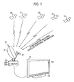
- FIG. 1 is a view illustrating an example of a utilization form of a broadcast receiving apparatus according to the embodiment.
- the broadcast receiving apparatus according to the embodiment is implemented as, e.g., a television apparatus 10.
- the television apparatus 10 can be connected to an antenna apparatus 20.
- the television apparatus 10 has functions of receiving broadcast signals which represent a broadcast program received by the antenna apparatus 20, and displaying images based on the received broadcast signals.
- the antenna apparatus 20 includes an antenna body 21, a motor 22, and a low noise block converter (LNB) 23, and the like.
- the antenna apparatus 20 has function of switching a target satellite from which signals are received by the antenna apparatus 20, among a plurality of satellites 30 to 34, by moving the antenna body 21.
- LNB low noise block converter
- the antenna body 21 has function of receiving a broadcast wave on which a signal sent from a satellite is superposed.
- the antenna body 21 is rotatably connected to the motor 22. The position (or direction) of the antenna body 21 is moved by the rotation of the above motor 22.
- the motor 22 is rotated according to a command input from the television apparatus 10 and moves the antenna body 21.
- the motor 22 includes a motor controller 22a and a storage module 22b.
- the motor controller 22a drives the motor 22 according to the above instruction to change the position (direction) of the antenna body 21.
- the motor controller 22a causes the storage module 22b to store a current reception position (direction) of the antenna body 21.
- the storage module 22b stores, e.g., a movement amount (rotation amount) from an initial position of the motor 22 as information of the reception position (direction).
- the motor controller 22a can control the motor 22 based on the reception position and the initial position stored in the storage module 22b. At that time, the motor controller 22a reads information representing the positions according to a command sent from the television apparatus 10. Then, the motor controller 22a causes the motor 22 to rotate to thereby move the antenna body 21 to the reception position or the initial position, which is represented by the read information.
- the storage module 22b stores the reception position of the antenna body 21 that receives a signal from a satellite, and the preliminarily set initial position of the antenna body 21.
- the LNB 23 amplifies satellite broadcast electric-waves received from a satellite, and functions as a conversion apparatus that converts the frequencies of the amplified electric-waves.
- the LNB 23 functions also as a switching apparatus that changes the polarization of (polarization method for) a satellite broadcast wave received from satellites A and B by the antenna body 21 according to an LNB voltage applied from the television apparatus 10.
- the satellites 30 to 34 are located in, e.g., geostationary orbits above the equator, and transmit satellite broadcast signals including video data, audio data, and service information (SI). Each of the satellites 30 to 34 transmits the SI including satellite positional information that represents an own position.
- SI service information
- the television apparatus 10 can easily control the position (or direction) of the antenna body 21 by displaying, based on satellite positional information included in SI transmitted by each satellite, the satellite positional information representing the position of the satellite having sent signals received by the antenna apparatus 20.
- the television apparatus 10 includes a tuner 101, an LNB controller 102, a separator 103, a control module 104, a decoder 105, a display processor 106, a display module 107, an operation receiver 108, an audio processor 109, and speakers 110.
- the tuner 101 receives, from the antenna apparatus 20, a signal converted by the LNB 23 of the antenna apparatus 20. Then, the tuner 101 extracts a signal of a desired channel. In addition, the tuner 101 performs a process of demodulating a transport stream (TS) from the extracted signal.
- TS transport stream
- the LNB controller 102 sets the polarized waves of broadcast waves by applying an LNB voltage to the LNB 23 of the antenna apparatus 20 via the tuner 101. In addition, the LNB controller 102 applies the LNB voltage to the antenna apparatus 20 as electric power for driving the motor 22.
- the separator 103 separates elementary stream (ES) of video data and audio data, and SI from TSs input from the tuner 101. Then, the separator 103 outputs the separated video data and the separated audio data to the decoder 105 and also outputs the SI to a control module 104.
- ES elementary stream
- the control module 104 includes a graphical user interface (GUI) controller 121, a movement controller 122, a tuning controller 123, a level detection module 124, a position determination module 125, and a notification sound controller 126.
- GUI graphical user interface
- the control module 104 has a function of controlling the antenna apparatus 20.
- the GUI controller 121 has functions of generating a screen displayed by the television apparatus 10, and processing an operation-input to the screen.
- the GUI controller 121 generates a position setting screen for adjusting the position of the antenna body 21 of the antenna apparatus 20, and the like.
- the position setting screen is a screen for performing processes of searching for and storing the position (direction) of the antenna body 21 capable of receiving a signal from a satellite.
- the GUI controller 121 outputs video data representing the generated screen to the display processor 106.
- the GUI controller 121 processes an operation-input to the position setting screen displayed in the display module 107 and outputs to the movement controller 122 an instruction based on the operation-input.
- the movement controller 122 controls the motor 22 of the antenna apparatus 20 and has the function of moving the antenna body 21 by a given amount of movement (or amount of rotation). In response to an instruction input from the GUI controller 121, the movement controller 122 outputs, to the motor 22, a movement instruction to designate a direction of movement (or direction of rotation) and an amount of movement (amount of rotation).
- the movement controller 122 When receiving a position memory instruction from the GUI controller 121, the movement controller 122 outputs the position memory instruction to the antenna apparatus 20 and causes the storage module 22b to store, as a reception position, the position (direction) to which the antenna body 21 is directed. When receiving a stored-position movement instruction from the GUI controller 121, the movement controller 122 outputs the stored-position movement instruction to the motor 22 thereby to move the antenna body 21 to the reception position stored in the antenna apparatus 20.
- the tuning controller 123 sets the polarization of satellite broadcast waves to be received from a satellite, and the frequency and the like of satellite broadcast signals to be received the satellite. At that time, the tuning controller 123 sets, e.g., horizontal polarization or vertical polarization as the polarization of the satellite broadcast waves. When a channel is selected while viewing satellite broadcast, the tuning controller 123 performs tuning, i.e., adjusts the frequency of signals extracted by the turner portion 101 to the frequency of satellite broadcast waves of the selected channel.
- the level detection module 124 detects the signal level of a signal received by the tuner 101 (a signal flow from the tuner 101 to the level detection module 124 is not shown) when the tuner 101 is locked, i.e., when an error rate of an input satellite broadcast signal is equal to or less than a threshold value, and the tuner 101 is enabled to demodulate a satellite broadcast signal.
- the level detection module 124 outputs information concerning the detected reception level to the GUI controller 121.
- the level detection module 124 can output reception level information to the audio processor 109.
- the level detection module 124 detects a plurality of parameters or a single parameter among parameters such as the signal strength and the error rate of a satellite broadcast signal and a carrier-to-noise ratio (C/N ratio). Then, the level detection module 124 detects a signal level according to the detected one or more parameters.
- the position determination module 125 When SI is input from the separator 103, the position determination module 125 extracts satellite positional information included in the SI. Then, the position determination module 125 outputs the extracted satellite positional information to the GUI controller 121. The position determination module 125 determines, based on the extracted positional information, whether a currently received satellite broadcast signal is sent from a satellite to be searched for. The position determination module 125 also outputs a determination result to the GUI controller 121.
- the notification sound controller 126 If the currently received satellite broadcast signal is sent from a given satellite, the notification sound controller 126 outputs, to the audio processor 109, notification sound data for notifying that the currently received satellite broadcast signal is sent from the given satellite. However, the notification sound controller 126 may output, to the audio processor 109, notification sound data representing a sound volume according to, e.g., the reception level of a satellite broadcast signal.
- the decoder 105 decodes TSs input from the separator 103 and generates video data and audio data. Then, the decoder 105 outputs decoded video data to the display processor 106, while outputting decoded audio data to the audio processor 109 (a data-flow from the decoder 105 to the audio processor 109 is not shown).
- the display processor 106 has a function of converting video data input from the GUI controller 121 and the decoder 105 into video signals to be displayed in a display-device. Then, the display processor 106 outputs the converted video signal to the display module 107.
- the display module 107 displays an image according to the video signal.
- the operation receiver 108 receives an input operation from a user interface such as a remote controller.
- the operation receiver 108 receives an input operation to, e.g., a position setting screen displayed by the display module 107. Then, the operation receiver 108 outputs to the GUI controller 121 the received input operation.
- the audio processor 109 converts, into audio signals for speakers, audio data input from the decoder 105 and the notification sound controller 126.
- the audio processor 109 outputs the audio signal to the speakers 110. Then, the speakers 110 outputs sounds represented by the audio signals input thereto.
- SI 300 includes frequency information 301, satellite positional information 302, east/west determination information 303, polarization information 304, modulation method information 305, and symbol rate information 306. These types of information are information concerning a satellite that sends SI 300.
- the frequency information 301 is information concerning a frequency of a satellite broadcast signal transmitted by a satellite.
- the satellite positional information 302 and the east/west determination information 303 are information concerning a position of a satellite.
- the satellite positional information 302 is information indicating, e.g., above what longitude an orbit of a satellite is located.
- the east/west determination information 303 is information indicating which of eastern and western satellite orbits, in each of which a satellite is located, above a longitude of 0.
- the above position determination module 125 extracts, as information representing the position of a satellite, the satellite positional information 302 and the east/west determination information 303 included by the SI.
- the position determination module 125 determines, based on these types of information, the position of a satellite transmitting a currently received satellite broadcast signal.
- the GUI controller 121 converts the information representing the position of a satellite, such as the satellite positional information 302 and the east/west determination information 303, into, e.g., a character string, a graphic, or the like.
- the converted character string or the converted graphic is arranged in the position setting screen as an image indicating a position of a satellite.
- the polarization information 304 indicates what type of polarization of waves the satellite broadcast wave transmitted by a satellite is.
- the modulation method information 305 represents a method for modulating satellite broadcast signals.
- the symbol rate information 306 represents the symbol rate of satellite broadcast signals.
- the SI is information transmitted by each satellite.
- the television apparatus 10 can determine the position of a satellite by acquiring the satellite positional information 302 and the east/west determination information 303 included in the SI that is contained in a satellite broadcast signal received by the antenna apparatus 20. It can be determined by the determination of the position of a satellite serving as a source of a currently received satellite broadcast signal whether the satellite is a predetermined one.
- the SI can contain information, such as identifiers and satellite names, for identifying satellites.
- the television apparatus 10 may determine, based on the information, whether a satellite serving as a reception target is a predetermined one.
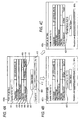
- FIG. 4A shows an example of an initial position setting screen.
- a satellite information display area 401 In the position setting screen 400a, a satellite information display area 401, a cursor 402, an initial return button 403, an initial position movement button 404, a step size change button 405, a manual movement button 406, a position memory button 407, a reception condition display area 408, and the like are arranged.
- the satellite information display area 401 is an area in which information concerning a search target satellite is displayed. An image representing, e.g., the name, the position and the like of the search target satellite is displayed in the area 401.
- the initial return button 403 is a button for moving the antenna body 21 of the antenna apparatus 20 to an origin (initial position).
- the initial position movement button 404 is a button for moving the position (direction) of antenna body 21 to an origin (initial position).
- the initial position movement button 404 is a button for changing the position (direction) of the antenna body 21 to the position stored in the antenna apparatus 20.
- the step size change button 405 is a button for setting an amount of movement (amount of rotation) of the antenna body 21 when an operation-input to the manual movement button 406 is received. For example, a currently set amount 409 of movement thereof is displayed on the button 405.
- the television apparatus 10 sets an amount of movement of the antenna body 21.
- the button 405 may be set such that only the currently set amount of movement thereof is displayed thereon. Alternatively, the currently set amount of movement thereof may be displayed by being emphasized, while information concerning other settable movement amounts is displayed in another display form, e.g., by being grayed out.
- the manual movement button 406 is a button for changing the position (direction) of the antenna body 21.
- An east direction movement button 410 and a west direction movement button 411 are displayed on the button 406.
- the east direction movement button 410 is a button for rotationally moving the antenna body 21 in an eastward direction (clockwise).
- the west direction movement button 411 is a button for rotationally moving the antenna body 21 in a westward direction (counterclockwise).
- the direction of rotating the antenna body 21 in the case of eastwardly or westwardly moving thereof varies with a region in which the antenna apparatus 20 is installed.
- the antenna body 21 in the case of installing thereof in the northern hemisphere is opposite to that of rotating, when eastwardly or westwardly moved, the antenna body 21 in the case of installing thereof in the southern hemisphere.
- the television apparatus 10 When receiving an input operation to the button 410 or 411, the television apparatus 10 outputs to the antenna apparatus 20 a movement instruction according to the operation-input.
- the cursor 402 designates the manual movement button 406
- the television apparatus 10 determines that the button 410 or 411 is selected. Then, the television apparatus 10 outputs to the antenna apparatus 20 a movement instruction to move the antenna body 21 to a position (or in a direction) based on the operation-input.
- the position memory button 407 is button for storing the current position (direction) of the antenna body 21 of the antenna apparatus 20.
- the GUI controller 121 instructs the movement controller 122 to store the current position of the antenna body 21.
- the movement controller 122 stores, e.g., an amount of movement from the initial position of the antenna body 21 of the antenna apparatus 20 as positional information.
- Information on the reception condition of the satellite broadcast signal received by the antenna apparatus 20 is displayed in the reception condition display area 408.
- an image of a gauge 412, the numerical value 413 of a reception level, or the like is displayed in the reception condition display area 408 as information representing a reception condition.
- a position setting screen 400b illustrated in FIG. 4B is an example of the screen displayed when the tuner 101 receives a satellite broadcast signal from a satellite which is different from the search target satellite.
- a position setting screen 400c illustrated in FIG. 4C is an example of the screen displayed when the tuner 101 receives a satellite broadcast signal from the search target satellite.
- a current position display area 420 is displayed in each of the position setting screens 400b and 400c.
- An image representing information concerning a satellite which transmits satellite broadcast signals received by the television apparatus 10 is displayed in the current position display area 420.
- the television apparatus 10 extracts satellite positional information or the like from SI superposed on currently received satellite broadcast signals.
- the television apparatus 10 displays the extracted positional information in the current position display area 420. For example, an image representing the numerical value of the direction of a satellite's orbit is displayed in the current position display area 420 as satellite positional information.
- the television apparatus 10 displays satellite positional information representing the position of the satellite that transmits a satellite broadcast signal received by the tuner 101. Consequently, a user can recognize not only whether the satellite from which a satellite broadcast signal is currently received is the predetermined satellite, but the position of the satellite from which a satellite broadcast signal is currently received.
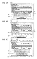
- FIGS. 5A and 5B show examples of the position setting screen displayed when the television apparatus 10 receives a satellite broadcast signal from a satellite differing from a predetermined search target satellite.
- Images representing the following types of information are displayed in the current position display area 420 of the position setting screen of the position setting screen 500a shown in FIG. 5A . That is, the images represent not only positional information representing the position of a satellite from which a satellite broadcast signal is currently received, but the difference in position (or direction) between the satellite from which a satellite broadcast signal is currently received, and the search target satellite, the name of the satellite from which a satellite broadcast signal is currently received, the fact that the satellite broadcast signal currently received differs from the search target satellite, and the like.
- the difference in position between the satellites can be calculated based on information representing the positions (or directions) of the two satellites, the longitude and the latitude of a position at which the antenna apparatus 20 is installed, and the radius of the earth.
- the television apparatus 10 can acquire, from the SI, information representing the position of the satellite from which a signal is currently received, and can acquire information representing the position of the search target satellite, and information representing the position of own equipment by, e.g., an input operation from a user.
- one of the east direction movement button 410 and the west direction movement button 411 corresponds to the movement towards the position (or direction) of the search target satellite and is displayed by being more emphasized, as compared with the display of the other of the buttons 410 and 411.
- images to be displayed in the position memory button 407 and the reception condition display area 408 are displayed in the position setting screen 500a in a display form such as a grayed-out form.
- the display form of images according to the invention is not limited to the grayed-out form. Any other display form can be employed, as long as the display form is changed according to whether a transmission-source satellite from which a satellite broadcast signal is currently received is the predetermined search target satellite.
- the position memory button 407 may be set in the position setting screen 500a to be non-displayed and to be unselectable. Images of the gauge 412 and the numerical value of a reception level 413 may be non-displayed in the reception condition display area 408.
- a position map is displayed in the current positional information display area 420. Images respectively indicating the current position of the satellite transmitting satellite broadcast signals currently received, and the position of the search target satellite are displayed in the position map.
- the position setting screen 500c is an example of the screen displayed when the television apparatus 10 receives satellite broadcast signals from the search target satellite.
- the screen 500c displays, in the current positional information display area 420, the current position, the name of the satellite from which a satellite broadcast signal is currently received, and the fact that the satellite broadcast signal is received.
- Information displayed in the position memory button 407 and the reception condition display area 408 is displayed by being more emphasized, as compared with the case of receiving signals from a satellite that is not the search target satellite.
- the position memory button 407 in the screen 500c, or the entire screen may be set to blink.
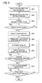
- step S601 the television apparatus 10 displays an antenna position setting screen. Then, in step S602, the television apparatus 10 receives an input operation for instructing to change the position (or direction) of the antenna body 21 of the antenna apparatus 20.
- the television apparatus 10 receives input operations for instructing movement, e.g., a "RETURN TO ORIGIN” input operation, a "STORE POSITION” input operation, and a "MANUAL MOVEMENT” input operation described with reference to FIG. 4A .
- step S603 the television apparatus 10 outputs a movement instruction based on an input operation to the setting screen to the antenna apparatus 20. If the antenna apparatus 20 receives a satellite broadcast signal and the tuner 101 receives the received satellite broadcast signal (Yes in step S604), in step S605, the television apparatus 10 displays the signal level of the signal received by the tuner 101. Then, if the tuner 101 receives a satellite broadcast signal, in step S606, the television apparatus 10 extracts SI contained in the satellite broadcast signal and also extracts satellite positional information contained in the SI.
- step S607 based on the extracted positional information, the television apparatus 10 determines the position of the satellite transmitting the satellite broadcast signal currently received by the antenna apparatus 20 and also determines whether this satellite is the search target satellite.
- step S608 based on the extracted satellite positional information, the television apparatus 10 displays positional information representing the position of the transmission-source satellite transmitting the currently received satellite broadcast signal.
- the television apparatus 10 may change the display form of the operation button and the reception level according to whether the satellite from which a signal is currently received is the search target satellite. Alternatively, the display form of the entire screen may be changed.
- step S609 the television apparatus 10 determines whether the television apparatus 10 receives a "STORE POSITION" input operation. If the television apparatus 10 receives a "STORE POSITION” input operation (Yes in step S609), in step S610, the television apparatus 10 outputs a "STORE POSITION” instruction to the antenna apparatus 20 and causes the antenna apparatus 20 to store the current position (or direction) of the antenna body 21. On the other hand, if the position of the antenna 21 is further moved, i.e., the television apparatus 10 doesn't receive a "STORE POSITION” input operation (No in step S609), the television apparatus 10 performs processing in step S602 and receives an input operation for setting antenna position again.
- the television apparatus 10 can set a plurality of satellites as search targets whose positions are stored.
- step S611 the television apparatus 10 determines whether positions are set for all search target satellites. If the positions of all satellites are set and stored (Yes in step S611), the flow of the process is completed. If there are satellites whose positions are neither set nor stored (No in step S611), the television apparatus 100 performs processing in step S601. Then, the television apparatus 10 displays an antenna position setting screen corresponding to each of the satellites whose positions are unset.
- the antenna apparatus 20 moves the antenna body 21 to search for a position at which the antenna apparatus 20 receives satellite broadcast signals from the predetermined satellite.
- the apparatus according to the embodiment is not limited thereto. That is, when a position at which signals are received from the predetermined satellite is searched for, the television apparatus 10 can cause the antenna body 21, without receiving an input operation from a user, to scan. In this case, the television apparatus 10 extracts information such as satellite positional information from SI contained in satellite broadcast signals received from the antenna apparatus 20 during scanning. Then, the television apparatus 10 determines, based on the extracted information, whether a transmission-source satellite transmitting currently received satellite broadcast signals is the predetermined satellite.
- the television apparatus 10 may store the position of a satellite in a case that the satellite is a predetermined search target satellite and the reception level is equal to or higher than a predetermined value.
- positional information representing the position at which signals from a predetermined satellite are received is stored in the storage module 22b of the antenna apparatus 20.
- the television apparatus 10 may store the positional information.
Landscapes
- Circuits Of Receivers In General (AREA)
Abstract
According to one embodiment, there is provided a broadcast receiving apparatus which is connectable to an antenna apparatus configured to move a position of an antenna according to an input control signal. The broadcast receiving apparatus includes: a receiver which receives, from the antenna apparatus, a satellite broadcast signal containing positional information of a satellite; a display controller which displays, in a display apparatus, a screen including a first image showing a position of the satellite based on the positional information of the satellite, and a second image for moving a position of the antenna; and an output module which outputs, to the antenna apparatus, a control signal which controls the position of the antenna based on an input operation with respect to the second image.
Description
- Embodiments described herein relate generally to a broadcast receiving apparatus, an image output method and a program.
- There are techniques of a receiving apparatus capable of changing a receiving target satellite by rotating a motor to change the direction of an antenna. The receiving apparatus transmits control signals to the motor of the antenna. Consequently, the receiving apparatus rotates the antenna to adjust the direction of the antenna to the azimuth angle of a predetermined satellite. Thus, the receiving apparatus receives satellite broadcast signals of a user's desired program.
- When the direction of the antenna is adjusted to the predetermined satellite, the apparatus preliminarily stores antenna positional information representing the position of the antenna, at which the antenna can receive signals from the predetermined satellite. The apparatus controls the antenna's position based on the stored positional information. Thus, when the receiving apparatus is utilized, it is necessary for the apparatus to search for a good-position of the antenna, at which the antenna can favorably receive satellite broadcast signals, by preliminarily adjusting the antenna's position, and to store the good-position searched for.
- When the position for receiving satellite broadcast signals is searched for by adjustment of the position of the antenna, it is desirable to easily perform the adjustment.
-
-
FIG. 1 is a view illustrating a utilization form of a television apparatus according to an embodiment. -
FIG. 2 is a view illustrating an example of a system configuration of the television apparatus according to the embodiment. -
FIG. 3 is a view illustrating an example of a data structure of service information (SI) received by the television apparatus according to the embodiment. -
FIGS. 4A, 4B, and 4C are views respectively illustrating examples of an antenna direction setting screen displayed by the television apparatus according to the embodiment. -
FIG. 5A, 5B, and 5C are views respectively illustrating examples of the antenna direction setting screen displayed by the television apparatus according to the embodiment. -
FIG. 6 is a flowchart illustrating an example of flow of an antenna direction setting process performed by the television apparatus according to the embodiment. - Hereinafter, an embodiment of the invention is described with reference to the drawings.
-
FIG. 1 is a view illustrating an example of a utilization form of a broadcast receiving apparatus according to the embodiment. The broadcast receiving apparatus according to the embodiment is implemented as, e.g., atelevision apparatus 10. Thetelevision apparatus 10 can be connected to anantenna apparatus 20. Thetelevision apparatus 10 has functions of receiving broadcast signals which represent a broadcast program received by theantenna apparatus 20, and displaying images based on the received broadcast signals. - The
antenna apparatus 20 includes anantenna body 21, amotor 22, and a low noise block converter (LNB) 23, and the like. Theantenna apparatus 20 has function of switching a target satellite from which signals are received by theantenna apparatus 20, among a plurality ofsatellites 30 to 34, by moving theantenna body 21. - The
antenna body 21 has function of receiving a broadcast wave on which a signal sent from a satellite is superposed. In addition, theantenna body 21 is rotatably connected to themotor 22. The position (or direction) of theantenna body 21 is moved by the rotation of theabove motor 22. - The
motor 22 is rotated according to a command input from thetelevision apparatus 10 and moves theantenna body 21. Themotor 22 includes amotor controller 22a and astorage module 22b. When a movement instruction to designate a movement direction (rotation direction) and a movement amount (rotation amount) of theantenna body 21 is input from thebroadcast receiving apparatus 10, themotor controller 22a drives themotor 22 according to the above instruction to change the position (direction) of theantenna body 21. - When a position memory instruction is input from the
television apparatus 10, themotor controller 22a causes thestorage module 22b to store a current reception position (direction) of theantenna body 21. Thestorage module 22b stores, e.g., a movement amount (rotation amount) from an initial position of themotor 22 as information of the reception position (direction). - In addition, the
motor controller 22a can control themotor 22 based on the reception position and the initial position stored in thestorage module 22b. At that time, themotor controller 22a reads information representing the positions according to a command sent from thetelevision apparatus 10. Then, themotor controller 22a causes themotor 22 to rotate to thereby move theantenna body 21 to the reception position or the initial position, which is represented by the read information. Thestorage module 22b stores the reception position of theantenna body 21 that receives a signal from a satellite, and the preliminarily set initial position of theantenna body 21. - The LNB 23 amplifies satellite broadcast electric-waves received from a satellite, and functions as a conversion apparatus that converts the frequencies of the amplified electric-waves. The LNB 23 functions also as a switching apparatus that changes the polarization of (polarization method for) a satellite broadcast wave received from satellites A and B by the
antenna body 21 according to an LNB voltage applied from thetelevision apparatus 10. - The
satellites 30 to 34 are located in, e.g., geostationary orbits above the equator, and transmit satellite broadcast signals including video data, audio data, and service information (SI). Each of thesatellites 30 to 34 transmits the SI including satellite positional information that represents an own position. - The
television apparatus 10 can easily control the position (or direction) of theantenna body 21 by displaying, based on satellite positional information included in SI transmitted by each satellite, the satellite positional information representing the position of the satellite having sent signals received by theantenna apparatus 20. - Next, the functional blocks of the
television apparatus 10 according to the embodiment are described hereinafter with reference toFIG. 2 . - The
television apparatus 10 includes atuner 101, an LNBcontroller 102, aseparator 103, acontrol module 104, adecoder 105, adisplay processor 106, adisplay module 107, anoperation receiver 108, anaudio processor 109, andspeakers 110. - The
tuner 101 receives, from theantenna apparatus 20, a signal converted by the LNB 23 of theantenna apparatus 20. Then, thetuner 101 extracts a signal of a desired channel. In addition, thetuner 101 performs a process of demodulating a transport stream (TS) from the extracted signal. - The
LNB controller 102 sets the polarized waves of broadcast waves by applying an LNB voltage to theLNB 23 of theantenna apparatus 20 via thetuner 101. In addition, the LNBcontroller 102 applies the LNB voltage to theantenna apparatus 20 as electric power for driving themotor 22. - The
separator 103 separates elementary stream (ES) of video data and audio data, and SI from TSs input from thetuner 101. Then, theseparator 103 outputs the separated video data and the separated audio data to thedecoder 105 and also outputs the SI to acontrol module 104. - The
control module 104 includes a graphical user interface (GUI)controller 121, amovement controller 122, atuning controller 123, alevel detection module 124, aposition determination module 125, and anotification sound controller 126. Thecontrol module 104 has a function of controlling theantenna apparatus 20. - The
GUI controller 121 has functions of generating a screen displayed by thetelevision apparatus 10, and processing an operation-input to the screen. TheGUI controller 121 generates a position setting screen for adjusting the position of theantenna body 21 of theantenna apparatus 20, and the like. The position setting screen is a screen for performing processes of searching for and storing the position (direction) of theantenna body 21 capable of receiving a signal from a satellite. - The
GUI controller 121 outputs video data representing the generated screen to thedisplay processor 106. TheGUI controller 121 processes an operation-input to the position setting screen displayed in thedisplay module 107 and outputs to themovement controller 122 an instruction based on the operation-input. - The
movement controller 122 controls themotor 22 of theantenna apparatus 20 and has the function of moving theantenna body 21 by a given amount of movement (or amount of rotation). In response to an instruction input from theGUI controller 121, themovement controller 122 outputs, to themotor 22, a movement instruction to designate a direction of movement (or direction of rotation) and an amount of movement (amount of rotation). - When receiving a position memory instruction from the
GUI controller 121, themovement controller 122 outputs the position memory instruction to theantenna apparatus 20 and causes thestorage module 22b to store, as a reception position, the position (direction) to which theantenna body 21 is directed. When receiving a stored-position movement instruction from theGUI controller 121, themovement controller 122 outputs the stored-position movement instruction to themotor 22 thereby to move theantenna body 21 to the reception position stored in theantenna apparatus 20. - The tuning
controller 123 sets the polarization of satellite broadcast waves to be received from a satellite, and the frequency and the like of satellite broadcast signals to be received the satellite. At that time, the tuningcontroller 123 sets, e.g., horizontal polarization or vertical polarization as the polarization of the satellite broadcast waves. When a channel is selected while viewing satellite broadcast, the tuningcontroller 123 performs tuning, i.e., adjusts the frequency of signals extracted by theturner portion 101 to the frequency of satellite broadcast waves of the selected channel. - The
level detection module 124 detects the signal level of a signal received by the tuner 101 (a signal flow from thetuner 101 to thelevel detection module 124 is not shown) when thetuner 101 is locked, i.e., when an error rate of an input satellite broadcast signal is equal to or less than a threshold value, and thetuner 101 is enabled to demodulate a satellite broadcast signal. - The
level detection module 124 outputs information concerning the detected reception level to theGUI controller 121. Thelevel detection module 124 can output reception level information to theaudio processor 109. Thelevel detection module 124 detects a plurality of parameters or a single parameter among parameters such as the signal strength and the error rate of a satellite broadcast signal and a carrier-to-noise ratio (C/N ratio). Then, thelevel detection module 124 detects a signal level according to the detected one or more parameters. - When SI is input from the
separator 103, theposition determination module 125 extracts satellite positional information included in the SI. Then, theposition determination module 125 outputs the extracted satellite positional information to theGUI controller 121. Theposition determination module 125 determines, based on the extracted positional information, whether a currently received satellite broadcast signal is sent from a satellite to be searched for. Theposition determination module 125 also outputs a determination result to theGUI controller 121. - If the currently received satellite broadcast signal is sent from a given satellite, the
notification sound controller 126 outputs, to theaudio processor 109, notification sound data for notifying that the currently received satellite broadcast signal is sent from the given satellite. However, thenotification sound controller 126 may output, to theaudio processor 109, notification sound data representing a sound volume according to, e.g., the reception level of a satellite broadcast signal. - The
decoder 105 decodes TSs input from theseparator 103 and generates video data and audio data. Then, thedecoder 105 outputs decoded video data to thedisplay processor 106, while outputting decoded audio data to the audio processor 109 (a data-flow from thedecoder 105 to theaudio processor 109 is not shown). - The
display processor 106 has a function of converting video data input from theGUI controller 121 and thedecoder 105 into video signals to be displayed in a display-device. Then, thedisplay processor 106 outputs the converted video signal to thedisplay module 107. Thedisplay module 107 displays an image according to the video signal. - The
operation receiver 108 receives an input operation from a user interface such as a remote controller. Theoperation receiver 108 receives an input operation to, e.g., a position setting screen displayed by thedisplay module 107. Then, theoperation receiver 108 outputs to theGUI controller 121 the received input operation. - The
audio processor 109 converts, into audio signals for speakers, audio data input from thedecoder 105 and thenotification sound controller 126. Theaudio processor 109 outputs the audio signal to thespeakers 110. Then, thespeakers 110 outputs sounds represented by the audio signals input thereto. - Next, an example of the data structure of SI included by satellite broadcast signals received by the
antenna apparatus 20 is described with reference toFIG. 3 . -
SI 300 includesfrequency information 301, satellitepositional information 302, east/west determination information 303,polarization information 304,modulation method information 305, andsymbol rate information 306. These types of information are information concerning a satellite that sendsSI 300. - The
frequency information 301 is information concerning a frequency of a satellite broadcast signal transmitted by a satellite. The satellitepositional information 302 and the east/west determination information 303 are information concerning a position of a satellite. The satellitepositional information 302 is information indicating, e.g., above what longitude an orbit of a satellite is located. The east/west determination information 303 is information indicating which of eastern and western satellite orbits, in each of which a satellite is located, above a longitude of 0. The aboveposition determination module 125 extracts, as information representing the position of a satellite, the satellitepositional information 302 and the east/west determination information 303 included by the SI. Theposition determination module 125 determines, based on these types of information, the position of a satellite transmitting a currently received satellite broadcast signal. TheGUI controller 121 converts the information representing the position of a satellite, such as the satellitepositional information 302 and the east/west determination information 303, into, e.g., a character string, a graphic, or the like. The converted character string or the converted graphic is arranged in the position setting screen as an image indicating a position of a satellite. - The
polarization information 304 indicates what type of polarization of waves the satellite broadcast wave transmitted by a satellite is. Themodulation method information 305 represents a method for modulating satellite broadcast signals. Thesymbol rate information 306 represents the symbol rate of satellite broadcast signals. - The SI is information transmitted by each satellite. Thus, the
television apparatus 10 can determine the position of a satellite by acquiring the satellitepositional information 302 and the east/west determination information 303 included in the SI that is contained in a satellite broadcast signal received by theantenna apparatus 20. It can be determined by the determination of the position of a satellite serving as a source of a currently received satellite broadcast signal whether the satellite is a predetermined one. The SI can contain information, such as identifiers and satellite names, for identifying satellites. Thetelevision apparatus 10 may determine, based on the information, whether a satellite serving as a reception target is a predetermined one. - Next, an example of a position setting screen displayed by the
television apparatus 10 is described with reference toFIGS. 4A to 4C . -
FIG. 4A shows an example of an initial position setting screen. - In the
position setting screen 400a, a satelliteinformation display area 401, acursor 402, aninitial return button 403, an initialposition movement button 404, a stepsize change button 405, amanual movement button 406, aposition memory button 407, a receptioncondition display area 408, and the like are arranged. - The satellite
information display area 401 is an area in which information concerning a search target satellite is displayed. An image representing, e.g., the name, the position and the like of the search target satellite is displayed in thearea 401. - The
initial return button 403 is a button for moving theantenna body 21 of theantenna apparatus 20 to an origin (initial position). The initialposition movement button 404 is a button for moving the position (direction) ofantenna body 21 to an origin (initial position). The initialposition movement button 404 is a button for changing the position (direction) of theantenna body 21 to the position stored in theantenna apparatus 20. - The step
size change button 405 is a button for setting an amount of movement (amount of rotation) of theantenna body 21 when an operation-input to themanual movement button 406 is received. For example, a currently setamount 409 of movement thereof is displayed on thebutton 405. When receiving an input operation to thebutton 405, thetelevision apparatus 10 sets an amount of movement of theantenna body 21. Thebutton 405 may be set such that only the currently set amount of movement thereof is displayed thereon. Alternatively, the currently set amount of movement thereof may be displayed by being emphasized, while information concerning other settable movement amounts is displayed in another display form, e.g., by being grayed out. - The
manual movement button 406 is a button for changing the position (direction) of theantenna body 21. An eastdirection movement button 410 and a westdirection movement button 411 are displayed on thebutton 406. The eastdirection movement button 410 is a button for rotationally moving theantenna body 21 in an eastward direction (clockwise). The westdirection movement button 411 is a button for rotationally moving theantenna body 21 in a westward direction (counterclockwise). Sometimes, the direction of rotating theantenna body 21 in the case of eastwardly or westwardly moving thereof varies with a region in which theantenna apparatus 20 is installed. That is, e.g., the direction of rotating, when eastwardly or westwardly moved, theantenna body 21 in the case of installing thereof in the northern hemisphere is opposite to that of rotating, when eastwardly or westwardly moved, theantenna body 21 in the case of installing thereof in the southern hemisphere. - When receiving an input operation to the
button television apparatus 10 outputs to the antenna apparatus 20 a movement instruction according to the operation-input. In a case where thecursor 402 designates themanual movement button 406, when receiving an operation-input to left and right buttons of an operation-input device such as a remote controller (not shown), thetelevision apparatus 10 determines that thebutton television apparatus 10 outputs to the antenna apparatus 20 a movement instruction to move theantenna body 21 to a position (or in a direction) based on the operation-input. - The
position memory button 407 is button for storing the current position (direction) of theantenna body 21 of theantenna apparatus 20. When receiving an operation-input to thebutton 407, theGUI controller 121 instructs themovement controller 122 to store the current position of theantenna body 21. Themovement controller 122 stores, e.g., an amount of movement from the initial position of theantenna body 21 of theantenna apparatus 20 as positional information. - Information on the reception condition of the satellite broadcast signal received by the
antenna apparatus 20 is displayed in the receptioncondition display area 408. For example, an image of agauge 412, thenumerical value 413 of a reception level, or the like is displayed in the receptioncondition display area 408 as information representing a reception condition. - Next, an example of a position setting screen displayed by the
television apparatus 10 in the case of receiving and locking satellite broadcast signals by thetuner 101 is described with reference toFIGS. 4B and 4C . - A
position setting screen 400b illustrated inFIG. 4B is an example of the screen displayed when thetuner 101 receives a satellite broadcast signal from a satellite which is different from the search target satellite. Aposition setting screen 400c illustrated inFIG. 4C is an example of the screen displayed when thetuner 101 receives a satellite broadcast signal from the search target satellite. - A current
position display area 420 is displayed in each of the position setting screens 400b and 400c. An image representing information concerning a satellite which transmits satellite broadcast signals received by thetelevision apparatus 10 is displayed in the currentposition display area 420. Thetelevision apparatus 10 extracts satellite positional information or the like from SI superposed on currently received satellite broadcast signals. Thetelevision apparatus 10 displays the extracted positional information in the currentposition display area 420. For example, an image representing the numerical value of the direction of a satellite's orbit is displayed in the currentposition display area 420 as satellite positional information. - Even when the
tuner 101 locks and receives a satellite broadcast signal, the satellite broadcast signal is not always a signal transmitted from the predetermined search target satellite. Thus, thetelevision apparatus 10 displays satellite positional information representing the position of the satellite that transmits a satellite broadcast signal received by thetuner 101. Consequently, a user can recognize not only whether the satellite from which a satellite broadcast signal is currently received is the predetermined satellite, but the position of the satellite from which a satellite broadcast signal is currently received. - In addition, another manner of the position setting screen is described hereinafter with reference to
FIGS. 5A to 5C . -
FIGS. 5A and 5B show examples of the position setting screen displayed when thetelevision apparatus 10 receives a satellite broadcast signal from a satellite differing from a predetermined search target satellite. Images representing the following types of information are displayed in the currentposition display area 420 of the position setting screen of theposition setting screen 500a shown inFIG. 5A . That is, the images represent not only positional information representing the position of a satellite from which a satellite broadcast signal is currently received, but the difference in position (or direction) between the satellite from which a satellite broadcast signal is currently received, and the search target satellite, the name of the satellite from which a satellite broadcast signal is currently received, the fact that the satellite broadcast signal currently received differs from the search target satellite, and the like. - The difference in position between the satellites can be calculated based on information representing the positions (or directions) of the two satellites, the longitude and the latitude of a position at which the
antenna apparatus 20 is installed, and the radius of the earth. Thetelevision apparatus 10 can acquire, from the SI, information representing the position of the satellite from which a signal is currently received, and can acquire information representing the position of the search target satellite, and information representing the position of own equipment by, e.g., an input operation from a user. - In the
position setting screen 500a, one of the eastdirection movement button 410 and the westdirection movement button 411 corresponds to the movement towards the position (or direction) of the search target satellite and is displayed by being more emphasized, as compared with the display of the other of thebuttons position memory button 407 and the receptioncondition display area 408 are displayed in theposition setting screen 500a in a display form such as a grayed-out form. The display form of images according to the invention is not limited to the grayed-out form. Any other display form can be employed, as long as the display form is changed according to whether a transmission-source satellite from which a satellite broadcast signal is currently received is the predetermined search target satellite. In addition, because the position (or direction) of theantenna body 21 of theantenna apparatus 20 is not a position at which signals from the search target satellite cannot be received, theposition memory button 407 may be set in theposition setting screen 500a to be non-displayed and to be unselectable. Images of thegauge 412 and the numerical value of areception level 413 may be non-displayed in the receptioncondition display area 408. - Next, the
position setting screen 500b is described hereinafter. In theposition setting screen 500b, a position map is displayed in the current positionalinformation display area 420. Images respectively indicating the current position of the satellite transmitting satellite broadcast signals currently received, and the position of the search target satellite are displayed in the position map. - Next, the
position setting screen 500c is described hereinafter. Theposition setting screen 500c is an example of the screen displayed when thetelevision apparatus 10 receives satellite broadcast signals from the search target satellite. - The
screen 500c displays, in the current positionalinformation display area 420, the current position, the name of the satellite from which a satellite broadcast signal is currently received, and the fact that the satellite broadcast signal is received. Information displayed in theposition memory button 407 and the receptioncondition display area 408 is displayed by being more emphasized, as compared with the case of receiving signals from a satellite that is not the search target satellite. Theposition memory button 407 in thescreen 500c, or the entire screen may be set to blink. - Next, an example of flow of a process of performing the adjustment of the position of the
antenna apparatus 20 by thetelevision apparatus 10 is described hereinafter with reference toFIG. 6 . - First, in step S601, the
television apparatus 10 displays an antenna position setting screen. Then, in step S602, thetelevision apparatus 10 receives an input operation for instructing to change the position (or direction) of theantenna body 21 of theantenna apparatus 20. Thetelevision apparatus 10 receives input operations for instructing movement, e.g., a "RETURN TO ORIGIN" input operation, a "STORE POSITION" input operation, and a "MANUAL MOVEMENT" input operation described with reference toFIG. 4A . - Then, in step S603, the
television apparatus 10 outputs a movement instruction based on an input operation to the setting screen to theantenna apparatus 20. If theantenna apparatus 20 receives a satellite broadcast signal and thetuner 101 receives the received satellite broadcast signal (Yes in step S604), in step S605, thetelevision apparatus 10 displays the signal level of the signal received by thetuner 101. Then, if thetuner 101 receives a satellite broadcast signal, in step S606, thetelevision apparatus 10 extracts SI contained in the satellite broadcast signal and also extracts satellite positional information contained in the SI. - Then, in step S607, based on the extracted positional information, the
television apparatus 10 determines the position of the satellite transmitting the satellite broadcast signal currently received by theantenna apparatus 20 and also determines whether this satellite is the search target satellite. In step S608, based on the extracted satellite positional information, thetelevision apparatus 10 displays positional information representing the position of the transmission-source satellite transmitting the currently received satellite broadcast signal. As described above with reference toFIGS. 5A to 5C , thetelevision apparatus 10 may change the display form of the operation button and the reception level according to whether the satellite from which a signal is currently received is the search target satellite. Alternatively, the display form of the entire screen may be changed. - Next, in step S609, the
television apparatus 10 determines whether thetelevision apparatus 10 receives a "STORE POSITION" input operation. If thetelevision apparatus 10 receives a "STORE POSITION" input operation (Yes in step S609), in step S610, thetelevision apparatus 10 outputs a "STORE POSITION" instruction to theantenna apparatus 20 and causes theantenna apparatus 20 to store the current position (or direction) of theantenna body 21. On the other hand, if the position of theantenna 21 is further moved, i.e., thetelevision apparatus 10 doesn't receive a "STORE POSITION" input operation (No in step S609), thetelevision apparatus 10 performs processing in step S602 and receives an input operation for setting antenna position again. - The
television apparatus 10 can set a plurality of satellites as search targets whose positions are stored. In step S611, thetelevision apparatus 10 determines whether positions are set for all search target satellites. If the positions of all satellites are set and stored (Yes in step S611), the flow of the process is completed. If there are satellites whose positions are neither set nor stored (No in step S611), the television apparatus 100 performs processing in step S601. Then, thetelevision apparatus 10 displays an antenna position setting screen corresponding to each of the satellites whose positions are unset. - It has been described that, in the embodiment, based on a user's input operation to the position setting screen, the
antenna apparatus 20 moves theantenna body 21 to search for a position at which theantenna apparatus 20 receives satellite broadcast signals from the predetermined satellite. However, the apparatus according to the embodiment is not limited thereto. That is, when a position at which signals are received from the predetermined satellite is searched for, thetelevision apparatus 10 can cause theantenna body 21, without receiving an input operation from a user, to scan. In this case, thetelevision apparatus 10 extracts information such as satellite positional information from SI contained in satellite broadcast signals received from theantenna apparatus 20 during scanning. Then, thetelevision apparatus 10 determines, based on the extracted information, whether a transmission-source satellite transmitting currently received satellite broadcast signals is the predetermined satellite. Thetelevision apparatus 10 may store the position of a satellite in a case that the satellite is a predetermined search target satellite and the reception level is equal to or higher than a predetermined value. - It has also been described that positional information representing the position at which signals from a predetermined satellite are received is stored in the
storage module 22b of theantenna apparatus 20. However, thetelevision apparatus 10 may store the positional information. - While certain embodiment has been described, the exemplary embodiment has been presented by way of example only, and is not intended to limit the scope of the inventions. Indeed, the novel methods and systems described herein may be embodied in a variety of other forms; furthermore, various omissions, substitutions and changes in the form of the methods and systems described herein may be made without departing from the spirit of the inventions. The accompanying claims and their equivalents are intended to cover such forms or modifications as would fall within the scope and spirit of the inventions.
Claims (11)
- A broadcast receiving apparatus which is connectable to an antenna apparatus configured to move a position of an antenna according to an input control signal, comprising:a receiver configured to receive, from the antenna apparatus, a satellite broadcast signal containing positional information of a satellite;a display controller configured to display, in a display apparatus, a screen including a first image showing a position of the satellite based on the positional information of the satellite, and a second image for moving a position of the antenna; andan output module configured to output, to the antenna apparatus, a control signal which controls the position of the antenna based on an input operation with respect to the second image.
- The apparatus of claim 1, wherein the display controller causes the display apparatus to display the screen further including a third image showing a position of a given satellite different from the satellite whose position is represented by the positional information.
- The apparatus of claim 1 further comprising:a detector configured to detect a signal level of the satellite broadcast signal,wherein the display controller causes the display apparatus to display the screen including a fourth image showing the detected signal level.
- The apparatus of claim 1, wherein the display controller causes the display apparatus to display the screen in a display format varying with whether the satellite broadcast signal input to an input module is a signal transmitted from a given satellite.
- The apparatus of claim 1, wherein the display controller causes the display apparatus to display a name of the satellite together with the first image.
- The apparatus of claim 2 further comprising:an audio output module configured to output a notification sound when the satellite broadcast signal input to an input module is a signal transmitted from a given satellite.
- The apparatus of claim 6, wherein the audio output module is configured to output the notification sound whose volume corresponds to the detected signal level.
- The apparatus of claim 1, wherein the display controller causes the display apparatus to display the screen containing a fifth image showing a difference in position between a satellite which transmits the satellite broadcast signal and a given satellite.
- The apparatus of claim 1 further comprising: the display apparatus.
- An image output method in an apparatus connectable to an antenna apparatus configured to move a position of an antenna according to an input control signal, comprising:outputting a control signal which controls a position of the antenna apparatus;receiving, from the antenna apparatus, a satellite broadcast signal containing positional information of a satellite;outputting, based on the positional information, to a display apparatus an image showing a position of the satellite.
- A program for controlling an antenna apparatus in which a position of an antenna is moved according to an input control signal, and for causing a computer to execute the steps of:outputting a control signal for controlling a position of the antenna apparatus;receiving, from the antenna apparatus, a satellite broadcast signal containing positional information of a satellite; andoutputting, based on the positional information, to a display apparatus an image showing a position of the satellite.
Applications Claiming Priority (1)
| Application Number | Priority Date | Filing Date | Title |
|---|---|---|---|
| JP2010201382 | 2010-09-08 |
Publications (1)
| Publication Number | Publication Date |
|---|---|
| EP2429029A1 true EP2429029A1 (en) | 2012-03-14 |
Family
ID=44675411
Family Applications (1)
| Application Number | Title | Priority Date | Filing Date |
|---|---|---|---|
| EP11159458A Withdrawn EP2429029A1 (en) | 2010-09-08 | 2011-03-23 | Broadcast receiving apparatus, image output method, and program |
Country Status (1)
| Country | Link |
|---|---|
| EP (1) | EP2429029A1 (en) |
Cited By (1)
| Publication number | Priority date | Publication date | Assignee | Title |
|---|---|---|---|---|
| EP3094013A4 (en) * | 2014-01-08 | 2017-08-09 | Kabushiki Kaisha Toshiba | Satellite communication system |
Citations (3)
| Publication number | Priority date | Publication date | Assignee | Title |
|---|---|---|---|---|
| EP0963067A2 (en) * | 1998-06-05 | 1999-12-08 | Handan BroadInfoCom | Receiver for receiving satellite broadcast programmes, comprising a control system for automatically controlling the direction of the antenna |
| US20050113032A1 (en) * | 2003-11-21 | 2005-05-26 | Franck Adam | Reception system including a pointing aid device |
| DE202007000905U1 (en) * | 2007-01-17 | 2007-08-23 | Rosenbusch, Michael | Display device for installation assistance of satellite reception systems |
-
2011
- 2011-03-23 EP EP11159458A patent/EP2429029A1/en not_active Withdrawn
Patent Citations (3)
| Publication number | Priority date | Publication date | Assignee | Title |
|---|---|---|---|---|
| EP0963067A2 (en) * | 1998-06-05 | 1999-12-08 | Handan BroadInfoCom | Receiver for receiving satellite broadcast programmes, comprising a control system for automatically controlling the direction of the antenna |
| US20050113032A1 (en) * | 2003-11-21 | 2005-05-26 | Franck Adam | Reception system including a pointing aid device |
| DE202007000905U1 (en) * | 2007-01-17 | 2007-08-23 | Rosenbusch, Michael | Display device for installation assistance of satellite reception systems |
Non-Patent Citations (1)
| Title |
|---|
| "TechniStar S1 Manual", 1 May 2010 (2010-05-01), XP055016170, Retrieved from the Internet <URL:http://www.technisat-daun-fs.de/assets/medias/docus/22/bda_technistar_s1_001.pdf> [retrieved on 20120111] * |
Cited By (1)
| Publication number | Priority date | Publication date | Assignee | Title |
|---|---|---|---|---|
| EP3094013A4 (en) * | 2014-01-08 | 2017-08-09 | Kabushiki Kaisha Toshiba | Satellite communication system |
Similar Documents
| Publication | Publication Date | Title |
|---|---|---|
| US20070113247A1 (en) | Method and apparatus for providing user interface | |
| KR20150043876A (en) | Method and device for searching satellite channels | |
| JP2007006356A (en) | Remote control system, remote controller, and display control method | |
| US20140348485A1 (en) | Image signal processing apparatus and image signal processing method | |
| KR102515440B1 (en) | Broadcast signal receiving apparatus and controlling method thereof | |
| KR20150087509A (en) | The apparatus for receiving satellite broadcasting and method thereof | |
| KR20160142717A (en) | Broadcast signal receiving apparatus, broadcast signal receiving system and controlling method thereof | |
| JP4341539B2 (en) | Receiving apparatus and receiving antenna setting method | |
| US10555028B2 (en) | Image providing device | |
| CN101674123A (en) | Method and antenna system for locking satellite by using channel selection | |
| US20060020987A1 (en) | Broadcast receiver | |
| JP5640904B2 (en) | Portable receiver and broadcast receiving method | |
| US12356037B2 (en) | Controller and system comprising same | |
| JP2006025201A (en) | Television broadcast receiving system | |
| KR102770057B1 (en) | Broadcast reciver and controlling method thereof | |
| JP5640903B2 (en) | Portable receiver and broadcast receiving method | |
| KR102794980B1 (en) | Broadcast receiving device and its operating method | |
| JP4818447B1 (en) | Antenna control apparatus and antenna control method | |
| KR20100107141A (en) | Apparatus and method for selecting broadcast channel in a digital broadcast receiver | |
| US20120042340A1 (en) | Guide display for antenna direction | |
| EP2009912A2 (en) | Image displaying method and display apparatus using the same | |
| AU2021302767B2 (en) | Broadcast reception apparatus and operation method thereof | |
| KR101661874B1 (en) | Display system | |
| JP2007266714A (en) | Antenna unit and antenna system | |
| KR101463049B1 (en) | Broadband multi-satellite broadcast receiving apparatus and method |
Legal Events
| Date | Code | Title | Description |
|---|---|---|---|
| 17P | Request for examination filed |
Effective date: 20110323 |
|
| AK | Designated contracting states |
Kind code of ref document: A1 Designated state(s): AL AT BE BG CH CY CZ DE DK EE ES FI FR GB GR HR HU IE IS IT LI LT LU LV MC MK MT NL NO PL PT RO RS SE SI SK SM TR |
|
| AX | Request for extension of the european patent |
Extension state: BA ME |
|
| PUAI | Public reference made under article 153(3) epc to a published international application that has entered the european phase |
Free format text: ORIGINAL CODE: 0009012 |
|
| STAA | Information on the status of an ep patent application or granted ep patent |
Free format text: STATUS: THE APPLICATION HAS BEEN WITHDRAWN |
|
| 18W | Application withdrawn |
Effective date: 20120731 |