EP2428973A1 - Indicator device of a circuit breaker - Google Patents
Indicator device of a circuit breaker Download PDFInfo
- Publication number
- EP2428973A1 EP2428973A1 EP20100175979 EP10175979A EP2428973A1 EP 2428973 A1 EP2428973 A1 EP 2428973A1 EP 20100175979 EP20100175979 EP 20100175979 EP 10175979 A EP10175979 A EP 10175979A EP 2428973 A1 EP2428973 A1 EP 2428973A1
- Authority
- EP
- European Patent Office
- Prior art keywords
- coupling element
- triggered
- energy
- circuit breaker
- lever
- Prior art date
- Legal status (The legal status is an assumption and is not a legal conclusion. Google has not performed a legal analysis and makes no representation as to the accuracy of the status listed.)
- Withdrawn
Links
- 230000008878 coupling Effects 0.000 claims abstract description 47
- 238000010168 coupling process Methods 0.000 claims abstract description 47
- 238000005859 coupling reaction Methods 0.000 claims abstract description 47
- 230000001960 triggered effect Effects 0.000 claims abstract description 46
- 238000013024 troubleshooting Methods 0.000 description 1
Images



Classifications
-
- H—ELECTRICITY
- H01—ELECTRIC ELEMENTS
- H01H—ELECTRIC SWITCHES; RELAYS; SELECTORS; EMERGENCY PROTECTIVE DEVICES
- H01H71/00—Details of the protective switches or relays covered by groups H01H73/00 - H01H83/00
- H01H71/04—Means for indicating condition of the switching device
-
- H—ELECTRICITY
- H01—ELECTRIC ELEMENTS
- H01H—ELECTRIC SWITCHES; RELAYS; SELECTORS; EMERGENCY PROTECTIVE DEVICES
- H01H71/00—Details of the protective switches or relays covered by groups H01H73/00 - H01H83/00
- H01H71/04—Means for indicating condition of the switching device
- H01H2071/042—Means for indicating condition of the switching device with different indications for different conditions, e.g. contact position, overload, short circuit or earth leakage
Definitions
- the invention relates to an indicator device for displaying the status of switching contacts of a circuit breaker and to a corresponding circuit breaker.
- circuit breaker with display devices In the state of the art circuit breaker with display devices are known.
- the display devices of these circuit breakers indicate the status "operative readiness" or "ok" when all requirements for operating a circuit breaker are fulfilled. These requirements are e.g. that the circuit breaker is switched off, the energy store is loaded, the circuit breaker is fully inserted in a framework, or the tripping unit is ready. If all these requirements are fulfilled, the circuit breaker is ready to operate and can be switched on. If one of the requirements is not fulfilled, the display will indicate a problem by displaying a non-operative-status. The operator does not get an indication, why the circuit breaker is not ready to operate. He has to check the circuit breaker to find the problem.
- An embodiment the present invention provides an indicator device for displaying the status of switching contacts of a circuit breaker.
- the circuit breaker comprises an energy store to store energy for to pass over the switching contacts from a closed position into an opened position when the energy stored in the energy store is released. Further the circuit breaker comprises a latching device for closing the switching contacts.
- the indicator device comprises a lever with a display element, wherein the lever is moveable between a triggered position and a non-triggered position in dependence upon at least one operational parameter. Further the indicator device comprises a coupling element which is operatively connected to the lever such that the coupling element is movable between a triggered position and a non-triggered position by the lever.
- the coupling element is further operatively connected to a first actuator of the energy store such that if the energy is stored in the energy store, the first actuator moves the coupling element into the non-triggered position and wherein a release of the energy stored in the energy store does not move the coupling element from the non-triggered position into the triggered position. It is therefore possible to indicate a special status to an operator. If the lever moved into the triggered position when an operational parameter triggers the lever the display element indicates the status triggered. If the stored energy is released by other circumstances like high current, the coupling element will not move the lever in the triggered position. A further display element can be used to indicate this situation.
- the indicator device comprises a slider which is moved by a second actuator of the energy store into a block position to block the latching device when the stored energy is released.
- the circuit breaker cannot be switched on when a problem still occurs.
- the energy store is a spring-operating storage.
- a spring is a simple and cost-effective energy store.
- the operational parameter is a trigger from a shunt release and/or from an undervoltage release.
- a shunt release or an undervoltage release can be assigned to the circuit breaker as an additional device.
- the shunt release or shunt trip triggers the circuit breaker to release the main contacts if a current above a specified level occurs.
- the undervoltage release triggers the circuit breaker in case of an undervoltage-situation. It is also possible that both releases (shunt and undervoltage) can be assigned together to the circuit breaker to monitor the current and voltage of the main circuits.
- the coupling element is triggered by an electronic release to move into the triggered position.
- An electronic release comprises additional electronic circuits and also monitors the current or voltage of the main circuits, but also other parameters can be monitored by an electronic release using e.g. current transformers or thermal sensors.
- the displayed status makes a troubleshooting easier, since the status itself is not visible from the outside of the switch, especially when displaying an undervoltage release or an operating current release.
- circuit breaker is removable arranged in a framework and the coupling element is triggered to move into the triggered position when the circuit breaker is removed from the framework.
- This embodiment avoids switching on a circuit breaker which is not fully inserted into the framework. If the contact plugs are not fully inserted, a sparkover between different phases can occur when the current flows.
- the coupling element is triggered by a closing mechanism of the circuit breaker to move into the triggered position.
- a closing mechanism locks the circuit breaker so that it cannot be turned on.
- the coupling element does not move the lever into the triggered position when the coupling element is triggered.
- the coupling element can be triggered by several inputs as described in the above mentioned embodiments. If the display element should only indicate a trigger from a shunt release or an undercurrent release, the coupling element must prevent the display element from moving into another position, if a trigger from another source (electronic release, etc.) occurs.
- the invention provides further a circuit breaker with an energy store to store energy for to pass over the switching contacts from a closed position into an opened position when the energy stored in the energy store is released and a latching device for closing the switching contacts.
- the circuit breaker comprises an indicator device according to any of the prescribed embodiments.
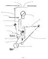
- Fig. 1 depicts a schematic depiction of a first embodiment of an indicator device in an operation readiness status.
- the indicator device comprises a lever 10 and a display device 11.
- the display device 11 is fastened at one end of the lever 10.
- the display device 11 indicates the status of the switching contacts of a circuit breaker to an operator. Therefore, symbols and/or text can be printed on the display device 11.
- the lever 10 is rotatable mounted on a pivot 12. If the lever 10 rotates, the display device 11 moves under a display window 13 of the circuit breaker and indicates other information to the operator.
- the lever 10 is coupled to a coupling element 40.
- the coupling element 40 is rotatable mounted on the circuit breaker such that if the lever 10 rotates on its pivot 12, the coupling element 40 rotates.
- the coupling element 40 comprises a crank 41 which is movable arranged in an acceptance 14 of the lever 10.
- the U-formed acceptance 14 in this embodiment is able to move the crank 41 in two directions. If the lever 10 rotates clockwise or counterclockwise, it moves also the coupling element 40 in the opposite directions.
- the lever 10 can be moved by an external trigger 7, which can be a trigger from a shunt release or an undervoltage release.
- the trigger 7 is a force which can be transferred from the shunt/undervoltage release to the lever 10 by mechanical means (not shown). If the shunt release detects an overcurrent or the undervoltage release detects an undervoltage, it triggers 7 the lever 10 to move.
- Another trigger 8 at the crank 41 moves the coupling element 40 in a position such that it also moves the lever 10 in the non-readiness position.
- the second trigger 8 comes e.g. from an electronic release, a closing mechanism or from an indicator that indicates that the circuit breaker is not correctly inserted into a framework.
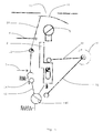
- Fig. 2 depicts the situation when the lever 10 and the coupling element 40 are moved in a second position. After the lever 10 is moved to a second position, the display element 11 indicates to the operator through the display window 13 that the circuit breaker is not ready to operate because of an external trigger.
- the coupling element 40 is further coupled to a first actuator 31 which is operative connected to an energy store 30. If the first actuator 31 is moved by the coupling element 40, the energy stored in the energy store 30 is released and the switching contacts of the circuit breaker open.
- a second actuator 32 of the energy store 30 is operative connected to a slider 2.
- the slider 2 is adapted to block or to let pass the switch-on force 6 for a latching device 5. If the slider 2 is moved to a first position according Fig. 1 , an external mechanical mechanism can switch-on a latching device 5 which closes the switching contacts of the circuit breaker by mechanical means. If the slider 2 is moved back into a second position according Fig. 2 , the switch-on force 6 cannot be transferred to the latching device 5.
- both actuators 31, 32 are moved back to the positions according Fig. 1 .
- a spring force moves the slider 2 back to the first position to enable the switch-on force 6 to switch on the circuit breaker by the latching device 5.
- the energy stored in the energy store 30 is released by other means, it cannot move the coupling device 40 into the second position according Fig. 2 because the coupling is only workable in one direction. This means that only the coupling device 40 is able to move the first actuator 31 of the energy store 30. The first actuator 31 cannot move the coupling device 40, because there is no mechanical area of contact available.
- Fig. 3 to 6 disclose a second embodiment of the invention.
- the difference between the first and the second embodiment is that the coupling element 40 is coupled to the lever 10 in a different way.
- the crank 41 is not able to move the acceptance 14' and the lever 10 to the non-readiness position because the second area of contact in the acceptance 14' is missing. Therefore, only the trigger 7 moves the lever 10 and the display element 13 to a second position which indicates now the release of a shunt or undervoltage release. It is possible to mount the embodiment of Fig. 1 and 2 and the embodiment of Fig. 3 to 6 in parallel such that the operator is informed by two display elements 13.
- Fig. 4 depicts the situation that an overcurrent or undervoltage situation triggers 7 the lever 10 to display the status that an undervoltage or overcurrent situation is detected by the overcurrent or undervoltage release.
- the energy stored in the energy store 30 is released such that the switching contacts are open.
- the slider 2 is moved into the block position such that the latching device 5 cannot be activated by the switch-on force 6 to close the switching contacts.
- Fig. 5 depicts the situation that the energy stored in the energy store 30 is released without getting a trigger 7, 8 from the external releases.
- the lever 10 and the display device 13 remains in the position no undervoltage/overcurrent release. The operator can now narrow the analysis of error.
- Fig. 6 depicts the situation that an electronic release, a closing mechanism or an indicator that indicates that the circuit breaker is not correctly inserted into a framework triggers 8 the coupling mechanism 40.
- the coupling element 40 moves the first actuator 31 to release the energy stored in the energy store 30 to open the switching contacts of the circuit breaker.
- the coupling element 40 does not move the lever 10 and the display device 13.
- the display device 13 indicates that there is no trigger 7 from an undervoltage or overcurrent release.
Landscapes
- Breakers (AREA)
- Switch Cases, Indication, And Locking (AREA)
Abstract
Description
- The invention relates to an indicator device for displaying the status of switching contacts of a circuit breaker and to a corresponding circuit breaker.
- In the state of the art circuit breaker with display devices are known. The display devices of these circuit breakers indicate the status "operative readiness" or "ok" when all requirements for operating a circuit breaker are fulfilled. These requirements are e.g. that the circuit breaker is switched off, the energy store is loaded, the circuit breaker is fully inserted in a framework, or the tripping unit is ready. If all these requirements are fulfilled, the circuit breaker is ready to operate and can be switched on. If one of the requirements is not fulfilled, the display will indicate a problem by displaying a non-operative-status. The operator does not get an indication, why the circuit breaker is not ready to operate. He has to check the circuit breaker to find the problem.
- It is therefore an object of the invention to improve the status display of a circuit breaker. This object is achieved according to the invention essentially by an indicator device according to claim 1 while the subordinate claims 2 to 8 characterize particularly advantageous refinements of the indicator device. This object is further achieved by a circuit breaker according to claim 9.
- An embodiment the present invention provides an indicator device for displaying the status of switching contacts of a circuit breaker. The circuit breaker comprises an energy store to store energy for to pass over the switching contacts from a closed position into an opened position when the energy stored in the energy store is released. Further the circuit breaker comprises a latching device for closing the switching contacts. The indicator device comprises a lever with a display element, wherein the lever is moveable between a triggered position and a non-triggered position in dependence upon at least one operational parameter. Further the indicator device comprises a coupling element which is operatively connected to the lever such that the coupling element is movable between a triggered position and a non-triggered position by the lever. The coupling element is further operatively connected to a first actuator of the energy store such that if the energy is stored in the energy store, the first actuator moves the coupling element into the non-triggered position and wherein a release of the energy stored in the energy store does not move the coupling element from the non-triggered position into the triggered position. It is therefore possible to indicate a special status to an operator. If the lever moved into the triggered position when an operational parameter triggers the lever the display element indicates the status triggered. If the stored energy is released by other circumstances like high current, the coupling element will not move the lever in the triggered position. A further display element can be used to indicate this situation.
- In a further embodiment the indicator device comprises a slider which is moved by a second actuator of the energy store into a block position to block the latching device when the stored energy is released. The circuit breaker cannot be switched on when a problem still occurs.
- In a further embodiment, the energy store is a spring-operating storage. A spring is a simple and cost-effective energy store.
- In a further embodiment the operational parameter is a trigger from a shunt release and/or from an undervoltage release. A shunt release or an undervoltage release can be assigned to the circuit breaker as an additional device. The shunt release or shunt trip triggers the circuit breaker to release the main contacts if a current above a specified level occurs. The undervoltage release triggers the circuit breaker in case of an undervoltage-situation. It is also possible that both releases (shunt and undervoltage) can be assigned together to the circuit breaker to monitor the current and voltage of the main circuits. In a further embodiment, the coupling element is triggered by an electronic release to move into the triggered position. An electronic release comprises additional electronic circuits and also monitors the current or voltage of the main circuits, but also other parameters can be monitored by an electronic release using e.g. current transformers or thermal sensors. The displayed status makes a troubleshooting easier, since the status itself is not visible from the outside of the switch, especially when displaying an undervoltage release or an operating current release.
- In a further embodiment the circuit breaker is removable arranged in a framework and the coupling element is triggered to move into the triggered position when the circuit breaker is removed from the framework. This embodiment avoids switching on a circuit breaker which is not fully inserted into the framework. If the contact plugs are not fully inserted, a sparkover between different phases can occur when the current flows.
- In a further embodiment the coupling element is triggered by a closing mechanism of the circuit breaker to move into the triggered position. A closing mechanism locks the circuit breaker so that it cannot be turned on.
- In a further embodiment the coupling element does not move the lever into the triggered position when the coupling element is triggered. The coupling element can be triggered by several inputs as described in the above mentioned embodiments. If the display element should only indicate a trigger from a shunt release or an undercurrent release, the coupling element must prevent the display element from moving into another position, if a trigger from another source (electronic release, etc.) occurs.
- The invention provides further a circuit breaker with an energy store to store energy for to pass over the switching contacts from a closed position into an opened position when the energy stored in the energy store is released and a latching device for closing the switching contacts. The circuit breaker comprises an indicator device according to any of the prescribed embodiments.
- Additional details and advantages can be gleaned from the embodiments below explained on the basis of the figures. The following is shown:
-
Fig. 1 a schematic depiction of a first embodiment of an indicator device in an operation readiness status, -
Fig. 2 a schematic depiction of a first embodiment of an indicator device in an operation not readiness status, -
Fig. 3 a schematic depiction of a second embodiment of an indicator device in a non-triggered by shunt release status, -
Fig. 4 a schematic depiction of a second embodiment of an indicator device in a triggered by shunt release status, -
Fig. 5 a schematic depiction of a second embodiment of an indicator device in a non-triggered by shunt release status, wherein the energy store was released, -
Fig. 6 a schematic depiction of a second embodiment of an indicator device in a non-triggered by shunt release status, wherein the circuit breaker was triggered by an electronic release. -
Fig. 1 depicts a schematic depiction of a first embodiment of an indicator device in an operation readiness status. The indicator device comprises alever 10 and adisplay device 11. Thedisplay device 11 is fastened at one end of thelever 10. Thedisplay device 11 indicates the status of the switching contacts of a circuit breaker to an operator. Therefore, symbols and/or text can be printed on thedisplay device 11. Thelever 10 is rotatable mounted on apivot 12. If thelever 10 rotates, thedisplay device 11 moves under adisplay window 13 of the circuit breaker and indicates other information to the operator. Thelever 10 is coupled to acoupling element 40. Thecoupling element 40 is rotatable mounted on the circuit breaker such that if thelever 10 rotates on itspivot 12, thecoupling element 40 rotates. To couple thecoupling element 40 with thelever 10, thecoupling element 40 comprises acrank 41 which is movable arranged in anacceptance 14 of thelever 10. TheU-formed acceptance 14 in this embodiment is able to move thecrank 41 in two directions. If thelever 10 rotates clockwise or counterclockwise, it moves also thecoupling element 40 in the opposite directions. - The
lever 10 can be moved by anexternal trigger 7, which can be a trigger from a shunt release or an undervoltage release. Thetrigger 7 is a force which can be transferred from the shunt/undervoltage release to thelever 10 by mechanical means (not shown). If the shunt release detects an overcurrent or the undervoltage release detects an undervoltage, it triggers 7 thelever 10 to move. - Another
trigger 8 at thecrank 41 moves thecoupling element 40 in a position such that it also moves thelever 10 in the non-readiness position. Thesecond trigger 8 comes e.g. from an electronic release, a closing mechanism or from an indicator that indicates that the circuit breaker is not correctly inserted into a framework. -
Fig. 2 depicts the situation when thelever 10 and thecoupling element 40 are moved in a second position. After thelever 10 is moved to a second position, thedisplay element 11 indicates to the operator through thedisplay window 13 that the circuit breaker is not ready to operate because of an external trigger. - The
coupling element 40 is further coupled to afirst actuator 31 which is operative connected to anenergy store 30. If thefirst actuator 31 is moved by thecoupling element 40, the energy stored in theenergy store 30 is released and the switching contacts of the circuit breaker open. Asecond actuator 32 of theenergy store 30 is operative connected to aslider 2. Theslider 2 is adapted to block or to let pass the switch-onforce 6 for alatching device 5. If theslider 2 is moved to a first position accordingFig. 1 , an external mechanical mechanism can switch-on alatching device 5 which closes the switching contacts of the circuit breaker by mechanical means. If theslider 2 is moved back into a second position accordingFig. 2 , the switch-onforce 6 cannot be transferred to thelatching device 5. It is therefore not possible to switch on the circuit breaker, if no energy is stored in theenergy store 30 and the switching contacts are open. After energy is reloaded into the energy store, bothactuators Fig. 1 . A spring force moves theslider 2 back to the first position to enable the switch-onforce 6 to switch on the circuit breaker by thelatching device 5. - If the energy stored in the
energy store 30 is released by other means, it cannot move thecoupling device 40 into the second position accordingFig. 2 because the coupling is only workable in one direction. This means that only thecoupling device 40 is able to move thefirst actuator 31 of theenergy store 30. Thefirst actuator 31 cannot move thecoupling device 40, because there is no mechanical area of contact available. -
Fig. 3 to 6 disclose a second embodiment of the invention. The difference between the first and the second embodiment is that thecoupling element 40 is coupled to thelever 10 in a different way. Thecrank 41 is not able to move the acceptance 14' and thelever 10 to the non-readiness position because the second area of contact in the acceptance 14' is missing. Therefore, only thetrigger 7 moves thelever 10 and thedisplay element 13 to a second position which indicates now the release of a shunt or undervoltage release. It is possible to mount the embodiment ofFig. 1 and2 and the embodiment ofFig. 3 to 6 in parallel such that the operator is informed by twodisplay elements 13. -
Fig. 4 depicts the situation that an overcurrent or undervoltage situation triggers 7 thelever 10 to display the status that an undervoltage or overcurrent situation is detected by the overcurrent or undervoltage release. The energy stored in theenergy store 30 is released such that the switching contacts are open. Theslider 2 is moved into the block position such that thelatching device 5 cannot be activated by the switch-onforce 6 to close the switching contacts. -
Fig. 5 depicts the situation that the energy stored in theenergy store 30 is released without getting atrigger lever 10 and thedisplay device 13 remains in the position no undervoltage/overcurrent release. The operator can now narrow the analysis of error. -
Fig. 6 depicts the situation that an electronic release, a closing mechanism or an indicator that indicates that the circuit breaker is not correctly inserted into a framework triggers 8 thecoupling mechanism 40. Thecoupling element 40 moves thefirst actuator 31 to release the energy stored in theenergy store 30 to open the switching contacts of the circuit breaker. Thecoupling element 40 does not move thelever 10 and thedisplay device 13. Thedisplay device 13 indicates that there is notrigger 7 from an undervoltage or overcurrent release. -
- 10
- lever
- 11
- display element
- 12
- pivot
- 13
- display window
- 14, 14'
- acceptance
- 2
- slider
- 30
- energy store
- 31
- first actuator
- 32
- second actuator
- 40
- coupling element
- 41
- crank
- 5
- latching device
- 6
- switch-on force
- 7
- trigger (operational parameter)
- 8
- trigger (electronic release, closing mechanism)
Claims (9)
- An indicator device for displaying the status of switching contacts of a circuit breaker, the circuit breaker comprising an energy store (30) to store energy for to pass over the switching contacts from a closed position into an opened position when the energy stored in the energy store (30) is released, a latching device (5) for closing the switching contacts,
the indicator device comprising- a lever (10) with a display element (11), wherein the lever (10) is movable between a triggered position and a non-triggered position in dependence upon at least one operational parameter (7), and- a coupling element (40) which is operatively connected to the lever (10) such that the coupling element (40) is movable between a triggered position and a non-triggered position by the lever (10), wherein the coupling element (40) is further operatively connected to a first actuator (31) of the energy store (30) such that if the energy is stored in the energy store (30), the first actuator (31) moves the coupling element (40) into the non-triggered position and wherein a release of the energy stored in the energy store (30) does not move the coupling element (40) from the non-triggered position into the triggered position. - The indicator device according to claim 1, wherein the indicator device further comprises a slider (2) which is moved by a second actuator (32) of the energy store (30) into a block position to block the latching device (5) when the energy stored in the energy store (30) is released.
- The indicator device according to any of the preceding claims, wherein the energy store (30) is a spring-operating storage.
- The indicator device according to any of the preceding claims, wherein the operational parameter (7) is a trigger from a shunt release and/or from an undervoltage release.
- The indicator device according to any of the preceding claims, wherein the coupling element (40) is triggered (8) by an electronic release to move into the triggered position.
- The indicator device according to any of the preceding claims, wherein the circuit breaker is removable arranged in a framework and the coupling element (40) is triggered (8) to move into the triggered position when the circuit breaker is removed from the framework.
- The indicator device according to any of the preceding claims, wherein the coupling element (40) is triggered (8) by a closing mechanism of the circuit breaker to move into the triggered position.
- The indicator device according to any of the claims 5-7, wherein the coupling element (40) does not move the lever (10) into the triggered position when the coupling element (40) is triggered (8).
- A circuit breaker with an energy store (30) to store energy for to pass over the switching contacts from a closed position into an opened position when the energy stored in the energy store (30) is released and a latching device for closing the switching contacts, comprising an indicator device according to any of the preceding claims.
Priority Applications (3)
| Application Number | Priority Date | Filing Date | Title |
|---|---|---|---|
| EP20100175979 EP2428973A1 (en) | 2010-09-09 | 2010-09-09 | Indicator device of a circuit breaker |
| CN2011102596716A CN102403168A (en) | 2010-09-09 | 2011-08-30 | Indicator device of a circuit breaker |
| US13/227,503 US8624145B2 (en) | 2010-09-09 | 2011-09-08 | Indicator device of a circuit breaker |
Applications Claiming Priority (1)
| Application Number | Priority Date | Filing Date | Title |
|---|---|---|---|
| EP20100175979 EP2428973A1 (en) | 2010-09-09 | 2010-09-09 | Indicator device of a circuit breaker |
Publications (1)
| Publication Number | Publication Date |
|---|---|
| EP2428973A1 true EP2428973A1 (en) | 2012-03-14 |
Family
ID=43530296
Family Applications (1)
| Application Number | Title | Priority Date | Filing Date |
|---|---|---|---|
| EP20100175979 Withdrawn EP2428973A1 (en) | 2010-09-09 | 2010-09-09 | Indicator device of a circuit breaker |
Country Status (3)
| Country | Link |
|---|---|
| US (1) | US8624145B2 (en) |
| EP (1) | EP2428973A1 (en) |
| CN (1) | CN102403168A (en) |
Cited By (3)
| Publication number | Priority date | Publication date | Assignee | Title |
|---|---|---|---|---|
| DE102016125422A1 (en) | 2016-12-22 | 2018-06-28 | Eaton Electrical Ip Gmbh & Co. Kg | Tripping device for a switching device and switching device with such a triggering device |
| EP3319102A4 (en) * | 2015-06-30 | 2019-02-27 | Seari Electric Technology Co., Ltd. | ELECTRICAL SWITCHING INDICATION DEVICE |
| CN115424881A (en) * | 2022-09-16 | 2022-12-02 | 重庆德普电气有限公司 | Closing indication device and isolating switch |
Families Citing this family (3)
| Publication number | Priority date | Publication date | Assignee | Title |
|---|---|---|---|---|
| CN111584311B (en) * | 2019-05-21 | 2022-07-08 | 杭州德睿达电气有限公司 | Divide-shut display device of direct current quick circuit breaker |
| CN116959928B (en) * | 2023-08-29 | 2024-03-05 | 泰安市泰和电力设备有限公司 | Energy storage switching indicating device of circuit breaker spring operating mechanism and identification method |
| EP4560672A1 (en) * | 2023-11-23 | 2025-05-28 | Xiamen Hongfa Electrical Safety & Controls Co., Ltd. | Indication device for stored-energy electric operating mechanism of circuit breaker, and circuit breaker |
Citations (4)
| Publication number | Priority date | Publication date | Assignee | Title |
|---|---|---|---|---|
| US4166989A (en) * | 1978-04-19 | 1979-09-04 | General Electric Company | Circuit breaker remote close and charged signalling apparatus |
| US4301342A (en) * | 1980-06-23 | 1981-11-17 | General Electric Company | Circuit breaker condition indicator apparatus |
| US6130390A (en) * | 1997-06-19 | 2000-10-10 | General Electric Company | Contact position indicator for an industrial-rated circuit breaker |
| US20020079207A1 (en) * | 2000-12-27 | 2002-06-27 | Greenberg Randall Lee | Handle position indicator |
Family Cites Families (6)
| Publication number | Priority date | Publication date | Assignee | Title |
|---|---|---|---|---|
| US4128750A (en) * | 1978-02-27 | 1978-12-05 | General Electric Company | Circuit breaker closure control and condition indicator apparatus |
| US4351994A (en) * | 1980-04-01 | 1982-09-28 | S&C Electric Company | High-voltage switchgear |
| US4301433A (en) * | 1980-06-23 | 1981-11-17 | General Electric Company | Circuit breaker electrical closure control apparatus |
| US6005208A (en) * | 1998-03-03 | 1999-12-21 | General Electric Company | Industrial draw-out circuit breaker electrical connection indication |
| US7906740B2 (en) * | 2008-04-15 | 2011-03-15 | General Electric Company | Readiness for closing indicator for circuit breakers |
| DE102010036222B4 (en) * | 2010-08-30 | 2023-08-17 | Siemens Aktiengesellschaft | Arrangement with an electric switch |
-
2010
- 2010-09-09 EP EP20100175979 patent/EP2428973A1/en not_active Withdrawn
-
2011
- 2011-08-30 CN CN2011102596716A patent/CN102403168A/en active Pending
- 2011-09-08 US US13/227,503 patent/US8624145B2/en not_active Expired - Fee Related
Patent Citations (4)
| Publication number | Priority date | Publication date | Assignee | Title |
|---|---|---|---|---|
| US4166989A (en) * | 1978-04-19 | 1979-09-04 | General Electric Company | Circuit breaker remote close and charged signalling apparatus |
| US4301342A (en) * | 1980-06-23 | 1981-11-17 | General Electric Company | Circuit breaker condition indicator apparatus |
| US6130390A (en) * | 1997-06-19 | 2000-10-10 | General Electric Company | Contact position indicator for an industrial-rated circuit breaker |
| US20020079207A1 (en) * | 2000-12-27 | 2002-06-27 | Greenberg Randall Lee | Handle position indicator |
Cited By (3)
| Publication number | Priority date | Publication date | Assignee | Title |
|---|---|---|---|---|
| EP3319102A4 (en) * | 2015-06-30 | 2019-02-27 | Seari Electric Technology Co., Ltd. | ELECTRICAL SWITCHING INDICATION DEVICE |
| DE102016125422A1 (en) | 2016-12-22 | 2018-06-28 | Eaton Electrical Ip Gmbh & Co. Kg | Tripping device for a switching device and switching device with such a triggering device |
| CN115424881A (en) * | 2022-09-16 | 2022-12-02 | 重庆德普电气有限公司 | Closing indication device and isolating switch |
Also Published As
| Publication number | Publication date |
|---|---|
| US20120061224A1 (en) | 2012-03-15 |
| CN102403168A (en) | 2012-04-04 |
| US8624145B2 (en) | 2014-01-07 |
Similar Documents
| Publication | Publication Date | Title |
|---|---|---|
| KR101620298B1 (en) | Remote operated circuit breaker with manual reset | |
| US8624145B2 (en) | Indicator device of a circuit breaker | |
| JP5108122B2 (en) | Circuit breaker | |
| CN103824735B (en) | For the thermal-magnetic trip device for making multi-phase circuit breaker trip | |
| US9928977B2 (en) | Electrical switching apparatus, and operating handle assembly and trip cam therefor | |
| JP6072065B2 (en) | TRIP MECHANISM AND ELECTRICAL SWITCHING EQUIPMENT INCLUDING TRIP MEMBER PRESSED BY PRESSURE RESULTING FROM AN ARC IN AN ARC Chamber | |
| CN101562096B (en) | Readiness for closing indicator for circuit breakers | |
| CN101329969A (en) | Circuit breaker for wiring with leakage alarm function | |
| US7583170B2 (en) | Switching device with switch latch | |
| EP2242078B1 (en) | Mechanism or resettable trip indicator mechanism for a circuit interrupter and circuit interrupter including the same | |
| US20120048695A1 (en) | Arrangement Comprising An Electrical Switch | |
| CN102804321B (en) | For the switch element of the protection switch with rocking arm | |
| US8907751B2 (en) | Power circuit breaker | |
| EP3319102B1 (en) | Indication device of electric switch | |
| CN101617380B (en) | switchgear with knob | |
| US8993912B2 (en) | Switching apparatus | |
| CN103999184B (en) | Transmission component | |
| US9111695B2 (en) | Electrical switching device, especially circuit breaker | |
| CN105810520B (en) | The method and breaker of operating breaker | |
| JP2014072178A (en) | Leakage breaker with poor connection cut-off function | |
| US20060132270A1 (en) | Double-lever mechanism, trip actuator assembly and electrical switching apparatus employing the same | |
| EP3048632A1 (en) | Method for operating a circuit breaker and circuit breaker |
Legal Events
| Date | Code | Title | Description |
|---|---|---|---|
| AK | Designated contracting states |
Kind code of ref document: A1 Designated state(s): AL AT BE BG CH CY CZ DE DK EE ES FI FR GB GR HR HU IE IS IT LI LT LU LV MC MK MT NL NO PL PT RO SE SI SK SM TR |
|
| AX | Request for extension of the european patent |
Extension state: BA ME RS |
|
| PUAI | Public reference made under article 153(3) epc to a published international application that has entered the european phase |
Free format text: ORIGINAL CODE: 0009012 |
|
| 17P | Request for examination filed |
Effective date: 20120914 |
|
| RAP1 | Party data changed (applicant data changed or rights of an application transferred) |
Owner name: EATON ELECTRICAL IP GMBH & CO. KG |
|
| GRAP | Despatch of communication of intention to grant a patent |
Free format text: ORIGINAL CODE: EPIDOSNIGR1 |
|
| INTG | Intention to grant announced |
Effective date: 20150515 |
|
| STAA | Information on the status of an ep patent application or granted ep patent |
Free format text: STATUS: THE APPLICATION IS DEEMED TO BE WITHDRAWN |
|
| 18D | Application deemed to be withdrawn |
Effective date: 20150926 |