EP2428396A1 - Verfahren zur Herstellung eines Rückenlehnenrahmenelements - Google Patents
Verfahren zur Herstellung eines Rückenlehnenrahmenelements Download PDFInfo
- Publication number
- EP2428396A1 EP2428396A1 EP11180662A EP11180662A EP2428396A1 EP 2428396 A1 EP2428396 A1 EP 2428396A1 EP 11180662 A EP11180662 A EP 11180662A EP 11180662 A EP11180662 A EP 11180662A EP 2428396 A1 EP2428396 A1 EP 2428396A1
- Authority
- EP
- European Patent Office
- Prior art keywords
- profile
- axis
- backrest frame
- frame element
- connecting element
- Prior art date
- Legal status (The legal status is an assumption and is not a legal conclusion. Google has not performed a legal analysis and makes no representation as to the accuracy of the status listed.)
- Granted
Links
Images


Classifications
-
- B—PERFORMING OPERATIONS; TRANSPORTING
- B60—VEHICLES IN GENERAL
- B60N—SEATS SPECIALLY ADAPTED FOR VEHICLES; VEHICLE PASSENGER ACCOMMODATION NOT OTHERWISE PROVIDED FOR
- B60N2/00—Seats specially adapted for vehicles; Arrangement or mounting of seats in vehicles
- B60N2/68—Seat frames
- B60N2/686—Panel like structures
-
- B—PERFORMING OPERATIONS; TRANSPORTING
- B60—VEHICLES IN GENERAL
- B60N—SEATS SPECIALLY ADAPTED FOR VEHICLES; VEHICLE PASSENGER ACCOMMODATION NOT OTHERWISE PROVIDED FOR
- B60N2/00—Seats specially adapted for vehicles; Arrangement or mounting of seats in vehicles
- B60N2/68—Seat frames
-
- B—PERFORMING OPERATIONS; TRANSPORTING
- B60—VEHICLES IN GENERAL
- B60N—SEATS SPECIALLY ADAPTED FOR VEHICLES; VEHICLE PASSENGER ACCOMMODATION NOT OTHERWISE PROVIDED FOR
- B60N2/00—Seats specially adapted for vehicles; Arrangement or mounting of seats in vehicles
- B60N2/68—Seat frames
- B60N2/682—Joining means
Definitions
- the invention relates to a method for producing a backrest frame element, a method for producing a backrest frame and a backrest frame.
- backrest frames for vehicle seats which serve to support a padding of the backrest.
- the backrest frame is usually made of a metal and in particular of a plurality of pressed sheet metal parts and gives a backrest of the vehicle seat the necessary mechanical stability.
- the backrest of the vehicle seat must be able to withstand high acceleration forces in order to ensure the safety of a vehicle occupant located on the vehicle seat.
- the sheet metal stampings are usually manner to form the backrest frame together positively, positively and / or materially connected and in particular welded.
- a backrest for a motor vehicle seat in which a backrest frame has an edge which is composed of sections that merge into one another.
- the rim is substantially U-shaped and includes a top edge, right and left corner edges, and right and left side edges.
- Object of the present invention is to provide an improved and automatable method for producing a seat back frame element, are saved in the manufacturing costs, without the mechanical stability of the To affect back element frame member having backrest frame.
- the object is achieved with a method for producing a seat back frame element with the features of claim 1, a method for producing a seat back frame with the features of claim 6 and a seat back frame for a vehicle seat with the features of claim 8.
- a substantially U-shaped seat back frame member for a vehicle seat includes a first side member, a second side member, and a lower link connecting the first and second side members.
- a sheet metal blank is formed into a first profile part.
- the first profile part comprises a first partial profile corresponding to the first lateral element and a second partial profile corresponding to the second lateral element.
- the first profile part is cut out.
- the first part profile is bent around a first axis and the second part profile around a second axis to a second profile part.
- the second profile part is formed into the backrest frame element, in which the lower connection element is formed.
- the structurally complex backrest frame element can be produced in one piece by means of a forming process.
- the one-piece manufactured The backrest frame member thus has an increased strength and mechanical stability, while eliminating manufacturing steps in the production, which are necessary in a production of the backrest frame member of a plurality of sections. Thus, manufacturing and assembly costs are saved.
- the sheet metal blank and / or the second profile part is or are formed in a deep-drawing process.
- Deep-drawing processes are easy to automate and are therefore particularly suitable for the economic production of mass products, such as backrest frames.
- the first part profile is bent by about 90 degrees about the first axis.
- the second part profile is bent about 90 degrees about the second axis. The bending of the sub-profiles allows a structuring of the molded backrest frame member in two mutually orthogonal planes and thus the production of the backrest frame member from a single piece.
- substantially the first axis, the second axis, the first side member and the second side member are parallel to each other.
- the first and second side elements each extend essentially in planes arranged parallel to one another. This advantageously provides a mechanically particularly stable structure for the back frame element.
- the first axis and the second axis are spaced apart. A distance between the first and the second axis corresponds to a width of the lower connecting element.
- an upper connecting element is positively, positively and / or materially connected to the backrest frame element.
- the peripheral, closed backrest frame produced in this way consists essentially only of two separate components, the essentially U-shaped backrest frame element and the web-like upper connecting element and can therefore be produced quickly and cost-efficiently.
- the upper connecting element is connected to the backrest frame element by means of a plurality of welding points or welds.
- a thus manufactured seat back frame for a vehicle seat has a U-shaped and one-piece seat back frame member with increased strength.
- a rear impact of the vehicle occupant located on the vehicle seat is particularly protected by the stable backrest of the vehicle seat and reduces the risk of injury.
- FIG. 1 shows a perspective view of the substantially U-shaped backrest frame member 1, comprising a first side member 1.1, a second side member 1.2 and a lower connecting element arranged therebetween 1.3.
- the first and second side members 1.1, 1.2 are oppositely disposed and each substantially extend in a respective plane that is parallel to an xz plane.
- the xz plane is spanned by an x-axis X and a z-axis Z orthogonal thereto.
- the arranged between the first and second side member 1.1, 1.2 lower connecting element 1.3 has a width B and extends substantially parallel to a yz plane which is spanned by a y-axis Y and the z-axis Z.
- the lower connecting element 1.3 is arranged substantially perpendicular to the first side member 1.1 and the second side member 1.2.
- the x-axis X is typically parallel to the direction of travel
- the y-axis Y is typically parallel to a pitch axis
- the z-axis Z is typically parallel to a vertical axis of the vehicle
- the first side element 1.1, the second side element 1.2 and the lower connection element 1.3 may have material recesses 1.4 for weight reduction.
- the material recesses serve 1.4 of the attachment of additional components, such as the suspension of spring elements of a lumbar support or the mounting of an adjusting lever or a Verstellgestfites for the lumbar support.
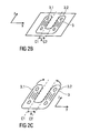
- FIGS. 2A to 2D schematically illustrate a method of manufacturing the seat back frame member 1.
- FIGS. 2A and 2 B schematically show a first step of the method according to the invention.
- a sheet metal blank 2 also called a blank, is formed in a press by means of a deep-drawing process into a first profile part 3.
- the sheet metal blank 2 can be pressed by the punch through the drawing ring for shaping the sheet metal blank 2.
- the first profile part 3 has a first partial profile 3.1 corresponding to the first lateral element 1.1 and a second partial profile 3.2 corresponding to the second lateral element 1.2.
- the first part profile 3.1 and the second part profile 3.2 are spaced apart, wherein a distance A of the width B of the lower connecting element 1.3 corresponds.
- substantially the structure of the first and second side element 1.1, 1.2 are formed, wherein the structure of the lower connecting element 1.3 substantially in one subsequent process step is formed by means of a further deformation.
- the substantially planar and U-shaped first profile part 3 is cut out in a second method step.
- the first and second side elements 1.1, 1.2 oriented parallel to the xz plane are formed.
- FIG. 2D schematically shows the second profile part 4 with the already correctly trained and aligned first and second side elements 1.1, 1.2.
- the second profile part 4 is formed into a U-shaped backrest frame element 1 by means of a deep-drawing process and completed.
- the lower connecting element 1.3 is formed in a lying between the first and second side member 1.1, 1.2 intermediate region 4.1.
- the first axis C1 and the second axis C2 are parallel to each other and parallel to the z-axis Z
- Figure 4 shows a circumferential backrest frame 5, which comprises the one-piece and U-shaped profilelehenrahmenelement 1 and an upper connecting element 5.1.
- the upper connecting element 5.1 is integrally connected to the first and second side element 1.1, 1.2 of the counsellehenrahmenelement 1 by means of a welded joint.
- the upper connecting element 5.1 can be connected by means of a non-positive and / or positive connection, for example by means of rivets.
- the upper connecting element 5.1 is welded to the first and second side element 1.1, 1.2 of the backrest frame element 1.
- a plurality of welds or welds is formed.
Landscapes
- Engineering & Computer Science (AREA)
- Aviation & Aerospace Engineering (AREA)
- Transportation (AREA)
- Mechanical Engineering (AREA)
- Seats For Vehicles (AREA)
- Chair Legs, Seat Parts, And Backrests (AREA)
Abstract
Description
- Die Erfindung betrifft ein Verfahren zur Herstellung eines Rückenlehnenrahmenelements, ein Verfahren zur Herstellung eines Rückenlehnenrahmens und einen Rückenlehnenrahmen.
- Aus dem Stand der Technik sind allgemein Rückenlehnenrahmen für Fahrzeugsitze bekannt, die dazu dienen, eine Polsterung der Rückenlehne zu tragen. Der Rückenlehnenrahmen ist üblicher Weise aus einem Metall und insbesondere aus einer Mehrzahl von Blechpressteilen gefertigt und gibt einer Rückenlehne des Fahrzeugsitzes die notwendige mechanische Stabilität. Insbesondere bei einem Unfall des Fahrzeugs muss die Rückenlehne des Fahrzeugsitzes hohen Beschleunigungskräften Stand halten können, um die Sicherheit eines auf dem Fahrzeugsitz befindlichen Fahrzeuginsassen sicherstellen zu können. Die Blechpressteile sind üblicher Weise zur Bildung des Rückenlehnenrahmens miteinander kraft-, form- und/oder stoffschlüssig verbunden und insbesondere verschweißt.
- Aus der
DE 100 42 850 A1 ist eine Rückenlehne für einen Kraftfahrzeugsitz bekannt, bei dem ein Rückenlehnenrahmen einen Rand aufweist, der aus ineinander übergehenden Teilstücken zusammengesetzt ist. Der Rand ist im Wesentlichen U-förmig ausgebildet und umfasst einen Toprand, einen rechten und einen linken Eckrand und einen rechten und linken Seitenrand. - Aufgabe der vorliegenden Erfindung ist es, ein verbessertes und automatisierbares Verfahren zur Herstellung eines Rückenlehnenrahmenelements anzugeben, bei dem Herstellungskosten eingespart sind, ohne die mechanische Stabilität eines das Rückenelementrahmenelement aufweisenden Rückenlehnenrahmens zu beeinträchtigen.
- Die Aufgabe wird erfindungsgemäß mit einem Verfahren zur Herstellung eines Rückenlehnenrahmenelements mit den Merkmalen des Patentanspruchs 1, einem Verfahren zur Herstellung eines Rückenlehnenrahmens mit den Merkmalen des Patentanspruchs 6 und einem Rückenlehnenrahmen für einen Fahrzeugsitz mit den Merkmalen des Patentanspruchs 8 gelöst.
- Vorteilhafte Ausgestaltungen der Erfindung sind Gegenstand der Unteransprüche.
- Ein im Wesentlichen U-förmiges Rückenlehnenrahmenelement für einen Fahrzeugsitz umfasst ein erstes Seitenelement, ein zweites Seitenelement und ein das erste und zweite Seitenelement verbindendes unteres Verbindungselement. Erfindungsgemäß wird bei einem Verfahren zur Herstellung des Rückenlehnenrahmenelements, in einem ersten Verfahrensschritt, ein Blechzuschnitt zu einem ersten Profilteil umgeformt. Das erste Profilteil umfasst ein zu dem ersten Seitenelement korrespondierendes erstes Teilprofil und ein zu dem zweiten Seitenelement korrespondierendes zweites Teilprofil. In einem zweiten Verfahrensschritt wird das erste Profilteil ausgeschnitten. In einem dritten Verfahrensschritt werden das erste Teilprofil um eine erste Achse und das zweites Teilprofil um eine zweite Achse zu einem zweiten Profilteil umgebogen. In einem vierten Verfahrensschritt wird das zweite Profilteil zum Rückenlehnenrahmenelement umgeformt, in dem das untere Verbindungselement geformt wird.
- Mit dem erfindungsgemäßen Verfahren ist erreicht, dass das strukturell komplexe Rückenlehnenrahmenelement mittels eines Umformverfahrens aus einem Stück herstellbar ist. Das hergestellte einstückige Rücklehnenrahmenelement weist somit eine erhöhte Festigkeit und mechanische Stabilität auf, wobei gleichzeitig Fertigungsschritte bei der Herstellung entfallen, die bei einer Herstellung des Rückenlehnenrahmenelements aus einer Vielzahl von Teilstücken notwendig sind. Somit sind Herstellungs- und Montagekosten eingespart.
- Vorzugsweise wird bzw. werden der Blechzuschnitt und/oder das zweite Profilteil in einem Tiefziehverfahren umgeformt. Tiefziehverfahren sind leicht automatisierbar und sind somit zur wirtschaftlichen Fertigung von Massenprodukten, wie Rückenlehnenrahmen, besonders geeignet.
- Einer bevorzugten Ausgestaltung der Erfindung zufolge wird das erste Teilprofil um etwa 90 Grad um die erste Achse umgebogen. Das zweite Teilprofil wird um etwa 90 Grad um die zweite Achse umgebogen. Das Umbiegen der Teilprofile ermöglicht eine Strukturierung des zu formenden Rückenlehnenrahmenelements in zwei zueinander orthogonalen Ebenen und damit die Herstellung des Rückenlehnenrahmenelements aus einem einzigen Stück.
- Vorzugsweise verlaufen im Wesentlichen die erste Achse, die zweite Achse, das erste Seitenelement und das zweite Seitenelement parallel zueinander. Nach dem Umbiegen des ersten und des zweiten Seitenelements um die jeweilige erste oder zweite Achse verlaufen das erste und das zweite Seitenelement jeweils im Wesentlichen in zueinander parallel angeordneten Ebenen. Damit ist vorteilhafter Weise eine mechanisch besonders stabile Struktur für das Rückenrahmenelement gegeben.
- Die erste Achse und die zweite Achse sind voneinander beabstandet. Ein Abstand zwischen der ersten und der zweiten Achse entspricht einer Breite des unteren Verbindungselements. Nach dem Umbiegen des ersten und des zweiten Seitenelements kann somit in dem das erste und zweite Seitenelement verbindenden Bereich das Verbindungselement in dem vierten Verfahrensschritt geformt werden.
- Bei einem Verfahren zur Herstellung eines Rückenlehnenrahmens für einen Fahrzeugsitz wird ein oberes Verbindungselement mit dem Rückenlehnenrahmenelement form-, kraft- und/oder stoffschlüssig verbunden. Der so gefertigte umlaufende, geschlossene Rückenlehnenrahmen besteht im Wesentlichen nur aus zwei separaten Bauteilen, dem im Wesentlichen U-förmigen Rückenlehnenrahmenelement und dem stegartigen oberen Verbindungselement und kann daher schnell und kosteneffizient hergestellt werden.
- Einer bevorzugten Ausbildung der Erfindung zufolge wird das obere Verbindungselement mittels einer Mehrzahl von Schweißpunkten oder Schweißnähten mit dem Rückenlehnenrahmenelement verbunden.
- Ein so hergestellter Rückenlehnenrahmen für einen Fahrzeugsitz weist ein U-förmiges und einstückiges Rückenlehnenrahmenelement mit erhöhter Festigkeit auf. Insbesondere bei einem Heckaufprall ist der auf dem Fahrzeugsitz befindliche Fahrzeuginsasse durch die stabile Rückenlehne des Fahrzeugsitzes besonders geschützt und eine Verletzungsgefahr verringert.
- Anhand der beigefügten schematischen Figuren wird die Erfindung näher erläutert.
- Dabei zeigen:
- Figur 1
- eine perspektivische Darstellung eines Rückenlehnenrahmenelements,
- Figur 2A bis 2D
- schematisch ein Verfahren zur Herstellung eines Rückenlehnenrahmenelements,
- Figur 3
- eine perspektivische Darstellung des Rückenlehnenrahmens.
- Einander entsprechende Teile sind in allen Figuren mit den gleichen Bezugszeichen versehen.
-
Figur 1 zeigt eine perspektivische Darstellung des im Wesentlichen U-förmigen Rückenlehnenrahmenelements 1, das ein erstes Seitenelement 1.1, ein zweites Seitenelement 1.2 und ein dazwischen angeordnetes unteres Verbindungselement 1.3 umfasst. Das erste und das zweite Seitenelement 1.1, 1.2 sind gegenüberliegend angeordnet und verlaufen jeweils im Wesentlichen in einer jeweiligen Ebene, die parallel zu einer xz-Ebene verläuft. Die xz-Ebene ist von einer x-Achse X und einer dazu orthogonalen z-Achse Z aufgespannt. - Das zwischen erstem und zweitem Seitenelement 1.1, 1.2 angeordnete untere Verbindungselement 1.3 weist eine Breite B auf und verläuft im Wesentlichen parallel zu einer yz-Ebene, die von einer y-Achse Y und der z-Achse Z aufgespannt ist. Somit ist das untere Verbindungselement 1.3 im Wesentlichen senkrecht zum ersten Seitenelement 1.1 und zum zweiten Seitenelement 1.2 angeordnet.
- Insbesondere bei einer Installation des Rückenlehnenrahmenelements 1 in einer Rückenlehne eines Fahrzeugsitzes ist die x-Achse X typischer Weise parallel zur Fahrtrichtung, die y-Achse Y typischer Weise parallel zu einer Nickachse und die z-Achse Z typischer Weise parallel zu einer Hochachse des Fahrzeugs ausgerichtet.
- Das erste Seitenelement 1.1, das zweite Seitenelement 1.2 und das untere Verbindungselement 1.3 können Materialaussparungen 1.4 zur Gewichtsreduktion aufweisen.
- Alternativ oder zusätzlich dazu dienen die Materialaussparungen 1.4 der Befestigung von zusätzlichen Bauteilen, wie beispielsweise dem Einhängen von Federelementen einer Lordosenstütze oder dem Montieren eines Verstellhebels bzw. eines Verstellgestänges für die Lordosenstütze.
-
Figuren 2A bis 2D illustrieren schematisch ein Verfahren zur Herstellung des Rückenlehnenrahmenelements 1. -
Figuren 2A und2B zeigen schematisch einen ersten Verfahrensschritt des erfindungsgemäßen Verfahrens. Ein auch Platine genannter Blechzuschnitt 2 wird in einer Presse mittels eines Tiefziehverfahrens zu einem ersten Profilteil 3 umgeformt. - Dabei können typischer Weise Formwerkzeuge, wie Stempel und Ziehring, zum Einsatz kommen. Insbesondere kann in der Presse der Blechzuschnitt 2 von dem Stempel durch den Ziehring zur Formgebung des Blechzuschnitts 2 hindurchgedrückt werden.
- Das erste Profilteil 3 weist ein zum ersten Seitenelement 1.1 korrespondierendes erstes Teilprofil 3.1 und ein zum zweiten Seitenelement 1.2 korrespondierendes zweites Teilprofil 3.2 auf. Dabei sind das erstes Teilprofil 3.1 und das zweites Teilprofil 3.2 voneinander beabstandet, wobei ein Abstand A der Breite B des unteren Verbindungselements 1.3 entspricht. Im ersten Verfahrensschritt werden im Wesentlichen die Struktur des ersten und zweiten Seitenelements 1.1, 1.2 geformt, wobei die Struktur des unteren Verbindungselements 1.3 im Wesentlichen in einem nachfolgendem Verfahrensschritt mittels einer weiteren Umformung geformt wird.
- Das im Wesentlichen plane und U-förmige erste Profilteil 3 wird in einem zweiten Verfahrensschritt ausgeschnitten.
- Anschließend wird in einem in
Figur 2C gezeigten dritten Verfahrensschritt das erste Teilprofil 3.1 um eine erste Achse C1 und das zweite Teilprofil 3.2 um eine zweite Achse C2 zur Bildung eines zweiten Profilteils 4 um jeweils etwa 90 Grad umgebogen, wie von den Pfeilen inFigur 2C angedeutet. Dabei werden die parallel zur xz-Ebene ausgerichteten ersten und zweiten Seitenelemente 1.1, 1.2 geformt. -
Figur 2D zeigt schematisch das zweite Profilteil 4 mit den bereits korrekt ausgebildeten und ausgerichteten ersten und zweiten Seitenelementen 1.1, 1.2. In einem vierten Verfahrensschritt 4 wird das zweite Profilteil 4 zum U-förmigen Rückenlehnenrahmenelement 1 mittels eines Tiefziehverfahrens umgeformt und fertig gestellt. Dabei wird das untere Verbindungselement 1.3 in einem zwischen ersten und zweiten Seitenelement 1.1, 1.2 liegenden Zwischenbereich 4.1 geformt. Die erste Achse C1 und die zweite Achse C2 verlaufen parallel zueinander und parallel zur z-Achse Z - Figur 4 zeigt einen umlaufenden Rückenlehnenrahmen 5, der das einstückige und U-förmige Rückenlehenrahmenelement 1 und ein oberes Verbindungselement 5.1 umfasst. Das obere Verbindungselement 5.1 ist mit dem ersten und zweiten Seitenelement 1.1, 1.2 des Rückenlehenrahmenelement 1 mittels einer Schweißverbindung stoffschlüssig verbunden.
- Alternativ dazu kann das obere Verbindungselement 5.1 mittels einer kraft- und/oder formschlüssigen Verbindung, beispielsweise mittels Nieten, verbunden sein.
- Zur Herstellung eines Rückenlehnenrahmens 5 wird das obere Verbindungselement 5.1 mit dem ersten und zweiten Seitenelement 1.1, 1.2 des Rückenlehnenrahmenelements 1 verschweißt. Zur stoffschlüssigen Verbindung von oberen Verbindungselement 5.1 und Rückenlehnenrahmenelement 1 wird eine Mehrzahl von Schweißpunkten oder Schweißnähten gebildet.
-
- 1
- Rückenlehnenrahmenelement
- 1.1
- erstes Seitenelement
- 1.2
- zweites Seitenelement
- 1.3
- unteres Verbindungselement
- 1.4
- Materialaussparungen
- 2
- Blechzuschnitt
- 3
- erstes Profilteil
- 3.1
- erstes Teilprofil
- 3.2
- zweites Teilprofil
- 4
- zweites Profilteil
- 4.1
- Zwischenbereich
- 5
- Rückenlehnenrahmen
- 5.1
- oberes Verbindungselement
- X
- x-Achse
- Y
- y-Achse
- Z
- z-Achse
- A
- Abstand
- B
- Breite des unteren Verbindungselements
- C1
- erste Achse
- C2
- zweite Achse
Claims (8)
- Verfahren zur Herstellung eines im Wesentlichen U-förmigen Rückenlehnenrahmenelements (1) für einen Fahrzeugsitz, welches ein erstes Seitenelement (1.1), ein zweites Seitenelement (1.2) und ein diese verbindendes unteres Verbindungselement (1.3) umfasst, dadurch gekennzeichnet, dass in einem ersten Verfahrensschritt ein Blechzuschnitt (2) zu einem ersten Profilteil (3) umgeformt wird, welches ein zu dem ersten Seitenelement (1.1) korrespondierendes erstes Teilprofil (3.1) und ein zu dem zweiten Seitenelement (1.2) korrespondierendes zweites Teilprofil (3.2) umfasst, in einem zweiten Verfahrensschritt das erste Profilteil (3) ausgeschnitten wird, in einem dritten Verfahrensschritt das erste Teilprofil (3.1) um eine erste Achse (C1) und das zweite Teilprofil (3.2) um eine zweite Achse (C2) zu einem zweiten Profilteil (4) umgebogen werden und in einem vierten Verfahrensschritt das zweite Profilteil (4) zum Rückenlehnenrahmenelement (1) umgeformt wird, in dem das untere Verbindungselement (1.3) geformt wird.
- Verfahren nach Anspruch 1,
dadurch gekennzeichnet, dass der Blechzuschnitt (2) und/oder das zweite Profilteil (4) in einem Tiefziehverfahren umgeformt werden bzw. wird. - Verfahren nach Anspruch 1 oder 2,
dadurch gekennzeichnet, dass das erste Teilprofil (3.1) um etwa 90 Grad um die erste Achse (C1) umgebogen wird und das zweite Teilprofil (3.2) um etwa 90 Grad um die zweite Achse (C2) umgebogen wird. - Verfahren nach einem der vorherigen Ansprüchen,
dadurch gekennzeichnet, dass im Wesentlichen die erste Achse (C1), die zweite Achse (C2), das erste Seitenelement (1.1) und das zweite Seitenelement (1.2) parallel zueinander verlaufen. - Verfahren nach einem der vorherigen Ansprüchen,
dadurch gekennzeichnet, dass die erste Achse (C1) und die zweite Achse (C2) voneinander beabstandet sind und ein Abstand (A) zwischen der ersten und der zweiten Achse (C1, C2) einer Breite (B) des unteren Verbindungselements (1.3) entspricht. - Verfahren zur Herstellung eines Rückenlehnenrahmens (5) für einen Fahrzeugsitz,
dadurch gekennzeichnet, dass ein oberes Verbindungselement (5.1) mit einem mittels eines Verfahrens nach einem der Ansprüche 1 bis 5 hergestellten Rückenlehnenrahmenelement (1) form-, kraft- und/oder stoffschlüssig verbunden wird. - Verfahren nach Anspruch 6,
dadurch gekennzeichnet, dass das obere Verbindungselement (5.1) mittels einer Mehrzahl von Schweißpunkten oder Schweißnähten mit dem Rückenlehnenrahmenelement (1) verbunden wird. - Rückenlehnenrahmen (5) für einen Fahrzeugsitz, hergestellt mittels eines Verfahrens nach Anspruch 6 oder 7.
Priority Applications (1)
| Application Number | Priority Date | Filing Date | Title |
|---|---|---|---|
| PL11180662T PL2428396T3 (pl) | 2010-09-10 | 2011-09-09 | Sposób wytwarzania elementu ramy oparcia dla pleców |
Applications Claiming Priority (1)
| Application Number | Priority Date | Filing Date | Title |
|---|---|---|---|
| DE102010040593A DE102010040593A1 (de) | 2010-09-10 | 2010-09-10 | Verfahren zur Herstellung eines Rückenlehnenrahmenelements |
Publications (2)
| Publication Number | Publication Date |
|---|---|
| EP2428396A1 true EP2428396A1 (de) | 2012-03-14 |
| EP2428396B1 EP2428396B1 (de) | 2013-07-17 |
Family
ID=44677677
Family Applications (1)
| Application Number | Title | Priority Date | Filing Date |
|---|---|---|---|
| EP11180662.6A Not-in-force EP2428396B1 (de) | 2010-09-10 | 2011-09-09 | Verfahren zur Herstellung eines Rückenlehnenrahmenelements |
Country Status (3)
| Country | Link |
|---|---|
| EP (1) | EP2428396B1 (de) |
| DE (1) | DE102010040593A1 (de) |
| PL (1) | PL2428396T3 (de) |
Cited By (2)
| Publication number | Priority date | Publication date | Assignee | Title |
|---|---|---|---|---|
| CN105270223A (zh) * | 2015-11-12 | 2016-01-27 | 张家港孚冈汽车部件有限公司 | 高强度汽车座椅侧板 |
| CN115431009A (zh) * | 2022-10-14 | 2022-12-06 | 重庆至信实业集团有限公司 | 汽车半门环加工方法及模具 |
Citations (3)
| Publication number | Priority date | Publication date | Assignee | Title |
|---|---|---|---|---|
| US5671976A (en) * | 1994-05-09 | 1997-09-30 | Mitchell Corporation Of Owosso, Inc. | Modular automotive seat frame |
| DE10042850A1 (de) | 2000-08-30 | 2002-03-14 | Hammerstein Gmbh C Rob | Rückenlehne eines Kraftfahrzeugsitzes mit einem Rückenlehnenrahmen als Blechpressteil |
| EP2072328A1 (de) * | 2007-12-20 | 2009-06-24 | Sarl Lecorney | Sitz, insbesondere für Fahrzeuge |
-
2010
- 2010-09-10 DE DE102010040593A patent/DE102010040593A1/de not_active Withdrawn
-
2011
- 2011-09-09 PL PL11180662T patent/PL2428396T3/pl unknown
- 2011-09-09 EP EP11180662.6A patent/EP2428396B1/de not_active Not-in-force
Patent Citations (3)
| Publication number | Priority date | Publication date | Assignee | Title |
|---|---|---|---|---|
| US5671976A (en) * | 1994-05-09 | 1997-09-30 | Mitchell Corporation Of Owosso, Inc. | Modular automotive seat frame |
| DE10042850A1 (de) | 2000-08-30 | 2002-03-14 | Hammerstein Gmbh C Rob | Rückenlehne eines Kraftfahrzeugsitzes mit einem Rückenlehnenrahmen als Blechpressteil |
| EP2072328A1 (de) * | 2007-12-20 | 2009-06-24 | Sarl Lecorney | Sitz, insbesondere für Fahrzeuge |
Cited By (3)
| Publication number | Priority date | Publication date | Assignee | Title |
|---|---|---|---|---|
| CN105270223A (zh) * | 2015-11-12 | 2016-01-27 | 张家港孚冈汽车部件有限公司 | 高强度汽车座椅侧板 |
| CN115431009A (zh) * | 2022-10-14 | 2022-12-06 | 重庆至信实业集团有限公司 | 汽车半门环加工方法及模具 |
| CN115431009B (zh) * | 2022-10-14 | 2023-12-05 | 重庆至信实业集团有限公司 | 汽车半门环加工方法及模具 |
Also Published As
| Publication number | Publication date |
|---|---|
| EP2428396B1 (de) | 2013-07-17 |
| PL2428396T3 (pl) | 2013-12-31 |
| DE102010040593A1 (de) | 2012-03-15 |
Similar Documents
| Publication | Publication Date | Title |
|---|---|---|
| EP2427345B1 (de) | Lehnenrahmen eines fahrzeugsitzes | |
| DE102017124590A1 (de) | Einstückiger Doppelquerträger aus Extrusionsprofil | |
| EP3022086B1 (de) | Rückenlehnenstruktur für einen fahrzeugsitz und fahrzeugsitz | |
| EP2025424B1 (de) | Verfahren zur Herstellung eines rohrförmigen Tragprofils für einen Instrumententräger | |
| DE102009052512A1 (de) | Neigungsversteller für Fahrzeuge | |
| DE102009035782A1 (de) | Energieabsorptionselement sowie Verfahren zum Herstellen eines Energieabsorptionselements | |
| DE102009017374A1 (de) | Verfahren zur Herstellung einer Strukturkomponente für ein Kraftfahrzeug | |
| DE102015114943B4 (de) | Verfahren zur Herstellung eines geschlossenen Hohlprofils für eine Fahrzeugachse | |
| DE102019211434B3 (de) | Spantkomponente und verfahren zur herstellung einer spantkomponente, spant und rumpfstruktur für ein luftfahrzeug | |
| DE102018210174A1 (de) | Verfahren zur Herstellung eines Trägers und eines Leiter- oder Kastenrahmens | |
| EP3310594A1 (de) | Strebe für eine radaufhängung | |
| DE102020116936B4 (de) | Fahrzeugkarosserie-Verbindungsstruktur | |
| EP2810799B1 (de) | Verfahren zum Herstellen eines Fahrwerkslenkers und Fahrwerkslenker für ein Fahrzeug | |
| EP2000335B1 (de) | Achskomponente und Verfahren zur Herstellung einer Achskomponente | |
| EP2428396B1 (de) | Verfahren zur Herstellung eines Rückenlehnenrahmenelements | |
| EP1193119B1 (de) | Rahmenstruktur, insbesondere Lehnenrahmen für einen Fahrzeugstuhl, umfassend wenigstens zwei Seitenholme und einen diese verbindenden oberen Querträger, jeweils aus Hohlprofilen | |
| DE102008055103A1 (de) | Sitzstruktur | |
| DE102010021744A1 (de) | Verfahren zur Montage eines Fahrzeugsitzes | |
| DE102005057259B4 (de) | Verfahren zum Herstellen eines hybriden Bauteils | |
| WO2016046056A1 (de) | Befestigungsvorrichtung für einen kindersitz, insbesondere an einem fahrzeugsitz | |
| EP3909864B1 (de) | Verfahren zur fertigung eines strukturbauteils für ein fahrzeug, insbesondere ein luft- oder raumfahrzeug | |
| DE102011003574A1 (de) | Hohlprofil für einen Fahrzeugsitz und Verfahren zur Herstellung eines solchen Hohlprofils | |
| DE102011111708A1 (de) | Hilfsrahmen für eine Kraftwagenkarosserie | |
| DE102004016460B4 (de) | Vorrichtung und Verfahren zur Herstellung einer Rohbauzellanordnung | |
| DE102022125400B4 (de) | Rückenlehnenelement für einen Fahrzeugsitz, Fahrzeugsitz und Verfahren zur Herstellung eines Rückenlehnenelements |
Legal Events
| Date | Code | Title | Description |
|---|---|---|---|
| AK | Designated contracting states |
Kind code of ref document: A1 Designated state(s): AL AT BE BG CH CY CZ DE DK EE ES FI FR GB GR HR HU IE IS IT LI LT LU LV MC MK MT NL NO PL PT RO RS SE SI SK SM TR |
|
| AX | Request for extension of the european patent |
Extension state: BA ME |
|
| PUAI | Public reference made under article 153(3) epc to a published international application that has entered the european phase |
Free format text: ORIGINAL CODE: 0009012 |
|
| 17P | Request for examination filed |
Effective date: 20120914 |
|
| GRAP | Despatch of communication of intention to grant a patent |
Free format text: ORIGINAL CODE: EPIDOSNIGR1 |
|
| GRAS | Grant fee paid |
Free format text: ORIGINAL CODE: EPIDOSNIGR3 |
|
| GRAA | (expected) grant |
Free format text: ORIGINAL CODE: 0009210 |
|
| AK | Designated contracting states |
Kind code of ref document: B1 Designated state(s): AL AT BE BG CH CY CZ DE DK EE ES FI FR GB GR HR HU IE IS IT LI LT LU LV MC MK MT NL NO PL PT RO RS SE SI SK SM TR |
|
| REG | Reference to a national code |
Ref country code: GB Ref legal event code: FG4D Free format text: NOT ENGLISH |
|
| REG | Reference to a national code |
Ref country code: CH Ref legal event code: EP |
|
| REG | Reference to a national code |
Ref country code: IE Ref legal event code: FG4D Free format text: LANGUAGE OF EP DOCUMENT: GERMAN |
|
| REG | Reference to a national code |
Ref country code: AT Ref legal event code: REF Ref document number: 621972 Country of ref document: AT Kind code of ref document: T Effective date: 20130815 |
|
| REG | Reference to a national code |
Ref country code: DE Ref legal event code: R096 Ref document number: 502011001057 Country of ref document: DE Effective date: 20130912 |
|
| REG | Reference to a national code |
Ref country code: NL Ref legal event code: VDEP Effective date: 20130717 |
|
| REG | Reference to a national code |
Ref country code: LT Ref legal event code: MG4D |
|
| REG | Reference to a national code |
Ref country code: PL Ref legal event code: T3 |
|
| REG | Reference to a national code |
Ref country code: SK Ref legal event code: T3 Ref document number: E 15060 Country of ref document: SK |
|
| PG25 | Lapsed in a contracting state [announced via postgrant information from national office to epo] |
Ref country code: CY Free format text: LAPSE BECAUSE OF FAILURE TO SUBMIT A TRANSLATION OF THE DESCRIPTION OR TO PAY THE FEE WITHIN THE PRESCRIBED TIME-LIMIT Effective date: 20130814 Ref country code: NO Free format text: LAPSE BECAUSE OF FAILURE TO SUBMIT A TRANSLATION OF THE DESCRIPTION OR TO PAY THE FEE WITHIN THE PRESCRIBED TIME-LIMIT Effective date: 20131017 Ref country code: IS Free format text: LAPSE BECAUSE OF FAILURE TO SUBMIT A TRANSLATION OF THE DESCRIPTION OR TO PAY THE FEE WITHIN THE PRESCRIBED TIME-LIMIT Effective date: 20131117 Ref country code: PT Free format text: LAPSE BECAUSE OF FAILURE TO SUBMIT A TRANSLATION OF THE DESCRIPTION OR TO PAY THE FEE WITHIN THE PRESCRIBED TIME-LIMIT Effective date: 20131118 Ref country code: SE Free format text: LAPSE BECAUSE OF FAILURE TO SUBMIT A TRANSLATION OF THE DESCRIPTION OR TO PAY THE FEE WITHIN THE PRESCRIBED TIME-LIMIT Effective date: 20130717 Ref country code: LT Free format text: LAPSE BECAUSE OF FAILURE TO SUBMIT A TRANSLATION OF THE DESCRIPTION OR TO PAY THE FEE WITHIN THE PRESCRIBED TIME-LIMIT Effective date: 20130717 Ref country code: HR Free format text: LAPSE BECAUSE OF FAILURE TO SUBMIT A TRANSLATION OF THE DESCRIPTION OR TO PAY THE FEE WITHIN THE PRESCRIBED TIME-LIMIT Effective date: 20130717 |
|
| PG25 | Lapsed in a contracting state [announced via postgrant information from national office to epo] |
Ref country code: SI Free format text: LAPSE BECAUSE OF FAILURE TO SUBMIT A TRANSLATION OF THE DESCRIPTION OR TO PAY THE FEE WITHIN THE PRESCRIBED TIME-LIMIT Effective date: 20130717 Ref country code: LV Free format text: LAPSE BECAUSE OF FAILURE TO SUBMIT A TRANSLATION OF THE DESCRIPTION OR TO PAY THE FEE WITHIN THE PRESCRIBED TIME-LIMIT Effective date: 20130717 Ref country code: ES Free format text: LAPSE BECAUSE OF FAILURE TO SUBMIT A TRANSLATION OF THE DESCRIPTION OR TO PAY THE FEE WITHIN THE PRESCRIBED TIME-LIMIT Effective date: 20131028 Ref country code: NL Free format text: LAPSE BECAUSE OF FAILURE TO SUBMIT A TRANSLATION OF THE DESCRIPTION OR TO PAY THE FEE WITHIN THE PRESCRIBED TIME-LIMIT Effective date: 20130717 Ref country code: GR Free format text: LAPSE BECAUSE OF FAILURE TO SUBMIT A TRANSLATION OF THE DESCRIPTION OR TO PAY THE FEE WITHIN THE PRESCRIBED TIME-LIMIT Effective date: 20131018 Ref country code: FI Free format text: LAPSE BECAUSE OF FAILURE TO SUBMIT A TRANSLATION OF THE DESCRIPTION OR TO PAY THE FEE WITHIN THE PRESCRIBED TIME-LIMIT Effective date: 20130717 |
|
| BERE | Be: lapsed |
Owner name: JOHNSON CONTROLS G.M.B.H. Effective date: 20130930 |
|
| PG25 | Lapsed in a contracting state [announced via postgrant information from national office to epo] |
Ref country code: CY Free format text: LAPSE BECAUSE OF FAILURE TO SUBMIT A TRANSLATION OF THE DESCRIPTION OR TO PAY THE FEE WITHIN THE PRESCRIBED TIME-LIMIT Effective date: 20130717 |
|
| PG25 | Lapsed in a contracting state [announced via postgrant information from national office to epo] |
Ref country code: DK Free format text: LAPSE BECAUSE OF FAILURE TO SUBMIT A TRANSLATION OF THE DESCRIPTION OR TO PAY THE FEE WITHIN THE PRESCRIBED TIME-LIMIT Effective date: 20130717 Ref country code: EE Free format text: LAPSE BECAUSE OF FAILURE TO SUBMIT A TRANSLATION OF THE DESCRIPTION OR TO PAY THE FEE WITHIN THE PRESCRIBED TIME-LIMIT Effective date: 20130717 Ref country code: MC Free format text: LAPSE BECAUSE OF FAILURE TO SUBMIT A TRANSLATION OF THE DESCRIPTION OR TO PAY THE FEE WITHIN THE PRESCRIBED TIME-LIMIT Effective date: 20130717 Ref country code: RO Free format text: LAPSE BECAUSE OF FAILURE TO SUBMIT A TRANSLATION OF THE DESCRIPTION OR TO PAY THE FEE WITHIN THE PRESCRIBED TIME-LIMIT Effective date: 20130717 |
|
| PLBE | No opposition filed within time limit |
Free format text: ORIGINAL CODE: 0009261 |
|
| STAA | Information on the status of an ep patent application or granted ep patent |
Free format text: STATUS: NO OPPOSITION FILED WITHIN TIME LIMIT |
|
| PG25 | Lapsed in a contracting state [announced via postgrant information from national office to epo] |
Ref country code: IT Free format text: LAPSE BECAUSE OF FAILURE TO SUBMIT A TRANSLATION OF THE DESCRIPTION OR TO PAY THE FEE WITHIN THE PRESCRIBED TIME-LIMIT Effective date: 20130717 |
|
| 26N | No opposition filed |
Effective date: 20140422 |
|
| REG | Reference to a national code |
Ref country code: IE Ref legal event code: MM4A |
|
| PG25 | Lapsed in a contracting state [announced via postgrant information from national office to epo] |
Ref country code: BE Free format text: LAPSE BECAUSE OF NON-PAYMENT OF DUE FEES Effective date: 20130930 Ref country code: IE Free format text: LAPSE BECAUSE OF NON-PAYMENT OF DUE FEES Effective date: 20130909 |
|
| REG | Reference to a national code |
Ref country code: DE Ref legal event code: R097 Ref document number: 502011001057 Country of ref document: DE Effective date: 20140422 |
|
| REG | Reference to a national code |
Ref country code: CH Ref legal event code: PL |
|
| PG25 | Lapsed in a contracting state [announced via postgrant information from national office to epo] |
Ref country code: SM Free format text: LAPSE BECAUSE OF FAILURE TO SUBMIT A TRANSLATION OF THE DESCRIPTION OR TO PAY THE FEE WITHIN THE PRESCRIBED TIME-LIMIT Effective date: 20130717 |
|
| PG25 | Lapsed in a contracting state [announced via postgrant information from national office to epo] |
Ref country code: MT Free format text: LAPSE BECAUSE OF FAILURE TO SUBMIT A TRANSLATION OF THE DESCRIPTION OR TO PAY THE FEE WITHIN THE PRESCRIBED TIME-LIMIT Effective date: 20130717 Ref country code: TR Free format text: LAPSE BECAUSE OF FAILURE TO SUBMIT A TRANSLATION OF THE DESCRIPTION OR TO PAY THE FEE WITHIN THE PRESCRIBED TIME-LIMIT Effective date: 20130717 |
|
| PG25 | Lapsed in a contracting state [announced via postgrant information from national office to epo] |
Ref country code: HU Free format text: LAPSE BECAUSE OF FAILURE TO SUBMIT A TRANSLATION OF THE DESCRIPTION OR TO PAY THE FEE WITHIN THE PRESCRIBED TIME-LIMIT; INVALID AB INITIO Effective date: 20110909 Ref country code: RS Free format text: LAPSE BECAUSE OF FAILURE TO SUBMIT A TRANSLATION OF THE DESCRIPTION OR TO PAY THE FEE WITHIN THE PRESCRIBED TIME-LIMIT Effective date: 20131017 Ref country code: LU Free format text: LAPSE BECAUSE OF NON-PAYMENT OF DUE FEES Effective date: 20130909 Ref country code: MK Free format text: LAPSE BECAUSE OF FAILURE TO SUBMIT A TRANSLATION OF THE DESCRIPTION OR TO PAY THE FEE WITHIN THE PRESCRIBED TIME-LIMIT Effective date: 20130717 Ref country code: LI Free format text: LAPSE BECAUSE OF NON-PAYMENT OF DUE FEES Effective date: 20140930 Ref country code: BG Free format text: LAPSE BECAUSE OF FAILURE TO SUBMIT A TRANSLATION OF THE DESCRIPTION OR TO PAY THE FEE WITHIN THE PRESCRIBED TIME-LIMIT Effective date: 20130717 Ref country code: CH Free format text: LAPSE BECAUSE OF NON-PAYMENT OF DUE FEES Effective date: 20140930 |
|
| REG | Reference to a national code |
Ref country code: FR Ref legal event code: PLFP Year of fee payment: 5 |
|
| GBPC | Gb: european patent ceased through non-payment of renewal fee |
Effective date: 20150909 |
|
| PG25 | Lapsed in a contracting state [announced via postgrant information from national office to epo] |
Ref country code: GB Free format text: LAPSE BECAUSE OF NON-PAYMENT OF DUE FEES Effective date: 20150909 |
|
| REG | Reference to a national code |
Ref country code: FR Ref legal event code: PLFP Year of fee payment: 6 |
|
| REG | Reference to a national code |
Ref country code: DE Ref legal event code: R081 Ref document number: 502011001057 Country of ref document: DE Owner name: ADIENT US LLC, PLYMOUTH, US Free format text: FORMER OWNER: JOHNSON CONTROLS GMBH, 51399 BURSCHEID, DE Ref country code: DE Ref legal event code: R081 Ref document number: 502011001057 Country of ref document: DE Owner name: ADIENT LUXEMBOURG HOLDING S.A.R.L., LU Free format text: FORMER OWNER: JOHNSON CONTROLS GMBH, 51399 BURSCHEID, DE Ref country code: DE Ref legal event code: R081 Ref document number: 502011001057 Country of ref document: DE Owner name: ADIENT LUXEMBOURG HOLDING S.A R.L., LU Free format text: FORMER OWNER: JOHNSON CONTROLS GMBH, 51399 BURSCHEID, DE |
|
| REG | Reference to a national code |
Ref country code: FR Ref legal event code: PLFP Year of fee payment: 7 |
|
| PGFP | Annual fee paid to national office [announced via postgrant information from national office to epo] |
Ref country code: SK Payment date: 20170908 Year of fee payment: 7 Ref country code: CZ Payment date: 20170825 Year of fee payment: 7 |
|
| REG | Reference to a national code |
Ref country code: AT Ref legal event code: MM01 Ref document number: 621972 Country of ref document: AT Kind code of ref document: T Effective date: 20160909 |
|
| PGFP | Annual fee paid to national office [announced via postgrant information from national office to epo] |
Ref country code: PL Payment date: 20170904 Year of fee payment: 7 |
|
| PG25 | Lapsed in a contracting state [announced via postgrant information from national office to epo] |
Ref country code: AT Free format text: LAPSE BECAUSE OF NON-PAYMENT OF DUE FEES Effective date: 20160909 |
|
| REG | Reference to a national code |
Ref country code: DE Ref legal event code: R081 Ref document number: 502011001057 Country of ref document: DE Owner name: ADIENT US LLC, PLYMOUTH, US Free format text: FORMER OWNER: ADIENT LUXEMBOURG HOLDING S.A.R.L., LUXEMBOURG, LU Ref country code: DE Ref legal event code: R081 Ref document number: 502011001057 Country of ref document: DE Owner name: ADIENT LUXEMBOURG HOLDING S.A R.L., LU Free format text: FORMER OWNER: ADIENT LUXEMBOURG HOLDING S.A.R.L., LUXEMBOURG, LU |
|
| REG | Reference to a national code |
Ref country code: FR Ref legal event code: PLFP Year of fee payment: 8 |
|
| PG25 | Lapsed in a contracting state [announced via postgrant information from national office to epo] |
Ref country code: AL Free format text: LAPSE BECAUSE OF FAILURE TO SUBMIT A TRANSLATION OF THE DESCRIPTION OR TO PAY THE FEE WITHIN THE PRESCRIBED TIME-LIMIT Effective date: 20130717 |
|
| PG25 | Lapsed in a contracting state [announced via postgrant information from national office to epo] |
Ref country code: CZ Free format text: LAPSE BECAUSE OF NON-PAYMENT OF DUE FEES Effective date: 20180909 |
|
| REG | Reference to a national code |
Ref country code: SK Ref legal event code: MM4A Ref document number: E 15060 Country of ref document: SK Effective date: 20180909 |
|
| PG25 | Lapsed in a contracting state [announced via postgrant information from national office to epo] |
Ref country code: SK Free format text: LAPSE BECAUSE OF NON-PAYMENT OF DUE FEES Effective date: 20180909 |
|
| PG25 | Lapsed in a contracting state [announced via postgrant information from national office to epo] |
Ref country code: PL Free format text: LAPSE BECAUSE OF NON-PAYMENT OF DUE FEES Effective date: 20180909 |
|
| REG | Reference to a national code |
Ref country code: DE Ref legal event code: R082 Ref document number: 502011001057 Country of ref document: DE Representative=s name: LIEDHEGENER, RALF, DIPL.-ING., DE |
|
| REG | Reference to a national code |
Ref country code: DE Ref legal event code: R081 Ref document number: 502011001057 Country of ref document: DE Owner name: ADIENT US LLC, PLYMOUTH, US Free format text: FORMER OWNER: ADIENT LUXEMBOURG HOLDING S.A R.L., LUXEMBOURG, LU |
|
| PGFP | Annual fee paid to national office [announced via postgrant information from national office to epo] |
Ref country code: DE Payment date: 20220928 Year of fee payment: 12 |
|
| PGFP | Annual fee paid to national office [announced via postgrant information from national office to epo] |
Ref country code: FR Payment date: 20220926 Year of fee payment: 12 |
|
| REG | Reference to a national code |
Ref country code: DE Ref legal event code: R119 Ref document number: 502011001057 Country of ref document: DE |
|
| PG25 | Lapsed in a contracting state [announced via postgrant information from national office to epo] |
Ref country code: FR Free format text: LAPSE BECAUSE OF NON-PAYMENT OF DUE FEES Effective date: 20230930 Ref country code: DE Free format text: LAPSE BECAUSE OF NON-PAYMENT OF DUE FEES Effective date: 20240403 |