EP2428302A2 - Fastening unit and method for attaching a fastening unit to a component by welding - Google Patents
Fastening unit and method for attaching a fastening unit to a component by welding Download PDFInfo
- Publication number
- EP2428302A2 EP2428302A2 EP11180309A EP11180309A EP2428302A2 EP 2428302 A2 EP2428302 A2 EP 2428302A2 EP 11180309 A EP11180309 A EP 11180309A EP 11180309 A EP11180309 A EP 11180309A EP 2428302 A2 EP2428302 A2 EP 2428302A2
- Authority
- EP
- European Patent Office
- Prior art keywords
- hole
- insert
- fastening unit
- unit according
- welding
- Prior art date
- Legal status (The legal status is an assumption and is not a legal conclusion. Google has not performed a legal analysis and makes no representation as to the accuracy of the status listed.)
- Granted
Links
Images

Classifications
-
- F—MECHANICAL ENGINEERING; LIGHTING; HEATING; WEAPONS; BLASTING
- F16—ENGINEERING ELEMENTS AND UNITS; GENERAL MEASURES FOR PRODUCING AND MAINTAINING EFFECTIVE FUNCTIONING OF MACHINES OR INSTALLATIONS; THERMAL INSULATION IN GENERAL
- F16B—DEVICES FOR FASTENING OR SECURING CONSTRUCTIONAL ELEMENTS OR MACHINE PARTS TOGETHER, e.g. NAILS, BOLTS, CIRCLIPS, CLAMPS, CLIPS OR WEDGES; JOINTS OR JOINTING
- F16B37/00—Nuts or like thread-engaging members
- F16B37/04—Devices for fastening nuts to surfaces, e.g. sheets, plates
- F16B37/06—Devices for fastening nuts to surfaces, e.g. sheets, plates by means of welding or riveting
- F16B37/061—Devices for fastening nuts to surfaces, e.g. sheets, plates by means of welding or riveting by means of welding
-
- B—PERFORMING OPERATIONS; TRANSPORTING
- B23—MACHINE TOOLS; METAL-WORKING NOT OTHERWISE PROVIDED FOR
- B23K—SOLDERING OR UNSOLDERING; WELDING; CLADDING OR PLATING BY SOLDERING OR WELDING; CUTTING BY APPLYING HEAT LOCALLY, e.g. FLAME CUTTING; WORKING BY LASER BEAM
- B23K9/00—Arc welding or cutting
- B23K9/20—Stud welding
- B23K9/201—Stud welding of the extremity of a small piece on a large basis
- B23K9/202—Stud welding of the extremity of a small piece on a large basis by means of portable equipment, e.g. stud-welding gun
Definitions
- the invention relates to a fastening unit for attachment to a component by welding, with a fastening part having a through-hole that is equipped with an internal thread and passes through the fastening part between a first and a second end face, and having a welding section that is located on the second end face and at least partially surrounds the through-hole, and with an insert located in the through-hole that at least partially seals the through-hole.
- the invention additionally relates to a method for attaching a fastening unit to a component by welding.
- Fastening units of the specified type are used in automotive manufacture, for example, to produce fastening points to which components and electrical connections can be reliably fastened using screws.
- the fastening part is a contact piece designed in the manner of a welding nut whose through-hole is sealed with a cap made of plastic in the vicinity of a fastening region designed as a welding section.
- the cap has a flexible collar that circumferentially contacts the lateral surface of the through-hole.
- the cap is intended to prevent welding spatter from entering the through-hole and to prevent particles of paint from penetrating the interior of the through-hole during subsequent painting.
- a threaded stud is screwed into the internal thread of the contact piece.
- Fastening units of the specified type are frequently welded onto a component that has a hole in order to be able to fasten a screw that has been inserted through the hole.
- the fastening unit is welded onto the component such that its through-hole is essentially coaxial to the hole in the component.
- the object of the invention is to design a fastening unit of the initially mentioned type and a method for attaching the fastening unit to a component by welding such that, after the welding process has been carried out, it is possible to screw a screw into the fastening part of the fastening unit unhindered and without additional rework.
- this object is attained by a fastening unit with the features specified in claim 1 and by a method for attaching the fastening unit by welding with the features specified in claim 15.
- Advantageous refinements and embodiments of the fastening unit are specified in the dependent claims.
- the fastening unit according to the invention has a fastening part with a through-hole that is equipped with an internal thread and passes through the fastening part between a first and a second end face, and with a welding section that is located on the second end face and at least partially surrounds the through-hole, and has an insert located in the through-hole that at least partially seals the through-hole, and is distinguished in that the insert covers the internal thread of the through-hole with a wall and has at least one through-passage that passes through the insert inside the wall and is open at its ends adjacent to the end faces of the fastening part.
- the internal thread of the through-hole is efficaciously protected, so that neither particles spattered during the welding process nor paint from the subsequent painting of the component can reach the internal threads and prevent a screw from being screwed in.
- the insert of the fastening unit according to the invention further makes it possible, during the welding process, to blow a gas into the interior of the welding section and into the hole in the component to be fastened with the fastening unit and thereby prevent droplets or beads of the melt or other particles emerging during the welding process from depositing on the inner edge of the welding section and of the hole in the component. In this way, access is kept free during the welding process for a screw to be screwed into the fastening part, so that a fastening process to be performed at a later time is possible unimpeded and without prior rework.
- a mouth of the through-passage of the insert facing the welding section can have the form of a nozzle. It is especially advantageous when the nozzle is designed such that it generates a diverging stream. The blasting effect of the gas stream, and, hence, the blowing free of the edge of the hole adjoining the welding zone, can be considerably enhanced as a result of the nozzle shape of the mouth.
- the nozzle is located inside the sealing lip.
- the wall of the insert can have on at least one end, preferably the end facing the welding section, an annular sealing lip that rests against an adjacent edge of the mouth of the through-hole to form a seal.
- an annular sealing lip improves the protection of the internal thread at the start of the thread, which is especially important for ease of screwing in, in particular improving protection from the entry of paint during later painting.
- both ends of the wall may also be provided with a sealing lip.
- the sealing lip can be elastically deformable to such a degree that it can be pushed through the through-hole together with the insert when the latter is removed.
- a predetermined breaking point can be provided between the sealing lip and the wall, allowing the sealing lip to tear off when the insert is pushed out of the through-hole.
- the wall In order to facilitate the introduction of the insert into the through-hole of the fastening part, it is possible according to another proposal of the invention for the wall to have a pilot section on one end that tapers toward the end of the insert.
- a pilot section is especially advantageous when the elastically resilient wall has an outside diameter that is slightly larger than the inside diameter of the internal thread of the through-hole, in order to thus achieve a sufficiently stable and removable securing of the insert in the through-hole.
- the wall can have an external thread on its outside that engages the internal thread of the through-hole, wherein the insert has, on at least one end, a tool engagement region for the engagement of a rotating tool.
- the insert can be removed with the aid of a screwdriver or even with the aid of a screw to be screwed into the through-hole if the screw is provided with a suitable tool engagement region at its pilot end.
- the insert can be provided with detent projections that latch into the internal thread of the through-hole to provide removable securing in the through-hole.
- the insert can have an approximately cylindrical central body that the wall surrounds at a distance, wherein the central body is connected to the wall by webs extending in the longitudinal direction of the wall and wherein free spaces which form multiple through-passages are present between the webs.
- the insert can be provided at its end facing the welding section with an annular chamber in which the through-passages terminate and that has the shape of an annular nozzle.
- This refinement has the advantage that the through-passages have a cross-section that is considerably reduced in comparison to the through-hole, promoting the production of a gas stream with high flow velocity and corresponding blasting effect.
- the annular nozzle can be designed to produce a diverging stream.
- the insert is preferably made of a thermoplastic material.
- the insert can either be manufactured separately or through the involvement of the fastening part. In the latter case, the primary molding of the insert can take place in the internally threaded through-hole of the fastening part. This has the advantage that the insert fills the grooves of the internal thread in a paint-tight manner, and eliminates the step of inserting the insert in the through-hole.
- the method for attaching an inventive fastening unit to a component by welding is distinguished in that the fastening unit with the welding section is placed on the component having a hole such that it is essentially coaxial to the hole, in that the welding section is welded onto the component using an electric drawn-arc welding method, and in that a gas at a pressure greater than that of the environment is delivered to the through-passage of the insert during the welding process in such a way that a gas stream emerging from the through-passage strikes the welding zone and the edge of the hole.
- the insert 1 shown in Figures 1 through 4 has the shape of a sleeve with a cylindrical wall 2, which surrounds a cavity 3.
- One end of the wall 2 forms a pilot section 4 that is conically tapered on the outside toward the end of the insert 1.
- the other end of the wall 2 is provided with a sealing lip 5 whose outside diameter increases toward the face end of the insert 1.
- the sealing lip 5 has a sealing surface 6 in the manner of a concave molding, and its cross-section decreases toward the outer edge to ensure a resiliently elastic contact with the mating surface to be sealed.
- annular chamber Arranged in the cavity 3 of the insert 1 is an essentially cylindrical central body 7 whose outside diameter is smaller than the inside diameter of the wall 2, by which means an annular chamber is formed between the central body 7 and the wall 2.
- the annular chamber is subdivided by first radial webs 8 and second radial webs 9, which connect the central body 7 to the wall 2.
- the webs 8, 9 extend in the longitudinal direction of the insert and are arranged at a regular distance from one another, with each of the webs 9 being arranged between two webs 8.
- the webs 8 have a greater axial length and a greater wall thickness than the webs 9.
- the sections of the annular chamber located between the webs 8, 9 form through-passages 10 which extend within the wall 2 and are open at their face ends.
- each of the webs 8, 9 ends at a distance from the face ends of the insert 1, so each of the through-passages 10 terminates in an open section of the annular chamber formed between the wall 2 and the central body 7.
- the open section of the annular chamber forms an annular nozzle 11 whose mean diameter increases toward the nozzle orifice 12 at the end face of the insert 1. In this way, the annular nozzle 11 produces a diverging stream when a gas stream with overpressure is delivered to the cavity 3 on the end face of the insert 1 facing away from the annular nozzle 11.
- the central body 7 has recesses 13, which are used for placement of an assembly or disassembly tool.
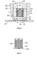
- Fig. 5 shows an inventive fastening unit 20 intended for attachment to a component by welding.
- the fastening unit 20 has a fastening part 21, which has a through-hole 23 that is equipped with an internal thread 22.
- the through-hole 23 passes through the fastening part 21 between a first end face 24 and a second end face 25.
- the fastening part 21 has a projecting, annular welding section 26, which surrounds the mouth of the through-hole 23 with a radial separation.
- An insert 1 is arranged in the through-hole 23 in such a manner that the wall 2 covers the internal thread 22 and contacts the thread ridges of the internal thread 22 with a force caused by elastic deformation such that the insert 1 is held by friction in the through-hole 23.
- the insert 1 is additionally arranged such that the sealing lip 5 is located on the second end face 25 and rests against the edge of the mouth of the through-hole 23 to form a seal. In this way, the insert 1 protects the internal thread 22 from the incursion of weld spatter and paint when the fastening unit 20 is welded to a component and subsequently is painted together therewith.
- Fig. 6 shows the fastening unit 20 held in a welding apparatus 30 in an arrangement intended for welding onto a component 31.
- the component 31 is provided with a hole 32 that passes through it, and the fastening unit 20 is aligned such that its through-hole 23 is essentially coaxial to the hole 32.
- the welding apparatus 30 grips the fastening part 21 with a welding gun 33.
- a tubular element 34 Located in the center of the welding gun 33 is a tubular element 34, which rests against the end face 24 of the fastening part 21 and has a passage 35 that opens into the through-passage 23.
- the insert 1 remains in the through-hole 23 in order to protect the internal thread 22 during subsequent painting steps.
- the insert 1 is removed from the through-hole 23 when the component 31 is attached to another component by means of a screw, which is to be screwed into the fastening part 21.
- the insert can be removed either by pushing it out with a punch-like tool, or using the screw to be screwed in, in that the screw drives the insert 1 ahead of it.
- Fig. 7 shows a modified embodiment of an insert 101, in which the sealing lip 105 is attached to the wall 102 by a predetermined breaking point 115.
- the sealing lip 105 tears off at the predetermined breaking point 115, and thus cannot prevent the insert 101 from being pushed out of the fastening part 21.
Landscapes
- Engineering & Computer Science (AREA)
- General Engineering & Computer Science (AREA)
- Mechanical Engineering (AREA)
- Physics & Mathematics (AREA)
- Plasma & Fusion (AREA)
- Connection Of Plates (AREA)
- Lining Or Joining Of Plastics Or The Like (AREA)
Abstract
Description
- The invention relates to a fastening unit for attachment to a component by welding, with a fastening part having a through-hole that is equipped with an internal thread and passes through the fastening part between a first and a second end face, and having a welding section that is located on the second end face and at least partially surrounds the through-hole, and with an insert located in the through-hole that at least partially seals the through-hole. The invention additionally relates to a method for attaching a fastening unit to a component by welding.
- Fastening units of the specified type are used in automotive manufacture, for example, to produce fastening points to which components and electrical connections can be reliably fastened using screws.
- In a fastening unit of the specified type known from
DE 199 54 354 A1 , the fastening part is a contact piece designed in the manner of a welding nut whose through-hole is sealed with a cap made of plastic in the vicinity of a fastening region designed as a welding section. The cap has a flexible collar that circumferentially contacts the lateral surface of the through-hole. The cap is intended to prevent welding spatter from entering the through-hole and to prevent particles of paint from penetrating the interior of the through-hole during subsequent painting. To protect the internal thread on the side opposite the welding section, a threaded stud is screwed into the internal thread of the contact piece. - Furthermore, from
DE 37 28 219 A1 , there is known a welding nut that can be welded to a part and that has a threaded hole sealed from the environment by inserts of elastic plastic inserted in the two openings of the threaded hole. When a threaded stud is screwed in, these inserts can be displaced by it into a location that exposes the courses of the nut's thread. - Fastening units of the specified type are frequently welded onto a component that has a hole in order to be able to fasten a screw that has been inserted through the hole. In this design, the fastening unit is welded onto the component such that its through-hole is essentially coaxial to the hole in the component. Now, it has become evident that when the fastening unit is being welded to the component, for example by means of drawn-arc welding, there exists the danger that material from the melt that is spattered during the welding process may adhere to the edge of the hole in the component in the form of small beads or droplets, thereby hindering the insertion of a screw through the hole into the internally threaded through-hole of the fastening part.
- For welding attachment by the electric drawn-arc method of a fastening element provided with a through-hole, it is known from
DE 196 25 886 B4 to introduce a gas at a pressure greater than that of the environment into the fastening element during the welding process in order to push melt arising at the welding location outward with the aid of the gas and prevent the melt from entering the through-hole of the fastening element as a result of the magnetic field of the arc. - The object of the invention is to design a fastening unit of the initially mentioned type and a method for attaching the fastening unit to a component by welding such that, after the welding process has been carried out, it is possible to screw a screw into the fastening part of the fastening unit unhindered and without additional rework.
- According to the invention, this object is attained by a fastening unit with the features specified in claim 1 and by a method for attaching the fastening unit by welding with the features specified in claim 15. Advantageous refinements and embodiments of the fastening unit are specified in the dependent claims.
- The fastening unit according to the invention has a fastening part with a through-hole that is equipped with an internal thread and passes through the fastening part between a first and a second end face, and with a welding section that is located on the second end face and at least partially surrounds the through-hole, and has an insert located in the through-hole that at least partially seals the through-hole, and is distinguished in that the insert covers the internal thread of the through-hole with a wall and has at least one through-passage that passes through the insert inside the wall and is open at its ends adjacent to the end faces of the fastening part.
- As a result of the design of the fastening unit according to the invention, the internal thread of the through-hole is efficaciously protected, so that neither particles spattered during the welding process nor paint from the subsequent painting of the component can reach the internal threads and prevent a screw from being screwed in.
- The insert of the fastening unit according to the invention further makes it possible, during the welding process, to blow a gas into the interior of the welding section and into the hole in the component to be fastened with the fastening unit and thereby prevent droplets or beads of the melt or other particles emerging during the welding process from depositing on the inner edge of the welding section and of the hole in the component. In this way, access is kept free during the welding process for a screw to be screwed into the fastening part, so that a fastening process to be performed at a later time is possible unimpeded and without prior rework.
- According to an advantageous embodiment of the invention, a mouth of the through-passage of the insert facing the welding section can have the form of a nozzle. It is especially advantageous when the nozzle is designed such that it generates a diverging stream. The blasting effect of the gas stream, and, hence, the blowing free of the edge of the hole adjoining the welding zone, can be considerably enhanced as a result of the nozzle shape of the mouth. Preferably, the nozzle is located inside the sealing lip.
- In another advantageous embodiment of the invention, the wall of the insert can have on at least one end, preferably the end facing the welding section, an annular sealing lip that rests against an adjacent edge of the mouth of the through-hole to form a seal. Such a sealing lip improves the protection of the internal thread at the start of the thread, which is especially important for ease of screwing in, in particular improving protection from the entry of paint during later painting. If necessary, both ends of the wall may also be provided with a sealing lip.
- The sealing lip can be elastically deformable to such a degree that it can be pushed through the through-hole together with the insert when the latter is removed.
- Alternatively, a predetermined breaking point can be provided between the sealing lip and the wall, allowing the sealing lip to tear off when the insert is pushed out of the through-hole.
- In order to facilitate the introduction of the insert into the through-hole of the fastening part, it is possible according to another proposal of the invention for the wall to have a pilot section on one end that tapers toward the end of the insert. Such a pilot section is especially advantageous when the elastically resilient wall has an outside diameter that is slightly larger than the inside diameter of the internal thread of the through-hole, in order to thus achieve a sufficiently stable and removable securing of the insert in the through-hole.
- According to another advantageous embodiment of the invention, provision can be made for the wall to have an external thread on its outside that engages the internal thread of the through-hole, wherein the insert has, on at least one end, a tool engagement region for the engagement of a rotating tool. In this design, the insert can be removed with the aid of a screwdriver or even with the aid of a screw to be screwed into the through-hole if the screw is provided with a suitable tool engagement region at its pilot end.
- According to another proposal of the invention, the insert can be provided with detent projections that latch into the internal thread of the through-hole to provide removable securing in the through-hole.
- According to another proposal of the invention, the insert can have an approximately cylindrical central body that the wall surrounds at a distance, wherein the central body is connected to the wall by webs extending in the longitudinal direction of the wall and wherein free spaces which form multiple through-passages are present between the webs. In this design, the insert can be provided at its end facing the welding section with an annular chamber in which the through-passages terminate and that has the shape of an annular nozzle.
- This refinement has the advantage that the through-passages have a cross-section that is considerably reduced in comparison to the through-hole, promoting the production of a gas stream with high flow velocity and corresponding blasting effect. The annular nozzle can be designed to produce a diverging stream.
- According to the invention, the insert is preferably made of a thermoplastic material. The insert can either be manufactured separately or through the involvement of the fastening part. In the latter case, the primary molding of the insert can take place in the internally threaded through-hole of the fastening part. This has the advantage that the insert fills the grooves of the internal thread in a paint-tight manner, and eliminates the step of inserting the insert in the through-hole.
- According to the invention, the method for attaching an inventive fastening unit to a component by welding is distinguished in that the fastening unit with the welding section is placed on the component having a hole such that it is essentially coaxial to the hole, in that the welding section is welded onto the component using an electric drawn-arc welding method, and in that a gas at a pressure greater than that of the environment is delivered to the through-passage of the insert during the welding process in such a way that a gas stream emerging from the through-passage strikes the welding zone and the edge of the hole.
- The invention is explained in detail below on the basis of example embodiments, which are shown in the drawings. They show:
- Fig. 1
- an end view of an insert for a fastening unit according to the invention,
- Fig. 2
- a perspective view of the insert from
Fig. 1 , - Fig. 3
- a cross-section III - III of the insert from
Fig. 1 , - Fig. 4
- a cross-section IV - IV of the insert from
Fig. 1 , - Fig. 5
- a fastening unit according to the invention,
- Fig. 6
- a fastening unit in the welding position on a component, and
- Fig. 7
- a cross-section of another embodiment of an insert for a fastening unit according to the invention.
- The insert 1 shown in
Figures 1 through 4 has the shape of a sleeve with acylindrical wall 2, which surrounds acavity 3. One end of thewall 2 forms apilot section 4 that is conically tapered on the outside toward the end of the insert 1. The other end of thewall 2 is provided with a sealinglip 5 whose outside diameter increases toward the face end of the insert 1. Thesealing lip 5 has asealing surface 6 in the manner of a concave molding, and its cross-section decreases toward the outer edge to ensure a resiliently elastic contact with the mating surface to be sealed. - Arranged in the
cavity 3 of the insert 1 is an essentially cylindricalcentral body 7 whose outside diameter is smaller than the inside diameter of thewall 2, by which means an annular chamber is formed between thecentral body 7 and thewall 2. The annular chamber is subdivided by firstradial webs 8 and second radial webs 9, which connect thecentral body 7 to thewall 2. Thewebs 8, 9 extend in the longitudinal direction of the insert and are arranged at a regular distance from one another, with each of the webs 9 being arranged between twowebs 8. Thewebs 8 have a greater axial length and a greater wall thickness than the webs 9. The sections of the annular chamber located between thewebs 8, 9 form through-passages 10 which extend within thewall 2 and are open at their face ends. Each of thewebs 8, 9 ends at a distance from the face ends of the insert 1, so each of the through-passages 10 terminates in an open section of the annular chamber formed between thewall 2 and thecentral body 7. At the end of the insert 1 provided with the sealinglip 5, the open section of the annular chamber forms anannular nozzle 11 whose mean diameter increases toward thenozzle orifice 12 at the end face of the insert 1. In this way, theannular nozzle 11 produces a diverging stream when a gas stream with overpressure is delivered to thecavity 3 on the end face of the insert 1 facing away from theannular nozzle 11. - At both its end faces, the
central body 7 hasrecesses 13, which are used for placement of an assembly or disassembly tool. -
Fig. 5 shows aninventive fastening unit 20 intended for attachment to a component by welding. Thefastening unit 20 has afastening part 21, which has a through-hole 23 that is equipped with aninternal thread 22. The through-hole 23 passes through thefastening part 21 between afirst end face 24 and asecond end face 25. On theend face 25, thefastening part 21 has a projecting,annular welding section 26, which surrounds the mouth of the through-hole 23 with a radial separation. - An insert 1 is arranged in the through-
hole 23 in such a manner that thewall 2 covers theinternal thread 22 and contacts the thread ridges of theinternal thread 22 with a force caused by elastic deformation such that the insert 1 is held by friction in the through-hole 23. The insert 1 is additionally arranged such that the sealinglip 5 is located on thesecond end face 25 and rests against the edge of the mouth of the through-hole 23 to form a seal. In this way, the insert 1 protects theinternal thread 22 from the incursion of weld spatter and paint when thefastening unit 20 is welded to a component and subsequently is painted together therewith. -
Fig. 6 shows thefastening unit 20 held in awelding apparatus 30 in an arrangement intended for welding onto acomponent 31. Thecomponent 31 is provided with ahole 32 that passes through it, and thefastening unit 20 is aligned such that its through-hole 23 is essentially coaxial to thehole 32. Thewelding apparatus 30 grips thefastening part 21 with a welding gun 33. Located in the center of the welding gun 33 is atubular element 34, which rests against theend face 24 of thefastening part 21 and has apassage 35 that opens into the through-passage 23. - To carry out a welding process, air or another gas at elevated pressure is conducted through the
passage 35 to thefastening unit 20. The air flows through the through-passages 10 of the insert 1 located in the through-hole 23 and passes out of thenozzle orifice 12 of theannular nozzle 11 in the form of a diverging stream into the space delimited by thewelding section 26, which it then exits through thehole 32. By means of the gas stream thus produced, welding spatter and melt particles are blown away during the welding process using the known drawn-arc method, and residue and droplets of the melt are kept from accumulating on the inside edge of thehole 32, which could thus prevent insertion of a screw into thehole 32. At the same time, the insert 1 reliably protects theinternal thread 22 from contaminants resulting from the welding process. - Even after the
fastening unit 20 has been welded, the insert 1 remains in the through-hole 23 in order to protect theinternal thread 22 during subsequent painting steps. - The insert 1 is removed from the through-
hole 23 when thecomponent 31 is attached to another component by means of a screw, which is to be screwed into thefastening part 21. The insert can be removed either by pushing it out with a punch-like tool, or using the screw to be screwed in, in that the screw drives the insert 1 ahead of it. -
Fig. 7 shows a modified embodiment of aninsert 101, in which the sealinglip 105 is attached to the wall 102 by apredetermined breaking point 115. When theinsert 101 is pushed into the through-hole 23 of thefastening part 21 for removal, the sealinglip 105 tears off at thepredetermined breaking point 115, and thus cannot prevent theinsert 101 from being pushed out of thefastening part 21.
Claims (15)
- Fastening unit for attachment to a component by welding, with a fastening part having a through-hole that is equipped with an internal thread and passes through the fastening part between a first and a second end face, and having a welding section that is located on the second end face and at least partially surrounds the through-hole, and with an insert located in the through-hole that at least partially seals the through-hole, characterized in that the insert (1) covers the internal thread of the through-hole (23) with a wall (2) and has at least one open-ended through-passage (10) that passes through the insert inside the wall (2) and is open at its ends adjacent to the end faces (24, 25) of the fastening part (21).
- Fastening unit according to claim 1, characterized in that a mouth of the through-passage (10) has the form of a nozzle (11).
- Fastening unit according to claim 2, characterized in that the nozzle (11) generates a diverging stream.
- Fastening unit according to one of the preceding claims, characterized in that the wall (2) of the insert (1) has, on at least one end, an annular sealing lip (5) that rests against an adjacent edge of the mouth of the through-hole (23) to form a seal.
- Fastening unit according to claim 4, characterized in that the sealing lip (5) is located on the end of the through-hole (23) adjacent to the welding section (26).
- Fastening unit according to one of claims 2 through 5, characterized in that the nozzle (11) is located inside the sealing lip (5).
- Fastening unit according to one of the preceding claims, characterized in that the wall (2) has a pilot section (4) on one end that tapers toward the end of the insert (1).
- Fastening unit according to one of the preceding claims, characterized in that the wall (2) is elastically resilient and has an outside diameter that is slightly larger than the inside diameter of the internal thread (22) of the through-hole (23).
- Fastening unit according to one of the preceding claims, characterized in that the wall (2) has an external thread on its outside that engages the internal thread (22) of the through-hole (23), wherein the insert (1) has, on at least one end, a tool engagement region for the engagement of a rotating tool.
- Fastening unit according to one of the preceding claims, characterized in that the insert (1) has detent projections that latch into the internal thread (22) of the through-hole (23) to provide removable securing in the through-hole (23).
- Fastening unit according to one of the preceding claims, characterized in that the insert (1) has a central body (7) that the wall (2) surrounds at a distance, in that the central body (7) is connected to the wall (2) by webs (8, 9) extending in the longitudinal direction of the wall (2), and in that free spaces which form through-passages (10) are present between the webs (8, 9).
- Fastening unit according to claim 11, characterized in that the through-passages (10) terminate in a common annular chamber that takes the form of an annular nozzle (11).
- Fastening unit according to one of the preceding claims, characterized in that the insert (1) is made of a thermoplastic material.
- Fastening unit according to claim 13, characterized in that the insert is molded in the through-hole (23) of the fastening part (21) provided with an internal thread (22).
- Method for attaching a fastening unit according to any one of the preceding claims to a component by welding characterized in that the fastening unit (20) with the welding section (26) is placed on the component (31) having a hole (32) such that it is essentially coaxial to the hole (32), in that the welding section (26) is welded onto the component (31) using an electric drawn-arc welding method, and in that a gas at a pressure greater than that of the environment is delivered to the through-passage (19) of the insert (1) during the welding process in such a way that a gas stream emerging from the through-passage (10) strikes the welding zone and the edge of the hole (32).
Applications Claiming Priority (1)
| Application Number | Priority Date | Filing Date | Title |
|---|---|---|---|
| DE202010012368U DE202010012368U1 (en) | 2010-09-08 | 2010-09-08 | Fastening unit for the welding connection of a fastening unit with a component |
Publications (3)
| Publication Number | Publication Date |
|---|---|
| EP2428302A2 true EP2428302A2 (en) | 2012-03-14 |
| EP2428302A3 EP2428302A3 (en) | 2014-06-04 |
| EP2428302B1 EP2428302B1 (en) | 2016-10-26 |
Family
ID=43218333
Family Applications (1)
| Application Number | Title | Priority Date | Filing Date |
|---|---|---|---|
| EP11180309.4A Not-in-force EP2428302B1 (en) | 2010-09-08 | 2011-09-07 | Fastening unit and method for attaching a fastening unit to a component by welding |
Country Status (2)
| Country | Link |
|---|---|
| EP (1) | EP2428302B1 (en) |
| DE (1) | DE202010012368U1 (en) |
Families Citing this family (2)
| Publication number | Priority date | Publication date | Assignee | Title |
|---|---|---|---|---|
| DE102012019849B4 (en) * | 2012-10-10 | 2023-11-02 | Böllhoff Verbindungstechnik GmbH | Component with sealing plug and method for forming a component insert |
| DE102016214771A1 (en) * | 2016-08-09 | 2018-02-15 | Mahle International Gmbh | Connection method of an attachment with a hollow shaft |
Citations (3)
| Publication number | Priority date | Publication date | Assignee | Title |
|---|---|---|---|---|
| DE3728219A1 (en) | 1987-08-24 | 1989-03-09 | Fastenrath Befestigungstechnik | Nut, for example weld nut or insert nut |
| DE19954354A1 (en) | 1999-11-11 | 2001-05-17 | Emhart Inc | Connection device with cap |
| DE19625886B4 (en) | 1996-06-27 | 2007-03-22 | Newfrey Llc, Newark | Electric welding apparatus and method for welding a fastener |
Family Cites Families (3)
| Publication number | Priority date | Publication date | Assignee | Title |
|---|---|---|---|---|
| DE4200199A1 (en) * | 1992-01-07 | 1993-07-08 | Emhart Inc | METHOD FOR ELECTRICALLY WELDING TWO WELDED PARTS |
| JPH06320288A (en) * | 1993-05-13 | 1994-11-22 | Futaba Sangyo Kk | Welding method for weld nut |
| GB0021316D0 (en) * | 2000-08-30 | 2000-10-18 | Emhart Inc | Improved arc welding method and apparatus |
-
2010
- 2010-09-08 DE DE202010012368U patent/DE202010012368U1/en not_active Expired - Lifetime
-
2011
- 2011-09-07 EP EP11180309.4A patent/EP2428302B1/en not_active Not-in-force
Patent Citations (3)
| Publication number | Priority date | Publication date | Assignee | Title |
|---|---|---|---|---|
| DE3728219A1 (en) | 1987-08-24 | 1989-03-09 | Fastenrath Befestigungstechnik | Nut, for example weld nut or insert nut |
| DE19625886B4 (en) | 1996-06-27 | 2007-03-22 | Newfrey Llc, Newark | Electric welding apparatus and method for welding a fastener |
| DE19954354A1 (en) | 1999-11-11 | 2001-05-17 | Emhart Inc | Connection device with cap |
Also Published As
| Publication number | Publication date |
|---|---|
| DE202010012368U1 (en) | 2010-11-25 |
| EP2428302A3 (en) | 2014-06-04 |
| EP2428302B1 (en) | 2016-10-26 |
Similar Documents
| Publication | Publication Date | Title |
|---|---|---|
| EP2692449B1 (en) | Spray gun | |
| EP3036163B1 (en) | Cap with injected sealant | |
| CN101410188B (en) | spray gun | |
| EP3027917B1 (en) | Cap to accommodate washers | |
| US8711541B2 (en) | Lightning-protective explosion-preventive fastener | |
| US11141747B2 (en) | Nozzle arrangement for a spray gun | |
| EP3106380B1 (en) | Cap, cap mold, securing structure part using cap, and method for mounting cap | |
| KR20110113174A (en) | Compressed air tank and manufacturing method for ATV | |
| EP3546375B1 (en) | Cap with sealant flow path | |
| US9333527B2 (en) | Nozzle for applying sealants | |
| US12097519B2 (en) | Sealing element for sealing a transition between a spray gun body and an attachment of a spray gun, attachment, in particular a paint nozzle arrangement for a spray gun and a spray gun, in particular a paint spray gun | |
| WO2015197375A1 (en) | Pressure vessel | |
| EP2428302B1 (en) | Fastening unit and method for attaching a fastening unit to a component by welding | |
| US9616440B2 (en) | Electrode holder and jet nozzle for a powder spray gun operable at high voltage | |
| US5233154A (en) | Plasma torch | |
| JP2011125906A (en) | Nozzle for laser beam machining | |
| EP3247502B1 (en) | Bell cup of a rotary atomizer or deflecting air ring with an isolating coating | |
| EP3992479B1 (en) | Spark containment cap | |
| JP4664152B2 (en) | Ionizer nozzle | |
| JP4990081B2 (en) | Fuel supply system | |
| CN105818332A (en) | Nozzle for injection molding machine | |
| AU3811700A (en) | Two-chamber tube | |
| CN111216911A (en) | Spark suppressing cap | |
| JP6174278B1 (en) | Lance | |
| JP3136215U (en) | nozzle |
Legal Events
| Date | Code | Title | Description |
|---|---|---|---|
| AK | Designated contracting states |
Kind code of ref document: A2 Designated state(s): AL AT BE BG CH CY CZ DE DK EE ES FI FR GB GR HR HU IE IS IT LI LT LU LV MC MK MT NL NO PL PT RO RS SE SI SK SM TR |
|
| AX | Request for extension of the european patent |
Extension state: BA ME |
|
| PUAI | Public reference made under article 153(3) epc to a published international application that has entered the european phase |
Free format text: ORIGINAL CODE: 0009012 |
|
| PUAL | Search report despatched |
Free format text: ORIGINAL CODE: 0009013 |
|
| AK | Designated contracting states |
Kind code of ref document: A3 Designated state(s): AL AT BE BG CH CY CZ DE DK EE ES FI FR GB GR HR HU IE IS IT LI LT LU LV MC MK MT NL NO PL PT RO RS SE SI SK SM TR |
|
| AX | Request for extension of the european patent |
Extension state: BA ME |
|
| RIC1 | Information provided on ipc code assigned before grant |
Ipc: F16B 37/06 20060101ALN20140430BHEP Ipc: B23K 9/20 20060101AFI20140430BHEP |
|
| 17P | Request for examination filed |
Effective date: 20141104 |
|
| RBV | Designated contracting states (corrected) |
Designated state(s): AL AT BE BG CH CY CZ DE DK EE ES FI FR GB GR HR HU IE IS IT LI LT LU LV MC MK MT NL NO PL PT RO RS SE SI SK SM TR |
|
| RAP1 | Party data changed (applicant data changed or rights of an application transferred) |
Owner name: NEWFREY LLC |
|
| RIC1 | Information provided on ipc code assigned before grant |
Ipc: F16B 37/06 20060101ALN20160418BHEP Ipc: B23K 9/20 20060101AFI20160418BHEP |
|
| GRAP | Despatch of communication of intention to grant a patent |
Free format text: ORIGINAL CODE: EPIDOSNIGR1 |
|
| INTG | Intention to grant announced |
Effective date: 20160602 |
|
| GRAS | Grant fee paid |
Free format text: ORIGINAL CODE: EPIDOSNIGR3 |
|
| GRAA | (expected) grant |
Free format text: ORIGINAL CODE: 0009210 |
|
| AK | Designated contracting states |
Kind code of ref document: B1 Designated state(s): AL AT BE BG CH CY CZ DE DK EE ES FI FR GB GR HR HU IE IS IT LI LT LU LV MC MK MT NL NO PL PT RO RS SE SI SK SM TR |
|
| REG | Reference to a national code |
Ref country code: GB Ref legal event code: FG4D |
|
| REG | Reference to a national code |
Ref country code: CH Ref legal event code: EP |
|
| REG | Reference to a national code |
Ref country code: AT Ref legal event code: REF Ref document number: 839653 Country of ref document: AT Kind code of ref document: T Effective date: 20161115 |
|
| REG | Reference to a national code |
Ref country code: IE Ref legal event code: FG4D |
|
| REG | Reference to a national code |
Ref country code: DE Ref legal event code: R096 Ref document number: 602011031614 Country of ref document: DE |
|
| REG | Reference to a national code |
Ref country code: LT Ref legal event code: MG4D |
|
| PG25 | Lapsed in a contracting state [announced via postgrant information from national office to epo] |
Ref country code: LV Free format text: LAPSE BECAUSE OF FAILURE TO SUBMIT A TRANSLATION OF THE DESCRIPTION OR TO PAY THE FEE WITHIN THE PRESCRIBED TIME-LIMIT Effective date: 20161026 |
|
| REG | Reference to a national code |
Ref country code: NL Ref legal event code: MP Effective date: 20161026 |
|
| REG | Reference to a national code |
Ref country code: AT Ref legal event code: MK05 Ref document number: 839653 Country of ref document: AT Kind code of ref document: T Effective date: 20161026 |
|
| PG25 | Lapsed in a contracting state [announced via postgrant information from national office to epo] |
Ref country code: SE Free format text: LAPSE BECAUSE OF FAILURE TO SUBMIT A TRANSLATION OF THE DESCRIPTION OR TO PAY THE FEE WITHIN THE PRESCRIBED TIME-LIMIT Effective date: 20161026 Ref country code: NO Free format text: LAPSE BECAUSE OF FAILURE TO SUBMIT A TRANSLATION OF THE DESCRIPTION OR TO PAY THE FEE WITHIN THE PRESCRIBED TIME-LIMIT Effective date: 20170126 Ref country code: LT Free format text: LAPSE BECAUSE OF FAILURE TO SUBMIT A TRANSLATION OF THE DESCRIPTION OR TO PAY THE FEE WITHIN THE PRESCRIBED TIME-LIMIT Effective date: 20161026 Ref country code: GR Free format text: LAPSE BECAUSE OF FAILURE TO SUBMIT A TRANSLATION OF THE DESCRIPTION OR TO PAY THE FEE WITHIN THE PRESCRIBED TIME-LIMIT Effective date: 20170127 |
|
| PG25 | Lapsed in a contracting state [announced via postgrant information from national office to epo] |
Ref country code: PL Free format text: LAPSE BECAUSE OF FAILURE TO SUBMIT A TRANSLATION OF THE DESCRIPTION OR TO PAY THE FEE WITHIN THE PRESCRIBED TIME-LIMIT Effective date: 20161026 Ref country code: PT Free format text: LAPSE BECAUSE OF FAILURE TO SUBMIT A TRANSLATION OF THE DESCRIPTION OR TO PAY THE FEE WITHIN THE PRESCRIBED TIME-LIMIT Effective date: 20170227 Ref country code: BE Free format text: LAPSE BECAUSE OF FAILURE TO SUBMIT A TRANSLATION OF THE DESCRIPTION OR TO PAY THE FEE WITHIN THE PRESCRIBED TIME-LIMIT Effective date: 20161026 Ref country code: FI Free format text: LAPSE BECAUSE OF FAILURE TO SUBMIT A TRANSLATION OF THE DESCRIPTION OR TO PAY THE FEE WITHIN THE PRESCRIBED TIME-LIMIT Effective date: 20161026 Ref country code: HR Free format text: LAPSE BECAUSE OF FAILURE TO SUBMIT A TRANSLATION OF THE DESCRIPTION OR TO PAY THE FEE WITHIN THE PRESCRIBED TIME-LIMIT Effective date: 20161026 Ref country code: NL Free format text: LAPSE BECAUSE OF FAILURE TO SUBMIT A TRANSLATION OF THE DESCRIPTION OR TO PAY THE FEE WITHIN THE PRESCRIBED TIME-LIMIT Effective date: 20161026 Ref country code: RS Free format text: LAPSE BECAUSE OF FAILURE TO SUBMIT A TRANSLATION OF THE DESCRIPTION OR TO PAY THE FEE WITHIN THE PRESCRIBED TIME-LIMIT Effective date: 20161026 Ref country code: AT Free format text: LAPSE BECAUSE OF FAILURE TO SUBMIT A TRANSLATION OF THE DESCRIPTION OR TO PAY THE FEE WITHIN THE PRESCRIBED TIME-LIMIT Effective date: 20161026 Ref country code: ES Free format text: LAPSE BECAUSE OF FAILURE TO SUBMIT A TRANSLATION OF THE DESCRIPTION OR TO PAY THE FEE WITHIN THE PRESCRIBED TIME-LIMIT Effective date: 20161026 Ref country code: IS Free format text: LAPSE BECAUSE OF FAILURE TO SUBMIT A TRANSLATION OF THE DESCRIPTION OR TO PAY THE FEE WITHIN THE PRESCRIBED TIME-LIMIT Effective date: 20170226 |
|
| REG | Reference to a national code |
Ref country code: DE Ref legal event code: R097 Ref document number: 602011031614 Country of ref document: DE |
|
| PG25 | Lapsed in a contracting state [announced via postgrant information from national office to epo] |
Ref country code: DK Free format text: LAPSE BECAUSE OF FAILURE TO SUBMIT A TRANSLATION OF THE DESCRIPTION OR TO PAY THE FEE WITHIN THE PRESCRIBED TIME-LIMIT Effective date: 20161026 Ref country code: EE Free format text: LAPSE BECAUSE OF FAILURE TO SUBMIT A TRANSLATION OF THE DESCRIPTION OR TO PAY THE FEE WITHIN THE PRESCRIBED TIME-LIMIT Effective date: 20161026 Ref country code: CZ Free format text: LAPSE BECAUSE OF FAILURE TO SUBMIT A TRANSLATION OF THE DESCRIPTION OR TO PAY THE FEE WITHIN THE PRESCRIBED TIME-LIMIT Effective date: 20161026 Ref country code: RO Free format text: LAPSE BECAUSE OF FAILURE TO SUBMIT A TRANSLATION OF THE DESCRIPTION OR TO PAY THE FEE WITHIN THE PRESCRIBED TIME-LIMIT Effective date: 20161026 Ref country code: SK Free format text: LAPSE BECAUSE OF FAILURE TO SUBMIT A TRANSLATION OF THE DESCRIPTION OR TO PAY THE FEE WITHIN THE PRESCRIBED TIME-LIMIT Effective date: 20161026 |
|
| REG | Reference to a national code |
Ref country code: FR Ref legal event code: PLFP Year of fee payment: 7 |
|
| PG25 | Lapsed in a contracting state [announced via postgrant information from national office to epo] |
Ref country code: IT Free format text: LAPSE BECAUSE OF FAILURE TO SUBMIT A TRANSLATION OF THE DESCRIPTION OR TO PAY THE FEE WITHIN THE PRESCRIBED TIME-LIMIT Effective date: 20161026 Ref country code: BG Free format text: LAPSE BECAUSE OF FAILURE TO SUBMIT A TRANSLATION OF THE DESCRIPTION OR TO PAY THE FEE WITHIN THE PRESCRIBED TIME-LIMIT Effective date: 20170126 Ref country code: SM Free format text: LAPSE BECAUSE OF FAILURE TO SUBMIT A TRANSLATION OF THE DESCRIPTION OR TO PAY THE FEE WITHIN THE PRESCRIBED TIME-LIMIT Effective date: 20161026 |
|
| PLBE | No opposition filed within time limit |
Free format text: ORIGINAL CODE: 0009261 |
|
| STAA | Information on the status of an ep patent application or granted ep patent |
Free format text: STATUS: NO OPPOSITION FILED WITHIN TIME LIMIT |
|
| 26N | No opposition filed |
Effective date: 20170727 |
|
| PG25 | Lapsed in a contracting state [announced via postgrant information from national office to epo] |
Ref country code: SI Free format text: LAPSE BECAUSE OF FAILURE TO SUBMIT A TRANSLATION OF THE DESCRIPTION OR TO PAY THE FEE WITHIN THE PRESCRIBED TIME-LIMIT Effective date: 20161026 |
|
| REG | Reference to a national code |
Ref country code: CH Ref legal event code: PL |
|
| PG25 | Lapsed in a contracting state [announced via postgrant information from national office to epo] |
Ref country code: MC Free format text: LAPSE BECAUSE OF FAILURE TO SUBMIT A TRANSLATION OF THE DESCRIPTION OR TO PAY THE FEE WITHIN THE PRESCRIBED TIME-LIMIT Effective date: 20161026 |
|
| REG | Reference to a national code |
Ref country code: IE Ref legal event code: MM4A |
|
| PG25 | Lapsed in a contracting state [announced via postgrant information from national office to epo] |
Ref country code: LU Free format text: LAPSE BECAUSE OF NON-PAYMENT OF DUE FEES Effective date: 20170907 |
|
| PG25 | Lapsed in a contracting state [announced via postgrant information from national office to epo] |
Ref country code: CH Free format text: LAPSE BECAUSE OF NON-PAYMENT OF DUE FEES Effective date: 20170930 Ref country code: IE Free format text: LAPSE BECAUSE OF NON-PAYMENT OF DUE FEES Effective date: 20170907 Ref country code: LI Free format text: LAPSE BECAUSE OF NON-PAYMENT OF DUE FEES Effective date: 20170930 |
|
| REG | Reference to a national code |
Ref country code: FR Ref legal event code: PLFP Year of fee payment: 8 |
|
| PG25 | Lapsed in a contracting state [announced via postgrant information from national office to epo] |
Ref country code: MT Free format text: LAPSE BECAUSE OF NON-PAYMENT OF DUE FEES Effective date: 20170907 |
|
| PG25 | Lapsed in a contracting state [announced via postgrant information from national office to epo] |
Ref country code: HU Free format text: LAPSE BECAUSE OF FAILURE TO SUBMIT A TRANSLATION OF THE DESCRIPTION OR TO PAY THE FEE WITHIN THE PRESCRIBED TIME-LIMIT; INVALID AB INITIO Effective date: 20110907 |
|
| PG25 | Lapsed in a contracting state [announced via postgrant information from national office to epo] |
Ref country code: CY Free format text: LAPSE BECAUSE OF NON-PAYMENT OF DUE FEES Effective date: 20161026 |
|
| PG25 | Lapsed in a contracting state [announced via postgrant information from national office to epo] |
Ref country code: MK Free format text: LAPSE BECAUSE OF FAILURE TO SUBMIT A TRANSLATION OF THE DESCRIPTION OR TO PAY THE FEE WITHIN THE PRESCRIBED TIME-LIMIT Effective date: 20161026 |
|
| PG25 | Lapsed in a contracting state [announced via postgrant information from national office to epo] |
Ref country code: TR Free format text: LAPSE BECAUSE OF FAILURE TO SUBMIT A TRANSLATION OF THE DESCRIPTION OR TO PAY THE FEE WITHIN THE PRESCRIBED TIME-LIMIT Effective date: 20161026 |
|
| PG25 | Lapsed in a contracting state [announced via postgrant information from national office to epo] |
Ref country code: AL Free format text: LAPSE BECAUSE OF FAILURE TO SUBMIT A TRANSLATION OF THE DESCRIPTION OR TO PAY THE FEE WITHIN THE PRESCRIBED TIME-LIMIT Effective date: 20161026 |
|
| PGFP | Annual fee paid to national office [announced via postgrant information from national office to epo] |
Ref country code: GB Payment date: 20220714 Year of fee payment: 12 Ref country code: DE Payment date: 20220609 Year of fee payment: 12 |
|
| PGFP | Annual fee paid to national office [announced via postgrant information from national office to epo] |
Ref country code: FR Payment date: 20220709 Year of fee payment: 12 |
|
| P01 | Opt-out of the competence of the unified patent court (upc) registered |
Effective date: 20230912 |
|
| REG | Reference to a national code |
Ref country code: DE Ref legal event code: R119 Ref document number: 602011031614 Country of ref document: DE |
|
| GBPC | Gb: european patent ceased through non-payment of renewal fee |
Effective date: 20230907 |
|
| PG25 | Lapsed in a contracting state [announced via postgrant information from national office to epo] |
Ref country code: GB Free format text: LAPSE BECAUSE OF NON-PAYMENT OF DUE FEES Effective date: 20230907 |
|
| PG25 | Lapsed in a contracting state [announced via postgrant information from national office to epo] |
Ref country code: GB Free format text: LAPSE BECAUSE OF NON-PAYMENT OF DUE FEES Effective date: 20230907 Ref country code: FR Free format text: LAPSE BECAUSE OF NON-PAYMENT OF DUE FEES Effective date: 20230930 Ref country code: DE Free format text: LAPSE BECAUSE OF NON-PAYMENT OF DUE FEES Effective date: 20240403 |