EP2428294A2 - Fuel injector clamp - Google Patents
Fuel injector clamp Download PDFInfo
- Publication number
- EP2428294A2 EP2428294A2 EP11250747A EP11250747A EP2428294A2 EP 2428294 A2 EP2428294 A2 EP 2428294A2 EP 11250747 A EP11250747 A EP 11250747A EP 11250747 A EP11250747 A EP 11250747A EP 2428294 A2 EP2428294 A2 EP 2428294A2
- Authority
- EP
- European Patent Office
- Prior art keywords
- fuel injector
- injector clamp
- powder metal
- center portion
- clamp
- Prior art date
- Legal status (The legal status is an assumption and is not a legal conclusion. Google has not performed a legal analysis and makes no representation as to the accuracy of the status listed.)
- Granted
Links
- 239000000446 fuel Substances 0.000 title claims abstract description 65
- 239000002184 metal Substances 0.000 claims abstract description 35
- 229910052751 metal Inorganic materials 0.000 claims abstract description 35
- 239000000843 powder Substances 0.000 claims abstract description 35
- 238000000034 method Methods 0.000 claims abstract description 20
- XEEYBQQBJWHFJM-UHFFFAOYSA-N Iron Chemical compound [Fe] XEEYBQQBJWHFJM-UHFFFAOYSA-N 0.000 claims abstract description 10
- OKTJSMMVPCPJKN-UHFFFAOYSA-N Carbon Chemical compound [C] OKTJSMMVPCPJKN-UHFFFAOYSA-N 0.000 claims abstract description 5
- RYGMFSIKBFXOCR-UHFFFAOYSA-N Copper Chemical compound [Cu] RYGMFSIKBFXOCR-UHFFFAOYSA-N 0.000 claims abstract description 5
- 229910052799 carbon Inorganic materials 0.000 claims abstract description 5
- 229910052802 copper Inorganic materials 0.000 claims abstract description 5
- 239000010949 copper Substances 0.000 claims abstract description 5
- 229910052742 iron Inorganic materials 0.000 claims abstract description 5
- 239000000314 lubricant Substances 0.000 claims description 4
- 238000005245 sintering Methods 0.000 claims 4
- 239000011248 coating agent Substances 0.000 claims 1
- 238000000576 coating method Methods 0.000 claims 1
- 239000001993 wax Substances 0.000 claims 1
- 238000004519 manufacturing process Methods 0.000 description 2
- VGGSQFUCUMXWEO-UHFFFAOYSA-N Ethene Chemical compound C=C VGGSQFUCUMXWEO-UHFFFAOYSA-N 0.000 description 1
- 239000005977 Ethylene Substances 0.000 description 1
- 229910000831 Steel Inorganic materials 0.000 description 1
- 238000002485 combustion reaction Methods 0.000 description 1
- 238000005336 cracking Methods 0.000 description 1
- 238000005495 investment casting Methods 0.000 description 1
- 150000002739 metals Chemical class 0.000 description 1
- 238000004663 powder metallurgy Methods 0.000 description 1
- 238000007789 sealing Methods 0.000 description 1
- 229940037312 stearamide Drugs 0.000 description 1
- 239000010959 steel Substances 0.000 description 1
Images

Classifications
-
- F—MECHANICAL ENGINEERING; LIGHTING; HEATING; WEAPONS; BLASTING
- F02—COMBUSTION ENGINES; HOT-GAS OR COMBUSTION-PRODUCT ENGINE PLANTS
- F02M—SUPPLYING COMBUSTION ENGINES IN GENERAL WITH COMBUSTIBLE MIXTURES OR CONSTITUENTS THEREOF
- F02M61/00—Fuel-injectors not provided for in groups F02M39/00 - F02M57/00 or F02M67/00
- F02M61/14—Arrangements of injectors with respect to engines; Mounting of injectors
-
- B—PERFORMING OPERATIONS; TRANSPORTING
- B22—CASTING; POWDER METALLURGY
- B22F—WORKING METALLIC POWDER; MANUFACTURE OF ARTICLES FROM METALLIC POWDER; MAKING METALLIC POWDER; APPARATUS OR DEVICES SPECIALLY ADAPTED FOR METALLIC POWDER
- B22F3/00—Manufacture of workpieces or articles from metallic powder characterised by the manner of compacting or sintering; Apparatus specially adapted therefor ; Presses and furnaces
- B22F3/10—Sintering only
- B22F3/1017—Multiple heating or additional steps
-
- B—PERFORMING OPERATIONS; TRANSPORTING
- B22—CASTING; POWDER METALLURGY
- B22F—WORKING METALLIC POWDER; MANUFACTURE OF ARTICLES FROM METALLIC POWDER; MAKING METALLIC POWDER; APPARATUS OR DEVICES SPECIALLY ADAPTED FOR METALLIC POWDER
- B22F3/00—Manufacture of workpieces or articles from metallic powder characterised by the manner of compacting or sintering; Apparatus specially adapted therefor ; Presses and furnaces
- B22F3/12—Both compacting and sintering
- B22F3/16—Both compacting and sintering in successive or repeated steps
-
- B—PERFORMING OPERATIONS; TRANSPORTING
- B22—CASTING; POWDER METALLURGY
- B22F—WORKING METALLIC POWDER; MANUFACTURE OF ARTICLES FROM METALLIC POWDER; MAKING METALLIC POWDER; APPARATUS OR DEVICES SPECIALLY ADAPTED FOR METALLIC POWDER
- B22F5/00—Manufacture of workpieces or articles from metallic powder characterised by the special shape of the product
- B22F5/10—Manufacture of workpieces or articles from metallic powder characterised by the special shape of the product of articles with cavities or holes, not otherwise provided for in the preceding subgroups
-
- C—CHEMISTRY; METALLURGY
- C22—METALLURGY; FERROUS OR NON-FERROUS ALLOYS; TREATMENT OF ALLOYS OR NON-FERROUS METALS
- C22C—ALLOYS
- C22C33/00—Making ferrous alloys
- C22C33/02—Making ferrous alloys by powder metallurgy
- C22C33/0257—Making ferrous alloys by powder metallurgy characterised by the range of the alloying elements
- C22C33/0264—Making ferrous alloys by powder metallurgy characterised by the range of the alloying elements the maximum content of each alloying element not exceeding 5%
-
- C—CHEMISTRY; METALLURGY
- C22—METALLURGY; FERROUS OR NON-FERROUS ALLOYS; TREATMENT OF ALLOYS OR NON-FERROUS METALS
- C22C—ALLOYS
- C22C33/00—Making ferrous alloys
- C22C33/02—Making ferrous alloys by powder metallurgy
- C22C33/0257—Making ferrous alloys by powder metallurgy characterised by the range of the alloying elements
- C22C33/0278—Making ferrous alloys by powder metallurgy characterised by the range of the alloying elements with at least one alloying element having a minimum content above 5%
-
- F—MECHANICAL ENGINEERING; LIGHTING; HEATING; WEAPONS; BLASTING
- F02—COMBUSTION ENGINES; HOT-GAS OR COMBUSTION-PRODUCT ENGINE PLANTS
- F02M—SUPPLYING COMBUSTION ENGINES IN GENERAL WITH COMBUSTIBLE MIXTURES OR CONSTITUENTS THEREOF
- F02M61/00—Fuel-injectors not provided for in groups F02M39/00 - F02M57/00 or F02M67/00
- F02M61/16—Details not provided for in, or of interest apart from, the apparatus of groups F02M61/02 - F02M61/14
- F02M61/166—Selection of particular materials
-
- F—MECHANICAL ENGINEERING; LIGHTING; HEATING; WEAPONS; BLASTING
- F02—COMBUSTION ENGINES; HOT-GAS OR COMBUSTION-PRODUCT ENGINE PLANTS
- F02M—SUPPLYING COMBUSTION ENGINES IN GENERAL WITH COMBUSTIBLE MIXTURES OR CONSTITUENTS THEREOF
- F02M2200/00—Details of fuel-injection apparatus, not otherwise provided for
- F02M2200/85—Mounting of fuel injection apparatus
- F02M2200/855—Mounting of fuel injection apparatus using clamp elements or fastening means, e.g. bolts or screws
-
- F—MECHANICAL ENGINEERING; LIGHTING; HEATING; WEAPONS; BLASTING
- F02—COMBUSTION ENGINES; HOT-GAS OR COMBUSTION-PRODUCT ENGINE PLANTS
- F02M—SUPPLYING COMBUSTION ENGINES IN GENERAL WITH COMBUSTIBLE MIXTURES OR CONSTITUENTS THEREOF
- F02M2200/00—Details of fuel-injection apparatus, not otherwise provided for
- F02M2200/90—Selection of particular materials
- F02M2200/9092—Sintered materials
Definitions
- the present invention relates to a method of forming a fuel injector clamp and, more particularly, to a method of forming a fuel injector clamp using a powder metal process and to the fuel injector clamp itself.
- Fuel injectors in internal combustion gasoline, diesel and other engines are often held in place by a clamping device, termed a fuel injector clamp.
- a fuel injector clamp can be made from forged steel or investment castings; some fuel injector clamps are made from suitable powder metals as well.
- Such fuel injector clamps must be sufficiently strong and rigid to assure proper holding and sealing of the fuel injector during periods of stress.
- the fuel injector clamp In certain designs of fuel injector clamps, it is desirable for the fuel injector clamp to be deformable by stress or load. It is important that the fuel injector clamp be able to be deformed within elastic limits such that, the fuel injector clamp responds elastically without failure or cracking.
- a method of manufacturing a fuel injector clamp utilizing powder metal techniques includes a powder metal technique involving the provision of a powder metal charge comprising in percent by weight, 0.6-0.9 carbon, 1.5-3.9 copper, 93.2-97.9 iron, with the balance other elements.
- the powder metal charge is die compacted to a density of 7.0-7.1 grams per cubic centimeter, and then pre-sintered at 1500-1600 degrees Fahrenheit to form a powder metal blank.
- the powder metal blank is then coated with a suitable lubricant.
- the lubricated powder metal blank is then re-compacted to density of at least 7.3 grams per cubic centimeter and then sintered at about 2050 degrees Fahrenheit to form a final powder metal blank in the desired configuration of the fuel injector clamp.
- a fuel injector clamp is also provided that is comprised of a compacted sintered powder metal.
- the fuel injector clamp itself comprises a unitary structure having a generally cylindrical center portion itself having a center opening.
- a first wing portion extends laterally therefrom, and a second wing portion extends laterally therefrom at a 180 degree angle from the first wing portion.
- the center portion of the fuel injector clamp includes a lower surface, with a first support edge extending downwardly from the center portion lower surface adjacent the intersection with the first wing portion.
- a second support edge extends downwardly from the center portion lower surface adjacent the intersection with the second wing portion.
- the center portion lower surface extends downwardly beyond the lower limits of the first support edge and second support edge.
- the first and second support edges move downwardly elastically to a plane even with the center portion lower surface.
- a method of forming a fuel injector clamp utilizing powder metallurgy techniques comprises the steps of providing a powder metal charge comprising, in percent by weight, 0.6-0.9 carbon, 1.5-3.9 copper, 93.2-97.9 iron, with the balance other elements.
- the powder metal charge is die compacted to the blank shape of the fuel injector clamp to a density of 7.0-7.1 grams per cubic centimeter.
- the compacted blank is then pre-sintered at 1500-1600 degrees Fahrenheit, for a period of 15 5 minutes to form a powder metal blank.
- This powder metal blank is then coated with suitable lubricant such as EBS-WAX (Ethylene Bi-Stearamide).
- the lubricated powder metal blank is re-compacted to a density of at least 7.3 grams per cubic centimeter and then sintered at about 2050 degrees Fahrenheit for a period of 10 to 30 minutes to form final powder metal blank.
- the final powder metal blank has a ductility and elongation to allow strain without permanent deformation of at least two percent.
- Fuel injector clamp 10 is shown in accordance with the first embodiment of the present invention.
- Fuel injector clamp 10 is comprised of a powder metal made in accordance with the method described above.
- Fuel injector clamp 10 comprises a generally cylindrical center portion 14 having an opening axially there through. Center portion 14 includes a lower surface 16.
- First wing portion 18 extents laterally from center portion 14 and includes an axial opening 22 extending vertically there through.
- Fuel injector clamp 10 also includes a second wing portion 20 extending laterally from center portion 14 in a direction 180 degrees from first wing portion 18.
- Second wing portion 20 also includes an axial opening 24 that extends vertically there through.
- Center portion 14 also includes lower surface 16 that itself includes a first support edge 26 extending downwardly along a portion of lower surface 16 adjacent the intersection of first wing portion 18 and center portion 14.
- a second support edge 28 extends downwardly along a portion of lower surface 16 adjacent the intersection of second wing portion 20 with center portion 14.
- Fuel injector clamp 20 is seen to receive fuel injector 30.
- Fuel injector 30 is seen to comprise a generally cylindrical elongated structure having a generally cylindrical lower body section 32, a generally cylindrical upper body section 34, and a support 36 located between lower body section 32 and upper body section 34.
- Upper body section 34 is seen to pass through the opening in center portion 14 of fuel injector clamp 10.
- fuel injector clamp 10 under an unloaded condition, fuel injector clamp 10 is seen to have a lower portion 21 of its center portion 14 contacting upper surface 38 of fuel injector support 36. Under a no load condition, first support edge 26 and second support edge 28 do not contact upper surface 38 of fuel injector support 36. As shown in Fig. 3 , under a load condition, fuel injector clamp 10 would deform elastically such that first support edge 26 and second support edge 28 would move downwardly to engage upper surface 38 of fuel injector support 36.
- first support edge 26 and second support edge 28 each of between 0.63-1.0 milimeters (0.024-0.040 inches).
Landscapes
- Engineering & Computer Science (AREA)
- Mechanical Engineering (AREA)
- Chemical & Material Sciences (AREA)
- Manufacturing & Machinery (AREA)
- Combustion & Propulsion (AREA)
- General Engineering & Computer Science (AREA)
- Materials Engineering (AREA)
- Metallurgy (AREA)
- Organic Chemistry (AREA)
- Fuel-Injection Apparatus (AREA)
- Powder Metallurgy (AREA)
- Cylinder Crankcases Of Internal Combustion Engines (AREA)
Abstract
Description
- The present invention relates to a method of forming a fuel injector clamp and, more particularly, to a method of forming a fuel injector clamp using a powder metal process and to the fuel injector clamp itself.
- Fuel injectors in internal combustion gasoline, diesel and other engines are often held in place by a clamping device, termed a fuel injector clamp. Such fuel injector clamps can be made from forged steel or investment castings; some fuel injector clamps are made from suitable powder metals as well. Such fuel injector clamps must be sufficiently strong and rigid to assure proper holding and sealing of the fuel injector during periods of stress.
- In certain designs of fuel injector clamps, it is desirable for the fuel injector clamp to be deformable by stress or load. It is important that the fuel injector clamp be able to be deformed within elastic limits such that, the fuel injector clamp responds elastically without failure or cracking.
- Accordingly, it is object of the present invention to provide an improved method for the manufacture of a fuel injector clamp utilizing powder metal methods.
- It is another object of the present invention to provide an improved fuel injector clamp made of powder metal.
- A method of manufacturing a fuel injector clamp utilizing powder metal techniques is provided. Such method includes a powder metal technique involving the provision of a powder metal charge comprising in percent by weight, 0.6-0.9 carbon, 1.5-3.9 copper, 93.2-97.9 iron, with the balance other elements. The powder metal charge is die compacted to a density of 7.0-7.1 grams per cubic centimeter, and then pre-sintered at 1500-1600 degrees Fahrenheit to form a powder metal blank. The powder metal blank is then coated with a suitable lubricant.
- The lubricated powder metal blank is then re-compacted to density of at least 7.3 grams per cubic centimeter and then sintered at about 2050 degrees Fahrenheit to form a final powder metal blank in the desired configuration of the fuel injector clamp.
- A fuel injector clamp is also provided that is comprised of a compacted sintered powder metal. The fuel injector clamp itself comprises a unitary structure having a generally cylindrical center portion itself having a center opening. A first wing portion extends laterally therefrom, and a second wing portion extends laterally therefrom at a 180 degree angle from the first wing portion. The center portion of the fuel injector clamp includes a lower surface, with a first support edge extending downwardly from the center portion lower surface adjacent the intersection with the first wing portion. A second support edge extends downwardly from the center portion lower surface adjacent the intersection with the second wing portion. The center portion lower surface extends downwardly beyond the lower limits of the first support edge and second support edge.
- Upon subjecting the fuel injector clamp to a downward load at the first and second wing portions, the first and second support edges move downwardly elastically to a plane even with the center portion lower surface.
- The drawings show an embodiment of the invention, in which:
-
Fig. 1 is a perspective view of a fuel injector clamp in accordance with a first embodiment of the present invention; -
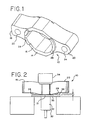
Fig. 2 is a side view of a fuel injector clamp in accordance with a first embodiment of the present invention with a fuel injector inserted in the fuel injector clamp, and -
Fig. 3 is a fuel injector clamp in accordance with a first embodiment of the present invention, with a fuel injector inserted in the fuel injector clamp and wherein the fuel injector clamp is subjected to a downward load. - A method of forming a fuel injector clamp utilizing powder metallurgy techniques is provided. This method comprises the steps of providing a powder metal charge comprising, in percent by weight, 0.6-0.9 carbon, 1.5-3.9 copper, 93.2-97.9 iron, with the balance other elements. The powder metal charge is die compacted to the blank shape of the fuel injector clamp to a density of 7.0-7.1 grams per cubic centimeter. The compacted blank is then pre-sintered at 1500-1600 degrees Fahrenheit, for a period of 15 5 minutes to form a powder metal blank. This powder metal blank is then coated with suitable lubricant such as EBS-WAX (Ethylene Bi-Stearamide). The lubricated powder metal blank is re-compacted to a density of at least 7.3 grams per cubic centimeter and then sintered at about 2050 degrees Fahrenheit for a period of 10 to 30 minutes to form final powder metal blank. The final powder metal blank has a ductility and elongation to allow strain without permanent deformation of at least two percent.
- Referring now to
Fig. 1 , afuel injector clamp 10 is shown in accordance with the first embodiment of the present invention.Fuel injector clamp 10 is comprised of a powder metal made in accordance with the method described above.Fuel injector clamp 10 comprises a generallycylindrical center portion 14 having an opening axially there through.Center portion 14 includes alower surface 16. -
First wing portion 18 extents laterally fromcenter portion 14 and includes anaxial opening 22 extending vertically there through.Fuel injector clamp 10 also includes asecond wing portion 20 extending laterally fromcenter portion 14 in a direction 180 degrees fromfirst wing portion 18.Second wing portion 20 also includes anaxial opening 24 that extends vertically there through. -
Center portion 14 also includeslower surface 16 that itself includes afirst support edge 26 extending downwardly along a portion oflower surface 16 adjacent the intersection offirst wing portion 18 andcenter portion 14. Asecond support edge 28 extends downwardly along a portion oflower surface 16 adjacent the intersection ofsecond wing portion 20 withcenter portion 14. - Referring now to
Fig. 2 andFig. 3 ,fuel injector clamp 20 is seen to receivefuel injector 30.Fuel injector 30 is seen to comprise a generally cylindrical elongated structure having a generally cylindricallower body section 32, a generally cylindricalupper body section 34, and asupport 36 located betweenlower body section 32 andupper body section 34.Upper body section 34 is seen to pass through the opening incenter portion 14 offuel injector clamp 10. - In
Fig. 2 , under an unloaded condition,fuel injector clamp 10 is seen to have alower portion 21 of itscenter portion 14 contactingupper surface 38 offuel injector support 36. Under a no load condition,first support edge 26 andsecond support edge 28 do not contactupper surface 38 offuel injector support 36. As shown inFig. 3 , under a load condition,fuel injector clamp 10 would deform elastically such thatfirst support edge 26 andsecond support edge 28 would move downwardly to engageupper surface 38 offuel injector support 36. Such deformation under load would be elastic and, under a downward force of between 10,000 and 23,300 (2250 & 5250 Lbs) newtons, result in a downward movement offirst support edge 26 andsecond support edge 28 each of between 0.63-1.0 milimeters (0.024-0.040 inches).
Claims (12)
- A method of forming a fuel injector clamp comprising the steps of:providing a powder metal charge comprising, in percent by weight, 0.6-0.9 carbon, 1.5-3.9 copper, 93.2-97.9 iron, with the balance other elements,die compacting the powder metal charge to a density of 7.0-7.1 g/cc, and then pre-sintering at 1500-1600 degrees Fahrenheit to form a powder metal blank,coating the powder metal blank with a suitable lubricant, re-compacting the lubricated powder metal blank to a density of at least 7.3 g/cc and then sintering at about 2050 degrees Fahrenheit to form a final powder metal blank.
- The method of claim 1 wherein the final powder metal blank has a ductility and elongation to allow strain without permanent deformation of at least two percent.
- The method of claim 1 or 2 wherein the pre-sintering at 1500-1600 degrees Fahrenheit is performed for 10 minutes.
- The method of claim 1, 2 or 3 wherein the sintering at about 2050 degrees Fahrenheit is performed for 10 to 30 minutes.
- The method of any preceding claim wherein the lubricant is selected from the group of EBS-WAXES.
- A fuel injector clamp comprised of a compacted, sintered powder metal comprising, by percent weight, 0.6-0.9 carbon, 1.5-3.9 copper, 93.2-97.9 iron, with the balance other elements, having a density of at least 7.3 g/cc,
the fuel injector clamp comprising a unitary structure having a generally cylindrical center portion having a center opening, with a first wing portion extending laterally there from and a second wing portion extending laterally there from at a 180 degree angle from the first wing portion,
the center portion having a lower surface, and a first support edge extending downwardly from the center portion lower surface adjacent the first wing portion,
and a second support edge extending downwardly from the center portion lower surface adjacent the second wing portion,
and the center portion lower surface extending downwardly beyond the first support edge and the second support edge. - The fuel injector clamp of claim 6
wherein when the fuel injector clamp is subjected to a downward load at the first and second wing portions, the first and second support edges move downwardly to a plane even with the center portion lower surface. - The fuel injector clamp of claim 7 wherein the downward load is less than the elastic limit of the fuel injector clamp.
- The fuel injector clamp of any of claims 6 to 8 wherein the fuel injector clamp is installed in an engine, and a fuel injector is placed through the center opening in the center portion of the fuel injector clamp,
the fuel injector including a generally flat support having an upper surface that faces the center portion lower surface of the fuel injector clamp,
wherein when the fuel injector clamp is subjected to a downward load at the first and second wing portions, the first and second support edges move elastically downward to control the fuel injector support upper surface. - The fuel injector clamp of claim 9 wherein the downward load is a force of between 10,000 (2250 Lbs) and 23,300 (5250 Lbs) newtons.
- The fuel injector clamp of claim 9 or 10 wherein the first and second support edges move elastically downward a distance of between 0.63 and 1.0 mm (0.024 - 0.040 in).
- The fuel injector clamp of any of claims 6 to 11 made by the method of any of claims 1 to 5.
Priority Applications (1)
| Application Number | Priority Date | Filing Date | Title |
|---|---|---|---|
| PL11250747T PL2428294T3 (en) | 2010-09-10 | 2011-08-30 | Fuel injector clamp |
Applications Claiming Priority (1)
| Application Number | Priority Date | Filing Date | Title |
|---|---|---|---|
| US12/807,582 US8469003B2 (en) | 2010-09-10 | 2010-09-10 | Fuel injector clamp |
Publications (3)
| Publication Number | Publication Date |
|---|---|
| EP2428294A2 true EP2428294A2 (en) | 2012-03-14 |
| EP2428294A3 EP2428294A3 (en) | 2012-05-16 |
| EP2428294B1 EP2428294B1 (en) | 2016-11-23 |
Family
ID=44651526
Family Applications (1)
| Application Number | Title | Priority Date | Filing Date |
|---|---|---|---|
| EP11250747.0A Not-in-force EP2428294B1 (en) | 2010-09-10 | 2011-08-30 | Fuel injector clamp |
Country Status (11)
| Country | Link |
|---|---|
| US (1) | US8469003B2 (en) |
| EP (1) | EP2428294B1 (en) |
| JP (1) | JP5558416B2 (en) |
| CN (1) | CN102398033B (en) |
| CA (1) | CA2738137C (en) |
| DK (1) | DK2428294T3 (en) |
| EA (1) | EA019822B1 (en) |
| ES (1) | ES2607277T3 (en) |
| HU (1) | HUE031150T2 (en) |
| MX (1) | MX339568B (en) |
| PL (1) | PL2428294T3 (en) |
Cited By (1)
| Publication number | Priority date | Publication date | Assignee | Title |
|---|---|---|---|---|
| WO2018106420A1 (en) * | 2016-12-09 | 2018-06-14 | Caterpillar Inc. | Common rail accumulator clamp |
Families Citing this family (6)
| Publication number | Priority date | Publication date | Assignee | Title |
|---|---|---|---|---|
| US8522754B2 (en) * | 2009-07-01 | 2013-09-03 | International Engine Intellectual Property Company, Llc. | Fuel injector clamp |
| US8469003B2 (en) * | 2010-09-10 | 2013-06-25 | Burgess • Norton Mfg. Co., Inc. | Fuel injector clamp |
| EP2821630A1 (en) * | 2013-07-05 | 2015-01-07 | Delphi International Operations Luxembourg S.à r.l. | High pressure fluid connection |
| EP3353409B1 (en) * | 2015-09-24 | 2021-05-19 | Vitesco Technologies GmbH | Fuel rail assembly and method for manufacturing a fuel rail assembly |
| GB2546500B (en) * | 2016-01-19 | 2019-07-24 | Perkins Engines Co Ltd | Reversible injector clamp |
| US12110855B1 (en) * | 2024-02-26 | 2024-10-08 | Deere & Company | Fuel injector clamp with compound mounting |
Family Cites Families (22)
| Publication number | Priority date | Publication date | Assignee | Title |
|---|---|---|---|---|
| SU822994A1 (en) * | 1979-07-23 | 1981-04-25 | Научно-Исследовательский Институтпорошковой Металлургии Белорусскогоордена Трудового Красного Знамениполитехнического Института | Method of producing iron-based sintered articles |
| US4246877A (en) * | 1979-07-27 | 1981-01-27 | General Motors Corporation | Notched injector hold-down clamp |
| SU872034A1 (en) * | 1979-11-01 | 1981-10-15 | Ростовский На Дону Научно-Исследовательский Институт Технологии Машиностроения | Method of producting injection-nozzle sprayer |
| IN159427B (en) * | 1982-11-27 | 1987-05-16 | Perkins Engines Group | |
| US5080712B1 (en) * | 1990-05-16 | 1996-10-29 | Hoeganaes Corp | Optimized double press-double sinter powder metallurgy method |
| US5566658A (en) * | 1995-04-21 | 1996-10-22 | Cummins Engine Company, Inc. | Clamping load distributor and top stop for a fuel injector |
| JP3499370B2 (en) * | 1996-04-22 | 2004-02-23 | 株式会社日立ユニシアオートモティブ | Sintering cold forging method |
| AU723317B2 (en) * | 1996-05-13 | 2000-08-24 | Gkn Sinter Metals Inc. | Method for preparing high performance ferrous materials |
| US6134786A (en) * | 1999-01-29 | 2000-10-24 | Amsted Industries Incorporated | Method for improvement of involute and lead error in powder metal gears |
| JP4026284B2 (en) * | 1999-08-27 | 2007-12-26 | トヨタ自動車株式会社 | Clamp for mounting fuel injection valve |
| DE10152421A1 (en) * | 2001-10-24 | 2003-06-18 | Bosch Gmbh Robert | fastening device |
| JP4570066B2 (en) * | 2003-07-22 | 2010-10-27 | 日産自動車株式会社 | Method for manufacturing sintered sprocket for silent chain |
| JP4056449B2 (en) * | 2003-09-09 | 2008-03-05 | 本田技研工業株式会社 | Side feed type fuel injection valve mounting structure |
| SE0401041D0 (en) * | 2004-04-21 | 2004-04-21 | Hoeganaes Ab | Sintered metal parts and method of manufacturing thereof |
| US7159570B2 (en) * | 2004-12-03 | 2007-01-09 | Millennium Industries Corp. | Fuel injector retention clip |
| US7360524B2 (en) * | 2004-12-03 | 2008-04-22 | Millenium Industries, Inc. | Fuel injector retention clip |
| JP2006219706A (en) * | 2005-02-09 | 2006-08-24 | Sumitomo Denko Shoketsu Gokin Kk | Heat-treated iron based sintered component and method for producing the same |
| US7334572B1 (en) * | 2007-01-30 | 2008-02-26 | Ford Global Technologies, Llc | System and method for securing fuel injectors |
| US20080193320A1 (en) * | 2007-02-09 | 2008-08-14 | Burgess-Norton, Mfg. Co., Inc. | Manufacture and measuring of automotive components |
| EP2199593B1 (en) * | 2008-12-17 | 2011-06-15 | Magneti Marelli S.p.A. | Method for producing the sealing seat with injection holes of a fuel injector |
| US8522754B2 (en) * | 2009-07-01 | 2013-09-03 | International Engine Intellectual Property Company, Llc. | Fuel injector clamp |
| US8469003B2 (en) * | 2010-09-10 | 2013-06-25 | Burgess • Norton Mfg. Co., Inc. | Fuel injector clamp |
-
2010
- 2010-09-10 US US12/807,582 patent/US8469003B2/en not_active Expired - Fee Related
-
2011
- 2011-04-21 CA CA2738137A patent/CA2738137C/en not_active Expired - Fee Related
- 2011-04-27 MX MX2011004430A patent/MX339568B/en active IP Right Grant
- 2011-05-24 CN CN201110168630.6A patent/CN102398033B/en not_active Expired - Fee Related
- 2011-05-30 JP JP2011120418A patent/JP5558416B2/en not_active Expired - Fee Related
- 2011-06-23 EA EA201100830A patent/EA019822B1/en not_active IP Right Cessation
- 2011-08-30 EP EP11250747.0A patent/EP2428294B1/en not_active Not-in-force
- 2011-08-30 PL PL11250747T patent/PL2428294T3/en unknown
- 2011-08-30 DK DK11250747.0T patent/DK2428294T3/en active
- 2011-08-30 ES ES11250747.0T patent/ES2607277T3/en active Active
- 2011-08-30 HU HUE11250747A patent/HUE031150T2/en unknown
Non-Patent Citations (1)
| Title |
|---|
| None |
Cited By (2)
| Publication number | Priority date | Publication date | Assignee | Title |
|---|---|---|---|---|
| WO2018106420A1 (en) * | 2016-12-09 | 2018-06-14 | Caterpillar Inc. | Common rail accumulator clamp |
| US10378499B2 (en) | 2016-12-09 | 2019-08-13 | Caterpillar Inc. | Common rail accumulator clamp |
Also Published As
| Publication number | Publication date |
|---|---|
| CN102398033B (en) | 2014-09-17 |
| EA201100830A1 (en) | 2012-05-30 |
| DK2428294T3 (en) | 2017-01-16 |
| PL2428294T3 (en) | 2017-04-28 |
| EA019822B1 (en) | 2014-06-30 |
| CA2738137A1 (en) | 2012-03-10 |
| EP2428294B1 (en) | 2016-11-23 |
| JP2012057249A (en) | 2012-03-22 |
| ES2607277T3 (en) | 2017-03-29 |
| MX2011004430A (en) | 2012-03-22 |
| MX339568B (en) | 2016-05-31 |
| HUE031150T2 (en) | 2017-07-28 |
| JP5558416B2 (en) | 2014-07-23 |
| EP2428294A3 (en) | 2012-05-16 |
| CA2738137C (en) | 2013-03-12 |
| US8469003B2 (en) | 2013-06-25 |
| US20120060797A1 (en) | 2012-03-15 |
| CN102398033A (en) | 2012-04-04 |
Similar Documents
| Publication | Publication Date | Title |
|---|---|---|
| CA2738137C (en) | Fuel injector clamp | |
| KR101895141B1 (en) | Assembly of internal combustion engine valve and valve seat | |
| JP5170352B2 (en) | Battery can for secondary battery | |
| US9855591B2 (en) | Method for producing a solid actuator | |
| US9670953B2 (en) | Component with deformable pads | |
| US10562102B2 (en) | Green compact of sintered connecting rod using different kind of powder and method of manufacturing the same | |
| US9816597B2 (en) | Sintered pulley | |
| CN208527792U (en) | A kind of tool structure of tubing cold deformation | |
| US9616498B2 (en) | Method for manufacturing a valve spindle | |
| CA2395952C (en) | Siamese bolt holes in powder metal components | |
| EP2825335B1 (en) | Method for producing a valve | |
| CN108343676A (en) | support cover | |
| EP3088723B1 (en) | Fuel injector | |
| EP1602841A3 (en) | Connecting rod for internal combustion engines | |
| KR102189207B1 (en) | Stepped die | |
| CN201401201Y (en) | Valve springs for diesel engines | |
| KR20180013070A (en) | A method of producing a connecting rod | |
| DE102015202725A1 (en) | Fuel injector and method for producing a piezoelectric element for a fuel injector | |
| EP2636881A1 (en) | Injection nozzle | |
| CN120129787A (en) | Rotary joint, related components and method of manufacturing the same | |
| EP3026253B1 (en) | Fuel injector | |
| CN112692541A (en) | Valve seat ring press-fitting method based on reverse deformation control | |
| JPH0647686B2 (en) | Sizing method for iron-based sintered body |
Legal Events
| Date | Code | Title | Description |
|---|---|---|---|
| AK | Designated contracting states |
Kind code of ref document: A2 Designated state(s): AL AT BE BG CH CY CZ DE DK EE ES FI FR GB GR HR HU IE IS IT LI LT LU LV MC MK MT NL NO PL PT RO RS SE SI SK SM TR |
|
| AX | Request for extension of the european patent |
Extension state: BA ME |
|
| PUAI | Public reference made under article 153(3) epc to a published international application that has entered the european phase |
Free format text: ORIGINAL CODE: 0009012 |
|
| PUAL | Search report despatched |
Free format text: ORIGINAL CODE: 0009013 |
|
| AK | Designated contracting states |
Kind code of ref document: A3 Designated state(s): AL AT BE BG CH CY CZ DE DK EE ES FI FR GB GR HR HU IE IS IT LI LT LU LV MC MK MT NL NO PL PT RO RS SE SI SK SM TR |
|
| AX | Request for extension of the european patent |
Extension state: BA ME |
|
| RIC1 | Information provided on ipc code assigned before grant |
Ipc: C22C 33/02 20060101ALI20120412BHEP Ipc: B22F 3/10 20060101AFI20120412BHEP Ipc: B22F 3/16 20060101ALI20120412BHEP Ipc: F02M 61/16 20060101ALI20120412BHEP Ipc: F02M 61/14 20060101ALI20120412BHEP |
|
| 17P | Request for examination filed |
Effective date: 20120802 |
|
| GRAP | Despatch of communication of intention to grant a patent |
Free format text: ORIGINAL CODE: EPIDOSNIGR1 |
|
| RIC1 | Information provided on ipc code assigned before grant |
Ipc: F02M 61/16 20060101ALI20160630BHEP Ipc: B22F 5/10 20060101ALI20160630BHEP Ipc: B22F 3/16 20060101ALI20160630BHEP Ipc: B22F 3/10 20060101AFI20160630BHEP Ipc: F02M 61/14 20060101ALI20160630BHEP Ipc: C22C 33/02 20060101ALI20160630BHEP |
|
| INTG | Intention to grant announced |
Effective date: 20160720 |
|
| GRAS | Grant fee paid |
Free format text: ORIGINAL CODE: EPIDOSNIGR3 |
|
| GRAA | (expected) grant |
Free format text: ORIGINAL CODE: 0009210 |
|
| AK | Designated contracting states |
Kind code of ref document: B1 Designated state(s): AL AT BE BG CH CY CZ DE DK EE ES FI FR GB GR HR HU IE IS IT LI LT LU LV MC MK MT NL NO PL PT RO RS SE SI SK SM TR |
|
| REG | Reference to a national code |
Ref country code: GB Ref legal event code: FG4D |
|
| REG | Reference to a national code |
Ref country code: CH Ref legal event code: EP |
|
| REG | Reference to a national code |
Ref country code: IE Ref legal event code: FG4D |
|
| REG | Reference to a national code |
Ref country code: AT Ref legal event code: REF Ref document number: 847409 Country of ref document: AT Kind code of ref document: T Effective date: 20161215 |
|
| REG | Reference to a national code |
Ref country code: NL Ref legal event code: FP |
|
| REG | Reference to a national code |
Ref country code: DE Ref legal event code: R096 Ref document number: 602011032651 Country of ref document: DE |
|
| REG | Reference to a national code |
Ref country code: SE Ref legal event code: TRGR |
|
| REG | Reference to a national code |
Ref country code: DK Ref legal event code: T3 Effective date: 20170109 |
|
| REG | Reference to a national code |
Ref country code: NO Ref legal event code: T2 Effective date: 20161123 |
|
| PG25 | Lapsed in a contracting state [announced via postgrant information from national office to epo] |
Ref country code: LV Free format text: LAPSE BECAUSE OF FAILURE TO SUBMIT A TRANSLATION OF THE DESCRIPTION OR TO PAY THE FEE WITHIN THE PRESCRIBED TIME-LIMIT Effective date: 20161123 |
|
| REG | Reference to a national code |
Ref country code: LT Ref legal event code: MG4D |
|
| PG25 | Lapsed in a contracting state [announced via postgrant information from national office to epo] |
Ref country code: LT Free format text: LAPSE BECAUSE OF FAILURE TO SUBMIT A TRANSLATION OF THE DESCRIPTION OR TO PAY THE FEE WITHIN THE PRESCRIBED TIME-LIMIT Effective date: 20161123 |
|
| PG25 | Lapsed in a contracting state [announced via postgrant information from national office to epo] |
Ref country code: PT Free format text: LAPSE BECAUSE OF FAILURE TO SUBMIT A TRANSLATION OF THE DESCRIPTION OR TO PAY THE FEE WITHIN THE PRESCRIBED TIME-LIMIT Effective date: 20170323 Ref country code: HR Free format text: LAPSE BECAUSE OF FAILURE TO SUBMIT A TRANSLATION OF THE DESCRIPTION OR TO PAY THE FEE WITHIN THE PRESCRIBED TIME-LIMIT Effective date: 20161123 Ref country code: RS Free format text: LAPSE BECAUSE OF FAILURE TO SUBMIT A TRANSLATION OF THE DESCRIPTION OR TO PAY THE FEE WITHIN THE PRESCRIBED TIME-LIMIT Effective date: 20161123 |
|
| REG | Reference to a national code |
Ref country code: GR Ref legal event code: EP Ref document number: 20160403242 Country of ref document: GR Effective date: 20170410 |
|
| REG | Reference to a national code |
Ref country code: HU Ref legal event code: AG4A Ref document number: E031150 Country of ref document: HU |
|
| PG25 | Lapsed in a contracting state [announced via postgrant information from national office to epo] |
Ref country code: EE Free format text: LAPSE BECAUSE OF FAILURE TO SUBMIT A TRANSLATION OF THE DESCRIPTION OR TO PAY THE FEE WITHIN THE PRESCRIBED TIME-LIMIT Effective date: 20161123 Ref country code: SK Free format text: LAPSE BECAUSE OF FAILURE TO SUBMIT A TRANSLATION OF THE DESCRIPTION OR TO PAY THE FEE WITHIN THE PRESCRIBED TIME-LIMIT Effective date: 20161123 Ref country code: RO Free format text: LAPSE BECAUSE OF FAILURE TO SUBMIT A TRANSLATION OF THE DESCRIPTION OR TO PAY THE FEE WITHIN THE PRESCRIBED TIME-LIMIT Effective date: 20161123 |
|
| REG | Reference to a national code |
Ref country code: DE Ref legal event code: R097 Ref document number: 602011032651 Country of ref document: DE |
|
| REG | Reference to a national code |
Ref country code: FR Ref legal event code: PLFP Year of fee payment: 7 |
|
| PG25 | Lapsed in a contracting state [announced via postgrant information from national office to epo] |
Ref country code: BG Free format text: LAPSE BECAUSE OF FAILURE TO SUBMIT A TRANSLATION OF THE DESCRIPTION OR TO PAY THE FEE WITHIN THE PRESCRIBED TIME-LIMIT Effective date: 20170223 Ref country code: SM Free format text: LAPSE BECAUSE OF FAILURE TO SUBMIT A TRANSLATION OF THE DESCRIPTION OR TO PAY THE FEE WITHIN THE PRESCRIBED TIME-LIMIT Effective date: 20161123 |
|
| PLBE | No opposition filed within time limit |
Free format text: ORIGINAL CODE: 0009261 |
|
| STAA | Information on the status of an ep patent application or granted ep patent |
Free format text: STATUS: NO OPPOSITION FILED WITHIN TIME LIMIT |
|
| 26N | No opposition filed |
Effective date: 20170824 |
|
| PG25 | Lapsed in a contracting state [announced via postgrant information from national office to epo] |
Ref country code: SI Free format text: LAPSE BECAUSE OF FAILURE TO SUBMIT A TRANSLATION OF THE DESCRIPTION OR TO PAY THE FEE WITHIN THE PRESCRIBED TIME-LIMIT Effective date: 20161123 |
|
| PG25 | Lapsed in a contracting state [announced via postgrant information from national office to epo] |
Ref country code: MC Free format text: LAPSE BECAUSE OF FAILURE TO SUBMIT A TRANSLATION OF THE DESCRIPTION OR TO PAY THE FEE WITHIN THE PRESCRIBED TIME-LIMIT Effective date: 20161123 |
|
| PG25 | Lapsed in a contracting state [announced via postgrant information from national office to epo] |
Ref country code: LU Free format text: LAPSE BECAUSE OF NON-PAYMENT OF DUE FEES Effective date: 20170830 |
|
| REG | Reference to a national code |
Ref country code: FR Ref legal event code: PLFP Year of fee payment: 8 |
|
| PG25 | Lapsed in a contracting state [announced via postgrant information from national office to epo] |
Ref country code: MT Free format text: LAPSE BECAUSE OF NON-PAYMENT OF DUE FEES Effective date: 20170830 |
|
| REG | Reference to a national code |
Ref country code: AT Ref legal event code: UEP Ref document number: 847409 Country of ref document: AT Kind code of ref document: T Effective date: 20161123 |
|
| PG25 | Lapsed in a contracting state [announced via postgrant information from national office to epo] |
Ref country code: CY Free format text: LAPSE BECAUSE OF NON-PAYMENT OF DUE FEES Effective date: 20161123 |
|
| PG25 | Lapsed in a contracting state [announced via postgrant information from national office to epo] |
Ref country code: MK Free format text: LAPSE BECAUSE OF FAILURE TO SUBMIT A TRANSLATION OF THE DESCRIPTION OR TO PAY THE FEE WITHIN THE PRESCRIBED TIME-LIMIT Effective date: 20161123 |
|
| PG25 | Lapsed in a contracting state [announced via postgrant information from national office to epo] |
Ref country code: TR Free format text: LAPSE BECAUSE OF FAILURE TO SUBMIT A TRANSLATION OF THE DESCRIPTION OR TO PAY THE FEE WITHIN THE PRESCRIBED TIME-LIMIT Effective date: 20161123 |
|
| PG25 | Lapsed in a contracting state [announced via postgrant information from national office to epo] |
Ref country code: AL Free format text: LAPSE BECAUSE OF FAILURE TO SUBMIT A TRANSLATION OF THE DESCRIPTION OR TO PAY THE FEE WITHIN THE PRESCRIBED TIME-LIMIT Effective date: 20161123 Ref country code: IS Free format text: LAPSE BECAUSE OF FAILURE TO SUBMIT A TRANSLATION OF THE DESCRIPTION OR TO PAY THE FEE WITHIN THE PRESCRIBED TIME-LIMIT Effective date: 20170323 |
|
| PGFP | Annual fee paid to national office [announced via postgrant information from national office to epo] |
Ref country code: NL Payment date: 20200727 Year of fee payment: 10 |
|
| PGFP | Annual fee paid to national office [announced via postgrant information from national office to epo] |
Ref country code: DE Payment date: 20200721 Year of fee payment: 10 Ref country code: DK Payment date: 20200727 Year of fee payment: 10 Ref country code: FI Payment date: 20200723 Year of fee payment: 10 Ref country code: ES Payment date: 20200901 Year of fee payment: 10 Ref country code: NO Payment date: 20200724 Year of fee payment: 10 Ref country code: IE Payment date: 20200723 Year of fee payment: 10 Ref country code: CZ Payment date: 20200724 Year of fee payment: 10 Ref country code: GR Payment date: 20200723 Year of fee payment: 10 Ref country code: FR Payment date: 20200721 Year of fee payment: 10 Ref country code: GB Payment date: 20200722 Year of fee payment: 10 |
|
| PGFP | Annual fee paid to national office [announced via postgrant information from national office to epo] |
Ref country code: SE Payment date: 20200727 Year of fee payment: 10 Ref country code: PL Payment date: 20200723 Year of fee payment: 10 Ref country code: IT Payment date: 20200721 Year of fee payment: 10 Ref country code: CH Payment date: 20200724 Year of fee payment: 10 Ref country code: AT Payment date: 20200723 Year of fee payment: 10 Ref country code: BE Payment date: 20200724 Year of fee payment: 10 Ref country code: HU Payment date: 20200725 Year of fee payment: 10 |
|
| REG | Reference to a national code |
Ref country code: DE Ref legal event code: R082 Ref document number: 602011032651 Country of ref document: DE |
|
| REG | Reference to a national code |
Ref country code: DE Ref legal event code: R119 Ref document number: 602011032651 Country of ref document: DE |
|
| REG | Reference to a national code |
Ref country code: DK Ref legal event code: EBP Effective date: 20210831 |
|
| REG | Reference to a national code |
Ref country code: FI Ref legal event code: MAE |
|
| REG | Reference to a national code |
Ref country code: NO Ref legal event code: MMEP |
|
| REG | Reference to a national code |
Ref country code: SE Ref legal event code: EUG |
|
| REG | Reference to a national code |
Ref country code: CH Ref legal event code: PL |
|
| REG | Reference to a national code |
Ref country code: NL Ref legal event code: MM Effective date: 20210901 |
|
| REG | Reference to a national code |
Ref country code: AT Ref legal event code: MM01 Ref document number: 847409 Country of ref document: AT Kind code of ref document: T Effective date: 20210830 |
|
| REG | Reference to a national code |
Ref country code: BE Ref legal event code: MM Effective date: 20210831 |
|
| GBPC | Gb: european patent ceased through non-payment of renewal fee |
Effective date: 20210830 |
|
| PG25 | Lapsed in a contracting state [announced via postgrant information from national office to epo] |
Ref country code: LI Free format text: LAPSE BECAUSE OF NON-PAYMENT OF DUE FEES Effective date: 20210831 Ref country code: HU Free format text: LAPSE BECAUSE OF NON-PAYMENT OF DUE FEES Effective date: 20210831 Ref country code: FI Free format text: LAPSE BECAUSE OF NON-PAYMENT OF DUE FEES Effective date: 20210830 Ref country code: CH Free format text: LAPSE BECAUSE OF NON-PAYMENT OF DUE FEES Effective date: 20210831 Ref country code: AT Free format text: LAPSE BECAUSE OF NON-PAYMENT OF DUE FEES Effective date: 20210830 |
|
| PG25 | Lapsed in a contracting state [announced via postgrant information from national office to epo] |
Ref country code: SE Free format text: LAPSE BECAUSE OF NON-PAYMENT OF DUE FEES Effective date: 20210831 Ref country code: NO Free format text: LAPSE BECAUSE OF NON-PAYMENT OF DUE FEES Effective date: 20210831 Ref country code: GR Free format text: LAPSE BECAUSE OF NON-PAYMENT OF DUE FEES Effective date: 20220308 Ref country code: CZ Free format text: LAPSE BECAUSE OF NON-PAYMENT OF DUE FEES Effective date: 20210830 |
|
| PG25 | Lapsed in a contracting state [announced via postgrant information from national office to epo] |
Ref country code: NL Free format text: LAPSE BECAUSE OF NON-PAYMENT OF DUE FEES Effective date: 20210901 |
|
| PG25 | Lapsed in a contracting state [announced via postgrant information from national office to epo] |
Ref country code: IT Free format text: LAPSE BECAUSE OF NON-PAYMENT OF DUE FEES Effective date: 20210830 Ref country code: IE Free format text: LAPSE BECAUSE OF NON-PAYMENT OF DUE FEES Effective date: 20210830 Ref country code: GB Free format text: LAPSE BECAUSE OF NON-PAYMENT OF DUE FEES Effective date: 20210830 Ref country code: FR Free format text: LAPSE BECAUSE OF NON-PAYMENT OF DUE FEES Effective date: 20210831 Ref country code: DK Free format text: LAPSE BECAUSE OF NON-PAYMENT OF DUE FEES Effective date: 20210831 Ref country code: DE Free format text: LAPSE BECAUSE OF NON-PAYMENT OF DUE FEES Effective date: 20220301 Ref country code: BE Free format text: LAPSE BECAUSE OF NON-PAYMENT OF DUE FEES Effective date: 20210831 |
|
| REG | Reference to a national code |
Ref country code: ES Ref legal event code: FD2A Effective date: 20221104 |
|
| PG25 | Lapsed in a contracting state [announced via postgrant information from national office to epo] |
Ref country code: ES Free format text: LAPSE BECAUSE OF NON-PAYMENT OF DUE FEES Effective date: 20210831 |
|
| PG25 | Lapsed in a contracting state [announced via postgrant information from national office to epo] |
Ref country code: PL Free format text: LAPSE BECAUSE OF NON-PAYMENT OF DUE FEES Effective date: 20210830 |