EP2428264A2 - Dehydration systems and methods for removing water from a gas - Google Patents
Dehydration systems and methods for removing water from a gas Download PDFInfo
- Publication number
- EP2428264A2 EP2428264A2 EP11179571A EP11179571A EP2428264A2 EP 2428264 A2 EP2428264 A2 EP 2428264A2 EP 11179571 A EP11179571 A EP 11179571A EP 11179571 A EP11179571 A EP 11179571A EP 2428264 A2 EP2428264 A2 EP 2428264A2
- Authority
- EP
- European Patent Office
- Prior art keywords
- solvent
- gas
- flash
- produce
- semi
- Prior art date
- Legal status (The legal status is an assumption and is not a legal conclusion. Google has not performed a legal analysis and makes no representation as to the accuracy of the status listed.)
- Granted
Links
Images


Classifications
-
- B—PERFORMING OPERATIONS; TRANSPORTING
- B01—PHYSICAL OR CHEMICAL PROCESSES OR APPARATUS IN GENERAL
- B01D—SEPARATION
- B01D53/00—Separation of gases or vapours; Recovering vapours of volatile solvents from gases; Chemical or biological purification of waste gases, e.g. engine exhaust gases, smoke, fumes, flue gases, aerosols
- B01D53/14—Separation of gases or vapours; Recovering vapours of volatile solvents from gases; Chemical or biological purification of waste gases, e.g. engine exhaust gases, smoke, fumes, flue gases, aerosols by absorption
- B01D53/1425—Regeneration of liquid absorbents
-
- B—PERFORMING OPERATIONS; TRANSPORTING
- B01—PHYSICAL OR CHEMICAL PROCESSES OR APPARATUS IN GENERAL
- B01D—SEPARATION
- B01D53/00—Separation of gases or vapours; Recovering vapours of volatile solvents from gases; Chemical or biological purification of waste gases, e.g. engine exhaust gases, smoke, fumes, flue gases, aerosols
- B01D53/26—Drying gases or vapours
- B01D53/263—Drying gases or vapours by absorption
-
- B—PERFORMING OPERATIONS; TRANSPORTING
- B01—PHYSICAL OR CHEMICAL PROCESSES OR APPARATUS IN GENERAL
- B01D—SEPARATION
- B01D2252/00—Absorbents, i.e. solvents and liquid materials for gas absorption
- B01D2252/20—Organic absorbents
- B01D2252/202—Alcohols or their derivatives
- B01D2252/2023—Glycols, diols or their derivatives
- B01D2252/2025—Ethers or esters of alkylene glycols, e.g. ethylene or propylene carbonate
-
- B—PERFORMING OPERATIONS; TRANSPORTING
- B01—PHYSICAL OR CHEMICAL PROCESSES OR APPARATUS IN GENERAL
- B01D—SEPARATION
- B01D2256/00—Main component in the product gas stream after treatment
- B01D2256/22—Carbon dioxide
Definitions
- the embodiments described herein relate generally to a gas dehydration system and, more particularly, to a sub-system within a gas dehydration system in which water is removed from a solvent.
- At least some known integrated gasification combined cycle (IGCC) systems produce carbon dioxide (CO 2 ) while producing synthesis gas, or "syngas.”
- CO 2 produced by the IGCC system can be captured to reduce emissions from the IGCC system.
- the captured CO 2 is typically compressed and dehydrated to meet downstream specifications.
- a key specification value is the water content of the captured CO 2 .
- Dehydration of natural gas from reservoirs has been performed during gas processing using, for example, triethylene glycol (TEG) or diethylene glycol (DEG), as a solvent.
- TAG triethylene glycol
- DEG diethylene glycol
- the solvent must be dehydrated prior to being re-used in the natural gas dehydration system because the water-laden solvent does not efficiently remove water from the natural gas.
- the dehydration capacity of the solvent also increases.
- the term "purity,” as it relates to a solvent refers to an amount of water in the solvent and/or a concentration of the solvent by percent (%) weight. As the purity of the solvent increases, the water concentration of the solvent decreases. Conversely, as the purity of the solvent decreases, the water concentration of the solvent increases.
- dried CO 2 is channeled from a gas exit knock-out drum into a Stahl column (gas stripping column) to dry a solvent.
- a dried solvent produced using the dry CO 2 is usually greater than about 99.0% pure.
- the dry CO 2 is a valuable product stream, and using the dry CO 2 to dry the solvent may reduce the percentage capture of the CO 2 dehydration system.
- a dehydration system in one aspect according to the present invention, includes an absorber configured to produce a dry gas and a rich solvent from a wet gas and from a pure solvent and a flash drum coupled in flow communication with the absorber for receiving the rich solvent discharged from the absorber.
- the flash drum is configured to produce flash gas from the rich solvent.
- the dehydration further includes a reboiler configured to produce a semi-lean solvent from the rich solvent and an inert gas system configured to strip the semi-lean solvent using at least the flash gas to produce the pure solvent.
- an inert gas system for use with a dehydration system.
- the inert gas system includes a stripper configured to produce a stripped solvent from at least a rich solvent and flash gas, wherein the flash gas and the rich solvent are produced in a flash drum, a mixer configured to receive at least the flash gas, a reboiler configured to heat the stripped solvent to produce a semi-lean solvent, and a contacting device coupled to flow communication with the mixer and the reboiler.
- the contacting device is configured to contact the semi-lean solvent from the reboiler with at least the flash gas from the mixer.
- a method for removing water from a gas using a solvent includes channeling the gas with the water into an absorber, channeling a pure solvent into the absorber, and contacting the pure solvent and the gas including the water to produce a rich solvent and a dry gas.
- the method further includes channeling the rich solvent to a flash drum to produce a flash gas, heating the rich solvent to produce a semi-lean solvent, and contacting at least flash gas from the flash drum with the semi-lean solvent to produce the pure solvent.
- the embodiments described herein bring captured carbon dioxide (CO 2 ) into contact with a solvent (also known as a liquid desiccant), such as triethylene glycol (TEG) and/or diethylene glycol (DEG), and flash the solvent to remove any soluble CO 2 . More specifically, a rich solvent is produced when the CO 2 is dried, and then the rich solvent is used to produce flash gas and a semi-lean solvent. The semi-lean solvent passes through a stripper system to generate a lean solvent.
- a solvent also known as a liquid desiccant
- TEG triethylene glycol
- DEG diethylene glycol
- the term “semi-lean” refers to a compound that has less water than a wet or rich compound but more water than a dry or lean compound.
- concentration refers to a compound having less water than a dry and/or lean compound.
- any mixer referred to herein can be a static mixer or an inline mixer.
- water and/or “steam” are referred to herein, it should be understood that a “water” and/or “steam” stream can include more than one phase of H 2 O.
- a “steam” stream can include some water.
- the terms “water” and/or “steam” as used herein refer to the compound H 2 O.
- a typical concentration of glycol achieved at atmospheric conditions is about 99.0% by weight because glycol degrades at temperatures above approximately 400 degrees Fahrenheit (°F).
- a subsequent column of gas stripping is used.
- the embodiments described herein use an inert gas and/or flash gas to strip the glycol to desired conditions, such as to a concentration or purity of more than about 99.0%.
- the flash gas from a low-pressure (LP) flash drum is used, either alone or in combination with an inert gas, such as LP nitrogen supplied from an ASU (air separation unit), a tail gas from a tail gas treatment system, clean syngas from a gas processing unit and/or sour syngas from a gas cooling system, to increase the concentration of the solvent.
- an inert gas such as LP nitrogen supplied from an ASU (air separation unit), a tail gas from a tail gas treatment system, clean syngas from a gas processing unit and/or sour syngas from a gas cooling system
- inline mixing and flashing can also be used to increase the concentration of the solvent.
- the dehydration systems described herein include an absorber in which incoming wet CO 2 is contacted with the solvent to dry the CO 2 .
- the solvent is then heated in a reflux coil by stripper overhead gas and is then channeled to a flash drum wherein any soluble CO 2 is removed from the solvent to produce flash gas and rich solvent.
- This rich solvent is then heated with lean solvent discharged from the stripping column prior to being channeled to the stripper.
- the rich solvent discharged from the stripper is at a maximum concentration of about 99.0% by weight at approximately 1 atmospheric pressure (atm).
- the concentration of the solvent should be above about 99.0%.
- a solvent concentration of approximately 99.7% is used at an absorber pressure of about 300 pounds per square inch absolute (psia) absorber pressure, and a solvent concentration of approximately 99.3% is used at an absorber pressure of about 700 psia.
- the rich solvent is heated to produce a semi-lean solvent, and an external inert gas and/or a flash gas is used in a gas stripping column to produce a lean solvent from the semi-lean solvent.
- an external inert gas and/or a flash gas is used in a gas stripping column to produce a lean solvent from the semi-lean solvent.
- a concentration of approximately 99.7% solvent by weight is achieved by mixing LP nitrogen, for example nitrogen discharged from an air separation unit (ASU), with flash gas discharged from a flash drum, and contacting the mixture with the semi-lean solvent.
- the LP nitrogen and/or the flash gas is used as stripping gas in a Stahl column.
- tail gas that is recycled from a tail gas unit and/or a stream of clean syngas and/or sour syngas is used as the stripping gas in the Stahl column.
- a pure solvent entering the absorber can be passed through a coil inside a vessel attached to the Stahl column before being channeled to an absorber.
- the inert gas and/or flash gas being channeled into the stripper first passes through the vessel, which heats the solvent, and then proceeds into the Stahl column.
- the flash gas and the inert gas are mixed and then injected into a last stage of the stripper to produce a solvent concentration as high as approximately 99.6% by weight.
- a mixer mixes the flash gas, the inert gas, and/or a semi-lean solvent.
- the semi-lean solvent is produced in the stripper.
- the mixture is then flashed at atmospheric pressure to produce a solvent having a concentration of approximately 99.4% by weight.
- an inert gas such as the nitrogen
- the inert gas is used to cool a pure solvent being channeled to an absorber to about 90°F before the inert gas is mixed with the flash gas.
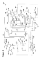
- Fig. 1 is a schematic view of an exemplary dehydration system 100.
- Dehydration system 100 is configured to produce about 99.7% pure solvent for re-use.
- dehydration system 100 includes a gas inlet knock-out (KO) drum 102, an absorber 104, a gas exit KO drum 106, a reflux coil 108, a flash drum 110, a heat exchanger 112, and an inert gas system 200.
- Gas inlet KO drum 102 is coupled in flow communication with a gas inlet 114, absorber 104 and a water discharge 116, and absorber 104 is coupled in flow communication with gas exit KO drum 106, a first mixer 118, and a solvent cooler 130.
- Gas exit KO drum 106 is coupled in flow communication with a gas discharge 122 and first mixer 118.
- First mixer 118 is coupled in flow communication with reflux coil 108.
- Reflux coil 108 is coupled in flow communication with a solvent pressure control device 124, such as a valve and/or a hydroexpander. Reflux coil 108 is configured to heat a rich solvent to just below its decomposition temperature.
- Pressure control device 124 is coupled in flow communication with flash drum 110, which is coupled in flow communication with heat exchanger 112 and inert gas system 200.
- Heat exchanger 112 is coupled in flow communication with inert gas system 200, a solvent pump 136, and solvent cooler 130.
- Inert gas system 200 includes components, described in more detail below, that are in flow communication with a vessel 126, flash drum 110, solvent pump 136, and heat exchanger 112.
- Solvent pump 136 is coupled in flow communication between inert gas system 200 and heat exchanger 112.
- Cooler 130 is coupled in flow communication with heat exchanger 112 and absorber 104.
- vessel 126 is coupled in flow communication with a discharge 138 and a pump 140. More specifically, any liquid collected in vessel 126 is channeled to inert gas system 200 via pump 140.
- inert gas system 200 includes a stripper 202, a reboiler 204, a second mixer 208, and a Stahl column 210.
- Reflux coil 108 is within stripper 202.
- Stripper 202 includes a plurality of inlets 212, 213, 214, and 216 and a plurality of outlets 218 and 220.
- Inlet 212 is coupled in flow communication with heat exchanger 112
- inlet 213 is coupled in flow communication with pump 140
- inlet 214 is coupled in flow communication with Stahl column 210
- inlet 216 is in flow communication with reboiler 204.
- a solvent outlet 218 is coupled in flow communication with reboiler 204, and a gas outlet 220 is coupled in flow communication with vessel 126.
- Reboiler 204 is in flow communication with Stahl column 210, which is considered to be contacting device.
- Stahl column 210 includes a plurality of inlets 222 and 224, a plurality of outlets 228 and 230, and a vessel 226.
- Inlet 222 is coupled in flow communication with reboiler 204
- inlet 224 is coupled in flow communication with second mixer 208.
- Stahl column 210 is coupled in flow communication with inlet 214 of stripper 202 and, at a solvent outlet 230, Stahl column 210 includes vessel 226. Within vessel 226, solvent passed through a coil and exchanges heat with a gas coming into vessel 226. Alternatively, Stahl column 210 does not include vessel 226. In the exemplary embodiment, vessel 226 is coupled in flow communication with pump 136 and second mixer 208. Second mixer 208 is coupled in flow communication with flash drum 110 and an inert gas inlet 232. Alternatively, an inert gas 234 is injected into reboiler 204. In the exemplary embodiment, inert gas inlet 232 is configured to supply inert gas 234 into second mixer 208.
- Inert gas 234 can be, without limitation, nitrogen, tail gas, clean syngas, and/or sour syngas.
- inert gas 234 can be channeled to second mixer 208 from an air separation unit (ASU).
- ASU air separation unit
- the tail gas can be channeled from a tail gas treatment unit, and the syngas can be channeled from a gas clean-up system and/or a gas cooling system.
- gas inlet KO drum 102 receives wet CO 2 142 into dehydration system 100 via gas inlet 114.
- Gas inlet KO drum 102 removes at least some water droplets 144 from wet CO 2 142 to produce wet CO 2 146.
- Wet CO 2 146 enters absorber 104 and mixes with cooled, pure solvent 236.
- Wet solvent 148, carry-over solvent 150, and dry CO 2 152 are produced within absorber 104.
- Wet solvent 148 is channeled from absorber 104 to first mixer 118, and carry-over solvent 150 and dry CO 2 152 are channeled from absorber 104 to gas exit KO drum 106.
- dry CO 2 152 is separated from carry-over solvent 150 and discharged from dehydration system 100 as a product stream.
- Carry-over solvent 150 is channeled from gas exit KO drum 106 to first mixer 118.
- wet solvent 148 and/or carry-over solvent 150 includes CO 2 .
- Any solvent 150 carried over from absorber 104 is knocked out in drum 106 and mixed with rich solvent 148 from absorber 104 within first mixer 118.
- Rich solvent 154 is discharged from first mixer 118. Rich solvent 154 is channeled to reflux coil 108 to be heated. Heated rich solvent 154 is discharged from reflux coil 108 into pressure control device 124.
- Pressure control device 124 is configured to reduce a pressure of heated rich solvent 154 to generate LP rich solvent 154. In a particular embodiment, the pressure of heated rich solvent 154 is decreased from about 800 psia to between about 20 psia and about 90 psia.
- LP rich solvent 154 is then channeled into flash drum 110.
- Flash drum 110 separates gaseous CO 2 rich stream from the liquid solvent and discharges the gaseous CO 2 rich stream as flash gas 156.
- the liquid solvent is discharged as flashed rich solvent 158.
- Flash gas 156 is channeled to second mixer 208, and flashed rich solvent 158 is channeled to heat exchanger 112. From heat exchanger 112, heated flashed rich solvent 158 is channeled to stripper 202. Vapor-liquid mixture 238, overhead 240, and liquid reflux 160 are channeled into stripper 202 to remove water from flashed rich solvent 158 to produce a stripped solvent 162.
- vapor-liquid mixture 238 is channeled from reboiler 204 into stripper 202
- overhead 240 is channeled from Stahl column 210 to stripper 202
- reflux 160 is channeled from vessel 126 into stripper 202.
- Vapor-liquid mixture 238, overhead 240, and reflux 160 produce stripped solvent 162 from heated flashed rich solvent 158.
- stripped solvent 162 is about 99.0% pure.
- Stripped solvent 162 is discharged into reboiler 204 to be heated before being channeled to Stahl column 210. More specifically, reboiler 204 produces a semi-lean solvent 163 from stripped solvent 162 by heating stripped solvent 162.
- overhead gasses 164 from stripper 202 are cooled by solvent 154 in reflux coil 108 and channeled to vessel 126.
- Stripper-off gas 166 is discharged from a top of vessel 126 and reflux 160 is discharged from a bottom of vessel 126.
- reflux 160 is a liquid that has been carried over by gases entering vessel 126.
- Reflux 160 is channeled to pump 140 for circulation through inert gas system 200.
- Stahl column overhead 240 is produced from inert gas 234 and flash gas 156 used in Stahl column 210 and/or steam by-product generated in Stahl column 210. More specifically, flash gas 156 and inert gas 234 are channeled to second mixer 208 and combined therein. Alternatively, inert gas 234 and flash gas 156 are channeled into Stahl column 210 without prior mixing. In the exemplary embodiment, combined gas 242 is channeled through vessel 226 into a bottom of Stahl column 210 to remove water from semi-lean solvent 163 to produce pure solvent 236. In the exemplary embodiment, pure solvent 236 is about 99.5% pure to about 99.7% pure. Overhead 240 is channeled into stripper 202 for use in stripper 202 as described above.
- Pure solvent 236 enters solvent pump 136 where pure solvent 236 is channeled to heat exchanger 112 to be cooled. More specifically, heat exchanger 112 heats solvent 158 from flash drum 110 using pure solvent 236. Pure solvent 236 is then further cooled in cooler 130. More specifically, a cooling fluid 172, such as, but not limited to, inert gas 234 discharged into Stahl column 210 or cooling water, is channeled through cooler 130 to cool pure solvent 236. Pure solvent 236 is then channeled into absorber 104.
- a cooling fluid 172 such as, but not limited to, inert gas 234 discharged into Stahl column 210 or cooling water
- dehydration system 100 includes absorber 104 that produces dry gas 152 and a rich solvent 154 from wet gas 146 and pure solvent 236, flash drum 110 coupled in flow communication with absorber 104 for receiving rich solvent 154, and inert gas system 200 that strips flashed rich solvent 158 using at least flash gas 156. Flash drum 110 produces flash gas 156 and flashed rich solvent 158 from rich solvent 154.
- Dehydration system 100 further includes reflux coil 108 coupled in flow communication between absorber 104 and flash drum 110. Reflux coil 108 heats rich solvent 154 with stripper overhead gas 164.
- Pressure control device 124 is coupled in flow communication between absorber 104 and flash drum 110 to reduce a pressure of rich solvent 154 before rich solvent 154 enters flash drum 110. Heat exchanger 112 heats flashed rich solvent 158 using pure solvent 236.
- inert gas system 200 is alternatively or additionally configured to strip flashed rich solvent 158 using flash gas 156 and/or inert gas 234.
- inert gas 234 is channeled to inert gas system 200 from an ASU.
- inert gas system 200 includes stripper 202 that produces stripped solvent 162 from flashed rich solvent 158, second mixer 208 that receives at least flash gas 156 and channel flash gas 156 to stripper 202, and reboiler 204 that channels vapor-liquid mixture 238 into stripper 202.
- inert gas system 200 includes Stahl column 210 coupled in flow communication between second mixer 208 and stripper 202.
- Overhead gas 240from Stahl column 210 is channeled into stripper 202 after semi-lean solvent 163 has been further concentrated into pure solvent 236 in Stahl column 210 using at least flash gas 156.
- Pure solvent 236 has a concentration of between approximately 99.5% by weight and approximately 99.9% by weight, and more particularly, about 99.7% by weight.
- a method for removing water from a gas using a solvent includes channeling wet gas 146 into absorber 104, channeling pure solvent 236 into absorber 104, and contacting pure solvent 236 and wet 146 to produce rich solvent 154 and dry gas 152.
- Rich solvent 154 is channeled to flash drum 110 to produce flashed rich solvent 158 and flash gas 156, and flashed rich solvent 158 is stripped and heated to produce semi-lean solvent 163.
- At least flash gas 156 is contacted with semi-lean solvent 163 to produce pure solvent 236.
- Contacting at least flash gas 156 with semi-lean solvent 163 can alternatively or additionally include contacting inert gas 234 with semi-lean solvent 163 to produce pure solvent 236.
- Rich solvent 154 can be heated and/or a pressure of rich solvent 154 can be reduced before rich solvent 154 is channeled into flash drum 110.
- contacting at least flash gas 156 with semi-lean solvent 163 includes stripping flashed rich solvent 158 using overhead 240, including at least flash gas 156, to produce stripped solvent 162.
- Stripped solvent 162 is heated to produce semi-lean solvent 163, and at least flash gas 156 is contacted with semi-lean solvent 163 within Stahl column 210 to produce pure solvent 236 having a concentration of at least about 99.5% by weight.
- Fig. 2 is a schematic view of a first alternative dehydration system 300.
- dehydration system 300 includes components that are similar to the components described above with reference to dehydration system 100 (shown in Fig. 1 ). As such, components shown in Fig. 1 are labeled with the same reference numbers used in Fig. 2 .
- dehydration system 300 includes an inert gas system 302 rather than inert gas system 200 (shown in Fig. 1 ). Further, unless otherwise described, inert gas system 302 includes components that are similar to the components described above with reference to inert gas system 200.
- Dehydration system 300 is configured to produce between about 99.4% and about 99.6% pure solvent for re-use.
- inert gas system 302 is similar to inert gas system 200, except inert gas system 302 does not include Stahl column 210 and second mixer 208 is coupled in flow communication with flash drum 110 and stripper 202. More specifically, in dehydration system 300, flash drum 110 separates gaseous CO 2 and/or steam from the liquid solvent and discharges the gaseous CO 2 and/or steam as flash gas 156. The liquid solvent is discharged as flashed rich solvent 158. Flash gas 156 is channeled to second mixer 208, and flashed rich solvent 158 is channeled to heat exchanger 112.
- heated flashed rich solvent 158 is channeled to stripper 202.
- Vapor-liquid mixture 238, combined gas 242, and reflux 160 are channeled into stripper 202 to remove water from flashed rich solvent 158 to produce pure solvent 304. More specifically, vapor-liquid mixture 238 is channeled from reboiler 204 into stripper 202, combined gas 242 is channeled from second mixer 208 to stripper 202, and reflux 160 is channeled from vessel 126 into stripper 202.
- Combined gas 242 is produced by mixing inert gas 234 and flash gas 156 in second mixer 208.
- flash gas 156 and inert gas 234 are channeled to second mixer 208 and combined therein before being channeled into stripper 202.
- inert gas 234 and flash gas 156 are channeled into stripper 202 without prior mixing.
- stripper 202 within stripper 202 vapor-liquid mixture 238, combined gas 242, and reflux 160 produce pure solvent 304 from heated flashed rich solvent 158.
- stripper 202 is considered to be a contacting device.
- pure solvent 304 is about 99.6% pure. Pure solvent 304 is discharged into reboiler 204 to be heated before being channeled to pump 136, and overhead gases 164 are discharged from stripper 202 into vessel 126. Pure solvent 304 enters solvent pump 136 where pure solvent 304 is cooled and channeled into absorber 104.
- Fig. 3 is a schematic view of a second alternative dehydration system 400.
- dehydration system 400 includes components that are similar to the components described above with reference to dehydration system 100 (shown in Fig. 1 ). As such, components shown in Fig. 1 are labeled with the same reference numbers in Fig. 3 .
- dehydration system 400 includes an inert gas system 402 rather than inert gas system 200 (shown in Fig. 1 ). Further, unless otherwise described, inert gas system 402 includes components that are similar to the components described above with reference to inert gas system 200.
- Dehydration system 400 is configured to produce about 99.4% pure solvent for re-use.
- dehydration system 400 is similar to dehydration system 100, except second mixer 208 is also in flow communication with reboiler 204.
- an inert gas system 402 is similar to inert gas system 200, except, rather than including Stahl column 210, inert gas system 402 includes a second flash drum 404, which is considered to be a contacting device.
- reboiler 204 is coupled in flow communication with second mixer 208.
- Second mixer 208 is in further flow communication with flash drum 110, inert gas inlet 232, and second flash drum 404.
- Inert gas inlet 232 is configured to supply an inert gas 234 into second mixer 208.
- inert gas 234 is injected into reboiler 204.
- inert gas 234 can be, without limitation, nitrogen, tail gas, and/or clean syngas.
- inert gas 234 is nitrogen, inert gas 234 can be channeled to second mixer 208 from an air separation unit (ASU).
- ASU air separation unit
- second flash drum 404 is coupled in flow communication with stripper 202 and, at a solvent outlet 408, second flash drum 404 is coupled in flow communication with pump 136.
- second flash drum 404 is an LP flash drum.
- flash drum 110 separates gaseous CO 2 and/or steam from the liquid solvent and discharges the gaseous CO 2 and/or steam as flash gas 156.
- the liquid solvent is discharged as flashed rich solvent 158.
- Flash gas 156 is channeled to second mixer 208, and flashed rich solvent 158 is channeled to heat exchanger 112. From heat exchanger 112, heated flashed rich solvent 158 is channeled to stripper 202.
- Vapor-liquid mixture 238, a gas mixture 412, and reflux 160 are channeled into stripper 202 to remove water from flashed rich solvent 158 to produce stripped solvent 162.
- vapor-liquid mixture 238 is channeled from reboiler 204 into stripper 202
- gas mixture 412 is channeled from second flash drum 404 to stripper 202
- reflux 160 is channeled from vessel 126 into stripper 202.
- Vapor-liquid mixture 238, gas mixture 412, and reflux 160 produce stripped solvent 162 from heated flashed rich solvent 158.
- stripped solvent 162 is about 99.0% pure.
- Stripped solvent 162 is discharged into reboiler 204 to be heated before being channeled to second mixer 208, and overhead gases 164 are discharged from stripper 202 into vessel 126.
- stripped solvent 162 is heated to produce semi-lean solvent 163, which is channeled into second mixer 208.
- Gas mixture 412 is produced from inert gas 234, flash gas 156, and/or steam produced from removing water from semi-lean solvent 163 within second flash drum 404. More specifically, flash gas 156, inert gas 234, and semi-lean solvent 163 are channeled to second mixer 208 and combined therein. Alternatively, inert gas 234, flash gas 156, and/or semi-lean solvent 163 are channeled into second flash drum 404 without prior mixing. In the exemplary embodiment, combined mixture 414 is channeled to second flash drum 404 where water is removed from semi-lean solvent 163 to produce pure solvent 410. In the exemplary embodiment, pure solvent 410 is about 99.4% pure. Pure solvent 410 is discharged into solvent pump 136 and channeled into absorber 104.
- the above-described dehydration systems facilitate producing a higher concentration of solvent to meet dry gas specification values, as compared to known dehydration systems. More specifically, a pressure of the absorber is dependent on a compressor pressure, which is at least partially dependent on flash stage pressures in a flash drum used to dry CO 2 .
- the dehydration system can be run at different absorber pressures.
- the above-described dehydration systems are more efficient than known dehydration systems because heat produced within the system is used to heat other streams within the systems.
- the inert gas systems described herein facilitate minimizing inert gas usage, which generally increases as carbon capture increases.
- the dehydration systems described herein have the ability to meet even lower water specification values for the dried CO 2 than are currently required. Additionally, the dehydration systems described herein enable a product stream from an absorber to be captured without adversely affecting the percentage capture of the system. As such, the value of the product stream is higher as compared to product streams that are re-used for drying a solvent.
- dehydration systems and methods for removing water from a gas are described above in detail.
- the methods and systems are not limited to the specific embodiments described herein, but rather, components of systems and/or steps of the methods may be utilized independently and separately from other components and/or steps described herein.
- the methods may also be used in combination with other dehydration systems and methods, and are not limited to practice with only the integrated gasification combined cycle systems and methods as described herein. Rather, the exemplary embodiment can be implemented and utilized in connection with many other dehydration applications.
Landscapes
- Chemical & Material Sciences (AREA)
- Engineering & Computer Science (AREA)
- Analytical Chemistry (AREA)
- General Chemical & Material Sciences (AREA)
- Oil, Petroleum & Natural Gas (AREA)
- Chemical Kinetics & Catalysis (AREA)
- Gas Separation By Absorption (AREA)
- Treating Waste Gases (AREA)
- Drying Of Gases (AREA)
Abstract
Description
- The embodiments described herein relate generally to a gas dehydration system and, more particularly, to a sub-system within a gas dehydration system in which water is removed from a solvent.
- At least some known integrated gasification combined cycle (IGCC) systems produce carbon dioxide (CO2) while producing synthesis gas, or "syngas." The CO2 produced by the IGCC system can be captured to reduce emissions from the IGCC system. In known IGCC systems, the captured CO2 is typically compressed and dehydrated to meet downstream specifications. A key specification value is the water content of the captured CO2.
- Dehydration of natural gas from reservoirs has been performed during gas processing using, for example, triethylene glycol (TEG) or diethylene glycol (DEG), as a solvent. In such systems, the solvent must be dehydrated prior to being re-used in the natural gas dehydration system because the water-laden solvent does not efficiently remove water from the natural gas. As the purity of a solvent increases, the dehydration capacity of the solvent also increases. As used herein, the term "purity," as it relates to a solvent, refers to an amount of water in the solvent and/or a concentration of the solvent by percent (%) weight. As the purity of the solvent increases, the water concentration of the solvent decreases. Conversely, as the purity of the solvent decreases, the water concentration of the solvent increases.
- In at least one known CO2 dehydration system in an IGCC system, dried CO2 is channeled from a gas exit knock-out drum into a Stahl column (gas stripping column) to dry a solvent. A dried solvent produced using the dry CO2 is usually greater than about 99.0% pure. However, the dry CO2 is a valuable product stream, and using the dry CO2 to dry the solvent may reduce the percentage capture of the CO2 dehydration system.
- In one aspect according to the present invention, a dehydration system is provided. The dehydration system includes an absorber configured to produce a dry gas and a rich solvent from a wet gas and from a pure solvent and a flash drum coupled in flow communication with the absorber for receiving the rich solvent discharged from the absorber. The flash drum is configured to produce flash gas from the rich solvent. The dehydration further includes a reboiler configured to produce a semi-lean solvent from the rich solvent and an inert gas system configured to strip the semi-lean solvent using at least the flash gas to produce the pure solvent.
- In another aspect, an inert gas system for use with a dehydration system is provided. The inert gas system includes a stripper configured to produce a stripped solvent from at least a rich solvent and flash gas, wherein the flash gas and the rich solvent are produced in a flash drum, a mixer configured to receive at least the flash gas, a reboiler configured to heat the stripped solvent to produce a semi-lean solvent, and a contacting device coupled to flow communication with the mixer and the reboiler. The contacting device is configured to contact the semi-lean solvent from the reboiler with at least the flash gas from the mixer.
- In yet another aspect, a method for removing water from a gas using a solvent is provided. The method includes channeling the gas with the water into an absorber, channeling a pure solvent into the absorber, and contacting the pure solvent and the gas including the water to produce a rich solvent and a dry gas. The method further includes channeling the rich solvent to a flash drum to produce a flash gas, heating the rich solvent to produce a semi-lean solvent, and contacting at least flash gas from the flash drum with the semi-lean solvent to produce the pure solvent.
- Various aspects and embodiments of the present invention will now be described in connection with the accompanying drawings, in which:
-
Fig. 1 is a schematic view of an exemplary dehydration system. -
Fig. 2 is a schematic view of a first alternative dehydration system. -
Fig. 3 is a schematic view of a second alternative dehydration system. - The embodiments described herein bring captured carbon dioxide (CO2) into contact with a solvent (also known as a liquid desiccant), such as triethylene glycol (TEG) and/or diethylene glycol (DEG), and flash the solvent to remove any soluble CO2. More specifically, a rich solvent is produced when the CO2 is dried, and then the rich solvent is used to produce flash gas and a semi-lean solvent. The semi-lean solvent passes through a stripper system to generate a lean solvent. As used herein, the terms "wet" and/or "rich" refer to a compound that includes less than about 2% water, and the terms "dry" and/or "lean" refer to a gas and/or a compound that includes less than about 1% water. Further, as used herein, the term "semi-lean" refers to a compound that has less water than a wet or rich compound but more water than a dry or lean compound. Moreover, as used herein, the terms "concentration," "pure," "purity," and/or variations thereof refer to a compound having less water than a dry and/or lean compound. Additionally, any mixer referred to herein can be a static mixer or an inline mixer. Also, although "water" and/or "steam" are referred to herein, it should be understood that a "water" and/or "steam" stream can include more than one phase of H2O. For example, a "steam" stream can include some water. As such, the terms "water" and/or "steam" as used herein refer to the compound H2O.
- A typical concentration of glycol achieved at atmospheric conditions is about 99.0% by weight because glycol degrades at temperatures above approximately 400 degrees Fahrenheit (°F). To further enhance the concentration of the glycol, a subsequent column of gas stripping is used. The embodiments described herein use an inert gas and/or flash gas to strip the glycol to desired conditions, such as to a concentration or purity of more than about 99.0%. More specifically, in one embodiment, the flash gas from a low-pressure (LP) flash drum is used, either alone or in combination with an inert gas, such as LP nitrogen supplied from an ASU (air separation unit), a tail gas from a tail gas treatment system, clean syngas from a gas processing unit and/or sour syngas from a gas cooling system, to increase the concentration of the solvent. Further, inline mixing and flashing can also be used to increase the concentration of the solvent.
- The dehydration systems described herein include an absorber in which incoming wet CO2 is contacted with the solvent to dry the CO2. The solvent is then heated in a reflux coil by stripper overhead gas and is then channeled to a flash drum wherein any soluble CO2 is removed from the solvent to produce flash gas and rich solvent. This rich solvent is then heated with lean solvent discharged from the stripping column prior to being channeled to the stripper. The rich solvent discharged from the stripper is at a maximum concentration of about 99.0% by weight at approximately 1 atmospheric pressure (atm). However, to achieve, for example, 100 PPMV for the dry CO2, the concentration of the solvent should be above about 99.0%. For example, a solvent concentration of approximately 99.7% is used at an absorber pressure of about 300 pounds per square inch absolute (psia) absorber pressure, and a solvent concentration of approximately 99.3% is used at an absorber pressure of about 700 psia.
- To achieve a solvent concentration above approximately 99.0%, the rich solvent is heated to produce a semi-lean solvent, and an external inert gas and/or a flash gas is used in a gas stripping column to produce a lean solvent from the semi-lean solvent. In one embodiment, a concentration of approximately 99.7% solvent by weight is achieved by mixing LP nitrogen, for example nitrogen discharged from an air separation unit (ASU), with flash gas discharged from a flash drum, and contacting the mixture with the semi-lean solvent. The LP nitrogen and/or the flash gas is used as stripping gas in a Stahl column. Additionally or alternatively, tail gas that is recycled from a tail gas unit and/or a stream of clean syngas and/or sour syngas is used as the stripping gas in the Stahl column. Further, a pure solvent entering the absorber can be passed through a coil inside a vessel attached to the Stahl column before being channeled to an absorber. The inert gas and/or flash gas being channeled into the stripper first passes through the vessel, which heats the solvent, and then proceeds into the Stahl column.
- In an alternative embodiment, the flash gas and the inert gas are mixed and then injected into a last stage of the stripper to produce a solvent concentration as high as approximately 99.6% by weight. In still another embodiment, a mixer mixes the flash gas, the inert gas, and/or a semi-lean solvent. The semi-lean solvent is produced in the stripper. The mixture is then flashed at atmospheric pressure to produce a solvent having a concentration of approximately 99.4% by weight. When an inert gas, such as the nitrogen, is mixed with the flash gas, the inert gas is used to cool a pure solvent being channeled to an absorber to about 90°F before the inert gas is mixed with the flash gas.
-
Fig. 1 is a schematic view of anexemplary dehydration system 100.Dehydration system 100 is configured to produce about 99.7% pure solvent for re-use. In the exemplary embodiment,dehydration system 100 includes a gas inlet knock-out (KO)drum 102, anabsorber 104, a gasexit KO drum 106, areflux coil 108, aflash drum 110, aheat exchanger 112, and aninert gas system 200. Gasinlet KO drum 102 is coupled in flow communication with agas inlet 114, absorber 104 and awater discharge 116, and absorber 104 is coupled in flow communication with gasexit KO drum 106, afirst mixer 118, and asolvent cooler 130. Gasexit KO drum 106 is coupled in flow communication with agas discharge 122 andfirst mixer 118.First mixer 118 is coupled in flow communication withreflux coil 108.Reflux coil 108 is coupled in flow communication with a solventpressure control device 124, such as a valve and/or a hydroexpander.Reflux coil 108 is configured to heat a rich solvent to just below its decomposition temperature.Pressure control device 124 is coupled in flow communication withflash drum 110, which is coupled in flow communication withheat exchanger 112 andinert gas system 200.Heat exchanger 112 is coupled in flow communication withinert gas system 200, asolvent pump 136, andsolvent cooler 130. -
Inert gas system 200 includes components, described in more detail below, that are in flow communication with avessel 126,flash drum 110,solvent pump 136, andheat exchanger 112.Solvent pump 136 is coupled in flow communication betweeninert gas system 200 andheat exchanger 112.Cooler 130 is coupled in flow communication withheat exchanger 112 andabsorber 104. Further,vessel 126 is coupled in flow communication with adischarge 138 and apump 140. More specifically, any liquid collected invessel 126 is channeled toinert gas system 200 viapump 140. - In the exemplary embodiment,
inert gas system 200 includes astripper 202, areboiler 204, asecond mixer 208, and aStahl column 210.Reflux coil 108 is withinstripper 202.Stripper 202 includes a plurality ofinlets outlets Inlet 212 is coupled in flow communication withheat exchanger 112,inlet 213 is coupled in flow communication withpump 140, inlet 214 is coupled in flow communication withStahl column 210, andinlet 216 is in flow communication withreboiler 204. Asolvent outlet 218 is coupled in flow communication withreboiler 204, and agas outlet 220 is coupled in flow communication withvessel 126.Reboiler 204 is in flow communication withStahl column 210, which is considered to be contacting device.Stahl column 210 includes a plurality ofinlets outlets vessel 226.Inlet 222 is coupled in flow communication withreboiler 204, andinlet 224 is coupled in flow communication withsecond mixer 208. - At a
gas outlet 228,Stahl column 210 is coupled in flow communication with inlet 214 ofstripper 202 and, at asolvent outlet 230,Stahl column 210 includesvessel 226. Withinvessel 226, solvent passed through a coil and exchanges heat with a gas coming intovessel 226. Alternatively,Stahl column 210 does not includevessel 226. In the exemplary embodiment,vessel 226 is coupled in flow communication withpump 136 andsecond mixer 208.Second mixer 208 is coupled in flow communication withflash drum 110 and aninert gas inlet 232. Alternatively, aninert gas 234 is injected intoreboiler 204. In the exemplary embodiment,inert gas inlet 232 is configured to supplyinert gas 234 intosecond mixer 208.Inert gas 234 can be, without limitation, nitrogen, tail gas, clean syngas, and/or sour syngas. Wheninert gas 234 is nitrogen,inert gas 234 can be channeled tosecond mixer 208 from an air separation unit (ASU). The tail gas can be channeled from a tail gas treatment unit, and the syngas can be channeled from a gas clean-up system and/or a gas cooling system. - During operation of
dehydration system 100, gasinlet KO drum 102 receiveswet CO 2 142 intodehydration system 100 viagas inlet 114. Gasinlet KO drum 102 removes at least somewater droplets 144 fromwet CO 2 142 to producewet CO 2 146.Wet CO 2 146 entersabsorber 104 and mixes with cooled, pure solvent 236. Wet solvent 148, carry-over solvent 150, anddry CO 2 152 are produced withinabsorber 104. Wet solvent 148 is channeled fromabsorber 104 tofirst mixer 118, and carry-over solvent 150 anddry CO 2 152 are channeled fromabsorber 104 to gasexit KO drum 106. Within gasexit KO drum 106,dry CO 2 152 is separated from carry-over solvent 150 and discharged fromdehydration system 100 as a product stream. Carry-over solvent 150 is channeled from gasexit KO drum 106 tofirst mixer 118. In the exemplary embodiment, wet solvent 148 and/or carry-over solvent 150 includes CO2. - Any solvent 150 carried over from
absorber 104 is knocked out indrum 106 and mixed with rich solvent 148 fromabsorber 104 withinfirst mixer 118. Rich solvent 154 is discharged fromfirst mixer 118. Rich solvent 154 is channeled to refluxcoil 108 to be heated. Heated rich solvent 154 is discharged fromreflux coil 108 intopressure control device 124.Pressure control device 124 is configured to reduce a pressure of heated rich solvent 154 to generate LP rich solvent 154. In a particular embodiment, the pressure of heated rich solvent 154 is decreased from about 800 psia to between about 20 psia and about 90 psia. LP rich solvent 154 is then channeled intoflash drum 110. -
Flash drum 110 separates gaseous CO2 rich stream from the liquid solvent and discharges the gaseous CO2 rich stream asflash gas 156. The liquid solvent is discharged as flashed rich solvent 158.Flash gas 156 is channeled tosecond mixer 208, and flashed rich solvent 158 is channeled toheat exchanger 112. Fromheat exchanger 112, heated flashed rich solvent 158 is channeled tostripper 202. Vapor-liquid mixture 238, overhead 240, andliquid reflux 160 are channeled intostripper 202 to remove water from flashed rich solvent 158 to produce a stripped solvent 162. More specifically, vapor-liquid mixture 238 is channeled fromreboiler 204 intostripper 202,overhead 240 is channeled fromStahl column 210 tostripper 202, andreflux 160 is channeled fromvessel 126 intostripper 202. Vapor-liquid mixture 238, overhead 240, and reflux 160 produce stripped solvent 162 from heated flashed rich solvent 158. In one embodiment, stripped solvent 162 is about 99.0% pure. Stripped solvent 162 is discharged intoreboiler 204 to be heated before being channeled toStahl column 210. More specifically,reboiler 204 produces a semi-lean solvent 163 from stripped solvent 162 by heating stripped solvent 162. - In the exemplary embodiment,
overhead gasses 164 fromstripper 202 are cooled by solvent 154 inreflux coil 108 and channeled tovessel 126. Stripper-offgas 166 is discharged from a top ofvessel 126 andreflux 160 is discharged from a bottom ofvessel 126. In one embodiment,reflux 160 is a liquid that has been carried over bygases entering vessel 126.Reflux 160 is channeled to pump 140 for circulation throughinert gas system 200. - Stahl column overhead 240 is produced from
inert gas 234 andflash gas 156 used inStahl column 210 and/or steam by-product generated inStahl column 210. More specifically,flash gas 156 andinert gas 234 are channeled tosecond mixer 208 and combined therein. Alternatively,inert gas 234 andflash gas 156 are channeled intoStahl column 210 without prior mixing. In the exemplary embodiment, combinedgas 242 is channeled throughvessel 226 into a bottom ofStahl column 210 to remove water from semi-lean solvent 163 to produce pure solvent 236. In the exemplary embodiment, pure solvent 236 is about 99.5% pure to about 99.7% pure.Overhead 240 is channeled intostripper 202 for use instripper 202 as described above. Withinvessel 226, heat is exchanged from pure solvent 236 toflash gas 156 and/orinert gas 234. Fromvessel 226, pure solvent 236 is channeled to pump 136. A make-upstream 168 of pure solvent can be added to pure solvent 236 before pure solvent 236 enterspump 136. - Pure solvent 236 enters
solvent pump 136 where pure solvent 236 is channeled toheat exchanger 112 to be cooled. More specifically,heat exchanger 112 heats solvent 158 fromflash drum 110 usingpure solvent 236. Pure solvent 236 is then further cooled in cooler 130. More specifically, a coolingfluid 172, such as, but not limited to,inert gas 234 discharged intoStahl column 210 or cooling water, is channeled through cooler 130 to cool pure solvent 236. Pure solvent 236 is then channeled intoabsorber 104. - In other words,
dehydration system 100 includesabsorber 104 that producesdry gas 152 and a rich solvent 154 fromwet gas 146 and pure solvent 236,flash drum 110 coupled in flow communication withabsorber 104 for receiving rich solvent 154, andinert gas system 200 that strips flashed rich solvent 158 using atleast flash gas 156.Flash drum 110 producesflash gas 156 and flashed rich solvent 158 from rich solvent 154.Dehydration system 100 further includesreflux coil 108 coupled in flow communication betweenabsorber 104 andflash drum 110.Reflux coil 108 heats rich solvent 154 with stripperoverhead gas 164.Pressure control device 124 is coupled in flow communication betweenabsorber 104 andflash drum 110 to reduce a pressure of rich solvent 154 before rich solvent 154 entersflash drum 110.Heat exchanger 112 heats flashed rich solvent 158 usingpure solvent 236. - In the exemplary embodiment,
inert gas system 200 is alternatively or additionally configured to strip flashed rich solvent 158 usingflash gas 156 and/orinert gas 234. Wheninert gas 234 is used withininert gas system 200,inert gas 234 is channeled toinert gas system 200 from an ASU. In the exemplary embodiment,inert gas system 200 includesstripper 202 that produces stripped solvent 162 from flashed rich solvent 158,second mixer 208 that receives atleast flash gas 156 andchannel flash gas 156 tostripper 202, andreboiler 204 that channels vapor-liquid mixture 238 intostripper 202. Further,inert gas system 200 includesStahl column 210 coupled in flow communication betweensecond mixer 208 andstripper 202. Overhead gas240from Stahl column 210 is channeled intostripper 202 after semi-lean solvent 163 has been further concentrated into pure solvent 236 inStahl column 210 using atleast flash gas 156. Pure solvent 236 has a concentration of between approximately 99.5% by weight and approximately 99.9% by weight, and more particularly, about 99.7% by weight. - As such, a method for removing water from a gas using a solvent includes channeling
wet gas 146 intoabsorber 104, channeling pure solvent 236 intoabsorber 104, and contacting pure solvent 236 and wet 146 to produce rich solvent 154 anddry gas 152. Rich solvent 154 is channeled toflash drum 110 to produce flashed rich solvent 158 andflash gas 156, and flashed rich solvent 158 is stripped and heated to produce semi-lean solvent 163. Atleast flash gas 156 is contacted with semi-lean solvent 163 to produce pure solvent 236. Contacting atleast flash gas 156 with semi-lean solvent 163 can alternatively or additionally include contactinginert gas 234 with semi-lean solvent 163 to produce pure solvent 236. Rich solvent 154 can be heated and/or a pressure of rich solvent 154 can be reduced before rich solvent 154 is channeled intoflash drum 110. - In the exemplary embodiment, contacting at
least flash gas 156 with semi-lean solvent 163 includes stripping flashed rich solvent 158 using overhead 240, including atleast flash gas 156, to produce stripped solvent 162. Stripped solvent 162 is heated to produce semi-lean solvent 163, and atleast flash gas 156 is contacted with semi-lean solvent 163 withinStahl column 210 to produce pure solvent 236 having a concentration of at least about 99.5% by weight. -
Fig. 2 is a schematic view of a firstalternative dehydration system 300. Unless otherwise described,dehydration system 300 includes components that are similar to the components described above with reference to dehydration system 100 (shown inFig. 1 ). As such, components shown inFig. 1 are labeled with the same reference numbers used inFig. 2 . In the exemplary embodiment,dehydration system 300 includes aninert gas system 302 rather than inert gas system 200 (shown inFig. 1 ). Further, unless otherwise described,inert gas system 302 includes components that are similar to the components described above with reference toinert gas system 200. -
Dehydration system 300 is configured to produce between about 99.4% and about 99.6% pure solvent for re-use. In the exemplary embodiment,inert gas system 302 is similar toinert gas system 200, exceptinert gas system 302 does not includeStahl column 210 andsecond mixer 208 is coupled in flow communication withflash drum 110 andstripper 202. More specifically, indehydration system 300,flash drum 110 separates gaseous CO2 and/or steam from the liquid solvent and discharges the gaseous CO2 and/or steam asflash gas 156. The liquid solvent is discharged as flashed rich solvent 158.Flash gas 156 is channeled tosecond mixer 208, and flashed rich solvent 158 is channeled toheat exchanger 112. - From
heat exchanger 112, heated flashed rich solvent 158 is channeled tostripper 202. Vapor-liquid mixture 238, combinedgas 242, andreflux 160 are channeled intostripper 202 to remove water from flashed rich solvent 158 to produce pure solvent 304. More specifically, vapor-liquid mixture 238 is channeled fromreboiler 204 intostripper 202, combinedgas 242 is channeled fromsecond mixer 208 tostripper 202, andreflux 160 is channeled fromvessel 126 intostripper 202. Combinedgas 242 is produced by mixinginert gas 234 andflash gas 156 insecond mixer 208. More specifically,flash gas 156 andinert gas 234 are channeled tosecond mixer 208 and combined therein before being channeled intostripper 202. Alternatively,inert gas 234 andflash gas 156 are channeled intostripper 202 without prior mixing. - In the exemplary embodiment, within
stripper 202 vapor-liquid mixture 238, combinedgas 242, and reflux 160 produce pure solvent 304 from heated flashed rich solvent 158. As such,stripper 202 is considered to be a contacting device. In one embodiment, pure solvent 304 is about 99.6% pure. Pure solvent 304 is discharged intoreboiler 204 to be heated before being channeled to pump 136, andoverhead gases 164 are discharged fromstripper 202 intovessel 126. Pure solvent 304 enterssolvent pump 136 where pure solvent 304 is cooled and channeled intoabsorber 104. -
Fig. 3 is a schematic view of a secondalternative dehydration system 400. Unless otherwise described,dehydration system 400 includes components that are similar to the components described above with reference to dehydration system 100 (shown inFig. 1 ). As such, components shown inFig. 1 are labeled with the same reference numbers inFig. 3 . In the exemplary embodiment,dehydration system 400 includes aninert gas system 402 rather than inert gas system 200 (shown inFig. 1 ). Further, unless otherwise described,inert gas system 402 includes components that are similar to the components described above with reference toinert gas system 200. -
Dehydration system 400 is configured to produce about 99.4% pure solvent for re-use. In the exemplary embodiment,dehydration system 400 is similar todehydration system 100, exceptsecond mixer 208 is also in flow communication withreboiler 204. Further, aninert gas system 402 is similar toinert gas system 200, except, rather than includingStahl column 210,inert gas system 402 includes asecond flash drum 404, which is considered to be a contacting device. - More specifically,
reboiler 204 is coupled in flow communication withsecond mixer 208.Second mixer 208 is in further flow communication withflash drum 110,inert gas inlet 232, andsecond flash drum 404.Inert gas inlet 232 is configured to supply aninert gas 234 intosecond mixer 208. Alternatively,inert gas 234 is injected intoreboiler 204. In the exemplary embodiment,inert gas 234 can be, without limitation, nitrogen, tail gas, and/or clean syngas. Wheninert gas 234 is nitrogen,inert gas 234 can be channeled tosecond mixer 208 from an air separation unit (ASU). At agas outlet 406,second flash drum 404 is coupled in flow communication withstripper 202 and, at asolvent outlet 408,second flash drum 404 is coupled in flow communication withpump 136. In the exemplary embodiment,second flash drum 404 is an LP flash drum. - During operation of
dehydration system 400,flash drum 110 separates gaseous CO2 and/or steam from the liquid solvent and discharges the gaseous CO2 and/or steam asflash gas 156. The liquid solvent is discharged as flashed rich solvent 158.Flash gas 156 is channeled tosecond mixer 208, and flashed rich solvent 158 is channeled toheat exchanger 112. Fromheat exchanger 112, heated flashed rich solvent 158 is channeled tostripper 202. Vapor-liquid mixture 238, agas mixture 412, andreflux 160 are channeled intostripper 202 to remove water from flashed rich solvent 158 to produce stripped solvent 162. More specifically, vapor-liquid mixture 238 is channeled fromreboiler 204 intostripper 202,gas mixture 412 is channeled fromsecond flash drum 404 tostripper 202, andreflux 160 is channeled fromvessel 126 intostripper 202. Vapor-liquid mixture 238,gas mixture 412, and reflux 160 produce stripped solvent 162 from heated flashed rich solvent 158. In one embodiment, stripped solvent 162 is about 99.0% pure. Stripped solvent 162 is discharged intoreboiler 204 to be heated before being channeled tosecond mixer 208, andoverhead gases 164 are discharged fromstripper 202 intovessel 126. Withinreboiler 204, stripped solvent 162 is heated to produce semi-lean solvent 163, which is channeled intosecond mixer 208. -
Gas mixture 412 is produced frominert gas 234,flash gas 156, and/or steam produced from removing water from semi-lean solvent 163 withinsecond flash drum 404. More specifically,flash gas 156,inert gas 234, and semi-lean solvent 163 are channeled tosecond mixer 208 and combined therein. Alternatively,inert gas 234,flash gas 156, and/or semi-lean solvent 163 are channeled intosecond flash drum 404 without prior mixing. In the exemplary embodiment, combinedmixture 414 is channeled tosecond flash drum 404 where water is removed from semi-lean solvent 163 to produce pure solvent 410. In the exemplary embodiment, pure solvent 410 is about 99.4% pure. Pure solvent 410 is discharged intosolvent pump 136 and channeled intoabsorber 104. - The above-described dehydration systems facilitate producing a higher concentration of solvent to meet dry gas specification values, as compared to known dehydration systems. More specifically, a pressure of the absorber is dependent on a compressor pressure, which is at least partially dependent on flash stage pressures in a flash drum used to dry CO2. By using the systems and methods described above, the dehydration system can be run at different absorber pressures. Further, the above-described dehydration systems are more efficient than known dehydration systems because heat produced within the system is used to heat other streams within the systems. Moreover, the inert gas systems described herein facilitate minimizing inert gas usage, which generally increases as carbon capture increases. As such, the dehydration systems described herein have the ability to meet even lower water specification values for the dried CO2 than are currently required. Additionally, the dehydration systems described herein enable a product stream from an absorber to be captured without adversely affecting the percentage capture of the system. As such, the value of the product stream is higher as compared to product streams that are re-used for drying a solvent.
- Exemplary embodiments of dehydration systems and methods for removing water from a gas are described above in detail. The methods and systems are not limited to the specific embodiments described herein, but rather, components of systems and/or steps of the methods may be utilized independently and separately from other components and/or steps described herein. For example, the methods may also be used in combination with other dehydration systems and methods, and are not limited to practice with only the integrated gasification combined cycle systems and methods as described herein. Rather, the exemplary embodiment can be implemented and utilized in connection with many other dehydration applications.
- Although specific features of various embodiments of the invention may be shown in some drawings and not in others, this is for convenience only. In accordance with the principles of the invention, any feature of a drawing may be referenced and/or claimed in combination with any feature of any other drawing.
- This written description uses examples to disclose the invention, including the preferred mode, and also to enable any person skilled in the art to practice the invention, including making and using any devices or systems and performing any incorporated methods. The patentable scope of the invention is defined by the claims, and may include other examples that occur to those skilled in the art. Such other examples are intended to be within the scope of the claims if they have structural elements that do not differ from the literal language of the claims, or if they include equivalent structural elements with insubstantial differences from the literal language of the claims.
- Various aspects and embodiments of the present invention are defined by the following numbered clauses:
- 1. A dehydration system comprising:
- an absorber configured to produce a dry gas and a rich solvent from a wet gas and from a pure solvent;
- a flash drum coupled in flow communication with the absorber for receiving the rich solvent discharged from the absorber, the flash drum configured to produce flash gas from the rich solvent;
- a reboiler configured to produce a semi-lean solvent from the rich solvent; and
- an inert gas system configured to strip the semi-lean solvent using at least the flash gas to produce the pure solvent.
- 2. A dehydration system in accordance with
clause 1 wherein the inert gas system is further configured to strip the semi-lean solvent using the flash gas and an inert gas. - 3. A dehydration system in accordance with any preceding clause, wherein the inert gas is channeled to the inert gas system from an air separation unit.
- 4. A dehydration system in accordance with any preceding clause, wherein the inert gas system comprises a stripper configured to produce a stripped solvent from the rich solvent, the stripped solvent channeled to the reboiler to produce the semi-lean solvent, the reboiler further configured to channel a vapor-liquid mixture to the stripper.
- 5. A dehydration system in accordance with any preceding clause, wherein the inert gas system further comprises:
- a Stahl column coupled in flow communication with the reboiler and configured to receive the semi-lean solvent; and
- a mixer configured to receive at least the flash gas and channel the flash gas to the Stahl column, wherein the Stahl column is configured to supply at least the flash gas to the stripper after the semi-lean solvent has been concentrated into the pure solvent using at least the flash gas, the pure solvent having a concentration of between approximately 99.5% by weight and approximately 99.9% by weight.
- 6. A dehydration system in accordance with any preceding clause, wherein the Stahl column comprises a vessel, the pure solvent discharged from the Stahl column passing through the vessel to exchange heat with at least the flash gas.
- 7. A dehydration system in accordance with any preceding clause, wherein the inert gas system further comprises:
- a second flash drum coupled in flow communication with the stripper; and
- a mixer coupled in flow communication with the reboiler and the second flash drum, the second flash drum configured to receive a mixture including at least the stripped solvent and the flash gas from the mixer and to flash the mixture to produce the pure solvent having a concentration of approximately 99.4% by weight.
- 8. A dehydration system in accordance with any preceding clause, further comprising a mixer coupled in flow communication between the flash drum and the stripper, the mixer configured to channel at least the flash gas from the flash drum to the stripper, wherein the pure solvent is the stripped solvent having a concentration of between approximately 99.4% by weight and approximately 99.6% by weight.
- 9. A dehydration system in accordance with any preceding clause, further comprising a pressure control device coupled in flow communication between the absorber and the flash drum, the pressure control device configured to reduce a pressure of the rich solvent before the rich solvent is channeled to the flash drum.
- 10. A dehydration system in accordance with any preceding clause, further comprising a heat exchanger configured to heat the rich solvent using the pure solvent.
- 11. An inert gas system for use with a dehydration system, said inert gas system comprising:
- a stripper configured to produce a stripped solvent from at least a rich solvent and flash gas, the flash gas and the rich solvent produced in a flash drum;
- a mixer configured to receive at least the flash gas;
- a reboiler configured to heat the stripped solvent to produce a semi-lean solvent; and
- a contacting device coupled to flow communication with the mixer and the reboiler, the contacting device configured to contact the semi-lean solvent from the reboiler with at least the flash gas from the mixer.
- 12. An inert gas system in accordance with any preceding clause, wherein the contacting device comprises a Stahl column coupled in flow communication between the mixer and the stripper, the Stahl column configured to supply at least the flash gas to the stripper after the semi-lean solvent has been further concentrated in the Stahl column using at least the flash gas, a further concentrated solvent having a concentration of between approximately 99.5% by weight and approximately 99.9% by weight.
- 13. An inert gas system in accordance with any preceding clause, wherein the contacting device comprises a flash drum coupled in flow communication between the mixer and the stripper, the flash drum configured to receive a mixture including at least the semi-lean solvent and the flash gas discharged from the mixer and flash the mixture to produce a solvent having a concentration of approximately 99.4% by weight.
- 14. An inert gas system in accordance with any preceding clause, wherein the contracting device comprises the stripper, the stripped solvent has a concentration of between approximately 99.4% by weight and approximately 99.6% by weight.
- 15. A method for removing water from a gas using a solvent, said method comprising:
- channeling the gas with the water into an absorber;
- channeling a pure solvent into the absorber;
- contacting the pure solvent and the gas including the water to produce a rich solvent and a dry gas;
- channeling the rich solvent to a flash drum to produce a flash gas;
- heating the rich solvent to produce a semi-lean solvent; and
- contacting at least flash gas from the flash drum with the semi-lean solvent to produce the pure solvent.
- 16. A method in accordance with any preceding clause, wherein contacting at least flash gas from the flash drum with the semi-lean solvent further comprises contacting the flash gas and an inert gas with the semi-lean solvent to produce the pure solvent.
- 17. A method in accordance with any preceding clause, wherein contacting at least flash gas from the flash drum with the semi-lean solvent further comprises:
- stripping the rich solvent to produce a stripped solvent;
- heating the stripped solvent to produce the semi-lean solvent; and
- contacting at least the flash gas and the semi-lean solvent within a Stahl column to produce the pure solvent having a concentration of at least 99.5% by weight.
- 18. A method in accordance with any preceding clause, wherein contacting at least flash gas from the flash drum with the semi-lean solvent further comprises:
- stripping the rich solvent to produce a stripped solvent;
- heating the stripped solvent to produce the semi-lean solvent; and
- flashing at least the flash gas and the semi-lean solvent within a second flash drum to produce the pure solvent having a concentration of at least 99.4% by weight.
- 19. A method in accordance with any preceding clause, wherein contacting at least flash gas from the flash drum with the semi-lean solvent further comprises:
- stripping the rich solvent within a stripper to produce a stripped solvent; and
- contacting at least flash gas with the semi-lean solvent within the stripper to produce the pure solvent having at least a concentration of 99.4% by weight.
- 20. A method in accordance with any preceding clause, further comprising reducing a pressure of the rich solvent before channeling the rich solvent into the flash drum.
Claims (15)
- A dehydration system (100) comprising:an absorber (104) configured to produce a dry gas (152) and a rich solvent (148,154) from a wet gas (146) and from a pure solvent (236);a flash drum (110) coupled in flow communication with the absorber for receiving the rich solvent discharged from the absorber, the flash drum configured to produce flash gas (156) from the rich solvent;a reboiler (204) configured to produce a semi-lean solvent (163) from the rich solvent; andan inert gas system (200) configured to strip the semi-lean solvent using at least the flash gas to produce the pure solvent.
- A dehydration system (100) in accordance with claim 1 wherein the inert gas system (200,302,402) is further configured to strip the semi-lean solvent (163) using the flash gas (156) and an inert gas (234).
- A dehydration system (100) in accordance with any preceding claim, wherein the inert gas (234) is channeled to the inert gas system (200,302,402) from an air separation unit.
- A dehydration system (100) in accordance with any preceding claim, wherein the inert gas system (200,302,402) comprises a stripper (202) configured to produce a stripped solvent (162) from the rich solvent (148,154), the stripped solvent channeled to the reboiler (204) to produce the semi-lean solvent (163), the reboiler further configured to channel a vapor-liquid mixture to the stripper.
- A dehydration system (100) in accordance with any preceding claim, wherein the inert gas system (200,302,402) further comprises:a Stahl column (210) coupled in flow communication with the reboiler (204) and configured to receive the semi-lean solvent (163); anda mixer (118) configured to receive at least the flash gas (156) and channel the flash gas to the Stahl column (210), wherein the Stahl column is configured to supply at least the flash gas to the stripper (202) after the semi-lean solvent (163) has been concentrated into the pure solvent (230) using at least the flash gas, the pure solvent having a concentration of between approximately 99.5% by weight and approximately 99.9% by weight.
- A dehydration system (100) in accordance with any preceding claim, wherein the Stahl olumn (210) comprises a vessel (126), the pure solvent (230) discharged from the Stahl column passing through the vessel to exchange heat with at least the flash gas (156).
- A dehydration system (100) in accordance with any preceding claim, wherein the inert gas system (200,302,402) further comprises:a second flash drum (404) coupled in flow communication with the stripper (202); anda mixer (118) coupled in flow communication with the reboiler (204) and the second flash drum, the second flash drum configured to receive a mixture including at least the stripped solvent (162) and the flash gas (156) from the mixer and to flash the mixture to produce the pure solvent (236) having a concentration of approximately 99.4% by weight.
- A dehydration system (100) in accordance with any preceding claim, further comprising a mixer (118) coupled in flow communication between the flash drum (110) and the stripper (202), the mixer configured to channel at least the flash gas (156) from the flash drum to the stripper, wherein the pure solvent (236) is the stripped solvent (162) having a concentration of between approximately 99.4% by weight and approximately 99.6% by weight.
- A dehydration system (100) in accordance with any preceding claim, further comprising a pressure control device (124) coupled in flow communication between the absorber (104) and the flash drum (110), the pressure control device configured to reduce a pressure of the rich solvent (148,154) before the rich solvent is channeled to the flash drum.
- A dehydration system (100) in accordance with any preceding claim, further comprising a heat exchanger (112) configured to heat the rich solvent (148,154) using the pure solvent (236).
- An inert gas system (200,302,402) for use with a dehydration system (100), said inert gas system comprising:a stripper (202) configured to produce a stripped solvent (162) from at least a rich solvent (148,154) and flash gas (156), the flash gas and the rich solvent produced in a flash drum (110);a mixer (118) configured to receive at least the flash gas;a reboiler (204) configured to heat the stripped solvent to produce a semi-lean solvent (163); anda contacting device coupled to flow communication with the mixer and the reboiler, the contacting device configured to contact the semi-lean solvent from the reboiler with at least the flash gas from the mixer.
- An inert gas system (200,302,402) in accordance with claim 11, wherein the contacting device comprises a Stahl column (210) coupled in flow communication between the mixer (118) and the stripper (202), the Stahl column configured to supply at least the flash gas to the stripper after the semi-lean solvent (163) has been further concentrated in the Stahl column using at least the flash gas, a further concentrated solvent having a concentration of between approximately 99.5% by weight and approximately 99.9% by weight.
- An inert gas system (200,302,402) in accordance with claim 11 or claim 12, wherein the contacting device comprises a flash drum (110) coupled in flow communication between the mixer (118) and the stripper (202), the flash drum configured to receive a mixture including at least the semi-lean solvent (163) and the flash gas (156) discharged from the mixer and flash the mixture to produce a solvent having a concentration of approximately 99.4% by weight.
- An inert gas system (200,302,402) in accordance with any of claims 11 to 13, wherein the contracting device comprises the stripper (202), the stripped solvent (162) has a concentration of between approximately 99.4% by weight and approximately 99.6% by weight.
- A method for removing water from a gas using a solvent, said method comprising:channeling the gas with the water into an absorber (104);channeling a pure solvent (236) into the absorber;contacting the pure solvent and the gas including the water to produce a rich solvent and a dry gas (152);channeling the rich solvent (148,154) to a flash drum to produce a flash gas (156);heating the rich solvent to produce a semi-lean solvent (163); andcontacting at least flash gas from the flash drum (110) with the semi-lean solvent to produce the pure solvent.
Applications Claiming Priority (1)
| Application Number | Priority Date | Filing Date | Title |
|---|---|---|---|
| US12/880,576 US8491712B2 (en) | 2010-09-13 | 2010-09-13 | Dehydration systems and methods for removing water from a gas |
Publications (3)
| Publication Number | Publication Date |
|---|---|
| EP2428264A2 true EP2428264A2 (en) | 2012-03-14 |
| EP2428264A3 EP2428264A3 (en) | 2014-01-08 |
| EP2428264B1 EP2428264B1 (en) | 2017-07-05 |
Family
ID=44582521
Family Applications (1)
| Application Number | Title | Priority Date | Filing Date |
|---|---|---|---|
| EP11179571.2A Active EP2428264B1 (en) | 2010-09-13 | 2011-08-31 | Dehydration system for removing water from a gas |
Country Status (5)
| Country | Link |
|---|---|
| US (1) | US8491712B2 (en) |
| EP (1) | EP2428264B1 (en) |
| CN (1) | CN102397740B (en) |
| AU (1) | AU2011221430B2 (en) |
| CA (1) | CA2751721C (en) |
Cited By (1)
| Publication number | Priority date | Publication date | Assignee | Title |
|---|---|---|---|---|
| EP2724770A1 (en) * | 2012-10-26 | 2014-04-30 | Alstom Technology Ltd | Absorption unit for drying flue gas |
Families Citing this family (9)
| Publication number | Priority date | Publication date | Assignee | Title |
|---|---|---|---|---|
| EP2711335A1 (en) * | 2012-09-24 | 2014-03-26 | Air Products And Chemicals, Inc. | Removal of dissolved gases for boiler feed water preparation |
| CN105399053B (en) * | 2015-12-07 | 2018-01-30 | 南通山剑石墨设备有限公司 | Hydrogen chloride drying system |
| US9944873B1 (en) * | 2016-04-26 | 2018-04-17 | Phil Belveal, Sr. | Add-on system for removing paraffin from a natural gas dehydration system |
| JP6925936B2 (en) * | 2017-10-31 | 2021-08-25 | 三菱重工エンジニアリング株式会社 | Acid gas removal device and acid gas removal method |
| CN111659147B (en) * | 2019-03-08 | 2023-01-13 | 大连佳纯气体净化技术开发有限公司 | Recovery of CO from low-temperature methanol washing process 2 Method and recovery system |
| CN111905567A (en) * | 2019-05-08 | 2020-11-10 | 汪上晓 | Method for regenerating ammonia water after carbon dioxide capture with ammonia water and method for capturing |
| US20230406700A1 (en) | 2020-12-16 | 2023-12-21 | Exxonmobil Chemical Patents Inc. | Processes and Systems for Upgrading a Hydrocarbon-Containing Feed |
| WO2022132369A1 (en) | 2020-12-16 | 2022-06-23 | Exxonmobil Chemical Patents Inc. | Processes and systems for upgrading a hydrocarbon-containing feed |
| US20230036896A1 (en) * | 2021-07-28 | 2023-02-02 | Valence Natural Gas Solutions LLC | Methods and systems for natural gas purification integrated with gas compression |
Family Cites Families (38)
| Publication number | Priority date | Publication date | Assignee | Title |
|---|---|---|---|---|
| US3563696A (en) * | 1969-06-17 | 1971-02-16 | Field And Epes | Separation of co2 and h2s from gas mixtures |
| US4009083A (en) * | 1971-09-02 | 1977-02-22 | The Dow Chemical Company | Regeneration of liquid desiccants and acid gas absorbing liquid desiccants |
| US4010009A (en) * | 1975-11-21 | 1977-03-01 | Phillips Petroleum Company | Glycol regeneration |
| US4332643A (en) | 1976-03-02 | 1982-06-01 | Reid Laurence S | Method of removing water from glycol solutions |
| US4254094A (en) * | 1979-03-19 | 1981-03-03 | Air Products And Chemicals, Inc. | Process for producing hydrogen from synthesis gas containing COS |
| US4280867A (en) | 1979-06-11 | 1981-07-28 | Maloney-Crawford Corporation | Glycol regeneration |
| DE2928934A1 (en) * | 1979-07-18 | 1981-01-29 | Uop Kavag Gmbh | METHOD FOR REGENERATING THE LIQUID ABSORBENT USED IN DRYING A TECHNICAL GAS |
| US4578094A (en) * | 1983-09-14 | 1986-03-25 | El Paso Hydrocarbons | Hydrocarbon separation with a physical solvent |
| US4490985A (en) | 1983-06-29 | 1985-01-01 | General Signal Corporation | Method of dehydrating natural gas |
| DK373686A (en) * | 1985-08-12 | 1987-02-13 | Dow Chemical Co | HOSTING PROCEDURES |
| US5145658A (en) * | 1990-11-28 | 1992-09-08 | Eickmeyer & Associates, Inc. | Reclaiming of heat of reaction energy from an alkaline scrubbing solution used in acid gas removal processes and apparatus therefor |
| US5346537A (en) * | 1992-01-24 | 1994-09-13 | Gas Research Institute | Method and system for controlling emissions from glycol dehydrators |
| US5167675A (en) * | 1992-01-24 | 1992-12-01 | Process Equipment And Service Company, Inc. | Regeneration system for glycol dehydrator |
| US6375806B1 (en) * | 1992-09-11 | 2002-04-23 | Allen Process Systems, L.L.C. | Desiccant reconcentration with control of pollutant gases and vapors |
| FR2698017B1 (en) | 1992-11-19 | 1995-03-10 | Inst Francais Du Petrole | Method for regenerating a liquid desiccant. |
| FR2711650B1 (en) | 1993-10-29 | 1995-12-01 | Elf Aquitaine | Process for the purification of a glycolic solution based on one or more glycols and containing, in addition, water and, as impurities, salts and hydrocarbons. |
| US5725637A (en) | 1994-03-21 | 1998-03-10 | Gas Research Institute | Gas dehydration process |
| US5725636A (en) | 1994-03-21 | 1998-03-10 | Gas Research Institute | Gas dehydration process |
| US5490873A (en) * | 1994-09-12 | 1996-02-13 | Bryan Research & Engineering, Inc. | Hydrocarbon emission reduction |
| US5766423A (en) * | 1995-03-24 | 1998-06-16 | Opc Engineering | Dehydration of gases with liquid desiccants |
| FR2740468B1 (en) * | 1995-10-27 | 1997-12-12 | Inst Francais Du Petrole | PROCESS FOR DRYING GAS WITH GLYCOL INCLUDING PURIFICATION OF GASEOUS DISCHARGES |
| US5882486A (en) | 1996-01-18 | 1999-03-16 | Moore, Jr.; John W. | Glycol refining |
| US5922109A (en) | 1997-03-11 | 1999-07-13 | The Dow Chemical Company | Gas drying process using glycol solution solubility suppressants |
| US5853458A (en) | 1997-04-28 | 1998-12-29 | Gavlin Associates, Inc | Glycol solvents and method thereof |
| FR2771653B1 (en) | 1997-12-02 | 1999-12-31 | Nouvelles Appl Tech | PROCESS FOR DEHYDRATION OF A WET GAS USING A LIQUID DESICCANT, WITH PUSHED REGENERATION OF SAID DESICCANT |
| GB9906717D0 (en) | 1999-03-23 | 1999-05-19 | Norske Stats Oljeselskap | Method and apparatus for drying of natural gas |
| US7531030B2 (en) * | 1999-06-15 | 2009-05-12 | Heath Rodney T | Natural gas dehydrator and system |
| US6177597B1 (en) | 1999-07-06 | 2001-01-23 | Gavlin Associates, Inc. | Glycol solvents and process |
| US6251166B1 (en) * | 1999-08-18 | 2001-06-26 | Anderson Controls, Lc | Glycol regeneration system having a pressurized reboiler to remove BTEX compounds |
| US6896718B2 (en) | 2000-09-12 | 2005-05-24 | Clearwater International Llc | Gas dehydration with cavitation regeneration of potassium formate dehydrating solution |
| US7132008B2 (en) | 2002-10-25 | 2006-11-07 | Membrane Technology & Research, Inc. | Natural gas dehydration apparatus |
| US6789288B2 (en) | 2002-10-25 | 2004-09-14 | Membrane Technology And Research, Inc. | Natural gas dehydration process and apparatus |
| US7597746B2 (en) * | 2002-12-17 | 2009-10-06 | Fluor Technologies Corporation | Configurations and methods for acid gas and contaminant removal with near zero emission |
| NO20031458D0 (en) | 2003-03-28 | 2003-03-28 | Minox Technology As | Gas solidification plant |
| ITMI20042352A1 (en) | 2004-12-10 | 2005-03-10 | Eni Spa | PROCEDURE FOR THE DISASTER OF A GAS |
| US8480982B2 (en) * | 2007-02-22 | 2013-07-09 | Fluor Technologies Corporation | Configurations and methods for carbon dioxide and hydrogen production from gasification streams |
| NO336193B1 (en) * | 2007-09-14 | 2015-06-08 | Aker Engineering & Technology | Improved method of absorbent regeneration |
| US20100281775A1 (en) * | 2009-05-11 | 2010-11-11 | Gly-Tech Services, Inc. | System for dehydrating natural gas |
-
2010
- 2010-09-13 US US12/880,576 patent/US8491712B2/en active Active
-
2011
- 2011-08-31 EP EP11179571.2A patent/EP2428264B1/en active Active
- 2011-09-01 CA CA2751721A patent/CA2751721C/en active Active
- 2011-09-09 AU AU2011221430A patent/AU2011221430B2/en active Active
- 2011-09-13 CN CN201110284375.1A patent/CN102397740B/en active Active
Non-Patent Citations (1)
| Title |
|---|
| None |
Cited By (1)
| Publication number | Priority date | Publication date | Assignee | Title |
|---|---|---|---|---|
| EP2724770A1 (en) * | 2012-10-26 | 2014-04-30 | Alstom Technology Ltd | Absorption unit for drying flue gas |
Also Published As
| Publication number | Publication date |
|---|---|
| US8491712B2 (en) | 2013-07-23 |
| AU2011221430A1 (en) | 2012-03-29 |
| EP2428264A3 (en) | 2014-01-08 |
| CN102397740A (en) | 2012-04-04 |
| EP2428264B1 (en) | 2017-07-05 |
| CA2751721A1 (en) | 2012-03-13 |
| AU2011221430B2 (en) | 2016-07-14 |
| CN102397740B (en) | 2016-03-30 |
| CA2751721C (en) | 2018-08-14 |
| US20120060690A1 (en) | 2012-03-15 |
Similar Documents
| Publication | Publication Date | Title |
|---|---|---|
| CA2751721C (en) | Dehydration systems and methods for removing water from a gas | |
| US7192468B2 (en) | Configurations and method for improved gas removal | |
| US9295940B2 (en) | Configurations and methods for high pressure acid gas removal in the production of ultra-low sulfur gas | |
| CA2774493C (en) | High pressure high co2 removal configurations and methods | |
| AU2002307364C1 (en) | Configurations and methods for improved acid gas removal | |
| JP5036183B2 (en) | Improved solvent use and regeneration | |
| US10641549B2 (en) | Integration methods of gas processing plant and nitrogen rejection unit for high nitrogen feed gases | |
| CN107438475B (en) | Method for energy efficient recovery of carbon dioxide from absorbent and apparatus suitable for operating the method | |
| CN211384447U (en) | A facility for the purification of crude synthesis gas by gas scrubbing with a scrubbing medium | |
| CN107073388B (en) | Regeneration method of energy-efficient solvent for carbon dioxide capture | |
| CN110615404B (en) | Method and apparatus for producing multiple gaseous products from shifted and unshifted crude synthesis gas | |
| US20240335786A1 (en) | Process for separating carbon dioxide from a raw hydrogen product | |
| US9028682B2 (en) | System and method for H2S removal integrated with stinson process CO2 removal | |
| CN107278167B (en) | A method of recovering carbon dioxide from an absorbent with reduced stripping steam supply | |
| GB2464368A (en) | A solvent regeneration process | |
| AU2007201677B2 (en) | Configurations and methods for improved acid gas removal | |
| KR20260012712A (en) | Method and device for separating CO2 by partial condensation and/or distillation |
Legal Events
| Date | Code | Title | Description |
|---|---|---|---|
| AK | Designated contracting states |
Kind code of ref document: A2 Designated state(s): AL AT BE BG CH CY CZ DE DK EE ES FI FR GB GR HR HU IE IS IT LI LT LU LV MC MK MT NL NO PL PT RO RS SE SI SK SM TR |
|
| AX | Request for extension of the european patent |
Extension state: BA ME |
|
| PUAI | Public reference made under article 153(3) epc to a published international application that has entered the european phase |
Free format text: ORIGINAL CODE: 0009012 |
|
| PUAL | Search report despatched |
Free format text: ORIGINAL CODE: 0009013 |
|
| AK | Designated contracting states |
Kind code of ref document: A3 Designated state(s): AL AT BE BG CH CY CZ DE DK EE ES FI FR GB GR HR HU IE IS IT LI LT LU LV MC MK MT NL NO PL PT RO RS SE SI SK SM TR |
|
| AX | Request for extension of the european patent |
Extension state: BA ME |
|
| RIC1 | Information provided on ipc code assigned before grant |
Ipc: B01D 53/26 20060101ALI20131205BHEP Ipc: B01D 53/14 20060101AFI20131205BHEP |
|
| 17P | Request for examination filed |
Effective date: 20140708 |
|
| RBV | Designated contracting states (corrected) |
Designated state(s): AL AT BE BG CH CY CZ DE DK EE ES FI FR GB GR HR HU IE IS IT LI LT LU LV MC MK MT NL NO PL PT RO RS SE SI SK SM TR |
|
| 17Q | First examination report despatched |
Effective date: 20150604 |
|
| GRAP | Despatch of communication of intention to grant a patent |
Free format text: ORIGINAL CODE: EPIDOSNIGR1 |
|
| INTG | Intention to grant announced |
Effective date: 20170201 |
|
| GRAS | Grant fee paid |
Free format text: ORIGINAL CODE: EPIDOSNIGR3 |
|
| GRAA | (expected) grant |
Free format text: ORIGINAL CODE: 0009210 |
|
| AK | Designated contracting states |
Kind code of ref document: B1 Designated state(s): AL AT BE BG CH CY CZ DE DK EE ES FI FR GB GR HR HU IE IS IT LI LT LU LV MC MK MT NL NO PL PT RO RS SE SI SK SM TR |
|
| REG | Reference to a national code |
Ref country code: GB Ref legal event code: FG4D |
|
| REG | Reference to a national code |
Ref country code: CH Ref legal event code: EP |
|
| REG | Reference to a national code |
Ref country code: AT Ref legal event code: REF Ref document number: 906202 Country of ref document: AT Kind code of ref document: T Effective date: 20170715 |
|
| REG | Reference to a national code |
Ref country code: IE Ref legal event code: FG4D |
|
| REG | Reference to a national code |
Ref country code: DE Ref legal event code: R096 Ref document number: 602011039265 Country of ref document: DE |
|
| REG | Reference to a national code |
Ref country code: NL Ref legal event code: FP |
|
| REG | Reference to a national code |
Ref country code: AT Ref legal event code: MK05 Ref document number: 906202 Country of ref document: AT Kind code of ref document: T Effective date: 20170705 |
|
| REG | Reference to a national code |
Ref country code: LT Ref legal event code: MG4D |
|
| PG25 | Lapsed in a contracting state [announced via postgrant information from national office to epo] |
Ref country code: FI Free format text: LAPSE BECAUSE OF FAILURE TO SUBMIT A TRANSLATION OF THE DESCRIPTION OR TO PAY THE FEE WITHIN THE PRESCRIBED TIME-LIMIT Effective date: 20170705 Ref country code: NO Free format text: LAPSE BECAUSE OF FAILURE TO SUBMIT A TRANSLATION OF THE DESCRIPTION OR TO PAY THE FEE WITHIN THE PRESCRIBED TIME-LIMIT Effective date: 20171005 Ref country code: AT Free format text: LAPSE BECAUSE OF FAILURE TO SUBMIT A TRANSLATION OF THE DESCRIPTION OR TO PAY THE FEE WITHIN THE PRESCRIBED TIME-LIMIT Effective date: 20170705 Ref country code: HR Free format text: LAPSE BECAUSE OF FAILURE TO SUBMIT A TRANSLATION OF THE DESCRIPTION OR TO PAY THE FEE WITHIN THE PRESCRIBED TIME-LIMIT Effective date: 20170705 Ref country code: LT Free format text: LAPSE BECAUSE OF FAILURE TO SUBMIT A TRANSLATION OF THE DESCRIPTION OR TO PAY THE FEE WITHIN THE PRESCRIBED TIME-LIMIT Effective date: 20170705 Ref country code: SE Free format text: LAPSE BECAUSE OF FAILURE TO SUBMIT A TRANSLATION OF THE DESCRIPTION OR TO PAY THE FEE WITHIN THE PRESCRIBED TIME-LIMIT Effective date: 20170705 |
|
| PG25 | Lapsed in a contracting state [announced via postgrant information from national office to epo] |
Ref country code: ES Free format text: LAPSE BECAUSE OF FAILURE TO SUBMIT A TRANSLATION OF THE DESCRIPTION OR TO PAY THE FEE WITHIN THE PRESCRIBED TIME-LIMIT Effective date: 20170705 Ref country code: GR Free format text: LAPSE BECAUSE OF FAILURE TO SUBMIT A TRANSLATION OF THE DESCRIPTION OR TO PAY THE FEE WITHIN THE PRESCRIBED TIME-LIMIT Effective date: 20171006 Ref country code: RS Free format text: LAPSE BECAUSE OF FAILURE TO SUBMIT A TRANSLATION OF THE DESCRIPTION OR TO PAY THE FEE WITHIN THE PRESCRIBED TIME-LIMIT Effective date: 20170705 Ref country code: IS Free format text: LAPSE BECAUSE OF FAILURE TO SUBMIT A TRANSLATION OF THE DESCRIPTION OR TO PAY THE FEE WITHIN THE PRESCRIBED TIME-LIMIT Effective date: 20171105 Ref country code: BG Free format text: LAPSE BECAUSE OF FAILURE TO SUBMIT A TRANSLATION OF THE DESCRIPTION OR TO PAY THE FEE WITHIN THE PRESCRIBED TIME-LIMIT Effective date: 20171005 Ref country code: LV Free format text: LAPSE BECAUSE OF FAILURE TO SUBMIT A TRANSLATION OF THE DESCRIPTION OR TO PAY THE FEE WITHIN THE PRESCRIBED TIME-LIMIT Effective date: 20170705 Ref country code: PL Free format text: LAPSE BECAUSE OF FAILURE TO SUBMIT A TRANSLATION OF THE DESCRIPTION OR TO PAY THE FEE WITHIN THE PRESCRIBED TIME-LIMIT Effective date: 20170705 |
|
| REG | Reference to a national code |
Ref country code: CH Ref legal event code: PL |
|
| REG | Reference to a national code |
Ref country code: DE Ref legal event code: R097 Ref document number: 602011039265 Country of ref document: DE |
|
| PG25 | Lapsed in a contracting state [announced via postgrant information from national office to epo] |
Ref country code: LI Free format text: LAPSE BECAUSE OF NON-PAYMENT OF DUE FEES Effective date: 20170831 Ref country code: DK Free format text: LAPSE BECAUSE OF FAILURE TO SUBMIT A TRANSLATION OF THE DESCRIPTION OR TO PAY THE FEE WITHIN THE PRESCRIBED TIME-LIMIT Effective date: 20170705 Ref country code: MC Free format text: LAPSE BECAUSE OF FAILURE TO SUBMIT A TRANSLATION OF THE DESCRIPTION OR TO PAY THE FEE WITHIN THE PRESCRIBED TIME-LIMIT Effective date: 20170705 Ref country code: RO Free format text: LAPSE BECAUSE OF FAILURE TO SUBMIT A TRANSLATION OF THE DESCRIPTION OR TO PAY THE FEE WITHIN THE PRESCRIBED TIME-LIMIT Effective date: 20170705 Ref country code: CZ Free format text: LAPSE BECAUSE OF FAILURE TO SUBMIT A TRANSLATION OF THE DESCRIPTION OR TO PAY THE FEE WITHIN THE PRESCRIBED TIME-LIMIT Effective date: 20170705 Ref country code: CH Free format text: LAPSE BECAUSE OF NON-PAYMENT OF DUE FEES Effective date: 20170831 |
|
| PLBE | No opposition filed within time limit |
Free format text: ORIGINAL CODE: 0009261 |
|
| STAA | Information on the status of an ep patent application or granted ep patent |
Free format text: STATUS: NO OPPOSITION FILED WITHIN TIME LIMIT |
|
| REG | Reference to a national code |
Ref country code: FR Ref legal event code: ST Effective date: 20180430 |
|
| REG | Reference to a national code |
Ref country code: IE Ref legal event code: MM4A |
|
| PG25 | Lapsed in a contracting state [announced via postgrant information from national office to epo] |
Ref country code: IT Free format text: LAPSE BECAUSE OF FAILURE TO SUBMIT A TRANSLATION OF THE DESCRIPTION OR TO PAY THE FEE WITHIN THE PRESCRIBED TIME-LIMIT Effective date: 20170705 Ref country code: SM Free format text: LAPSE BECAUSE OF FAILURE TO SUBMIT A TRANSLATION OF THE DESCRIPTION OR TO PAY THE FEE WITHIN THE PRESCRIBED TIME-LIMIT Effective date: 20170705 Ref country code: SK Free format text: LAPSE BECAUSE OF FAILURE TO SUBMIT A TRANSLATION OF THE DESCRIPTION OR TO PAY THE FEE WITHIN THE PRESCRIBED TIME-LIMIT Effective date: 20170705 Ref country code: EE Free format text: LAPSE BECAUSE OF FAILURE TO SUBMIT A TRANSLATION OF THE DESCRIPTION OR TO PAY THE FEE WITHIN THE PRESCRIBED TIME-LIMIT Effective date: 20170705 |
|
| REG | Reference to a national code |
Ref country code: BE Ref legal event code: MM Effective date: 20170831 |
|
| 26N | No opposition filed |
Effective date: 20180406 |
|
| GBPC | Gb: european patent ceased through non-payment of renewal fee |
Effective date: 20171005 |
|
| PG25 | Lapsed in a contracting state [announced via postgrant information from national office to epo] |
Ref country code: LU Free format text: LAPSE BECAUSE OF NON-PAYMENT OF DUE FEES Effective date: 20170831 |
|
| PG25 | Lapsed in a contracting state [announced via postgrant information from national office to epo] |
Ref country code: IE Free format text: LAPSE BECAUSE OF NON-PAYMENT OF DUE FEES Effective date: 20170831 Ref country code: GB Free format text: LAPSE BECAUSE OF NON-PAYMENT OF DUE FEES Effective date: 20171005 |
|
| PG25 | Lapsed in a contracting state [announced via postgrant information from national office to epo] |
Ref country code: FR Free format text: LAPSE BECAUSE OF NON-PAYMENT OF DUE FEES Effective date: 20170905 Ref country code: SI Free format text: LAPSE BECAUSE OF FAILURE TO SUBMIT A TRANSLATION OF THE DESCRIPTION OR TO PAY THE FEE WITHIN THE PRESCRIBED TIME-LIMIT Effective date: 20170705 Ref country code: BE Free format text: LAPSE BECAUSE OF NON-PAYMENT OF DUE FEES Effective date: 20170831 |
|
| PG25 | Lapsed in a contracting state [announced via postgrant information from national office to epo] |
Ref country code: MT Free format text: LAPSE BECAUSE OF NON-PAYMENT OF DUE FEES Effective date: 20170831 |
|
| PG25 | Lapsed in a contracting state [announced via postgrant information from national office to epo] |
Ref country code: HU Free format text: LAPSE BECAUSE OF FAILURE TO SUBMIT A TRANSLATION OF THE DESCRIPTION OR TO PAY THE FEE WITHIN THE PRESCRIBED TIME-LIMIT; INVALID AB INITIO Effective date: 20110831 |
|
| PG25 | Lapsed in a contracting state [announced via postgrant information from national office to epo] |
Ref country code: CY Free format text: LAPSE BECAUSE OF NON-PAYMENT OF DUE FEES Effective date: 20170705 |
|
| PG25 | Lapsed in a contracting state [announced via postgrant information from national office to epo] |
Ref country code: MK Free format text: LAPSE BECAUSE OF FAILURE TO SUBMIT A TRANSLATION OF THE DESCRIPTION OR TO PAY THE FEE WITHIN THE PRESCRIBED TIME-LIMIT Effective date: 20170705 |
|
| REG | Reference to a national code |
Ref country code: NL Ref legal event code: PD Owner name: AIR PRODUCTS AND CHEMICALS, INC.; US Free format text: DETAILS ASSIGNMENT: CHANGE OF OWNER(S), ASSIGNMENT; FORMER OWNER NAME: GENERAL ELECTRIC COMPANY Effective date: 20200122 |
|
| PG25 | Lapsed in a contracting state [announced via postgrant information from national office to epo] |
Ref country code: TR Free format text: LAPSE BECAUSE OF FAILURE TO SUBMIT A TRANSLATION OF THE DESCRIPTION OR TO PAY THE FEE WITHIN THE PRESCRIBED TIME-LIMIT Effective date: 20170705 |
|
| REG | Reference to a national code |
Ref country code: DE Ref legal event code: R081 Ref document number: 602011039265 Country of ref document: DE Owner name: AIR PRODUCTS AND CHEMICALS, INC., ALLENTOWN, US Free format text: FORMER OWNER: GENERAL ELECTRIC COMPANY, SCHENECTADY, N.Y., US Ref country code: DE Ref legal event code: R081 Ref document number: 602011039265 Country of ref document: DE Owner name: AIR PRODUCTS AND CHEMICALS, INC., ALLENTOWN, US Free format text: FORMER OWNER: GENERAL ELECTRIC COMPANY, SCHENECTADY, NY, US |
|
| PG25 | Lapsed in a contracting state [announced via postgrant information from national office to epo] |
Ref country code: PT Free format text: LAPSE BECAUSE OF FAILURE TO SUBMIT A TRANSLATION OF THE DESCRIPTION OR TO PAY THE FEE WITHIN THE PRESCRIBED TIME-LIMIT Effective date: 20170705 |
|
| PG25 | Lapsed in a contracting state [announced via postgrant information from national office to epo] |
Ref country code: AL Free format text: LAPSE BECAUSE OF FAILURE TO SUBMIT A TRANSLATION OF THE DESCRIPTION OR TO PAY THE FEE WITHIN THE PRESCRIBED TIME-LIMIT Effective date: 20170705 |
|
| PGFP | Annual fee paid to national office [announced via postgrant information from national office to epo] |
Ref country code: NL Payment date: 20200814 Year of fee payment: 10 |
|
| REG | Reference to a national code |
Ref country code: NL Ref legal event code: MM Effective date: 20210901 |
|
| PG25 | Lapsed in a contracting state [announced via postgrant information from national office to epo] |
Ref country code: NL Free format text: LAPSE BECAUSE OF NON-PAYMENT OF DUE FEES Effective date: 20210901 |
|
| P01 | Opt-out of the competence of the unified patent court (upc) registered |
Effective date: 20230515 |
|
| PGFP | Annual fee paid to national office [announced via postgrant information from national office to epo] |
Ref country code: DE Payment date: 20250702 Year of fee payment: 15 |