EP2426998A1 - Wireless network path setting apparatus and method - Google Patents
Wireless network path setting apparatus and method Download PDFInfo
- Publication number
- EP2426998A1 EP2426998A1 EP11179805A EP11179805A EP2426998A1 EP 2426998 A1 EP2426998 A1 EP 2426998A1 EP 11179805 A EP11179805 A EP 11179805A EP 11179805 A EP11179805 A EP 11179805A EP 2426998 A1 EP2426998 A1 EP 2426998A1
- Authority
- EP
- European Patent Office
- Prior art keywords
- wireless network
- network paths
- status
- route
- communication
- Prior art date
- Legal status (The legal status is an assumption and is not a legal conclusion. Google has not performed a legal analysis and makes no representation as to the accuracy of the status listed.)
- Granted
Links
Images


Classifications
-
- H—ELECTRICITY
- H04—ELECTRIC COMMUNICATION TECHNIQUE
- H04W—WIRELESS COMMUNICATION NETWORKS
- H04W40/00—Communication routing or communication path finding
- H04W40/02—Communication route or path selection, e.g. power-based or shortest path routing
- H04W40/22—Communication route or path selection, e.g. power-based or shortest path routing using selective relaying for reaching a BTS [Base Transceiver Station] or an access point
-
- H—ELECTRICITY
- H04—ELECTRIC COMMUNICATION TECHNIQUE
- H04L—TRANSMISSION OF DIGITAL INFORMATION, e.g. TELEGRAPHIC COMMUNICATION
- H04L41/00—Arrangements for maintenance, administration or management of data switching networks, e.g. of packet switching networks
- H04L41/12—Discovery or management of network topologies
-
- H—ELECTRICITY
- H04—ELECTRIC COMMUNICATION TECHNIQUE
- H04L—TRANSMISSION OF DIGITAL INFORMATION, e.g. TELEGRAPHIC COMMUNICATION
- H04L45/00—Routing or path finding of packets in data switching networks
- H04L45/42—Centralised routing
Definitions
- the present invention relates to a wireless network path setting apparatus and method for setting wireless network paths in a field wireless system.
- network paths of a field wireless system are generated dynamically by a system manager which is defined by the ISA100.11a standard.
- a system manager which is defined by the ISA100.11a standard.
- Detailed specifications of a method for generating network paths are not prescribed in the standard, and an implementing party determines a necessary algorithm.
- an algorithm is such as to generate a network on the basis of such parameters as radio wave intensities indicating states of communication between adjoining devices.
- a backbone router (BBR) which is an access point of field devices is located at a level-0 layer and then levels (level 1, 2, ...) of the field devices are determined according to the number of hops.
- the field devices can have one or both of I/O ability and router capability.
- the backbone router can establish a communication route with a device having I/O ability via a device having router capability.
- a communication route can also be established between, for example, devices at the same level if one of them has route capability. This serves to give redundancy to network paths.
- the communication response time can be made shorter as the number of levels (the number of hops) decreases.
- the redundancy of network paths is effective in increasing their reliability, an unduly high degree of redundancy may cause increase in traffic, elongation of communication response times, or an unexpected degree of exhaustion of batteries.
- the level of each field device e.g., the number of hops from the backbone router
- the response time varies depending on the number of hops
- the situation that network paths are not determined uniquely is not preferable for a control loop in which response times should be determined strictly.
- the redundancy of network paths is effective in increasing their reliability in that continuation of a communication is secured, the same problem as mentioned above occurs when it is applied to a control loop because likewise the number of hops is not determined uniquely.
- Exemplary embodiments of the present invention provide a wireless network path setting apparatus and method capable of determining network paths uniquely.
- a wireless network path setting apparatus includes:
- the investigating module may be configured to investigate the communication environment and status of each route on the basis of information stored in advance and indicating the communication environments and statuses of the respective routes.
- the investigating module may be configured to investigate the communication environment and status of each route on the basis of a result of a trial communication.
- the wireless network paths may have a layered structure.
- the wireless network paths may constitute a control loop.
- a wireless network path setting method includes:
- input wireless network paths are registered as network paths to be used in a field wireless system if the communication environment and status of each route is investigated as appropriate. Therefore network paths can be determined uniquely.
- input wireless network paths are registered as network paths to be used in a field wireless system if the communication environment and status of each route is investigated as appropriate. Therefore, network paths can be determined uniquely.
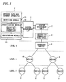
- Fig. 1 is a block diagram showing the configuration of the network path setting apparatus according to the embodiment.
- the network path setting apparatus includes a network path management apparatus 1, a system management unit 2, a system management interface 3, and an ISA100.11a communication stack 4.
- the network path management apparatus 1 receives a user operation and displays various kinds of information relating to network paths.
- the system management unit 2 functions as a system manager as defmed in the ISA100.11a standard.
- the system management interface 3 functions as a communication interface between the network path management apparatus 1 and the system management unit 2.
- the ISA100.11a communication stack 4 is disposed between a backbone router 5 and the system management unit 2.
- the network path management apparatus 1 includes a receiving module 11, an investigating module 12, and a registering module 13.
- the receiving module 11 receives input of wireless network paths.
- the investigating module 12 investigates a communication environment and status of each of routes constituting the wireless network paths that have been input through the receiving module 11.
- the registering module 13 registers the wireless network paths that have been input through the receiving module 11 as network paths to be used in the field wireless system if the communication environment and status of each route investigated by the investigating module 2 is appropriate.
- the backbone router 5 and field devices 6 constitute wireless communication network paths having a layered structure.
- the backbone router 5 is located at level 0 which is the highest layer, and the field devices 6 are located at levels 1,2, ... which are lower layers.
- positions, on the network paths, assigned to the individual devices are ones specified by the user.
- Fig. 2 is a flowchart of a process of operation which is executed by the network path setting apparatus according to the embodiment.
- the network path management apparatus 1 receives network paths (network path topology) specified by the user via the receiving module 11.
- the positions of the backbone router 5 and the field devices 6 are determined uniquely by the network paths specified by the user.
- network path management apparatus 1 investigates a communication environment and status of each of routes constituting the network paths that were received at step S1, by the investigating module 12.
- the investigating module 12 performs investigation on the basis of stored route information (see Fig. 1 ) which is indicating the communication environments and statues of the respective routes.
- the route information includes information relating to a communication environment and status of each route between the backbone router 5 and a field device 6 and each route between field devices 6.
- the route information includes information indicating whether or not each route is provided with a communication function, that is, information indicating whether at least one communication device of each route is the backbone router 5 or a field device 6 having router capability.
- the route information also includes information indicating a distance between the two devices constituting each route and information indicating presence/absence of an obstruction between the two devices constituting each route. For example, these pieces of information may be either input by the user by operating the network path management apparatus 1 or acquired from a database or the like of the field wireless system.
- the route information may include an actual communication environment and status of each route between the backbone router 5 and a field device 6 and each route between field devices 6.
- a communication environment and status represented by such parameters as communication possibility, radio wave intensity, and a communication loss ratio can be acquired by performing a trial communication along each route between the backbone router 5 and a field device 6 or each route between field devices 6 under the control of the system management unit 2.
- the communication loss ratio is a ratio of the number of communication frames (packets) that cannot reach a destination normally (or are lost during transmission) to the number of all packets.
- the acquired communication environments and statuses are transferred to the network path management apparatus 1 via the system management unit 2 and the system management interface 3 and stored there as route information.
- step S1 actual communication environments and statuses can be acquired when network paths specified by the user have been received via the receiving module 11 of the network path management apparatus 1 (step S1), that is, they can be acquired by part of the processing executed at step S2. Actual communication environments and statuses can thus be acquired when network paths pave been input and used in the investigation performed by the investigating module 12.
- step S3 it is judged whether the network paths received at step S1 are applicable or not on the basis of results of the investigation performed at step S2.
- An affirmative judgment is made if the communication environment and status of every route between the backbone router 5 and a field device 6 and every route between field devices 6 is appropriate.
- conditions for a judgment that the communication environment and status of a route is appropriate are that the distance between the two devices constituting the route is shorter than a certain distance, that no obstruction exists between the two devices, that the radio wave intensity of a communication between the two devices is higher than or equal to a certain value, or that the communication loss ratio is smaller than a certain value.
- Fig. 3 shows example results of the investigation performed by the investigating module 12.
- a negative judgment is made at step S3 if as shown in Fig. 3 a communication failure is found at a location 7 which is one of the routes constituting the input network paths.
- An affirmative judgment is made at step S3 if the communication environment and status of every route is good.
- step S3 If an affirmative judgment is made at step S3, the process moves to step S4. On the other hand, if a negative judgment is made at step S3, the process moves to step S5.
- the network paths that were input at step S1 are registered as route information.
- the process is thereafter finished.
- the registered network paths are transferred to the system management unit 2 via the system management interface 3 with proper timing and are employed as a topology of network paths that connect the backbone router 5 and the field devices 6 by the system management unit 2. In this manner, the network path topology as specified by the user can be realized.
- step S5 a communication environment(s) and status(es) are displayed on the network path management apparatus 1. The process is thereafter finished.
- step S5 a route(s) having an inappropriate communication environment and status between devices is displayed.
- the network paths that were input at step S1 are neither registered as route information and nor employed as a topology of network paths that connect the backbone router 5 and the field devices 6.
- the communication environments and statuses of the individual routes may be displayed in such a manner that the network paths are display graphically and the communication environments and statuses of the individual routes are indicated there.
- the communication environment and status of each route may be indicated by a line kind or a display color of a line representing the route.
- the communication environments and statuses of the individual routes constituting the network paths may be displayed in the form of a list.
- the user specifies network paths. If the communication environment and status of each route of the network paths has no problem, the user-specified network paths are employed as an actual network path topology. Therefore, a network path topology is determined uniquely and no trouble occurs in control even in the case where the network is used as a control loop. Furthermore, communication environments and statuses of network paths specified by the user are investigated, and the user-specified network paths are not constructed if an inappropriate communication environment and status is found. Therefore, occurrence of a communication abnormality in the network paths can be prevented.
- the application range of the invention is not limited to the above embodiment.
- the invention can broadly be applied to network path setting apparatus etc. which set wireless network paths in a field wireless system. While certain embodiments have been described, these embodiments have been presented by way of example only, and are not intended to limit the scope of the invention. Indeed, the novel apparatus and method described herein may be embodied in a variety of other forms; furthermore, various omissions, substitutions and changes in the form of the apparatus and method, described herein may be made without departing from the sprit of the invention. The accompanying claims and their equivalents are intended to cover such forms or modifications as would fall within the scope and sprit of the invention.
Landscapes
- Engineering & Computer Science (AREA)
- Computer Networks & Wireless Communication (AREA)
- Signal Processing (AREA)
- Mobile Radio Communication Systems (AREA)
- Data Exchanges In Wide-Area Networks (AREA)
- Telephonic Communication Services (AREA)
Abstract
Description
- The present invention relates to a wireless network path setting apparatus and method for setting wireless network paths in a field wireless system.
- Usually, network paths of a field wireless system are generated dynamically by a system manager which is defined by the ISA100.11a standard. Detailed specifications of a method for generating network paths are not prescribed in the standard, and an implementing party determines a necessary algorithm. For example, an algorithm is such as to generate a network on the basis of such parameters as radio wave intensities indicating states of communication between adjoining devices. In this case, a backbone router (BBR) which is an access point of field devices is located at a level-0 layer and then levels (
level - In such network paths, the communication response time can be made shorter as the number of levels (the number of hops) decreases. On the other band, although the redundancy of network paths is effective in increasing their reliability, an unduly high degree of redundancy may cause increase in traffic, elongation of communication response times, or an unexpected degree of exhaustion of batteries.
- [Patent document 1]
JP-A-2006-318148 - Where network paths are generated according to an algorithm in the above-described manner, the level of each field device (e.g., the number of hops from the backbone router) becomes indefinite. Since the response time varies depending on the number of hops, the situation that network paths are not determined uniquely is not preferable for a control loop in which response times should be determined strictly. Although the redundancy of network paths is effective in increasing their reliability in that continuation of a communication is secured, the same problem as mentioned above occurs when it is applied to a control loop because likewise the number of hops is not determined uniquely.
- Exemplary embodiments of the present invention provide a wireless network path setting apparatus and method capable of determining network paths uniquely.
- A wireless network path setting apparatus according to an exemplary embodiment, includes:
- a receiving module configured to receive input of wireless network paths;
- an investigating module configured to investigate a communication environment and status of each of routes constituting the wireless network paths that have been input through the receiving module; and
- a registering module configured to register the wireless network paths that have been input through the receiving module as network paths to be used in a field wireless system if the communication environment and status of each route investigated by the investigating module is appropriate.
- The investigating module may be configured to investigate the communication environment and status of each route on the basis of information stored in advance and indicating the communication environments and statuses of the respective routes.
- The investigating module may be configured to investigate the communication environment and status of each route on the basis of a result of a trial communication.
- The wireless network paths may have a layered structure.
- The wireless network paths may constitute a control loop.
- A wireless network path setting method according to an exemplary embodiment, includes:
- receiving input of wireless network paths;
- investigating a communication environment and status of each of routes constituting the wireless network paths that have been input; and
- registering the wireless network paths that have been input as network paths to be used in a field wireless system if the communication environment and status of each route investigated is appropriate.
- In the wireless network path setting apparatus according to the embodiment, input wireless network paths are registered as network paths to be used in a field wireless system if the communication environment and status of each route is investigated as appropriate. Therefore network paths can be determined uniquely.
- In the wireless network path setting method according to the embodiment, input wireless network paths are registered as network paths to be used in a field wireless system if the communication environment and status of each route is investigated as appropriate. Therefore, network paths can be determined uniquely.
-
-
Fig. 1 is a block diagram showing the configuration of a network path setting apparatus according to an embodiment. -
Fig. 2 is a flowchart showing of a process of operation which is executed by the network path setting apparatus according to the embodiment. -
Fig. 3 shows example results of investigation performed by an investigatingmodule 12. - An embodiment in which a network path setting apparatus according to the present invention is applied to a field wireless system will be described below.
-
Fig. 1 is a block diagram showing the configuration of the network path setting apparatus according to the embodiment. - As shown in
Fig. 1 , the network path setting apparatus according to the embodiment includes a networkpath management apparatus 1, asystem management unit 2, asystem management interface 3, and an ISA100.11a communication stack 4. The networkpath management apparatus 1 receives a user operation and displays various kinds of information relating to network paths. Thesystem management unit 2 functions as a system manager as defmed in the ISA100.11a standard. Thesystem management interface 3 functions as a communication interface between the networkpath management apparatus 1 and thesystem management unit 2. The ISA100.11a communication stack 4 is disposed between abackbone router 5 and thesystem management unit 2. - As shown in
Fig. 1 , the networkpath management apparatus 1 includes areceiving module 11, an investigatingmodule 12, and aregistering module 13. The receivingmodule 11 receives input of wireless network paths. The investigatingmodule 12 investigates a communication environment and status of each of routes constituting the wireless network paths that have been input through the receivingmodule 11. The registeringmodule 13 registers the wireless network paths that have been input through the receivingmodule 11 as network paths to be used in the field wireless system if the communication environment and status of each route investigated by the investigatingmodule 2 is appropriate. - As shown in
Fig. 1 , thebackbone router 5 andfield devices 6 constitute wireless communication network paths having a layered structure. Thebackbone router 5 is located at level 0 which is the highest layer, and thefield devices 6 are located atlevels - Next, a description will be made of how the network path setting apparatus according to the embodiment operates.
-
Fig. 2 is a flowchart of a process of operation which is executed by the network path setting apparatus according to the embodiment. - Referring to
Fig. 2 , at step S1, the networkpath management apparatus 1 receives network paths (network path topology) specified by the user via thereceiving module 11. The positions of thebackbone router 5 and thefield devices 6 are determined uniquely by the network paths specified by the user. - At step S2, network
path management apparatus 1 investigates a communication environment and status of each of routes constituting the network paths that were received at step S1, by the investigatingmodule 12. - The investigating
module 12 performs investigation on the basis of stored route information (seeFig. 1 ) which is indicating the communication environments and statues of the respective routes. The route information includes information relating to a communication environment and status of each route between thebackbone router 5 and afield device 6 and each route betweenfield devices 6. For example, the route information includes information indicating whether or not each route is provided with a communication function, that is, information indicating whether at least one communication device of each route is thebackbone router 5 or afield device 6 having router capability. The route information also includes information indicating a distance between the two devices constituting each route and information indicating presence/absence of an obstruction between the two devices constituting each route. For example, these pieces of information may be either input by the user by operating the networkpath management apparatus 1 or acquired from a database or the like of the field wireless system. - The route information may include an actual communication environment and status of each route between the
backbone router 5 and afield device 6 and each route betweenfield devices 6. In this case, a communication environment and status represented by such parameters as communication possibility, radio wave intensity, and a communication loss ratio can be acquired by performing a trial communication along each route between thebackbone router 5 and afield device 6 or each route betweenfield devices 6 under the control of thesystem management unit 2. The communication loss ratio is a ratio of the number of communication frames (packets) that cannot reach a destination normally (or are lost during transmission) to the number of all packets. The acquired communication environments and statuses are transferred to the networkpath management apparatus 1 via thesystem management unit 2 and thesystem management interface 3 and stored there as route information. In this manner, actual communication environments and statuses can be acquired when network paths specified by the user have been received via the receivingmodule 11 of the network path management apparatus 1 (step S1), that is, they can be acquired by part of the processing executed at step S2. Actual communication environments and statuses can thus be acquired when network paths pave been input and used in the investigation performed by the investigatingmodule 12. - At step S3, it is judged whether the network paths received at step S1 are applicable or not on the basis of results of the investigation performed at step S2. An affirmative judgment is made if the communication environment and status of every route between the
backbone router 5 and afield device 6 and every route betweenfield devices 6 is appropriate. For example, conditions for a judgment that the communication environment and status of a route is appropriate are that the distance between the two devices constituting the route is shorter than a certain distance, that no obstruction exists between the two devices, that the radio wave intensity of a communication between the two devices is higher than or equal to a certain value, or that the communication loss ratio is smaller than a certain value. -
Fig. 3 shows example results of the investigation performed by the investigatingmodule 12. A negative judgment is made at step S3 if as shown inFig. 3 a communication failure is found at a location 7 which is one of the routes constituting the input network paths. An affirmative judgment is made at step S3 if the communication environment and status of every route is good. - If an affirmative judgment is made at step S3, the process moves to step S4. On the other hand, if a negative judgment is made at step S3, the process moves to step S5.
- At step S4. the network paths that were input at step S1 are registered as route information. The process is thereafter finished. In this case, the registered network paths are transferred to the
system management unit 2 via thesystem management interface 3 with proper timing and are employed as a topology of network paths that connect thebackbone router 5 and thefield devices 6 by thesystem management unit 2. In this manner, the network path topology as specified by the user can be realized. - On the other hand, at step S5, a communication environment(s) and status(es) are displayed on the network
path management apparatus 1. The process is thereafter finished. At step S5, a route(s) having an inappropriate communication environment and status between devices is displayed. In this case, the network paths that were input at step S1 are neither registered as route information and nor employed as a topology of network paths that connect thebackbone router 5 and thefield devices 6. - At step S5, the communication environments and statuses of the individual routes may be displayed in such a manner that the network paths are display graphically and the communication environments and statuses of the individual routes are indicated there. For example, the communication environment and status of each route may be indicated by a line kind or a display color of a line representing the route. Alternatively, the communication environments and statuses of the individual routes constituting the network paths may be displayed in the form of a list.
- As described above, in the network path setting apparatus according to the embodiment, the user specifies network paths. If the communication environment and status of each route of the network paths has no problem, the user-specified network paths are employed as an actual network path topology. Therefore, a network path topology is determined uniquely and no trouble occurs in control even in the case where the network is used as a control loop. Furthermore, communication environments and statuses of network paths specified by the user are investigated, and the user-specified network paths are not constructed if an inappropriate communication environment and status is found. Therefore, occurrence of a communication abnormality in the network paths can be prevented.
- The application range of the invention is not limited to the above embodiment. On the contrary, the invention can broadly be applied to network path setting apparatus etc. which set wireless network paths in a field wireless system.
While certain embodiments have been described, these embodiments have been presented by way of example only, and are not intended to limit the scope of the invention. Indeed, the novel apparatus and method described herein may be embodied in a variety of other forms; furthermore, various omissions, substitutions and changes in the form of the apparatus and method, described herein may be made without departing from the sprit of the invention. The accompanying claims and their equivalents are intended to cover such forms or modifications as would fall within the scope and sprit of the invention.
Claims (6)
- A wireless network path setting apparatus comprising:a receiving module configured to receive input of wireless network paths;an investigating module configured to investigate a communication environment and status of each of routes constituting the wireless network paths that have been input through the receiving module; anda registering module configured to register the wireless network paths that have been input through the receiving module as network paths to be used in a field wireless system if the communication environment and status of each route investigated by the investigating module is appropriate.
- The wireless network path setting apparatus according to claim 1, wherein the investigating module is configured to investigate the communication environment and status of each route on the basis of information stored in advance and indicating the communication environments and statuses of the respective routes.
- The wireless network path setting apparatus according to claim 1, wherein the investigating module is configured to investigate the communication environment and status of each route on the basis of a result of a trial communication.
- The wireless network path setting apparatus according to any one of claims 1 to 3, wherein the wireless network paths has a layered structure.
- The wireless network path setting apparatus according to any one of claims 1 to 4, wherein the wireless network paths constitute a control loop.
- A wireless network path setting method comprising:receiving input of wireless network paths;investigating a communication environment and status of each of routes constituting the wireless network paths that have been input; andregistering the wireless network paths that have been input as network paths to be used in a field wireless system if the communication environment and status of each route investigated is appropriate.
Applications Claiming Priority (1)
| Application Number | Priority Date | Filing Date | Title |
|---|---|---|---|
| JP2010197589A JP5120672B2 (en) | 2010-09-03 | 2010-09-03 | Wireless network path setting device |
Publications (2)
| Publication Number | Publication Date |
|---|---|
| EP2426998A1 true EP2426998A1 (en) | 2012-03-07 |
| EP2426998B1 EP2426998B1 (en) | 2015-06-17 |
Family
ID=44675487
Family Applications (1)
| Application Number | Title | Priority Date | Filing Date |
|---|---|---|---|
| EP11179805.4A Active EP2426998B1 (en) | 2010-09-03 | 2011-09-02 | Wireless network path setting apparatus and method |
Country Status (3)
| Country | Link |
|---|---|
| US (1) | US8964573B2 (en) |
| EP (1) | EP2426998B1 (en) |
| JP (1) | JP5120672B2 (en) |
Families Citing this family (8)
| Publication number | Priority date | Publication date | Assignee | Title |
|---|---|---|---|---|
| JP5556858B2 (en) * | 2012-06-29 | 2014-07-23 | 横河電機株式会社 | Network management system |
| US9661079B2 (en) | 2013-06-03 | 2017-05-23 | Honeywell International Inc. | Apparatus and method for providing a common interface for multiple wireless communication protocols |
| US9858805B2 (en) * | 2013-09-24 | 2018-01-02 | Honeywell International Inc. | Remote terminal unit (RTU) with wireless diversity and related method |
| US10248601B2 (en) | 2014-03-27 | 2019-04-02 | Honeywell International Inc. | Remote terminal unit (RTU) with universal input/output (UIO) and related method |
| US9875207B2 (en) | 2014-08-14 | 2018-01-23 | Honeywell International Inc. | Remote terminal unit (RTU) hardware architecture |
| US9836426B2 (en) | 2015-08-04 | 2017-12-05 | Honeywell International Inc. | SD card based RTU |
| US10825263B2 (en) | 2016-06-16 | 2020-11-03 | Honeywell International Inc. | Advanced discrete control device diagnostic on digital output modules |
| US10405309B2 (en) | 2017-02-20 | 2019-09-03 | Honeywell International Inc. | System and method of distinct duty cycle support for distinct multi-network protocol networks for industrial wireless sensor networks |
Citations (3)
| Publication number | Priority date | Publication date | Assignee | Title |
|---|---|---|---|---|
| JP2006318148A (en) | 2005-05-12 | 2006-11-24 | Yokogawa Electric Corp | Field equipment control system |
| US20090059814A1 (en) * | 2007-08-31 | 2009-03-05 | Fisher-Rosemount Sytems, Inc. | Configuring and Optimizing a Wireless Mesh Network |
| US20100149997A1 (en) * | 2008-12-11 | 2010-06-17 | Gary Law | Methods and systems to verify a communication path between a field device and a process controller in a process control system |
Family Cites Families (17)
| Publication number | Priority date | Publication date | Assignee | Title |
|---|---|---|---|---|
| JP2001136294A (en) * | 1999-11-05 | 2001-05-18 | Toyo Keiki Co Ltd | Automatic meter reading system |
| CA2463479A1 (en) * | 2000-10-10 | 2002-04-18 | Radiant Networks Plc | Communications meshes |
| US20030108034A1 (en) * | 2001-12-04 | 2003-06-12 | Yu Hyun Sang | System and method for multiplexing transfer paths of network elements based upon packet network |
| US7197063B2 (en) * | 2002-09-18 | 2007-03-27 | Telefonaktiebolaget Lm Ericsson (Publ) | Advanced rake delay control |
| US7515544B2 (en) * | 2005-07-14 | 2009-04-07 | Tadaaki Chigusa | Method and system for providing location-based addressing |
| US7843891B2 (en) * | 2006-05-11 | 2010-11-30 | Tropos Networks, Inc. | Mobile node data transmission rate selection |
| EP2082538A1 (en) * | 2006-10-31 | 2009-07-29 | Telecom Italia S.p.A. | Method for routing traffic in a local mobile communication network |
| US8081579B2 (en) * | 2006-11-28 | 2011-12-20 | Kyocera Corporation | Communication control apparatus, wireless communication apparatus, communication control method and wireless communication method |
| JP4814810B2 (en) * | 2007-02-08 | 2011-11-16 | 大成建設株式会社 | Location estimation method |
| US8079020B2 (en) * | 2007-03-05 | 2011-12-13 | Microsoft Corporation | Preferential path profiling |
| US8040817B2 (en) * | 2007-06-26 | 2011-10-18 | Ricoh Company, Ltd. | Wireless communication device, wireless communication method, and computer program product |
| US8396012B2 (en) * | 2008-05-01 | 2013-03-12 | Saudi Arabian Oil Company | Adaptive wireless process control system and method |
| US8509081B2 (en) * | 2008-05-01 | 2013-08-13 | Saudi Arabian Oil Company | Adaptive hybrid wireless and wired process control system and method |
| US8085688B2 (en) * | 2008-12-23 | 2011-12-27 | At&T Intellectual Property I, Lp | Methods and systems for determining a network data path |
| EP2483850A2 (en) * | 2009-09-28 | 2012-08-08 | Aria Networks Limited | Apparatus and method for determining optimum paths in a multi-layer network using a routing engine |
| US8942098B2 (en) * | 2009-11-04 | 2015-01-27 | Saudi Arabian Oil Company | Adaptive hybrid wireless and wired process control system with hierarchical process automation field network sets |
| EP2505029A1 (en) * | 2010-01-22 | 2012-10-03 | Siemens Aktiengesellschaft | Method for associating time slots with links between network nodes of a wireless interconnected network |
-
2010
- 2010-09-03 JP JP2010197589A patent/JP5120672B2/en active Active
-
2011
- 2011-09-01 US US13/223,916 patent/US8964573B2/en active Active
- 2011-09-02 EP EP11179805.4A patent/EP2426998B1/en active Active
Patent Citations (3)
| Publication number | Priority date | Publication date | Assignee | Title |
|---|---|---|---|---|
| JP2006318148A (en) | 2005-05-12 | 2006-11-24 | Yokogawa Electric Corp | Field equipment control system |
| US20090059814A1 (en) * | 2007-08-31 | 2009-03-05 | Fisher-Rosemount Sytems, Inc. | Configuring and Optimizing a Wireless Mesh Network |
| US20100149997A1 (en) * | 2008-12-11 | 2010-06-17 | Gary Law | Methods and systems to verify a communication path between a field device and a process controller in a process control system |
Also Published As
| Publication number | Publication date |
|---|---|
| US20120063330A1 (en) | 2012-03-15 |
| EP2426998B1 (en) | 2015-06-17 |
| JP5120672B2 (en) | 2013-01-16 |
| JP2012054866A (en) | 2012-03-15 |
| US8964573B2 (en) | 2015-02-24 |
Similar Documents
| Publication | Publication Date | Title |
|---|---|---|
| US8964573B2 (en) | Wireless network path setting apparatus and method | |
| EP3874695B1 (en) | Methods, systems, and computer readable media for providing a service proxy function in a telecommunications network core using a service-based architecture | |
| US9479450B2 (en) | Resolving communication collisions in a heterogeneous network | |
| EP3565197B1 (en) | Path selection method and device | |
| EP3146682B1 (en) | Method and system for managing flows in a network | |
| EP2633643B1 (en) | Control mechanism for reliability and availability setting in virtual networks | |
| US20180109556A1 (en) | SOFTWARE DEFINED NETWORK CAPABLE OF DETECTING DDoS ATTACKS AND SWITCH INCLUDED IN THE SAME | |
| US9276807B2 (en) | Redundant communication framework | |
| CN102271048B (en) | Service protecting method in aggregated links and device | |
| CN102986287A (en) | Admission control for shared lte network | |
| EP2824876A1 (en) | Network system, controller, and load distribution method | |
| US9282025B2 (en) | Medium access control address protection method and switch | |
| US20170201466A1 (en) | Data packet processing apparatus and method | |
| EP2874355A2 (en) | Method and device for bidirectional forwarding detection under condition of parameter update | |
| US20150256441A1 (en) | Neighbor relationship processing method and routing device | |
| KR20140003598A (en) | Communication system, base station, and method for coping with cyber attacks | |
| JP6493222B2 (en) | Node equipment | |
| US20240380702A1 (en) | Systems and methods for identifying packets based on packet detection rules | |
| WO2015180265A1 (en) | Multi-link protection switching method and device | |
| JP6149924B2 (en) | Communication network and data transmission / reception method of communication network | |
| WO2015080053A1 (en) | Wireless communication system, base station, and backhaul device | |
| CN113259986A (en) | Transmission method and network equipment | |
| CN113973355A (en) | Wireless terminal, security inspection system and security inspection method arranged at security check point | |
| JP4322739B2 (en) | Mobile communication system and overload state monitoring method for base station radio apparatus in mobile communication system | |
| US11757784B2 (en) | Packet processing method and system, and network device |
Legal Events
| Date | Code | Title | Description |
|---|---|---|---|
| AK | Designated contracting states |
Kind code of ref document: A1 Designated state(s): AL AT BE BG CH CY CZ DE DK EE ES FI FR GB GR HR HU IE IS IT LI LT LU LV MC MK MT NL NO PL PT RO RS SE SI SK SM TR |
|
| AX | Request for extension of the european patent |
Extension state: BA ME |
|
| PUAI | Public reference made under article 153(3) epc to a published international application that has entered the european phase |
Free format text: ORIGINAL CODE: 0009012 |
|
| 17P | Request for examination filed |
Effective date: 20120906 |
|
| 17Q | First examination report despatched |
Effective date: 20130408 |
|
| REG | Reference to a national code |
Ref country code: DE Ref legal event code: R079 Ref document number: 602011017152 Country of ref document: DE Free format text: PREVIOUS MAIN CLASS: H04W0040220000 Ipc: H04L0012717000 |
|
| GRAP | Despatch of communication of intention to grant a patent |
Free format text: ORIGINAL CODE: EPIDOSNIGR1 |
|
| RIC1 | Information provided on ipc code assigned before grant |
Ipc: H04L 12/24 20060101ALI20141201BHEP Ipc: H04L 12/717 20130101AFI20141201BHEP Ipc: H04W 40/22 20090101ALI20141201BHEP |
|
| INTG | Intention to grant announced |
Effective date: 20150105 |
|
| GRAS | Grant fee paid |
Free format text: ORIGINAL CODE: EPIDOSNIGR3 |
|
| GRAA | (expected) grant |
Free format text: ORIGINAL CODE: 0009210 |
|
| AK | Designated contracting states |
Kind code of ref document: B1 Designated state(s): AL AT BE BG CH CY CZ DE DK EE ES FI FR GB GR HR HU IE IS IT LI LT LU LV MC MK MT NL NO PL PT RO RS SE SI SK SM TR |
|
| REG | Reference to a national code |
Ref country code: GB Ref legal event code: FG4D |
|
| REG | Reference to a national code |
Ref country code: CH Ref legal event code: EP |
|
| REG | Reference to a national code |
Ref country code: AT Ref legal event code: REF Ref document number: 732422 Country of ref document: AT Kind code of ref document: T Effective date: 20150715 |
|
| REG | Reference to a national code |
Ref country code: IE Ref legal event code: FG4D |
|
| REG | Reference to a national code |
Ref country code: DE Ref legal event code: R096 Ref document number: 602011017152 Country of ref document: DE |
|
| PGFP | Annual fee paid to national office [announced via postgrant information from national office to epo] |
Ref country code: NL Payment date: 20150831 Year of fee payment: 5 |
|
| PG25 | Lapsed in a contracting state [announced via postgrant information from national office to epo] |
Ref country code: NO Free format text: LAPSE BECAUSE OF FAILURE TO SUBMIT A TRANSLATION OF THE DESCRIPTION OR TO PAY THE FEE WITHIN THE PRESCRIBED TIME-LIMIT Effective date: 20150917 Ref country code: LT Free format text: LAPSE BECAUSE OF FAILURE TO SUBMIT A TRANSLATION OF THE DESCRIPTION OR TO PAY THE FEE WITHIN THE PRESCRIBED TIME-LIMIT Effective date: 20150617 Ref country code: FI Free format text: LAPSE BECAUSE OF FAILURE TO SUBMIT A TRANSLATION OF THE DESCRIPTION OR TO PAY THE FEE WITHIN THE PRESCRIBED TIME-LIMIT Effective date: 20150617 Ref country code: HR Free format text: LAPSE BECAUSE OF FAILURE TO SUBMIT A TRANSLATION OF THE DESCRIPTION OR TO PAY THE FEE WITHIN THE PRESCRIBED TIME-LIMIT Effective date: 20150617 |
|
| REG | Reference to a national code |
Ref country code: NL Ref legal event code: FP |
|
| REG | Reference to a national code |
Ref country code: AT Ref legal event code: MK05 Ref document number: 732422 Country of ref document: AT Kind code of ref document: T Effective date: 20150617 |
|
| REG | Reference to a national code |
Ref country code: LT Ref legal event code: MG4D |
|
| PG25 | Lapsed in a contracting state [announced via postgrant information from national office to epo] |
Ref country code: GR Free format text: LAPSE BECAUSE OF FAILURE TO SUBMIT A TRANSLATION OF THE DESCRIPTION OR TO PAY THE FEE WITHIN THE PRESCRIBED TIME-LIMIT Effective date: 20150918 Ref country code: RS Free format text: LAPSE BECAUSE OF FAILURE TO SUBMIT A TRANSLATION OF THE DESCRIPTION OR TO PAY THE FEE WITHIN THE PRESCRIBED TIME-LIMIT Effective date: 20150617 Ref country code: LV Free format text: LAPSE BECAUSE OF FAILURE TO SUBMIT A TRANSLATION OF THE DESCRIPTION OR TO PAY THE FEE WITHIN THE PRESCRIBED TIME-LIMIT Effective date: 20150617 Ref country code: BG Free format text: LAPSE BECAUSE OF FAILURE TO SUBMIT A TRANSLATION OF THE DESCRIPTION OR TO PAY THE FEE WITHIN THE PRESCRIBED TIME-LIMIT Effective date: 20150917 |
|
| PG25 | Lapsed in a contracting state [announced via postgrant information from national office to epo] |
Ref country code: EE Free format text: LAPSE BECAUSE OF FAILURE TO SUBMIT A TRANSLATION OF THE DESCRIPTION OR TO PAY THE FEE WITHIN THE PRESCRIBED TIME-LIMIT Effective date: 20150617 |
|
| PG25 | Lapsed in a contracting state [announced via postgrant information from national office to epo] |
Ref country code: PT Free format text: LAPSE BECAUSE OF FAILURE TO SUBMIT A TRANSLATION OF THE DESCRIPTION OR TO PAY THE FEE WITHIN THE PRESCRIBED TIME-LIMIT Effective date: 20151019 Ref country code: AT Free format text: LAPSE BECAUSE OF FAILURE TO SUBMIT A TRANSLATION OF THE DESCRIPTION OR TO PAY THE FEE WITHIN THE PRESCRIBED TIME-LIMIT Effective date: 20150617 Ref country code: PL Free format text: LAPSE BECAUSE OF FAILURE TO SUBMIT A TRANSLATION OF THE DESCRIPTION OR TO PAY THE FEE WITHIN THE PRESCRIBED TIME-LIMIT Effective date: 20150617 Ref country code: IS Free format text: LAPSE BECAUSE OF FAILURE TO SUBMIT A TRANSLATION OF THE DESCRIPTION OR TO PAY THE FEE WITHIN THE PRESCRIBED TIME-LIMIT Effective date: 20151017 Ref country code: RO Free format text: LAPSE BECAUSE OF NON-PAYMENT OF DUE FEES Effective date: 20150617 Ref country code: CZ Free format text: LAPSE BECAUSE OF FAILURE TO SUBMIT A TRANSLATION OF THE DESCRIPTION OR TO PAY THE FEE WITHIN THE PRESCRIBED TIME-LIMIT Effective date: 20150617 Ref country code: ES Free format text: LAPSE BECAUSE OF FAILURE TO SUBMIT A TRANSLATION OF THE DESCRIPTION OR TO PAY THE FEE WITHIN THE PRESCRIBED TIME-LIMIT Effective date: 20150617 Ref country code: SK Free format text: LAPSE BECAUSE OF FAILURE TO SUBMIT A TRANSLATION OF THE DESCRIPTION OR TO PAY THE FEE WITHIN THE PRESCRIBED TIME-LIMIT Effective date: 20150617 |
|
| REG | Reference to a national code |
Ref country code: DE Ref legal event code: R097 Ref document number: 602011017152 Country of ref document: DE |
|
| PLBE | No opposition filed within time limit |
Free format text: ORIGINAL CODE: 0009261 |
|
| STAA | Information on the status of an ep patent application or granted ep patent |
Free format text: STATUS: NO OPPOSITION FILED WITHIN TIME LIMIT |
|
| PG25 | Lapsed in a contracting state [announced via postgrant information from national office to epo] |
Ref country code: DK Free format text: LAPSE BECAUSE OF FAILURE TO SUBMIT A TRANSLATION OF THE DESCRIPTION OR TO PAY THE FEE WITHIN THE PRESCRIBED TIME-LIMIT Effective date: 20150617 Ref country code: IT Free format text: LAPSE BECAUSE OF FAILURE TO SUBMIT A TRANSLATION OF THE DESCRIPTION OR TO PAY THE FEE WITHIN THE PRESCRIBED TIME-LIMIT Effective date: 20150617 Ref country code: LU Free format text: LAPSE BECAUSE OF FAILURE TO SUBMIT A TRANSLATION OF THE DESCRIPTION OR TO PAY THE FEE WITHIN THE PRESCRIBED TIME-LIMIT Effective date: 20150902 Ref country code: MC Free format text: LAPSE BECAUSE OF FAILURE TO SUBMIT A TRANSLATION OF THE DESCRIPTION OR TO PAY THE FEE WITHIN THE PRESCRIBED TIME-LIMIT Effective date: 20150617 |
|
| REG | Reference to a national code |
Ref country code: CH Ref legal event code: PL |
|
| 26N | No opposition filed |
Effective date: 20160318 |
|
| GBPC | Gb: european patent ceased through non-payment of renewal fee |
Effective date: 20150917 |
|
| REG | Reference to a national code |
Ref country code: IE Ref legal event code: MM4A |
|
| REG | Reference to a national code |
Ref country code: FR Ref legal event code: ST Effective date: 20160531 |
|
| PG25 | Lapsed in a contracting state [announced via postgrant information from national office to epo] |
Ref country code: CH Free format text: LAPSE BECAUSE OF NON-PAYMENT OF DUE FEES Effective date: 20150930 Ref country code: LI Free format text: LAPSE BECAUSE OF NON-PAYMENT OF DUE FEES Effective date: 20150930 Ref country code: IE Free format text: LAPSE BECAUSE OF NON-PAYMENT OF DUE FEES Effective date: 20150902 Ref country code: GB Free format text: LAPSE BECAUSE OF NON-PAYMENT OF DUE FEES Effective date: 20150917 |
|
| PG25 | Lapsed in a contracting state [announced via postgrant information from national office to epo] |
Ref country code: SI Free format text: LAPSE BECAUSE OF FAILURE TO SUBMIT A TRANSLATION OF THE DESCRIPTION OR TO PAY THE FEE WITHIN THE PRESCRIBED TIME-LIMIT Effective date: 20150617 Ref country code: FR Free format text: LAPSE BECAUSE OF NON-PAYMENT OF DUE FEES Effective date: 20150930 |
|
| PG25 | Lapsed in a contracting state [announced via postgrant information from national office to epo] |
Ref country code: BE Free format text: LAPSE BECAUSE OF FAILURE TO SUBMIT A TRANSLATION OF THE DESCRIPTION OR TO PAY THE FEE WITHIN THE PRESCRIBED TIME-LIMIT Effective date: 20150617 |
|
| PG25 | Lapsed in a contracting state [announced via postgrant information from national office to epo] |
Ref country code: MT Free format text: LAPSE BECAUSE OF FAILURE TO SUBMIT A TRANSLATION OF THE DESCRIPTION OR TO PAY THE FEE WITHIN THE PRESCRIBED TIME-LIMIT Effective date: 20150617 |
|
| REG | Reference to a national code |
Ref country code: NL Ref legal event code: MM Effective date: 20161001 |
|
| PG25 | Lapsed in a contracting state [announced via postgrant information from national office to epo] |
Ref country code: HU Free format text: LAPSE BECAUSE OF FAILURE TO SUBMIT A TRANSLATION OF THE DESCRIPTION OR TO PAY THE FEE WITHIN THE PRESCRIBED TIME-LIMIT; INVALID AB INITIO Effective date: 20110902 Ref country code: SM Free format text: LAPSE BECAUSE OF FAILURE TO SUBMIT A TRANSLATION OF THE DESCRIPTION OR TO PAY THE FEE WITHIN THE PRESCRIBED TIME-LIMIT Effective date: 20150617 |
|
| PG25 | Lapsed in a contracting state [announced via postgrant information from national office to epo] |
Ref country code: CY Free format text: LAPSE BECAUSE OF FAILURE TO SUBMIT A TRANSLATION OF THE DESCRIPTION OR TO PAY THE FEE WITHIN THE PRESCRIBED TIME-LIMIT Effective date: 20150617 Ref country code: NL Free format text: LAPSE BECAUSE OF NON-PAYMENT OF DUE FEES Effective date: 20161001 Ref country code: SE Free format text: LAPSE BECAUSE OF FAILURE TO SUBMIT A TRANSLATION OF THE DESCRIPTION OR TO PAY THE FEE WITHIN THE PRESCRIBED TIME-LIMIT Effective date: 20150617 |
|
| PG25 | Lapsed in a contracting state [announced via postgrant information from national office to epo] |
Ref country code: TR Free format text: LAPSE BECAUSE OF FAILURE TO SUBMIT A TRANSLATION OF THE DESCRIPTION OR TO PAY THE FEE WITHIN THE PRESCRIBED TIME-LIMIT Effective date: 20150617 |
|
| PG25 | Lapsed in a contracting state [announced via postgrant information from national office to epo] |
Ref country code: MK Free format text: LAPSE BECAUSE OF FAILURE TO SUBMIT A TRANSLATION OF THE DESCRIPTION OR TO PAY THE FEE WITHIN THE PRESCRIBED TIME-LIMIT Effective date: 20150617 |
|
| PG25 | Lapsed in a contracting state [announced via postgrant information from national office to epo] |
Ref country code: AL Free format text: LAPSE BECAUSE OF FAILURE TO SUBMIT A TRANSLATION OF THE DESCRIPTION OR TO PAY THE FEE WITHIN THE PRESCRIBED TIME-LIMIT Effective date: 20150617 |
|
| REG | Reference to a national code |
Ref country code: DE Ref legal event code: R079 Ref document number: 602011017152 Country of ref document: DE Free format text: PREVIOUS MAIN CLASS: H04L0012717000 Ipc: H04L0045420000 |
|
| P01 | Opt-out of the competence of the unified patent court (upc) registered |
Effective date: 20230603 |
|
| PGFP | Annual fee paid to national office [announced via postgrant information from national office to epo] |
Ref country code: DE Payment date: 20250820 Year of fee payment: 15 |