EP2426991A1 - Mobile communication system - Google Patents
Mobile communication system Download PDFInfo
- Publication number
- EP2426991A1 EP2426991A1 EP10769674A EP10769674A EP2426991A1 EP 2426991 A1 EP2426991 A1 EP 2426991A1 EP 10769674 A EP10769674 A EP 10769674A EP 10769674 A EP10769674 A EP 10769674A EP 2426991 A1 EP2426991 A1 EP 2426991A1
- Authority
- EP
- European Patent Office
- Prior art keywords
- relay node
- base station
- radio base
- radio bearer
- layer function
- Prior art date
- Legal status (The legal status is an assumption and is not a legal conclusion. Google has not performed a legal analysis and makes no representation as to the accuracy of the status listed.)
- Withdrawn
Links
Images





Classifications
-
- H—ELECTRICITY
- H04—ELECTRIC COMMUNICATION TECHNIQUE
- H04W—WIRELESS COMMUNICATION NETWORKS
- H04W36/00—Hand-off or reselection arrangements
- H04W36/0005—Control or signalling for completing the hand-off
- H04W36/0055—Transmission or use of information for re-establishing the radio link
- H04W36/0066—Transmission or use of information for re-establishing the radio link of control information between different types of networks in order to establish a new radio link in the target network
-
- H—ELECTRICITY
- H04—ELECTRIC COMMUNICATION TECHNIQUE
- H04W—WIRELESS COMMUNICATION NETWORKS
- H04W36/00—Hand-off or reselection arrangements
- H04W36/06—Reselecting a communication resource in the serving access point
-
- H—ELECTRICITY
- H04—ELECTRIC COMMUNICATION TECHNIQUE
- H04W—WIRELESS COMMUNICATION NETWORKS
- H04W36/00—Hand-off or reselection arrangements
- H04W36/16—Performing reselection for specific purposes
-
- H—ELECTRICITY
- H04—ELECTRIC COMMUNICATION TECHNIQUE
- H04B—TRANSMISSION
- H04B7/00—Radio transmission systems, i.e. using radiation field
- H04B7/24—Radio transmission systems, i.e. using radiation field for communication between two or more posts
- H04B7/26—Radio transmission systems, i.e. using radiation field for communication between two or more posts at least one of which is mobile
- H04B7/2603—Arrangements for wireless physical layer control
- H04B7/2606—Arrangements for base station coverage control, e.g. by using relays in tunnels
-
- H—ELECTRICITY
- H04—ELECTRIC COMMUNICATION TECHNIQUE
- H04W—WIRELESS COMMUNICATION NETWORKS
- H04W16/00—Network planning, e.g. coverage or traffic planning tools; Network deployment, e.g. resource partitioning or cells structures
- H04W16/24—Cell structures
- H04W16/26—Cell enhancers or enhancement, e.g. for tunnels, building shadow
-
- H—ELECTRICITY
- H04—ELECTRIC COMMUNICATION TECHNIQUE
- H04W—WIRELESS COMMUNICATION NETWORKS
- H04W84/00—Network topologies
- H04W84/02—Hierarchically pre-organised networks, e.g. paging networks, cellular networks, WLAN [Wireless Local Area Network] or WLL [Wireless Local Loop]
- H04W84/04—Large scale networks; Deep hierarchical networks
- H04W84/042—Public Land Mobile systems, e.g. cellular systems
- H04W84/047—Public Land Mobile systems, e.g. cellular systems using dedicated repeater stations
-
- H—ELECTRICITY
- H04—ELECTRIC COMMUNICATION TECHNIQUE
- H04W—WIRELESS COMMUNICATION NETWORKS
- H04W88/00—Devices specially adapted for wireless communication networks, e.g. terminals, base stations or access point devices
- H04W88/08—Access point devices
- H04W88/085—Access point devices with remote components
Definitions
- the present invention relates to a mobile communication system.
- a mobile communication system of the LTE scheme (Release.8) defined by the 3GPP, as illustrated in Fig. 8 is configured such that when a handover process by a mobile station UE is carried out from a radio base station eNB#1 to a radio base station eNB#2, control signals involved in the handover process are sent and received between the radio base station eNB#1 and the radio base station eNB#2 via an X2 bearer that has been installed between the radio base station eNB#1 and the radio base station eNB#2.
- the radio base station eNB#1 and the radio base station #2 include a network layer 1 (NW L1) function, a network layer 2 (NW L2) function, an IP (Internet Protocol) layer function, and an SCTP (Stream Control Transmission Protocol) layer function as the X2 bearer functions configured to establish the X2 bearer.
- NW L1 network layer 1
- NW L2 network layer 2
- IP Internet Protocol
- SCTP Stream Control Transmission Protocol
- relay nodes RN provided with the same functions as a radio base station eNB can establish a connection between a mobile station UE and the radio base station eNB.
- the conventional mobile communication system has been problematic in that there is no regulation for how handover processes by the mobile station UE are to be handled when the relay nodes RN have been connected.
- An object of the present invention is to provide a mobile communication system capable of implementing a handover process of a mobile station even when relay nodes have been connected.
- the first feature of the present invention is summarized in that a mobile communication system, a first relay node and a second relay node are connected via a radio bearer, the second relay node and a radio base station are connected via a radio bearer, a mobile station is configured to perform a handover process between a first state, in which a radio bearer is set with the first relay node in order to communicate via the first relay node, the second relay node, and the radio base station, and a second state, in which a radio bearer is set with the radio base station in order to communicate via the radio base station, and a mobile station is configured such that during the handover process, control signals involved in the handover process are sent and received via the radio bearer between the first relay node and the second relay node and via the radio bearer between the second relay node and the radio base station.
- the first feature of the present invention is summarized in that The mobile communication system according to claim 1, the first relay node, upon receiving a measurement report from the mobile station, is configured to transfer the measurement report to the second relay node via the radio bearer between the first relay node and the second relay node, and the second relay node, upon deciding based on the measurement report to initiate the handover process in which the mobile station shifts from the first state to the second state, is configured to send a handover request signal giving notification of this intention, as a control signal involved in the handover process, to the radio base station via the radio bearer between the second relay node and the radio base station.
- the first feature of the present invention is summarized in that The mobile communication system according to claim 1, the first relay node, upon deciding to initiate the handover process in which the mobile station shifts from the first state to the second state, is configured to send a handover request signal giving notification of this intention, as a control signal involved in the handover process, to the second relay node via the radio bearer between the first relay node and the second relay node, and the second relay node is configured to transfer the received handover request signal to the radio base station via the radio bearer between the second relay node and the radio base station.
- the mobile communication system is an LTE-Advanced mobile communication system including, for example, as illustrated in Fig. 1 , a mobile switching center MME, relay nodes RN1 to RN4, a radio base station DeNB (Donor eNB) 1 that is connected by the relay node RN1, a radio base station DeNB2 that is connected to the relay nodes RN2 and RN3, and a radio base station eNB1.
- a mobile switching center MME relay nodes RN1 to RN4
- a radio base station DeNB (Donor eNB) 1 that is connected by the relay node RN1
- a radio base station DeNB2 that is connected to the relay nodes RN2 and RN3
- a radio base station eNB1 radio base station DeNB
- the radio base station DeNB1 and the radio base station DeNB2 are connected via an X2-C interface
- the radio base station DeNB2 and the radio base station eNB1 are connected via an X2-C interface.
- the radio base station DeNB1, the radio base station DeNB2, and the radio base station eNB1 are respectively connected with the mobile switching center MME via S1-MME interfaces.
- the mobile station UE is configured to set a radio bearer between the radio base stations eNB (DeNB) and the relay nodes RN in order to perform radio communication.
- DeNB radio base stations eNB
- the mobile station UE is configured to conduct a handover process between a first state in which a radio bearer is set with the relay node RN4 (the first relay node) in order to communicate via the relay node RN4, the relay node RN3 (the second relay node), and the radio base station DeNB2 (the radio base station), and a second state in which a radio bearer is set with the radio base station DeNB2 in order to communicate via the radio base station DeNB2.
- control signals (X2AP signals) involved in the handover process are configured to be sent and received via the radio bearer (Un interface) between the relay node RN4 and the relay node RN3, and via the radio bearer (Un interface) between the relay node RN3 and the radio base station DeNB2.
- the configuration is such that no radio bearer (Un interface) is set between the relay node RN2 and the radio base station DeNB2.
- the relay node RN4 includes a physical (PHY) layer function, an MAC (Media Access Control) layer function provided as an upper layer function of the physical (PHY) layer function, an RLC (Radio Link Control) layer function provided as an upper layer function of the MAC layer function, and a PDCP (Packet Data Convergence Protocol) layer function provided as an upper layer function of the RLC layer function.
- PHY physical
- MAC Media Access Control
- RLC Radio Link Control
- PDCP Packet Data Convergence Protocol
- the relay node RN4 may include an RRC (Radio Resource Control) layer function provided as an upper layer function of the PDCP layer function.
- RRC Radio Resource Control
- the relay node RN4 may include an IP layer function configured to perform security processes between the relay node RN4 and the relay node RN3, and may include an SCTP layer function configured to perform keep-alive processes for the X2-C radio bearer as an upper layer function of the IP layer function.
- the relay node RN4 may include an X2AP layer function configured to send and receive control signals (for example, "HO Request", and "HO Request Ack") involved in the handover process as an upper layer function of the SCTP layer function.
- control signals for example, "HO Request", and "HO Request Ack"
- the radio base station DeNB2 includes a physical (PHY) layer function, an MAC layer function provided as an upper layer function of the physical (PHY) layer function, an RLC layer function provided as an upper layer function of the MAC layer function, and a PDCP layer function provided as an upper layer function of the RLC layer function.
- the radio base station DeNB2 may include an RRC layer function provided as an upper layer function of the PDCP layer function.
- the radio base station DeNB2 may also include an IP layer function configured to perform security processes between the relay node RN3 and the radio base station DeNB2, and may include an SCTP layer configured to perform keep-alive processes for the X2-C radio bearer as an upper layer function of the IP layer function.
- the radio base station DeNB2 may also include an X2AP layer function configured to send and receive control signals involved in the handover process, as an upper layer function of the SCTP layer function.
- the relay node RN3 also includes an X2-C radio bearer function configured set an X2-C radio bearer (Un interface) with the relay node RN4 and the radio base station DeNB2.
- the relay node RN3 further includes an IP layer function provided as an upper layer function of the X2-C radio bearer function, with an SCTP function provided as an upper layer function of the IP layer function, and with an X2AP layer function provided as an upper layer function of the SCTP layer function.
- the mobile station UE is configured to conduct a handover from a first state in which a radio bearer is set with the relay node RN4 in order to communicate via the relay node RN4, the relay node RN3, and the radio base station DeNB2, to a second state in which a radio bearer is set with the radio base station DeNB2 in order to communicate via the radio base station DeNB2.
- the relay node RN2 which manages the "UE Context" of the mobile station UE, decides to perform a handover process in which the mobile station UE shifts from the first state to the second state in step S1000, and then, in step S1001, sends an "HO Request (handover request signal)", requesting a handover of the mobile station UE from the relay node RN4 to the radio base station DeNB2, to the relay node RN3 via the X2-C radio bearer.
- HO Request handover request signal
- the relay node RN3 upon receiving the "HO Request” by means of the X2AP layer function, stores the "UE Context” of the mobile station UE in step S1002, and transfers the "HO Request” to the radio base station DeNB2 via the X2-C radio bearer in step S1003.
- the radio base station DeNB2 upon receiving the "HO Request", stores the "UE Context" of the mobile station UE in step S1004, and sends an "HO Request Ack (handover request acknowledgement signal)" to the relay node RN1 via the X2-C radio bearer in step S3005.
- HO Request Ack handover request acknowledgement signal
- the relay node RN3 upon receiving the "HO Request Ack” by means of the X2AP layer function, transfers the "HO Request Ack" to the relay node RN4 via the X2-C radio bearer in step S1006.
- step S1007 the relay node RN4 sends an "HO Command (handover instruction signal)" to the mobile station UE by means of the RRC layer function, in order to instruct a handover to the radio base station DeNB2.
- HO Command handover instruction signal
- step S1008 the mobile station UE sends an "HO Complete (handover completion signal)" to the radio base station DeNB2 by means of the RRC layer function.
- step S1009 the radio base station DeNB2 sends a "Path Swith Request (path switch request signal)" to the mobile switching center MME via the S1-MME interface.
- step S1010 the mobile switching center MME sends a "Path Swith Request Ack (path switch request acknowledgement signal)" to the radio base station DeNB2 via the S1-MME interface, and also switches the transfer destination for signals addressed to the mobile station UE from the relay node RN4 to the radio base station DeNB2.
- Path Swith Request Ack path switch request acknowledgement signal
- step S1011 the radio base station DeNB2 sends a "UE Context Release" to the relay node RN3 via the X2-C radio bearer, and then in step S1012, the relay node RN3 transfers the "UE Context release” to the relay node RN4 via the X2-C radio bearer by means of the X2AP layer function, such that the relay node RN4 terminates management of the "UE Context" of the mobile station UE in reaction to the "UE Context Release".
- the relay node RN4 and the radio base station DeNB2 may be interchangeable.
- the X2AP layer function in the relay node RN3 is configured to convert the control signals (X2AP signals) involved in the handover process between the relay note RN4 and the relay node RN3, and the control signals (X2AP signals) involved in the handover process between the relay note RN3 and the radio base station DeNB2.
- the X2AP layer function in the relay node RN3 is configured to manage the mobile station ID that is used between the relay note RN4 and the relay node RN3 in association with the mobile station ID that is used between the relay note RN3 and the radio base station DeNB2.
- the mobile communication system of this embodiment it is possible to implement a handover process involving the relay nodes RN without performing a major renovation of the protocol stack of each device used in the LTE mobile communication system.
- the mobile communication system according to the second embodiment of the present invention will be described below by focusing on the differences from the mobile communication system according to the first embodiment described above.
- the relay node RN4 includes various functions as X-2C radio bearer functions configured to set the X2-C radio bearer (Un interface) with the relay node RN3: such as a physical (PHY) layer function, an MAC layer function provided as an upper layer function of the physical (PHY) layer function, an RLC layer function provided as an upper layer function of the MAC layer function, and a PDCP layer function provided as an upper layer function of the RLC layer function.
- X-2C radio bearer functions configured to set the X2-C radio bearer (Un interface) with the relay node RN3: such as a physical (PHY) layer function, an MAC layer function provided as an upper layer function of the physical (PHY) layer function, an RLC layer function provided as an upper layer function of the MAC layer function, and a PDCP layer function provided as an upper layer function of the RLC layer function.
- the relay node RN4 may include an RRC layer function provided as an upper layer function of the PDCP layer function.
- the relay node RN4 is configured to operate as a proxy of the RRC layer function in the mobile station UE, and does not include an IP layer function configured to perform security processes between the relay node RN4 and the relay node RN3 as an upper layer function of the X2-C radio bearer function, nor with an SCTP layer function configured to perform keep-alive processes for the X2-C radio bearer, nor with an X2AP layer function configured to send and receive control signals involved in the handover process.
- the protocol stack of the radio base station DeNB2 and the relay node RN3 is the same as the protocol stack of the mobile communication system according to the first embodiment as illustrated in Fig. 2 .
- the mobile station UE is configured to conduct a handover from a first state in which a radio bearer is set with the relay node RN4 in order to communicate via the relay node RN4, the relay node RN3, and the radio base station DeNB2, to a second state in which a radio bearer is set with the radio base station DeNB2 in order to communicate via the radio base station DeNB2.
- the relay node RN4 upon receiving a "Measurement Report (measurement report)" from the mobile station UE in step S2000, acquires the "UE Context" of the mobile station UE being managed in step S2001, and then in step S2002, transfers the "Measurement Report” including the "UE Context” of the mobile station UE to the relay node RN3 by means of the RRC layer function.
- the relay node RN3 decides to perform a handover process of the mobile station UE from the relay node RN4 to the radio base station DeNB2 based on the received "Measurement Report", stores the "UE Context" of the mobile station UE in step S2003, and then in step S2004, and sends an "HO Request (handover request signal)" to the radio base station DeNB2 via the X2-C radio bearer, in order to request a handover of the mobile station UE from the relay node RN4 to the radio base station DeNB2.
- the radio base station DeNB2 upon receiving the "HO Request", stores the "UE Context" of the mobile station UE in step S2005, and sends an "HO Request Ack (handover request acknowledgement signal)" to the relay node RN2 via the X2-C radio bearer in step S3006.
- HO Request Ack handover request acknowledgement signal
- the relay node RN3 upon receiving the "HO Request Ack", sends an "HO Command" (handover instruction signal) to the relay node RN4, in order to instruct a handover to the radio base station DeNB2 by means of the RRC layer function in step S2007.
- HO Command handover instruction signal
- step S2008 the relay node RN4 transfers the received "HO Command" to the mobile station UE by means of the RRC layer function.
- step S2009 the mobile station UE sends an "HO Complete (handover completion signal)" to the radio base station DeNB2 by means of the RRC layer function.
- step S2010 the radio base station Den2 sends a "Path Swith Request (path switch request signal)" to the mobile switching center MME via the S1-MME interface.
- step S2011 the mobile switching center MME sends a "Path Swith Request Ack (path switch request acknowledgement signal)" to the radio base station DeNB2 via the S1-MME interface, and also switches the transfer destination for signals addressed to the mobile station UE from the relay node RN4 to the radio base station DeNB2.
- Path Swith Request Ack path switch request acknowledgement signal
- step S2021 the radio base station DeNB2 sends the "UE Context Release" to the relay node RN3 via the X2-C radio bearer.
- step S2013 the relay node RN3, transfers an "RRC Connection Release” to the relay node RN4 by means of the RRC layer function, and the relay node RN4 terminates management of the "UE Context" of the mobile station UE in reaction to the "RRC Connection Release".
- the mobile communication system according to the third embodiment of the present invention will be described below by focusing on the differences from the mobile communication system according to the first embodiment described above.
- the relay node RN3 includes an X2-C radio bearer function configured to set an X2-C radio bearer (Un interface) with the relay node RN4 and the radio base station DeNB2.
- the relay node RN3 includes an IP layer function as an upper layer function of the X2-C radio bearer function, but does not include an SCTP function and X2AP layer function as upper layer functions of the IP layer function.
- the protocol stack of the radio base station DeNB2 and the relay node RN4 is the same as the protocol stack of the mobile communication system according to the first embodiment as illustrated in Fig. 2 .
- Fig. 7 A description is provided below with reference to Fig. 7 for the operation in the mobile communication system according to this embodiment where the mobile station UE is configured to conduct a handover from a first state in which a radio bearer is set with the relay node RN4 in order to communicate via the relay node RN4, the relay node RN3, and the radio base station DeNB2, to a second state in which a radio bearer is set with the radio base station DeNB2 in order to communicate via the radio base station DeNB2.
- the relay node RN4 which manages the "UE Context" of the mobile station UE, decides to perform a handover process from the first state of the mobile station UE to the second state thereof in step S3000, and then sends an "HO Request (handover request signal)", requesting a handover by the mobile station UE from the relay node RN4 to the radio base station DeNB2 in step S3001, to the relay node RN3 via the X2-C radio bearer.
- HO Request handover request signal
- the relay node RN3 upon receiving the "HO Request” in step S3002 by means of the IP layer function, transfers the "HO Request" to the radio base station DeNB2 via the X2-C radio bearer in step S3003.
- the radio base station DeNB2 upon receiving the "HO Request", stores the "UE Context” of the mobile station UE in step S3004, and sends an "HO Request Ack (handover request acknowledgement signal)" to the relay node RN3 via the X2-C radio bearer in step S3005.
- HO Request Ack handover request acknowledgement signal
- the relay node RN3 upon receiving the "HO Request Ack” by means of the IP layer function, transfers the "HO Request Ack" to the relay node RN4 via the X2-C radio bearer in step S3006.
- step S3007 the relay node RN4 sends an "HO Command (handover instruction signal)" to the mobile station UE by means of the RRC layer function, in order to instruct a handover to the radio base station DeNB2.
- HO Command handover instruction signal
- step S3008 the mobile station UE sends an "HO Complete (handover completion signal)" to the radio base station DeNB2 by means of the RRC layer function.
- step S3009 the radio base station DeNB2 sends a "Path Swith Request (path switch request signal)" to the mobile switching center MME via the S1-MME interface.
- step S3010 the mobile switching center MME sends a "Path Swith Request Ack (path switch request acknowledgement signal)" to the radio base station DeNB2 via the S1-MME interface, and also switches the transfer destination for signals addressed to the mobile station UE from the relay node RN4 to the radio base station DeNB2.
- a "Path Swith Request Ack path switch request acknowledgement signal
- step S3011 the radio base station DeNB2 sends the "UE Context Release" to the relay node RN3 via the X2-C radio bearer.
- the relay node RN3 upon receiving the "UE Context Release” by means of the I layer function in step S3012, transfers the "UE Context Release” to the relay node RN4 via the X2-C radio bearer in step S3013, such that the relay node RN4 terminates management of the "UE Context” of the mobile station UE in reaction to the "UE Context Release".
- operation of the above described the mobile station UE, the relay node RN, the radio base station eNB and the mobile switching center MME may be implemented by means of hardware, a software module executed by a processor, or a combination of both.
- the software module may be provided in any type of storage medium such as an RAM (Random Access Memory), a flash memory, a ROM (Read Only Memory), an EPROM (Erasable Programmable ROM), an EEPROM (Electronically Erasable and Programmable ROM), a register, a hard disk, a removable disk, or a CD-ROM.
- RAM Random Access Memory
- flash memory a ROM (Read Only Memory)
- EPROM Erasable Programmable ROM
- EEPROM Electrically Erasable and Programmable ROM
- register a hard disk, a removable disk, or a CD-ROM.
- the storage medium is connected to the processor so that the processor can read and write information from and to the storage medium.
- the storage medium may be integrated into the processor.
- the storage medium and the processor may be provided in an ASIC.
- the ASIC may be provided in the mobile station UE, the relay node RN, the radio base station eNB and the mobile switching center MME.
- the storage medium and the processor may be provided in the mobile station UE, the relay node RN, the radio base station eNB and the mobile switching center MME as a discrete component.
Landscapes
- Engineering & Computer Science (AREA)
- Computer Networks & Wireless Communication (AREA)
- Signal Processing (AREA)
- Mobile Radio Communication Systems (AREA)
Abstract
Description
- The present invention relates to a mobile communication system.
- A mobile communication system of the LTE scheme (Release.8) defined by the 3GPP, as illustrated in
Fig. 8 , is configured such that when a handover process by a mobile station UE is carried out from a radio base station eNB#1 to a radio base station eNB#2, control signals involved in the handover process are sent and received between the radio base station eNB#1 and the radio base station eNB#2 via an X2 bearer that has been installed between the radio base station eNB#1 and the radio base station eNB#2. - As illustrated in
Fig. 8 , the radio base station eNB#1 and the radiobase station # 2 include a network layer 1 (NW L1) function, a network layer 2 (NW L2) function, an IP (Internet Protocol) layer function, and an SCTP (Stream Control Transmission Protocol) layer function as the X2 bearer functions configured to establish the X2 bearer. - In an LTE-Advanced mobile communication system, which is the communication scheme that is the next-generation of the LTE scheme, "relay nodes RN" provided with the same functions as a radio base station eNB can establish a connection between a mobile station UE and the radio base station eNB.
- However, the conventional mobile communication system has been problematic in that there is no regulation for how handover processes by the mobile station UE are to be handled when the relay nodes RN have been connected.
- Therefore, the present invention is intended to over the above-described problem. An object of the present invention is to provide a mobile communication system capable of implementing a handover process of a mobile station even when relay nodes have been connected.
- The first feature of the present invention is summarized in that a mobile communication system, a first relay node and a second relay node are connected via a radio bearer, the second relay node and a radio base station are connected via a radio bearer, a mobile station is configured to perform a handover process between a first state, in which a radio bearer is set with the first relay node in order to communicate via the first relay node, the second relay node, and the radio base station, and a second state, in which a radio bearer is set with the radio base station in order to communicate via the radio base station, and a mobile station is configured such that during the handover process, control signals involved in the handover process are sent and received via the radio bearer between the first relay node and the second relay node and via the radio bearer between the second relay node and the radio base station.
- The first feature of the present invention is summarized in that The mobile communication system according to
claim 1, the first relay node, upon receiving a measurement report from the mobile station, is configured to transfer the measurement report to the second relay node via the radio bearer between the first relay node and the second relay node, and the second relay node, upon deciding based on the measurement report to initiate the handover process in which the mobile station shifts from the first state to the second state, is configured to send a handover request signal giving notification of this intention, as a control signal involved in the handover process, to the radio base station via the radio bearer between the second relay node and the radio base station. - The first feature of the present invention is summarized in that The mobile communication system according to
claim 1, the first relay node, upon deciding to initiate the handover process in which the mobile station shifts from the first state to the second state, is configured to send a handover request signal giving notification of this intention, as a control signal involved in the handover process, to the second relay node via the radio bearer between the first relay node and the second relay node, and the second relay node is configured to transfer the received handover request signal to the radio base station via the radio bearer between the second relay node and the radio base station. - As has been described above, according to the present invention, it is possible to provide a mobile communication system capable of implementing a handover process of a mobile station even when relay nodes have been connected.
-
- [
Fig. 1] Fig. 1 is a diagram showing the entire configuration of the mobile communication system according to a first embodiment of the present invention. - [
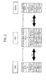
Fig. 2] Fig. 2 is a diagram showing the protocol stack of the mobile communication system according to the first embodiment of the present invention. - [
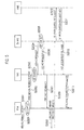
Fig. 3] Fig. 3 is a sequence diagram illustrating the operation of the mobile communication system according to the first embodiment of the present invention. - [
Fig. 4] Fig. 4 is a diagram showing the protocol stack of the mobile communication system according to a second embodiment of the present invention. - [
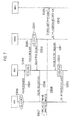
Fig. 5] Fig. 5 is a sequence diagram illustrating the operation of the mobile communication system according to the second embodiment of the present invention. - [
Fig. 6] Fig. 6 is a diagram showing the protocol stack of the mobile communication system according to a third embodiment of the present invention. - [
Fig. 7] Fig. 7 is a sequence diagram illustrating the operation of the mobile communication system according to the third embodiment of the present invention. - [
Fig. 8] Fig. 8 is a diagram showing the protocol stack of a current mobile communication system. - A description will be provided for the mobile communication system according to a first embodiment of the present invention, with reference to
Fig. 1 to Fig. 3 . - The mobile communication system according to the present invention is an LTE-Advanced mobile communication system including, for example, as illustrated in
Fig. 1 , a mobile switching center MME, relay nodes RN1 to RN4, a radio base station DeNB (Donor eNB) 1 that is connected by the relay node RN1, a radio base station DeNB2 that is connected to the relay nodes RN2 and RN3, and a radio base station eNB1. - Herein, the radio base station DeNB1 and the radio base station DeNB2 are connected via an X2-C interface, and the radio base station DeNB2 and the radio base station eNB1 are connected via an X2-C interface.
- Also, the radio base station DeNB1, the radio base station DeNB2, and the radio base station eNB1 are respectively connected with the mobile switching center MME via S1-MME interfaces.
- In such a mobile communication system, the mobile station UE is configured to set a radio bearer between the radio base stations eNB (DeNB) and the relay nodes RN in order to perform radio communication.
- Also, in such a mobile communication system, as illustrated by (6) of
Fig. 1 , the mobile station UE is configured to conduct a handover process between a first state in which a radio bearer is set with the relay node RN4 (the first relay node) in order to communicate via the relay node RN4, the relay node RN3 (the second relay node), and the radio base station DeNB2 (the radio base station), and a second state in which a radio bearer is set with the radio base station DeNB2 in order to communicate via the radio base station DeNB2. - Additionally, in such a handover process, control signals (X2AP signals) involved in the handover process are configured to be sent and received via the radio bearer (Un interface) between the relay node RN4 and the relay node RN3, and via the radio bearer (Un interface) between the relay node RN3 and the radio base station DeNB2.
- Note that in this embodiment, the configuration is such that no radio bearer (Un interface) is set between the relay node RN2 and the radio base station DeNB2.
- Specifically, as illustrated in
Fig. 2 , as X-2C radio bearer functions configured to set the X2-C radio bearer (Un interface) with the relay node RN3, the relay node RN4 includes a physical (PHY) layer function, an MAC (Media Access Control) layer function provided as an upper layer function of the physical (PHY) layer function, an RLC (Radio Link Control) layer function provided as an upper layer function of the MAC layer function, and a PDCP (Packet Data Convergence Protocol) layer function provided as an upper layer function of the RLC layer function. - Note that the relay node RN4 may include an RRC (Radio Resource Control) layer function provided as an upper layer function of the PDCP layer function.
- Moreover, as illustrated in
Fig. 2 , as an upper layer function of the X2-C radio bearer functions, the relay node RN4 may include an IP layer function configured to perform security processes between the relay node RN4 and the relay node RN3, and may include an SCTP layer function configured to perform keep-alive processes for the X2-C radio bearer as an upper layer function of the IP layer function. - Further, the relay node RN4 may include an X2AP layer function configured to send and receive control signals (for example, "HO Request", and "HO Request Ack") involved in the handover process as an upper layer function of the SCTP layer function.
- Similarly, as X2-C radio bearer functions configured to establish an X2-C radio bearer with the relay node RN3 (Un interface), the radio base station DeNB2 includes a physical (PHY) layer function, an MAC layer function provided as an upper layer function of the physical (PHY) layer function, an RLC layer function provided as an upper layer function of the MAC layer function, and a PDCP layer function provided as an upper layer function of the RLC layer function.
- Note that the radio base station DeNB2 may include an RRC layer function provided as an upper layer function of the PDCP layer function.
- As an upper layer function of the X2-C radio bearer functions, the radio base station DeNB2 may also include an IP layer function configured to perform security processes between the relay node RN3 and the radio base station DeNB2, and may include an SCTP layer configured to perform keep-alive processes for the X2-C radio bearer as an upper layer function of the IP layer function.
- The radio base station DeNB2 may also include an X2AP layer function configured to send and receive control signals involved in the handover process, as an upper layer function of the SCTP layer function.
- The relay node RN3 also includes an X2-C radio bearer function configured set an X2-C radio bearer (Un interface) with the relay node RN4 and the radio base station DeNB2.
- The relay node RN3 further includes an IP layer function provided as an upper layer function of the X2-C radio bearer function, with an SCTP function provided as an upper layer function of the IP layer function, and with an X2AP layer function provided as an upper layer function of the SCTP layer function.
- A description is provided below with reference to
Fig. 3 for the operation in the mobile communication system according to this embodiment where the mobile station UE is configured to conduct a handover from a first state in which a radio bearer is set with the relay node RN4 in order to communicate via the relay node RN4, the relay node RN3, and the radio base station DeNB2, to a second state in which a radio bearer is set with the radio base station DeNB2 in order to communicate via the radio base station DeNB2. - As illustrated in
Fig. 3 , the relay node RN2, which manages the "UE Context" of the mobile station UE, decides to perform a handover process in which the mobile station UE shifts from the first state to the second state in step S1000, and then, in step S1001, sends an "HO Request (handover request signal)", requesting a handover of the mobile station UE from the relay node RN4 to the radio base station DeNB2, to the relay node RN3 via the X2-C radio bearer. - The relay node RN3, upon receiving the "HO Request" by means of the X2AP layer function, stores the "UE Context" of the mobile station UE in step S1002, and transfers the "HO Request" to the radio base station DeNB2 via the X2-C radio bearer in step S1003.
- The radio base station DeNB2, upon receiving the "HO Request", stores the "UE Context" of the mobile station UE in step S1004, and sends an "HO Request Ack (handover request acknowledgement signal)" to the relay node RN1 via the X2-C radio bearer in step S3005.
- The relay node RN3, upon receiving the "HO Request Ack" by means of the X2AP layer function, transfers the "HO Request Ack" to the relay node RN4 via the X2-C radio bearer in step S1006.
- In step S1007, the relay node RN4 sends an "HO Command (handover instruction signal)" to the mobile station UE by means of the RRC layer function, in order to instruct a handover to the radio base station DeNB2.
- In step S1008, the mobile station UE sends an "HO Complete (handover completion signal)" to the radio base station DeNB2 by means of the RRC layer function.
- In step S1009, the radio base station DeNB2 sends a "Path Swith Request (path switch request signal)" to the mobile switching center MME via the S1-MME interface.
- In step S1010, the mobile switching center MME sends a "Path Swith Request Ack (path switch request acknowledgement signal)" to the radio base station DeNB2 via the S1-MME interface, and also switches the transfer destination for signals addressed to the mobile station UE from the relay node RN4 to the radio base station DeNB2.
- In step S1011, the radio base station DeNB2 sends a "UE Context Release" to the relay node RN3 via the X2-C radio bearer, and then in step S1012, the relay node RN3 transfers the "UE Context release" to the relay node RN4 via the X2-C radio bearer by means of the X2AP layer function, such that the relay node RN4 terminates management of the "UE Context" of the mobile station UE in reaction to the "UE Context Release".
- Note that in
Fig. 3 , the relay node RN4 and the radio base station DeNB2 may be interchangeable. - As described above, the X2AP layer function in the relay node RN3 is configured to convert the control signals (X2AP signals) involved in the handover process between the relay note RN4 and the relay node RN3, and the control signals (X2AP signals) involved in the handover process between the relay note RN3 and the radio base station DeNB2.
- Further, the X2AP layer function in the relay node RN3 is configured to manage the mobile station ID that is used between the relay note RN4 and the relay node RN3 in association with the mobile station ID that is used between the relay note RN3 and the radio base station DeNB2.
- According to the mobile communication system of this embodiment, it is possible to implement a handover process involving the relay nodes RN without performing a major renovation of the protocol stack of each device used in the LTE mobile communication system.
- A description will be provided for the mobile communication system according to a second embodiment of the present invention, with reference to
Fig. 4 andFig. 5 . The mobile communication system according to the second embodiment of the present invention will be described below by focusing on the differences from the mobile communication system according to the first embodiment described above. - Specifically, as illustrated in
Fig. 4 , the relay node RN4 includes various functions as X-2C radio bearer functions configured to set the X2-C radio bearer (Un interface) with the relay node RN3: such as a physical (PHY) layer function, an MAC layer function provided as an upper layer function of the physical (PHY) layer function, an RLC layer function provided as an upper layer function of the MAC layer function, and a PDCP layer function provided as an upper layer function of the RLC layer function. - Note that the relay node RN4 may include an RRC layer function provided as an upper layer function of the PDCP layer function.
- Further, as illustrated in
Fig. 4 , the relay node RN4 is configured to operate as a proxy of the RRC layer function in the mobile station UE, and does not include an IP layer function configured to perform security processes between the relay node RN4 and the relay node RN3 as an upper layer function of the X2-C radio bearer function, nor with an SCTP layer function configured to perform keep-alive processes for the X2-C radio bearer, nor with an X2AP layer function configured to send and receive control signals involved in the handover process. - Further, the protocol stack of the radio base station DeNB2 and the relay node RN3 is the same as the protocol stack of the mobile communication system according to the first embodiment as illustrated in
Fig. 2 . - A description is provided below with reference to
Fig. 5 for the operation in the mobile communication system according to this embodiment where the mobile station UE is configured to conduct a handover from a first state in which a radio bearer is set with the relay node RN4 in order to communicate via the relay node RN4, the relay node RN3, and the radio base station DeNB2, to a second state in which a radio bearer is set with the radio base station DeNB2 in order to communicate via the radio base station DeNB2. - As illustrated in
Fig. 5 , the relay node RN4, upon receiving a "Measurement Report (measurement report)" from the mobile station UE in step S2000, acquires the "UE Context" of the mobile station UE being managed in step S2001, and then in step S2002, transfers the "Measurement Report" including the "UE Context" of the mobile station UE to the relay node RN3 by means of the RRC layer function. - The relay node RN3 then decides to perform a handover process of the mobile station UE from the relay node RN4 to the radio base station DeNB2 based on the received "Measurement Report", stores the "UE Context" of the mobile station UE in step S2003, and then in step S2004, and sends an "HO Request (handover request signal)" to the radio base station DeNB2 via the X2-C radio bearer, in order to request a handover of the mobile station UE from the relay node RN4 to the radio base station DeNB2.
- The radio base station DeNB2, upon receiving the "HO Request", stores the "UE Context" of the mobile station UE in step S2005, and sends an "HO Request Ack (handover request acknowledgement signal)" to the relay node RN2 via the X2-C radio bearer in step S3006.
- The relay node RN3, upon receiving the "HO Request Ack", sends an "HO Command" (handover instruction signal) to the relay node RN4, in order to instruct a handover to the radio base station DeNB2 by means of the RRC layer function in step S2007.
- In step S2008, the relay node RN4 transfers the received "HO Command" to the mobile station UE by means of the RRC layer function.
- In step S2009, the mobile station UE sends an "HO Complete (handover completion signal)" to the radio base station DeNB2 by means of the RRC layer function.
- In step S2010, the radio base station Den2 sends a "Path Swith Request (path switch request signal)" to the mobile switching center MME via the S1-MME interface.
- In step S2011, the mobile switching center MME sends a "Path Swith Request Ack (path switch request acknowledgement signal)" to the radio base station DeNB2 via the S1-MME interface, and also switches the transfer destination for signals addressed to the mobile station UE from the relay node RN4 to the radio base station DeNB2.
- In step S2021, the radio base station DeNB2 sends the "UE Context Release" to the relay node RN3 via the X2-C radio bearer.
- In step S2013, the relay node RN3, transfers an "RRC Connection Release" to the relay node RN4 by means of the RRC layer function, and the relay node RN4 terminates management of the "UE Context" of the mobile station UE in reaction to the "RRC Connection Release".
- A description will be provided for the mobile communication system according to a third embodiment of the present invention, with reference to
Fig. 6 andFig. 7 . The mobile communication system according to the third embodiment of the present invention will be described below by focusing on the differences from the mobile communication system according to the first embodiment described above. - Specifically, as illustrated in
Fig. 6 , the relay node RN3 includes an X2-C radio bearer function configured to set an X2-C radio bearer (Un interface) with the relay node RN4 and the radio base station DeNB2. - Also, the relay node RN3 includes an IP layer function as an upper layer function of the X2-C radio bearer function, but does not include an SCTP function and X2AP layer function as upper layer functions of the IP layer function.
- Further, the protocol stack of the radio base station DeNB2 and the relay node RN4 is the same as the protocol stack of the mobile communication system according to the first embodiment as illustrated in
Fig. 2 . - A description is provided below with reference to
Fig. 7 for the operation in the mobile communication system according to this embodiment where the mobile station UE is configured to conduct a handover from a first state in which a radio bearer is set with the relay node RN4 in order to communicate via the relay node RN4, the relay node RN3, and the radio base station DeNB2, to a second state in which a radio bearer is set with the radio base station DeNB2 in order to communicate via the radio base station DeNB2. - As illustrated in
Fig. 7 , the relay node RN4, which manages the "UE Context" of the mobile station UE, decides to perform a handover process from the first state of the mobile station UE to the second state thereof in step S3000, and then sends an "HO Request (handover request signal)", requesting a handover by the mobile station UE from the relay node RN4 to the radio base station DeNB2 in step S3001, to the relay node RN3 via the X2-C radio bearer. - The relay node RN3, upon receiving the "HO Request" in step S3002 by means of the IP layer function, transfers the "HO Request" to the radio base station DeNB2 via the X2-C radio bearer in step S3003.
- The radio base station DeNB2, upon receiving the "HO Request", stores the "UE Context" of the mobile station UE in step S3004, and sends an "HO Request Ack (handover request acknowledgement signal)" to the relay node RN3 via the X2-C radio bearer in step S3005.
- The relay node RN3, upon receiving the "HO Request Ack" by means of the IP layer function, transfers the "HO Request Ack" to the relay node RN4 via the X2-C radio bearer in step S3006.
- In step S3007, the relay node RN4 sends an "HO Command (handover instruction signal)" to the mobile station UE by means of the RRC layer function, in order to instruct a handover to the radio base station DeNB2.
- In step S3008, the mobile station UE sends an "HO Complete (handover completion signal)" to the radio base station DeNB2 by means of the RRC layer function.
- In step S3009, the radio base station DeNB2 sends a "Path Swith Request (path switch request signal)" to the mobile switching center MME via the S1-MME interface.
- In step S3010, the mobile switching center MME sends a "Path Swith Request Ack (path switch request acknowledgement signal)" to the radio base station DeNB2 via the S1-MME interface, and also switches the transfer destination for signals addressed to the mobile station UE from the relay node RN4 to the radio base station DeNB2.
- In step S3011, the radio base station DeNB2 sends the "UE Context Release" to the relay node RN3 via the X2-C radio bearer.
- The relay node RN3, upon receiving the "UE Context Release" by means of the I layer function in step S3012, transfers the "UE Context Release" to the relay node RN4 via the X2-C radio bearer in step S3013, such that the relay node RN4 terminates management of the "UE Context" of the mobile station UE in reaction to the "UE Context Release".
- Note that operation of the above described the mobile station UE, the relay node RN, the radio base station eNB and the mobile switching center MME may be implemented by means of hardware, a software module executed by a processor, or a combination of both.
- The software module may be provided in any type of storage medium such as an RAM (Random Access Memory), a flash memory, a ROM (Read Only Memory), an EPROM (Erasable Programmable ROM), an EEPROM (Electronically Erasable and Programmable ROM), a register, a hard disk, a removable disk, or a CD-ROM.
- The storage medium is connected to the processor so that the processor can read and write information from and to the storage medium. Also, the storage medium may be integrated into the processor. Also, the storage medium and the processor may be provided in an ASIC. The ASIC may be provided in the mobile station UE, the relay node RN, the radio base station eNB and the mobile switching center MME. Also, the storage medium and the processor may be provided in the mobile station UE, the relay node RN, the radio base station eNB and the mobile switching center MME as a discrete component.
- Hereinabove, the present invention has been described in detail using the above embodiment; however, it is apparent to those skilled in the art that the present invention is not limited to the embodiment described herein. Modifications and variations of the present invention can be made without departing from the spirit and scope of the present invention defined by the description of the scope of claims. Thus, what is described herein is for illustrative purpose, and has no intention whatsoever to limit the present invention.
Claims (3)
- A mobile communication system, wherein
a first relay node and a second relay node are connected via a radio bearer,
the second relay node and a radio base station are connected via a radio bearer,
a mobile station is configured to perform a handover process between a first state, in which a radio bearer is set with the first relay node in order to communicate via the first relay node, the second relay node, and the radio base station, and a second state, in which a radio bearer is set with the radio base station in order to communicate via the radio base station, and
a mobile station is configured such that during the handover process, control signals involved in the handover process are sent and received via the radio bearer between the first relay node and the second relay node and via the radio bearer between the second relay node and the radio base station. - The mobile communication system according to claim 1, wherein
the first relay node, upon receiving a measurement report from the mobile station, is configured to transfer the measurement report to the second relay node via the radio bearer between the first relay node and the second relay node, and
the second relay node, upon deciding based on the measurement report to initiate the handover process in which the mobile station shifts from the first state to the second state, is configured to send a handover request signal giving notification of this intention, as a control signal involved in the handover process, to the radio base station via the radio bearer between the second relay node and the radio base station. - The mobile communication system according to claim 1, wherein
the first relay node, upon deciding to initiate the handover process in which the mobile station shifts from the first state to the second state, is configured to send a handover request signal giving notification of this intention, as a control signal involved in the handover process, to the second relay node via the radio bearer between the first relay node and the second relay node, and
the second relay node is configured to transfer the received handover request signal to the radio base station via the radio bearer between the second relay node and the radio base station.
Applications Claiming Priority (2)
| Application Number | Priority Date | Filing Date | Title |
|---|---|---|---|
| JP2009110011A JP5225191B2 (en) | 2009-04-28 | 2009-04-28 | Mobile communication system |
| PCT/JP2010/057219 WO2010125975A1 (en) | 2009-04-28 | 2010-04-23 | Mobile communication system |
Publications (2)
| Publication Number | Publication Date |
|---|---|
| EP2426991A1 true EP2426991A1 (en) | 2012-03-07 |
| EP2426991A4 EP2426991A4 (en) | 2013-05-29 |
Family
ID=43032127
Family Applications (1)
| Application Number | Title | Priority Date | Filing Date |
|---|---|---|---|
| EP10769674.2A Withdrawn EP2426991A4 (en) | 2009-04-28 | 2010-04-23 | MOBILE COMMUNICATION SYSTEM |
Country Status (7)
| Country | Link |
|---|---|
| US (1) | US8848663B2 (en) |
| EP (1) | EP2426991A4 (en) |
| JP (1) | JP5225191B2 (en) |
| KR (1) | KR101266033B1 (en) |
| CN (1) | CN102415140A (en) |
| MX (1) | MX2011011385A (en) |
| WO (1) | WO2010125975A1 (en) |
Families Citing this family (12)
| Publication number | Priority date | Publication date | Assignee | Title |
|---|---|---|---|---|
| US20120093066A1 (en) * | 2009-04-27 | 2012-04-19 | Ntt Docomo, Inc. | Mobile communication system |
| CN101938798A (en) * | 2009-07-03 | 2011-01-05 | 中兴通讯股份有限公司 | Method and system for managing terminal mobility in wireless relay system |
| WO2012134116A2 (en) * | 2011-03-25 | 2012-10-04 | Lg Electronics Inc. | Method and apparatus for performing handover procedure in wireless communication system including mobile relay node |
| JP5742532B2 (en) | 2011-07-19 | 2015-07-01 | 富士通株式会社 | Base station, communication method, and wireless communication system |
| ES2647445T3 (en) * | 2012-05-10 | 2017-12-21 | Alcatel Lucent | Message Transfer |
| CN103974228B (en) * | 2013-01-30 | 2019-05-07 | 中兴通讯股份有限公司 | A method and system for realizing X2 proxy |
| JP6563602B2 (en) * | 2015-12-02 | 2019-08-21 | エルジー エレクトロニクス インコーポレイティド | Method and apparatus for supporting mobility of master terminal and companion device thereof in wireless communication system |
| CN108024295B (en) * | 2016-11-03 | 2022-04-19 | 中兴通讯股份有限公司 | Relay transfer method and device, terminal and base station |
| WO2018173460A1 (en) * | 2017-03-23 | 2018-09-27 | 日本電気株式会社 | Base station, wireless relay station, communication method, and non-temporary computer-readable medium which stores program therein |
| JPWO2018173461A1 (en) * | 2017-03-23 | 2020-01-09 | 日本電気株式会社 | Non-transitory computer-readable medium storing base station, wireless relay station, communication method, and program |
| CN111818594A (en) * | 2019-07-31 | 2020-10-23 | 维沃移动通信有限公司 | A network switching method, network device and terminal |
| JP7514122B2 (en) * | 2020-06-26 | 2024-07-10 | Kddi株式会社 | Relay device, communication device, control method, and program for executing handover processing of relay device |
Family Cites Families (18)
| Publication number | Priority date | Publication date | Assignee | Title |
|---|---|---|---|---|
| CA2626895C (en) * | 2005-11-11 | 2013-11-05 | Lg Electronics Inc. | Method of controlling relay communication |
| EP1989906B1 (en) * | 2006-02-28 | 2017-03-22 | Nokia Technologies Oy | Handover in communication networks |
| US8140077B2 (en) | 2006-04-19 | 2012-03-20 | Nokia Corporation | Handover or location update for optimization for relay stations in a wireless network |
| KR100847014B1 (en) * | 2006-11-27 | 2008-07-17 | 한국전자통신연구원 | Handover Method and System in Mobile Communication Network |
| CN101262269B (en) * | 2007-03-05 | 2012-08-29 | 华为技术有限公司 | A cluster node switching method, and communication system |
| GB2447885B (en) * | 2007-03-05 | 2011-03-30 | Toshiba Res Europ Ltd | Fast relay station handover |
| FI20075697A0 (en) * | 2007-10-02 | 2007-10-02 | Nokia Siemens Networks Oy | Method, computer program, apparatus and system |
| EP2207277A4 (en) * | 2007-10-16 | 2015-08-12 | Fujitsu Ltd | RELAY STATION DEVICE, TERMINAL STATION DEVICE, WIRELESS COMMUNICATION SYSTEM, AND CHARGE DISTRIBUTION METHOD |
| ES2436742T3 (en) * | 2008-04-04 | 2014-01-07 | Nokia Solutions And Networks Oy | Moments of action for transfer of mobile stations |
| EP2432280B1 (en) | 2008-05-15 | 2016-06-15 | Telefonaktiebolaget LM Ericsson (publ) | Data forwarding during handover in a self-backhauled cell |
| US8855138B2 (en) * | 2008-08-25 | 2014-10-07 | Qualcomm Incorporated | Relay architecture framework |
| US8340235B2 (en) * | 2008-09-25 | 2012-12-25 | Research In Motion Limited | X-MIMO systems with multi-transmitters and multi-receivers |
| WO2010054903A1 (en) * | 2008-11-17 | 2010-05-20 | Nokia Siemens Networks Oy | Networking capability determination mechanism |
| US8228871B2 (en) * | 2009-03-19 | 2012-07-24 | Telefonaktiebolaget Lm Ericsson (Publ) | Wireless handover optimization |
| EP2417798A1 (en) * | 2009-04-09 | 2012-02-15 | Nokia Siemens Networks Oy | Base station caching for an efficient handover in a mobile telecommunication network with relays |
| US8532056B2 (en) * | 2009-04-13 | 2013-09-10 | Qualcomm Incorporated | Device mobility for split-cell relay networks |
| KR101294517B1 (en) * | 2009-04-21 | 2013-08-07 | 엘지전자 주식회사 | Method of utilizing a relay node in wireless communication system |
| WO2010121661A1 (en) * | 2009-04-24 | 2010-10-28 | Nokia Siemens Networks Oy | Method, apparatus, and related computer program product for load balancing in a relay network |
-
2009
- 2009-04-28 JP JP2009110011A patent/JP5225191B2/en not_active Expired - Fee Related
-
2010
- 2010-04-23 EP EP10769674.2A patent/EP2426991A4/en not_active Withdrawn
- 2010-04-23 CN CN2010800185332A patent/CN102415140A/en active Pending
- 2010-04-23 MX MX2011011385A patent/MX2011011385A/en active IP Right Grant
- 2010-04-23 WO PCT/JP2010/057219 patent/WO2010125975A1/en not_active Ceased
- 2010-04-23 KR KR1020117025553A patent/KR101266033B1/en not_active Expired - Fee Related
- 2010-04-23 US US13/266,608 patent/US8848663B2/en not_active Expired - Fee Related
Also Published As
| Publication number | Publication date |
|---|---|
| KR20120004485A (en) | 2012-01-12 |
| US8848663B2 (en) | 2014-09-30 |
| EP2426991A4 (en) | 2013-05-29 |
| KR101266033B1 (en) | 2013-05-22 |
| US20120099516A1 (en) | 2012-04-26 |
| JP2010259020A (en) | 2010-11-11 |
| CN102415140A (en) | 2012-04-11 |
| JP5225191B2 (en) | 2013-07-03 |
| MX2011011385A (en) | 2011-11-18 |
| WO2010125975A1 (en) | 2010-11-04 |
Similar Documents
| Publication | Publication Date | Title |
|---|---|---|
| CA2760028C (en) | Mobile communication system | |
| EP2426991A1 (en) | Mobile communication system | |
| EP2426994A1 (en) | Mobile communication system | |
| AU2010242666B2 (en) | Mobile communication system | |
| CA2759905C (en) | Mobile communication system | |
| EP2427031A1 (en) | Mobile communication system | |
| AU2013200788B2 (en) | Mobile communication system | |
| JP5058380B2 (en) | Mobile communication system | |
| JP5564092B2 (en) | Mobile communication system |
Legal Events
| Date | Code | Title | Description |
|---|---|---|---|
| PUAI | Public reference made under article 153(3) epc to a published international application that has entered the european phase |
Free format text: ORIGINAL CODE: 0009012 |
|
| 17P | Request for examination filed |
Effective date: 20111123 |
|
| AK | Designated contracting states |
Kind code of ref document: A1 Designated state(s): AT BE BG CH CY CZ DE DK EE ES FI FR GB GR HR HU IE IS IT LI LT LU LV MC MK MT NL NO PL PT RO SE SI SK SM TR |
|
| DAX | Request for extension of the european patent (deleted) | ||
| A4 | Supplementary search report drawn up and despatched |
Effective date: 20130503 |
|
| RIC1 | Information provided on ipc code assigned before grant |
Ipc: H04B 7/26 20060101ALN20130425BHEP Ipc: H04W 16/26 20090101ALI20130425BHEP Ipc: H04W 36/06 20090101AFI20130425BHEP Ipc: H04W 92/04 20090101ALI20130425BHEP Ipc: H04W 84/04 20090101ALN20130425BHEP |
|
| STAA | Information on the status of an ep patent application or granted ep patent |
Free format text: STATUS: THE APPLICATION HAS BEEN WITHDRAWN |
|
| 18W | Application withdrawn |
Effective date: 20140214 |