EP2426754A1 - Reverse use battery pack design - Google Patents
Reverse use battery pack design Download PDFInfo
- Publication number
- EP2426754A1 EP2426754A1 EP10015139A EP10015139A EP2426754A1 EP 2426754 A1 EP2426754 A1 EP 2426754A1 EP 10015139 A EP10015139 A EP 10015139A EP 10015139 A EP10015139 A EP 10015139A EP 2426754 A1 EP2426754 A1 EP 2426754A1
- Authority
- EP
- European Patent Office
- Prior art keywords
- coupling section
- arm
- battery pack
- battery
- contour
- Prior art date
- Legal status (The legal status is an assumption and is not a legal conclusion. Google has not performed a legal analysis and makes no representation as to the accuracy of the status listed.)
- Granted
Links
Images


Classifications
-
- H—ELECTRICITY
- H01—ELECTRIC ELEMENTS
- H01M—PROCESSES OR MEANS, e.g. BATTERIES, FOR THE DIRECT CONVERSION OF CHEMICAL ENERGY INTO ELECTRICAL ENERGY
- H01M50/00—Constructional details or processes of manufacture of the non-active parts of electrochemical cells other than fuel cells, e.g. hybrid cells
- H01M50/20—Mountings; Secondary casings or frames; Racks, modules or packs; Suspension devices; Shock absorbers; Transport or carrying devices; Holders
- H01M50/204—Racks, modules or packs for multiple batteries or multiple cells
- H01M50/207—Racks, modules or packs for multiple batteries or multiple cells characterised by their shape
- H01M50/209—Racks, modules or packs for multiple batteries or multiple cells characterised by their shape adapted for prismatic or rectangular cells
-
- Y—GENERAL TAGGING OF NEW TECHNOLOGICAL DEVELOPMENTS; GENERAL TAGGING OF CROSS-SECTIONAL TECHNOLOGIES SPANNING OVER SEVERAL SECTIONS OF THE IPC; TECHNICAL SUBJECTS COVERED BY FORMER USPC CROSS-REFERENCE ART COLLECTIONS [XRACs] AND DIGESTS
- Y02—TECHNOLOGIES OR APPLICATIONS FOR MITIGATION OR ADAPTATION AGAINST CLIMATE CHANGE
- Y02E—REDUCTION OF GREENHOUSE GAS [GHG] EMISSIONS, RELATED TO ENERGY GENERATION, TRANSMISSION OR DISTRIBUTION
- Y02E60/00—Enabling technologies; Technologies with a potential or indirect contribution to GHG emissions mitigation
- Y02E60/10—Energy storage using batteries
Definitions
- the present invention relates to a battery pack according to the pre-characterizing clauses of claim 1.
- the present invention aims at providing a battery pack that can be used in two distinct battery slots of devices.
- the claimed battery pack includes two different coupling sections disposed at opposite sides of the battery pack so as to couple with corresponding coupling sections of a first battery slot in a specific direction, and with corresponding coupling sections of a second battery slot in a reverse direction.
- FIG. 1 is a schematic diagram of a battery pack 10 and a battery slot 20 of a handheld device according to a first embodiment of the present invention.
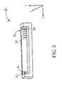
- FIG. 2 is a partial diagram in another view of the battery slot 20 of the battery pack 10 according to the first embodiment.
- the handheld device can be, but not limited to, a foldable type, a clamshell type, a bar type, a slide type, a tablet type, or other types of cell phone, smart phone, personal digital assistant, navigator device, notebook computer, tablet computer, mobile processing device, mobile communications device, and so on.
- the drawings of the subject application only show the partial diagrams related to the battery slot 20 and the battery pack 10 of the handheld device, and the other parts of the handheld device will be omitted herein.
- the battery pack 10 is installed in the battery slot 20 of the handheld device in a detachable and replaceable manner for providing power for the handheld device.
- the battery pack 10 can be, but not limited to, a chargeable battery such as a Ni-MH, a Li-ion battery, and so on.
- the battery pack 10 is installed in the battery slot 20 along a direction of z-axis as shown in FIG. 1 .
- the battery pack 10 has a side surface 11, where a plurality of electrical contacts 12 are disposed, along an installing direction of the battery pack 10, and a plurality of pogo pins 23 are disposed on the battery slot 20 at a corresponding position.
- the electrical contacts 12 couple to the pogo pins 23 respectively so as to be electrically connected and provide power.
- the battery pack 10 varies depending on different handheld devices some engaging structure between the battery pack 10 and the battery slot 20 allows the battery pack 10 to be installed in the handheld device only in a specific manner. Furthermore, the engaging structure also prevents the battery pack 10 from dropping out along a direction of y-axis when the battery pack 10 is installed in the battery slot 20.
- the battery slot 20 includes a first coupling section 21 and a second coupling section 22 located respectively on both sides of a surface that is contacted by the side surface 11 of the battery pack 10.
- the battery pack 10 includes a corresponding third coupling section 13 and a corresponding fourth coupling section 14, located on the side surface 11 of the battery pack 10 respectively.
- the first coupling section 21 includes a protrusion 21 having a first contour (a rectangular contour, but not limited to, is illustrated in the first embodiment, the contour can also be polygon-shaped or arc-shaped), and the corresponding third coupling section 13 of the battery pack 10 includes a first arm 1 31, a second arm 132, and a recess 133.
- the recess 1 33 has a third contour corresponding to the first contour, and the first arm 131, the recess 133, and the second arm 132 are arranged in sequence along the direction of y-axis.
- the recess 133 is formed between the first arm 1 31 and the second arm 132. Due to the third contour of the third coupling section 13, when the battery pack 10 is installed in the battery slot 20 along the direction of z-axis, the protrusion 211 of the first coupling section 21 reaches into the recess 133 such that the first coupling section 21 engages with the third coupling section 13.
- the first arm 131 and the second arm 132 of the third coupling section 13 abut against both sides of the protrusion 211 of the first coupling section 21 along the direction of y-axis so as to restrain the movement of the battery pack 10 along the direction of y-axis with regard to the battery slot 20. In other words, the battery pack 10 will not drop out of the battery slot 20 along the direction of y-axis.
- the second coupling section 22 includes a protrusion 221, which has a second contour (a T-shaped contour, but not limited to, is illustrated in the first embodiment, the contour can also be polygon-shaped or arc-shaped), and the corresponding fourth coupling section 14 of the battery pack 10 includes a first arm 141, a second arm 142, and a recess 143.
- the recess 143 has a fourth contour corresponding to the second contour, and the first arm 141 , the recess 143, and the second arm 142 are arranged in sequence along the direction of y-axis. In other words, the recess 143 is formed between the first arm 141 and the second arm 142.
- the protrusion 221 of the second coupling section 22 reaches into the recess 143 such that the second coupling section 22 engages with the fourth coupling section 14. Meanwhile, the first arm 141 and the second arm 142 of the fourth coupling section 14 abut against both sides of the protrusion 221 of the second coupling section 22 along the direction of y-axis so as to restrain the movement of the battery pack 10 along the direction of y-axis with regard to the battery slot 20. In other words, the battery pack 10 will not drop out of the battery slot 20 along the direction of y-axis.
- At least one coupling section of the coupling section 13, 14 of the battery pack 10 can engage with the corresponding coupling section of the battery slot 20 only, and it cannot engage with the other coupling section of the battery slot 20. Accordingly, when the battery pack 10 is assembled without obeying the aforesaid corresponding manner, the assembly will fail whereby it can avoid mis-plugging of the battery pack 10.
- the first contour of the first coupling section 21 (as well as the corresponding third contour of the third coupling section 13) and the second contour of the second coupling section 22 (as well as the corresponding fourth contour of the fourth coupling section 14) are different in shapes, such that the third contour of the third coupling section 13, for example, the rectangular-shaped contour of the recess 133 in this embodiment, is different from the second contour of the second coupling section 22, for example, the T-shaped contour of the protrusion 221 in this embodiment.
- the protrusion 221 is not allowed to reach into the recess 133 and the battery pack 10 will not be installed therein properly.
- the aforesaid recess 133 and recess 143 are two recesses arranged oppositely at the sides of the battery pack 10 and having asymmetric contours.
- the battery pack 10 of the present invention of the first embodiment can be installed in the battery slot 20' in a reverse manner by rotating along the direction of z-axis, wherein the coupling sections of the battery pack 10 also correspond to the coupling sections of the battery slots 20', too.
- the reversed battery pack 10 can be securely installed in the battery slot 20' and will not drop out along the direction of y-axis in the battery slot 20'.
- the battery pack 10 described in the first embodiment of the present invention effectively solves the problem that a conventional battery pack can only be applied for one handheld device.
- the battery pack 10 can be installed in a second handheld device after rotation. Not only the types of the battery packs and cost for manufacturing the battery packs can be reduced but also the development of new devices is enhanced.
- the third coupling section 13 (as well as the corresponding first coupling section 21 of the battery slot 20) and the fourth coupling section 14 (as well as the corresponding second coupling section 22 of the battery slot 20) preferably have symmetric structures with regard to a central axis L 1 L 2 located on the side surface 11 of the battery pack 10.
- the direction of the central axis L 1 L 2 is the same direction as the x-axis, and the x-axis, the aforesaid y-axis and z-axis are perpendicular to one another.
- FIG. 4 is a schematic diagram of a battery pack 30 and a battery slot 40 of a handheld device according to a second embodiment of the present invention.
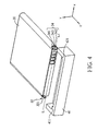
- FIG. 5 is a partial diagram in another view of the battery slot 40 of the battery pack 30 according to the second embodiment.
- a third coupling section 33 of the battery pack 30 includes a protrusion 331.
- a fourth coupling section 34 similar to the fourth coupling section 14 in the first embodiment, includes a first arm 341, a recess 343, and a second arm 342 arranged along a direction of y-axis.
- a first coupling section 41 of the battery slot 40 includes a third arm 411, a recess 413, and a fourth arm 412 arranged along the direction of y-axis.
- a second coupling section 42 includes a protrusion 421 utilized for engaging with the recess 343 of the fourth coupling section 34. Since the third coupling section 33 and the fourth coupling section 34 of the battery pack 30 respectively engage with the first coupling section 41 and the second coupling section 42 of the battery slot 40 in the second embodiment, the battery pack 30 can be installed in the battery slot 40 and will not drop off. Furthermore, the third coupling section 33 and the fourth coupling section 34 are not allowed to engage with the second coupling section 42 and the first coupling section 41 of the battery slot 40 respectively after rotation.
- the battery pack 30 can prevent the possibility that the battery pack 30 is falsely installed in the battery slot 40.
- Installation and engaging relation between the battery pack 30 and the battery slot 40 in the second embodiment are similar to those mentioned in the first embodiment.
- the battery pack 30 can be reversely used to be installed in a battery slot of a second handheld device after rotation. Accordingly, it can enhance convenience of the battery pack 30 in practical application.
- another battery slot with the pogo pins being located at the right portion such as a battery slot 40' of another handheld device as shown in FIG.
- the battery pack 30 in the second embodiment can be installed in the battery slot 40' in a reverse manner after rotating along the direction of z-axis, wherein the coupling sections of the battery pack 30 also correspond to the coupling sections of the battery slots 40', too.
- the reversed battery pack 30 can be securely installed in the battery slot 40' and will not drop out along the direction of y-axis in the battery slot 40'.
- FIG. 7 is a schematic diagram of a battery pack 50 and a battery slot 60 of a handheld device according to a third embodiment of the present invention.
- FIG. 8 is a partial diagram in another view of the battery slot 60 of the battery pack 50 according to the third embodiment.
- a third coupling section 53 of the battery pack 50 includes a protrusion 531 and a fourth coupling section 54 includes a protrusion 541.
- a first coupling section 61 of the battery slot 60 includes a third arm 611, a recess 613, and a fourth arm 612 arranged along a direction of y-axis.
- a second coupling section 62 includes a third arm 621, a recess 623, and a fourth arm 622 arranged along the direction of y-axis.
- the first coupling section 61 of the battery slot 60 engages with the third coupling section 53 of the battery pack 50, and the second coupling section 62 engages with the fourth coupling section 54. Accordingly, the battery pack 50 can be installed in the battery slot 60 and will not drop off. Additionally, due to the difference of contours between the third coupling section 53 and the fourth coupling section 54, the battery pack 50 cannot engage with the second coupling section 62 and the first coupling section 61 of the battery slot 60 after rotation. Accordingly, it can prevent the possibility that the battery pack 50 is falsely installed in the battery slot 60.
- the battery pack 50 can be reversely used to be installed in the battery slot of second handheld device after rotation. Accordingly, it can enhance convenience of the battery pack 50 in practical application.
- the battery pack 50 in the third embodiment can be installed in the battery slot 60' in a reverse manner after rotating along the direction of z-axis, wherein the coupling sections of the battery pack 50 also correspond to the coupling sections of the battery slots 60', too.
- the reversed battery pack 50 can be securely installed in the battery slot 60' and will not drop out along the direction of y-axis in the battery slot 60'.
- the battery pack of the subject application has two coupling sections configured at the side surface in the face of the battery slot of the handheld device, where the coupling sections correspond to coupling structure of the battery slot. As the battery pack is installed in the battery slot, the coupling sections engage with the coupling structure respectively for keeping the battery pack from detaching out of the battery slot.
- the battery pack may also have an upturned position to be installed in a second type of battery slot of another handheld device, where the coupling sections also correspond to and engage with coupling structure of the second battery slot and keep the battery pack from detaching out of the second battery slot.
Landscapes
- Chemical & Material Sciences (AREA)
- Chemical Kinetics & Catalysis (AREA)
- Electrochemistry (AREA)
- General Chemical & Material Sciences (AREA)
- Battery Mounting, Suspending (AREA)
Abstract
Description
- The present invention relates to a battery pack according to the pre-characterizing clauses of claim 1.
- Conventional handheld devices are commonly equipped with replaceable rechargeable batteries. Since each handheld device has a unique battery slot design for its battery, the battery slot of one handheld device needs to be matched with the battery in its shape and corresponding structures. In other words, a conventional battery pack can only be applied for one corresponding battery slot of a handheld device, which accordingly, causes immense increase of cost of design and manufacturing of the batteries.
- This is mind, the present invention aims at providing a battery pack that can be used in two distinct battery slots of devices.
- This is achieved by a battery pack according to claim 1. The dependent claims pertain to corresponding further developments and improvements.
- As will be seen more clearly from the detailed description following below, the claimed battery pack includes two different coupling sections disposed at opposite sides of the battery pack so as to couple with corresponding coupling sections of a first battery slot in a specific direction, and with corresponding coupling sections of a second battery slot in a reverse direction.
- In the following, the invention is further illustrated by way of example, taking reference to the accompanying drawings. Thereof
-
FIG. 1 is a schematic diagram of a battery pack and a battery slot of a handheld device according to a first embodiment of the present invention, -
FIG. 2 andFIG. 3 are partial diagrams in another view of the battery slot of the battery pack according to the first embodiment, -
FIG. 4 is a schematic diagram of a battery pack and a battery slot of a handheld device according to a second embodiment of the present invention, -
FIG. 5 andFIG. 6 are partial diagrams in another view of the battery slot of the battery pack according to the second embodiment, -
FIG. 7 is a schematic diagram of a battery pack and a battery slot of a handheld device according to a third embodiment of the present invention, and -
FIG. 8 andFIG. 9 are partial diagrams in another view of the battery slot of the battery pack according to the third embodiment. - Please refer to
FIG. 1 andFIG. 2 .FIG. 1 is a schematic diagram of abattery pack 10 and abattery slot 20 of a handheld device according to a first embodiment of the present invention.FIG. 2 is a partial diagram in another view of thebattery slot 20 of thebattery pack 10 according to the first embodiment. The handheld device can be, but not limited to, a foldable type, a clamshell type, a bar type, a slide type, a tablet type, or other types of cell phone, smart phone, personal digital assistant, navigator device, notebook computer, tablet computer, mobile processing device, mobile communications device, and so on. For simplicity, the drawings of the subject application only show the partial diagrams related to thebattery slot 20 and thebattery pack 10 of the handheld device, and the other parts of the handheld device will be omitted herein. - The
battery pack 10 is installed in thebattery slot 20 of the handheld device in a detachable and replaceable manner for providing power for the handheld device. Thebattery pack 10 can be, but not limited to, a chargeable battery such as a Ni-MH, a Li-ion battery, and so on. Thebattery pack 10 is installed in thebattery slot 20 along a direction of z-axis as shown inFIG. 1 . Thebattery pack 10 has aside surface 11, where a plurality ofelectrical contacts 12 are disposed, along an installing direction of thebattery pack 10, and a plurality ofpogo pins 23 are disposed on thebattery slot 20 at a corresponding position. When thebattery pack 10 is installed in thebattery slot 20 along the direction of z-axis, theelectrical contacts 12 couple to thepogo pins 23 respectively so as to be electrically connected and provide power. - Since the
battery pack 10 varies depending on different handheld devices some engaging structure between thebattery pack 10 and thebattery slot 20 allows thebattery pack 10 to be installed in the handheld device only in a specific manner. Furthermore, the engaging structure also prevents thebattery pack 10 from dropping out along a direction of y-axis when thebattery pack 10 is installed in thebattery slot 20. - Please refer to
FIG. 2 . Thebattery slot 20 includes afirst coupling section 21 and asecond coupling section 22 located respectively on both sides of a surface that is contacted by theside surface 11 of thebattery pack 10. Thebattery pack 10 includes a correspondingthird coupling section 13 and a corresponding fourth coupling section 14, located on theside surface 11 of thebattery pack 10 respectively. In the first embodiment, thefirst coupling section 21 includes aprotrusion 21 having a first contour (a rectangular contour, but not limited to, is illustrated in the first embodiment, the contour can also be polygon-shaped or arc-shaped), and the correspondingthird coupling section 13 of thebattery pack 10 includes a first arm 1 31, asecond arm 132, and arecess 133. The recess 1 33 has a third contour corresponding to the first contour, and thefirst arm 131, therecess 133, and thesecond arm 132 are arranged in sequence along the direction of y-axis. In other words, therecess 133 is formed between the first arm 1 31 and thesecond arm 132. Due to the third contour of thethird coupling section 13, when thebattery pack 10 is installed in thebattery slot 20 along the direction of z-axis, theprotrusion 211 of thefirst coupling section 21 reaches into therecess 133 such that thefirst coupling section 21 engages with thethird coupling section 13. Meanwhile, thefirst arm 131 and thesecond arm 132 of thethird coupling section 13 abut against both sides of theprotrusion 211 of thefirst coupling section 21 along the direction of y-axis so as to restrain the movement of thebattery pack 10 along the direction of y-axis with regard to thebattery slot 20. In other words, thebattery pack 10 will not drop out of thebattery slot 20 along the direction of y-axis. - Similarly, in the first embodiment, the
second coupling section 22 includes aprotrusion 221, which has a second contour (a T-shaped contour, but not limited to, is illustrated in the first embodiment, the contour can also be polygon-shaped or arc-shaped), and the corresponding fourth coupling section 14 of thebattery pack 10 includes afirst arm 141, asecond arm 142, and arecess 143. Therecess 143 has a fourth contour corresponding to the second contour, and thefirst arm 141 , therecess 143, and thesecond arm 142 are arranged in sequence along the direction of y-axis. In other words, therecess 143 is formed between thefirst arm 141 and thesecond arm 142. Due to the fourth contour of the fourth coupling section 14, when thebattery pack 10 is installed in thebattery slot 20 along the direction of z-axis, theprotrusion 221 of thesecond coupling section 22 reaches into therecess 143 such that thesecond coupling section 22 engages with the fourth coupling section 14. Meanwhile, thefirst arm 141 and thesecond arm 142 of the fourth coupling section 14 abut against both sides of theprotrusion 221 of thesecond coupling section 22 along the direction of y-axis so as to restrain the movement of thebattery pack 10 along the direction of y-axis with regard to thebattery slot 20. In other words, thebattery pack 10 will not drop out of thebattery slot 20 along the direction of y-axis. - In the aforesaid embodiment, in order to avoid that the
battery pack 10 is falsely installed in thebattery slot 20 with reverse side (that is thebattery pack 10 is rotated relative to the z-axis) such that theelectrical contacts 12 of thebattery pack 10 cannot correctly couple to thepogo pins 23 of thebattery slot 20, in this embodiment of the present invention, at least one coupling section of thecoupling section 13, 14 of thebattery pack 10 can engage with the corresponding coupling section of thebattery slot 20 only, and it cannot engage with the other coupling section of thebattery slot 20. Accordingly, when thebattery pack 10 is assembled without obeying the aforesaid corresponding manner, the assembly will fail whereby it can avoid mis-plugging of thebattery pack 10. To achieve such purpose, the first contour of the first coupling section 21 (as well as the corresponding third contour of the third coupling section 13) and the second contour of the second coupling section 22 (as well as the corresponding fourth contour of the fourth coupling section 14) are different in shapes, such that the third contour of thethird coupling section 13, for example, the rectangular-shaped contour of therecess 133 in this embodiment, is different from the second contour of thesecond coupling section 22, for example, the T-shaped contour of theprotrusion 221 in this embodiment. By doing so, if thebattery pack 10 is to be installed with reverse side, with thethird coupling section 13 aiming at thesecond coupling section 22 and the fourth coupling section 14 aiming at thefirst coupling section 21, theprotrusion 221 is not allowed to reach into therecess 133 and thebattery pack 10 will not be installed therein properly. It should be also noticed that theaforesaid recess 133 andrecess 143 are two recesses arranged oppositely at the sides of thebattery pack 10 and having asymmetric contours. - Since the
electrical contacts 12 of thebattery pack 10 are located at the right portion of theside surface 11 in the first embodiment as shown inFIG. 1 , a handheld device having thebattery slot 20 as shown inFIG. 2 , whosepogo pins 23 are located at the left portion, is ready for thebattery pack 10 to be installed in a manner as shown inFIG. 1 . For another battery slot with the pogo pins being located at the right portion, such as the battery slot 20' of another handheld device as shown inFIG. 3 , thebattery pack 10 of the present invention of the first embodiment can be installed in the battery slot 20' in a reverse manner by rotating along the direction of z-axis, wherein the coupling sections of thebattery pack 10 also correspond to the coupling sections of the battery slots 20', too. The reversedbattery pack 10 can be securely installed in the battery slot 20' and will not drop out along the direction of y-axis in the battery slot 20'. Thebattery pack 10 described in the first embodiment of the present invention effectively solves the problem that a conventional battery pack can only be applied for one handheld device. Thebattery pack 10 can be installed in a second handheld device after rotation. Not only the types of the battery packs and cost for manufacturing the battery packs can be reduced but also the development of new devices is enhanced. - Additionally, in the first embodiment, the third coupling section 13 (as well as the corresponding
first coupling section 21 of the battery slot 20) and the fourth coupling section 14 (as well as the correspondingsecond coupling section 22 of the battery slot 20) preferably have symmetric structures with regard to a central axis L1L2 located on theside surface 11 of thebattery pack 10. In this embodiment, the direction of the central axis L1L2 is the same direction as the x-axis, and the x-axis, the aforesaid y-axis and z-axis are perpendicular to one another. - Please refer to
FIG. 4 andFIG. 5 .FIG. 4 is a schematic diagram of abattery pack 30 and abattery slot 40 of a handheld device according to a second embodiment of the present invention.FIG. 5 is a partial diagram in another view of thebattery slot 40 of thebattery pack 30 according to the second embodiment. In the second embodiment of the present invention, athird coupling section 33 of thebattery pack 30 includes aprotrusion 331. Afourth coupling section 34, similar to the fourth coupling section 14 in the first embodiment, includes afirst arm 341, arecess 343, and asecond arm 342 arranged along a direction of y-axis. Afirst coupling section 41 of thebattery slot 40 includes athird arm 411, arecess 413, and afourth arm 412 arranged along the direction of y-axis. Asecond coupling section 42 includes aprotrusion 421 utilized for engaging with therecess 343 of thefourth coupling section 34. Since thethird coupling section 33 and thefourth coupling section 34 of thebattery pack 30 respectively engage with thefirst coupling section 41 and thesecond coupling section 42 of thebattery slot 40 in the second embodiment, thebattery pack 30 can be installed in thebattery slot 40 and will not drop off. Furthermore, thethird coupling section 33 and thefourth coupling section 34 are not allowed to engage with thesecond coupling section 42 and thefirst coupling section 41 of thebattery slot 40 respectively after rotation. Accordingly, it can prevent the possibility that thebattery pack 30 is falsely installed in thebattery slot 40. Installation and engaging relation between thebattery pack 30 and thebattery slot 40 in the second embodiment are similar to those mentioned in the first embodiment. Additionally, thebattery pack 30 can be reversely used to be installed in a battery slot of a second handheld device after rotation. Accordingly, it can enhance convenience of thebattery pack 30 in practical application. For another battery slot with the pogo pins being located at the right portion, such as a battery slot 40' of another handheld device as shown inFIG. 6 , thebattery pack 30 in the second embodiment can be installed in the battery slot 40' in a reverse manner after rotating along the direction of z-axis, wherein the coupling sections of thebattery pack 30 also correspond to the coupling sections of the battery slots 40', too. The reversedbattery pack 30 can be securely installed in the battery slot 40' and will not drop out along the direction of y-axis in the battery slot 40'. - Please refer to
FIG. 7 andFIG. 8 .FIG. 7 is a schematic diagram of abattery pack 50 and abattery slot 60 of a handheld device according to a third embodiment of the present invention.FIG. 8 is a partial diagram in another view of thebattery slot 60 of thebattery pack 50 according to the third embodiment. In the third embodiment of the present invention, athird coupling section 53 of thebattery pack 50 includes aprotrusion 531 and afourth coupling section 54 includes aprotrusion 541. Afirst coupling section 61 of thebattery slot 60 includes athird arm 611, arecess 613, and afourth arm 612 arranged along a direction of y-axis. Asecond coupling section 62 includes athird arm 621, arecess 623, and afourth arm 622 arranged along the direction of y-axis. Thefirst coupling section 61 of thebattery slot 60 engages with thethird coupling section 53 of thebattery pack 50, and thesecond coupling section 62 engages with thefourth coupling section 54. Accordingly, thebattery pack 50 can be installed in thebattery slot 60 and will not drop off. Additionally, due to the difference of contours between thethird coupling section 53 and thefourth coupling section 54, thebattery pack 50 cannot engage with thesecond coupling section 62 and thefirst coupling section 61 of thebattery slot 60 after rotation. Accordingly, it can prevent the possibility that thebattery pack 50 is falsely installed in thebattery slot 60. Installation and engaging relation between thebattery pack 50 and thebattery slot 60 in the third embodiment are similar to those mentioned in the first and second embodiment. Additionally, thebattery pack 50 can be reversely used to be installed in the battery slot of second handheld device after rotation. Accordingly, it can enhance convenience of thebattery pack 50 in practical application. For another battery slot with the pogo pins being located at the right portion, such as a battery slot 60' of another handheld device as shown inFIG. 9 , thebattery pack 50 in the third embodiment can be installed in the battery slot 60' in a reverse manner after rotating along the direction of z-axis, wherein the coupling sections of thebattery pack 50 also correspond to the coupling sections of the battery slots 60', too. The reversedbattery pack 50 can be securely installed in the battery slot 60' and will not drop out along the direction of y-axis in the battery slot 60'. - The battery pack of the subject application has two coupling sections configured at the side surface in the face of the battery slot of the handheld device, where the coupling sections correspond to coupling structure of the battery slot. As the battery pack is installed in the battery slot, the coupling sections engage with the coupling structure respectively for keeping the battery pack from detaching out of the battery slot. The battery pack may also have an upturned position to be installed in a second type of battery slot of another handheld device, where the coupling sections also correspond to and engage with coupling structure of the second battery slot and keep the battery pack from detaching out of the second battery slot.
- All combinations and sub-combinations of the above-described features also belong to the invention.
Claims (8)
- A battery pack (10, 30, 50), for being installed in a first battery slot (20, 40, 60) of a first handheld device or for being rotated along a first direction to be installed in a second battery slot (20', 40', 60') of a second handheld device and for providing power for the first handheld device or the second handheld device, the first battery slot (20, 40, 60) having a first coupling section (21, 41, 61) and a second coupling section (22, 42, 62), the second battery slot (20', 40', 60') having a fifth coupling section (22, 42, 62) and a sixth coupling section (21, 41, 61), the first coupling section (21, 41, 61) and the sixth coupling section (21, 41, 61) having a first contour respectively, the second coupling section (22, 42, 62) and the fifth coupling section (22, 42, 62) having a second contour respectively, the battery pack (10, 30, 50) comprising:a side surface (11); andcharacterised by:a third coupling section (13, 33, 53) disposed on the side surface (11) and having a third contour corresponding to the first contour and engaging with the first coupling section (21,41,61) or the sixth coupling section (21, 41 , 61) along the first direction so as to restrain movement of the battery pack (1 0, 30, 50) along a second direction in the first battery slot (20, 40, 60) or in the second battery slot (20', 40', 60'); anda fourth coupling section (14, 34, 54) disposed on the side surface (11) and having a fourth contour corresponding to the second contour and engaging with the second coupling section (22, 42, 62) or the fifth coupling section (22, 42, 62) along the first direction so as to restrain movement of the battery pack (10, 30, 50) along the second direction in the first battery slot (20, 40, 60) or in the second battery slot (20', 40', 60');wherein the third contour is different from the second contour such that the third coupling section (13, 33, 53) is blocked by the second coupling section (22, 42, 62) along the first direction and can not engage with the second coupling section (22, 42, 62), and the first battery slot (20, 40, 60) has a mirror mapping contour corresponding to the second battery slot (20', 40', 60') with regard to the first direction.
- The battery pack (10) of claim 1, characterised in that each of the first coupling section (21) and the sixth coupling section (21) comprises a protrusion (211) having the first contour, the third coupling section (13) comprises a first arm (131), a recess (1 33), and a second arm (132), the recess (133) which is formed between the first arm (131) and the second arm (132) has the third contour, the first arm (131), the recess (133), and the second arm (132) are arranged along the second direction, and the protrusion (211) reaches into the recess (133) and the first arm (131) and the second arm (132) abut against both sides of the protrusion (21 1) when the third coupling section (13) engages with the first coupling section (21) or the sixth coupling section (21).
- The battery pack (30, 50) of claim 1, characterised in that the third coupling section (33, 53) comprises a protrusion (331, 531) having the third contour, each of the first coupling section (41, 61) and the sixth coupling section (41, 61) comprises a third arm (411, 611), a recess (41 3, 613), and a fourth arm (412, 612), the recess (413, 613) which is formed between the third arm (411, 611) and the fourth arm (412, 612) has the first contour, the third arm (411, 611), the recess (413, 613), and the fourth arm (412, 612) are arranged along the second direction, and the protrusion (331, 531) reaches into the recess (413, 613) along the first direction and is clamped by the third arm (411, 611) and the fourth arm (412, 612) when the third coupling section (33, 53) engages with the first coupling section (41, 61) or the sixth coupling section (41, 61).
- The battery pack (10, 30) of claim 1, characterised in that each of the second coupling section (22, 42) and the fifth coupling section (22, 42) comprises a protrusion (221, 421) having the second contour, the fourth coupling section (14, 34) comprises a first arm (141, 341), a recess (143, 343), and a second arm (142, 342), the recess (143, 343) which is formed between the first arm (141, 341) and the second arm (142, 342) has the fourth contour, the first arm (141, 341), the recess (143, 343), and the second arm (142, 342) are arranged along the second direction, and the protrusion (221, 421) reaches into the recess (143, 343) and the first arm (141 , 341) and the second arm (142, 342) abut against both sides of the protrusion (221, 421) when the fourth coupling section (14, 34) engages with the second coupling section (22, 42) or the fifth coupling section (22, 42).
- The battery pack (50) of claim 1, characterised in that the fourth coupling section (54) comprises a protrusion (541) having the fourth contour, each of the second coupling section (62) and the fifth coupling section (62) comprises a third arm (621), a recess (623), and a fourth arm (622), the recess (623) which is formed between the third arm (621) and the fourth arm (622) has the second contour, the third arm (621), the recess (623), and the fourth arm (622) are arranged along the second direction, and the protrusion (541) reaches into the recess (623) along the first direction and is clamped by the third arm (621) and the fourth arm (622) when the fourth coupling section (54) engages with the second coupling section (62) or the fifth coupling section (62).
- The battery pack (10, 30, 50) of claim 1, characterised in that each of the third coupling section (13, 33, 53) and the fourth coupling section (14, 34, 54) comprises a symmetric structure relative to a central axis located on the side surface (11) and perpendicular to the second direction.
- The battery pack (10, 30, 50) of claim 1, characterised by at least one electrical contact (12) disposed on the side surface (11), each of the first battery slot (20, 40, 60) and the second battery slot (20', 40', 60') having at least one pogo pin (23), the electrical contact (12) electrically connected to the pogo pin (23) of the first battery slot (20, 40, 60) or that of the second battery slot (20', 40', 60') to provide the first handheld device or the second handheld device with a power supply when the battery pack (10, 30, 50) is installed in the first battery slot (20, 40, 60) or the second battery slot (20', 40', 60').
- The battery pack (10, 30, 50) of claim 1, characterised in that the first direction and the second direction are perpendicular to each other.
Applications Claiming Priority (1)
| Application Number | Priority Date | Filing Date | Title |
|---|---|---|---|
| TW099126279A TWI379463B (en) | 2010-08-06 | 2010-08-06 | Reverse use battery pack design |
Publications (2)
| Publication Number | Publication Date |
|---|---|
| EP2426754A1 true EP2426754A1 (en) | 2012-03-07 |
| EP2426754B1 EP2426754B1 (en) | 2013-01-23 |
Family
ID=43495975
Family Applications (1)
| Application Number | Title | Priority Date | Filing Date |
|---|---|---|---|
| EP10015139A Not-in-force EP2426754B1 (en) | 2010-08-06 | 2010-11-30 | Reverse use battery pack design |
Country Status (3)
| Country | Link |
|---|---|
| US (1) | US20120034506A1 (en) |
| EP (1) | EP2426754B1 (en) |
| TW (1) | TWI379463B (en) |
Families Citing this family (2)
| Publication number | Priority date | Publication date | Assignee | Title |
|---|---|---|---|---|
| USD687777S1 (en) * | 2012-05-24 | 2013-08-13 | Sony Corporation | Rechargeable battery |
| CN209045702U (en) * | 2018-11-14 | 2019-06-28 | 东莞新能源科技有限公司 | A kind of battery core and packaging device |
Citations (2)
| Publication number | Priority date | Publication date | Assignee | Title |
|---|---|---|---|---|
| EP1921693A2 (en) * | 2006-11-02 | 2008-05-14 | Sony Corporation | Battery |
| US20090130493A1 (en) * | 2007-11-16 | 2009-05-21 | Microsoft Corporation | Protecting against incorrect battery polarity |
Family Cites Families (5)
| Publication number | Priority date | Publication date | Assignee | Title |
|---|---|---|---|---|
| US5626979A (en) * | 1994-04-08 | 1997-05-06 | Sony Corporation | Battery device and electronic equipment employing the battery device as power source |
| JP4123516B2 (en) * | 2003-12-26 | 2008-07-23 | ソニー株式会社 | Battery device |
| US7117906B2 (en) * | 2004-02-06 | 2006-10-10 | Societe Bic | Datum based interchangeable fuel cell cartridges |
| DE102007044501A1 (en) * | 2007-09-18 | 2009-03-19 | Robert Bosch Gmbh | Battery pack and electrical appliance |
| KR100922468B1 (en) * | 2007-09-21 | 2009-10-21 | 삼성에스디아이 주식회사 | Battery pack |
-
2010
- 2010-08-06 TW TW099126279A patent/TWI379463B/en not_active IP Right Cessation
- 2010-11-24 US US12/954,607 patent/US20120034506A1/en not_active Abandoned
- 2010-11-30 EP EP10015139A patent/EP2426754B1/en not_active Not-in-force
Patent Citations (2)
| Publication number | Priority date | Publication date | Assignee | Title |
|---|---|---|---|---|
| EP1921693A2 (en) * | 2006-11-02 | 2008-05-14 | Sony Corporation | Battery |
| US20090130493A1 (en) * | 2007-11-16 | 2009-05-21 | Microsoft Corporation | Protecting against incorrect battery polarity |
Also Published As
| Publication number | Publication date |
|---|---|
| EP2426754B1 (en) | 2013-01-23 |
| TWI379463B (en) | 2012-12-11 |
| TW201208203A (en) | 2012-02-16 |
| US20120034506A1 (en) | 2012-02-09 |
Similar Documents
| Publication | Publication Date | Title |
|---|---|---|
| EP3978196A1 (en) | Battery pack and electric device | |
| KR101945545B1 (en) | Flexible size and orientation battery system | |
| JP4945340B2 (en) | Battery pack charger and battery pack set | |
| US20070285050A1 (en) | Charger unit for an electronic device including a system for protective storage of an adapter plug | |
| CN111133321B (en) | Shunt resistor and apparatus for detecting current including the same | |
| JP7272430B2 (en) | Battery packs and electrical equipment | |
| EP2426754B1 (en) | Reverse use battery pack design | |
| EP2393142A1 (en) | Battery storage tray | |
| CN101777721B (en) | Electronic device | |
| CN203674764U (en) | Charger | |
| CN105374962A (en) | Mobile electronic equipment without outage in changing battery | |
| US12107302B2 (en) | Overcharge protection device with uneven terminal pads | |
| KR101397859B1 (en) | Assembly structure of battery for portable terminal | |
| US8376568B2 (en) | Rechargeable flashlight electrically charged by a cigar jack | |
| US10181690B1 (en) | Mobile device adapter | |
| CN110571893A (en) | Chargers, Wearables and Charging Systems | |
| JP2008112654A (en) | Secondary battery device and portable electronic device | |
| JP2003331806A (en) | Battery pack | |
| CN216959383U (en) | Portable power source with fixed accomodating of data line | |
| CN102376913B (en) | Reversible battery unit | |
| CN117784947B (en) | Folding keyboard | |
| EP4297162A2 (en) | Battery pack | |
| JP5092351B2 (en) | Mobile terminal device | |
| KR101680423B1 (en) | Jig device for battery cell | |
| EP1852955B1 (en) | Charger unit for an electronic device including a protective storage of an adapter plug |
Legal Events
| Date | Code | Title | Description |
|---|---|---|---|
| 17P | Request for examination filed |
Effective date: 20101130 |
|
| AK | Designated contracting states |
Kind code of ref document: A1 Designated state(s): AL AT BE BG CH CY CZ DE DK EE ES FI FR GB GR HR HU IE IS IT LI LT LU LV MC MK MT NL NO PL PT RO RS SE SI SK SM TR |
|
| AX | Request for extension of the european patent |
Extension state: BA ME |
|
| PUAI | Public reference made under article 153(3) epc to a published international application that has entered the european phase |
Free format text: ORIGINAL CODE: 0009012 |
|
| GRAP | Despatch of communication of intention to grant a patent |
Free format text: ORIGINAL CODE: EPIDOSNIGR1 |
|
| GRAS | Grant fee paid |
Free format text: ORIGINAL CODE: EPIDOSNIGR3 |
|
| GRAA | (expected) grant |
Free format text: ORIGINAL CODE: 0009210 |
|
| AK | Designated contracting states |
Kind code of ref document: B1 Designated state(s): AL AT BE BG CH CY CZ DE DK EE ES FI FR GB GR HR HU IE IS IT LI LT LU LV MC MK MT NL NO PL PT RO RS SE SI SK SM TR |
|
| REG | Reference to a national code |
Ref country code: GB Ref legal event code: FG4D |
|
| REG | Reference to a national code |
Ref country code: CH Ref legal event code: EP |
|
| REG | Reference to a national code |
Ref country code: AT Ref legal event code: REF Ref document number: 595380 Country of ref document: AT Kind code of ref document: T Effective date: 20130215 Ref country code: CH Ref legal event code: EP |
|
| REG | Reference to a national code |
Ref country code: IE Ref legal event code: FG4D |
|
| REG | Reference to a national code |
Ref country code: DE Ref legal event code: R096 Ref document number: 602010004760 Country of ref document: DE Effective date: 20130321 |
|
| REG | Reference to a national code |
Ref country code: AT Ref legal event code: MK05 Ref document number: 595380 Country of ref document: AT Kind code of ref document: T Effective date: 20130123 |
|
| REG | Reference to a national code |
Ref country code: LT Ref legal event code: MG4D |
|
| REG | Reference to a national code |
Ref country code: NL Ref legal event code: VDEP Effective date: 20130123 |
|
| PG25 | Lapsed in a contracting state [announced via postgrant information from national office to epo] |
Ref country code: AT Free format text: LAPSE BECAUSE OF FAILURE TO SUBMIT A TRANSLATION OF THE DESCRIPTION OR TO PAY THE FEE WITHIN THE PRESCRIBED TIME-LIMIT Effective date: 20130123 Ref country code: IS Free format text: LAPSE BECAUSE OF FAILURE TO SUBMIT A TRANSLATION OF THE DESCRIPTION OR TO PAY THE FEE WITHIN THE PRESCRIBED TIME-LIMIT Effective date: 20130523 Ref country code: ES Free format text: LAPSE BECAUSE OF FAILURE TO SUBMIT A TRANSLATION OF THE DESCRIPTION OR TO PAY THE FEE WITHIN THE PRESCRIBED TIME-LIMIT Effective date: 20130504 Ref country code: LT Free format text: LAPSE BECAUSE OF FAILURE TO SUBMIT A TRANSLATION OF THE DESCRIPTION OR TO PAY THE FEE WITHIN THE PRESCRIBED TIME-LIMIT Effective date: 20130123 Ref country code: BE Free format text: LAPSE BECAUSE OF FAILURE TO SUBMIT A TRANSLATION OF THE DESCRIPTION OR TO PAY THE FEE WITHIN THE PRESCRIBED TIME-LIMIT Effective date: 20130123 Ref country code: SE Free format text: LAPSE BECAUSE OF FAILURE TO SUBMIT A TRANSLATION OF THE DESCRIPTION OR TO PAY THE FEE WITHIN THE PRESCRIBED TIME-LIMIT Effective date: 20130123 Ref country code: NO Free format text: LAPSE BECAUSE OF FAILURE TO SUBMIT A TRANSLATION OF THE DESCRIPTION OR TO PAY THE FEE WITHIN THE PRESCRIBED TIME-LIMIT Effective date: 20130423 Ref country code: BG Free format text: LAPSE BECAUSE OF FAILURE TO SUBMIT A TRANSLATION OF THE DESCRIPTION OR TO PAY THE FEE WITHIN THE PRESCRIBED TIME-LIMIT Effective date: 20130423 |
|
| PG25 | Lapsed in a contracting state [announced via postgrant information from national office to epo] |
Ref country code: PL Free format text: LAPSE BECAUSE OF FAILURE TO SUBMIT A TRANSLATION OF THE DESCRIPTION OR TO PAY THE FEE WITHIN THE PRESCRIBED TIME-LIMIT Effective date: 20130123 Ref country code: SI Free format text: LAPSE BECAUSE OF FAILURE TO SUBMIT A TRANSLATION OF THE DESCRIPTION OR TO PAY THE FEE WITHIN THE PRESCRIBED TIME-LIMIT Effective date: 20130123 Ref country code: NL Free format text: LAPSE BECAUSE OF FAILURE TO SUBMIT A TRANSLATION OF THE DESCRIPTION OR TO PAY THE FEE WITHIN THE PRESCRIBED TIME-LIMIT Effective date: 20130123 Ref country code: FI Free format text: LAPSE BECAUSE OF FAILURE TO SUBMIT A TRANSLATION OF THE DESCRIPTION OR TO PAY THE FEE WITHIN THE PRESCRIBED TIME-LIMIT Effective date: 20130123 Ref country code: PT Free format text: LAPSE BECAUSE OF FAILURE TO SUBMIT A TRANSLATION OF THE DESCRIPTION OR TO PAY THE FEE WITHIN THE PRESCRIBED TIME-LIMIT Effective date: 20130523 Ref country code: GR Free format text: LAPSE BECAUSE OF FAILURE TO SUBMIT A TRANSLATION OF THE DESCRIPTION OR TO PAY THE FEE WITHIN THE PRESCRIBED TIME-LIMIT Effective date: 20130424 Ref country code: LV Free format text: LAPSE BECAUSE OF FAILURE TO SUBMIT A TRANSLATION OF THE DESCRIPTION OR TO PAY THE FEE WITHIN THE PRESCRIBED TIME-LIMIT Effective date: 20130123 |
|
| PG25 | Lapsed in a contracting state [announced via postgrant information from national office to epo] |
Ref country code: HR Free format text: LAPSE BECAUSE OF FAILURE TO SUBMIT A TRANSLATION OF THE DESCRIPTION OR TO PAY THE FEE WITHIN THE PRESCRIBED TIME-LIMIT Effective date: 20130123 Ref country code: RS Free format text: LAPSE BECAUSE OF FAILURE TO SUBMIT A TRANSLATION OF THE DESCRIPTION OR TO PAY THE FEE WITHIN THE PRESCRIBED TIME-LIMIT Effective date: 20130123 |
|
| PG25 | Lapsed in a contracting state [announced via postgrant information from national office to epo] |
Ref country code: EE Free format text: LAPSE BECAUSE OF FAILURE TO SUBMIT A TRANSLATION OF THE DESCRIPTION OR TO PAY THE FEE WITHIN THE PRESCRIBED TIME-LIMIT Effective date: 20130123 Ref country code: CZ Free format text: LAPSE BECAUSE OF FAILURE TO SUBMIT A TRANSLATION OF THE DESCRIPTION OR TO PAY THE FEE WITHIN THE PRESCRIBED TIME-LIMIT Effective date: 20130123 Ref country code: SK Free format text: LAPSE BECAUSE OF FAILURE TO SUBMIT A TRANSLATION OF THE DESCRIPTION OR TO PAY THE FEE WITHIN THE PRESCRIBED TIME-LIMIT Effective date: 20130123 Ref country code: RO Free format text: LAPSE BECAUSE OF FAILURE TO SUBMIT A TRANSLATION OF THE DESCRIPTION OR TO PAY THE FEE WITHIN THE PRESCRIBED TIME-LIMIT Effective date: 20130123 Ref country code: DK Free format text: LAPSE BECAUSE OF FAILURE TO SUBMIT A TRANSLATION OF THE DESCRIPTION OR TO PAY THE FEE WITHIN THE PRESCRIBED TIME-LIMIT Effective date: 20130123 |
|
| PG25 | Lapsed in a contracting state [announced via postgrant information from national office to epo] |
Ref country code: CY Free format text: LAPSE BECAUSE OF FAILURE TO SUBMIT A TRANSLATION OF THE DESCRIPTION OR TO PAY THE FEE WITHIN THE PRESCRIBED TIME-LIMIT Effective date: 20130123 |
|
| PLBE | No opposition filed within time limit |
Free format text: ORIGINAL CODE: 0009261 |
|
| STAA | Information on the status of an ep patent application or granted ep patent |
Free format text: STATUS: NO OPPOSITION FILED WITHIN TIME LIMIT |
|
| PG25 | Lapsed in a contracting state [announced via postgrant information from national office to epo] |
Ref country code: IT Free format text: LAPSE BECAUSE OF FAILURE TO SUBMIT A TRANSLATION OF THE DESCRIPTION OR TO PAY THE FEE WITHIN THE PRESCRIBED TIME-LIMIT Effective date: 20130123 |
|
| 26N | No opposition filed |
Effective date: 20131024 |
|
| REG | Reference to a national code |
Ref country code: DE Ref legal event code: R097 Ref document number: 602010004760 Country of ref document: DE Effective date: 20131024 |
|
| PG25 | Lapsed in a contracting state [announced via postgrant information from national office to epo] |
Ref country code: MC Free format text: LAPSE BECAUSE OF FAILURE TO SUBMIT A TRANSLATION OF THE DESCRIPTION OR TO PAY THE FEE WITHIN THE PRESCRIBED TIME-LIMIT Effective date: 20130123 |
|
| REG | Reference to a national code |
Ref country code: IE Ref legal event code: MM4A |
|
| PG25 | Lapsed in a contracting state [announced via postgrant information from national office to epo] |
Ref country code: IE Free format text: LAPSE BECAUSE OF NON-PAYMENT OF DUE FEES Effective date: 20131130 |
|
| REG | Reference to a national code |
Ref country code: CH Ref legal event code: PCOW Free format text: NEW ADDRESS: NO. 23, XINGHUA ROAD TAOYUAN DISTRICT, TAOYUAN CITY 330 (TW) |
|
| PG25 | Lapsed in a contracting state [announced via postgrant information from national office to epo] |
Ref country code: SM Free format text: LAPSE BECAUSE OF FAILURE TO SUBMIT A TRANSLATION OF THE DESCRIPTION OR TO PAY THE FEE WITHIN THE PRESCRIBED TIME-LIMIT Effective date: 20130123 |
|
| PG25 | Lapsed in a contracting state [announced via postgrant information from national office to epo] |
Ref country code: TR Free format text: LAPSE BECAUSE OF FAILURE TO SUBMIT A TRANSLATION OF THE DESCRIPTION OR TO PAY THE FEE WITHIN THE PRESCRIBED TIME-LIMIT Effective date: 20130123 |
|
| REG | Reference to a national code |
Ref country code: CH Ref legal event code: PL |
|
| PG25 | Lapsed in a contracting state [announced via postgrant information from national office to epo] |
Ref country code: LU Free format text: LAPSE BECAUSE OF NON-PAYMENT OF DUE FEES Effective date: 20131130 Ref country code: HU Free format text: LAPSE BECAUSE OF FAILURE TO SUBMIT A TRANSLATION OF THE DESCRIPTION OR TO PAY THE FEE WITHIN THE PRESCRIBED TIME-LIMIT; INVALID AB INITIO Effective date: 20101130 Ref country code: MK Free format text: LAPSE BECAUSE OF FAILURE TO SUBMIT A TRANSLATION OF THE DESCRIPTION OR TO PAY THE FEE WITHIN THE PRESCRIBED TIME-LIMIT Effective date: 20130123 Ref country code: CH Free format text: LAPSE BECAUSE OF NON-PAYMENT OF DUE FEES Effective date: 20141130 Ref country code: LI Free format text: LAPSE BECAUSE OF NON-PAYMENT OF DUE FEES Effective date: 20141130 |
|
| PG25 | Lapsed in a contracting state [announced via postgrant information from national office to epo] |
Ref country code: MT Free format text: LAPSE BECAUSE OF FAILURE TO SUBMIT A TRANSLATION OF THE DESCRIPTION OR TO PAY THE FEE WITHIN THE PRESCRIBED TIME-LIMIT Effective date: 20130123 |
|
| REG | Reference to a national code |
Ref country code: FR Ref legal event code: PLFP Year of fee payment: 6 |
|
| REG | Reference to a national code |
Ref country code: FR Ref legal event code: PLFP Year of fee payment: 7 |
|
| REG | Reference to a national code |
Ref country code: FR Ref legal event code: PLFP Year of fee payment: 8 |
|
| REG | Reference to a national code |
Ref country code: FR Ref legal event code: PLFP Year of fee payment: 9 |
|
| PG25 | Lapsed in a contracting state [announced via postgrant information from national office to epo] |
Ref country code: AL Free format text: LAPSE BECAUSE OF FAILURE TO SUBMIT A TRANSLATION OF THE DESCRIPTION OR TO PAY THE FEE WITHIN THE PRESCRIBED TIME-LIMIT Effective date: 20130123 |
|
| PGFP | Annual fee paid to national office [announced via postgrant information from national office to epo] |
Ref country code: DE Payment date: 20181120 Year of fee payment: 9 |
|
| PGFP | Annual fee paid to national office [announced via postgrant information from national office to epo] |
Ref country code: FR Payment date: 20181011 Year of fee payment: 9 Ref country code: GB Payment date: 20181128 Year of fee payment: 9 |
|
| REG | Reference to a national code |
Ref country code: DE Ref legal event code: R119 Ref document number: 602010004760 Country of ref document: DE |
|
| GBPC | Gb: european patent ceased through non-payment of renewal fee |
Effective date: 20191130 |
|
| PG25 | Lapsed in a contracting state [announced via postgrant information from national office to epo] |
Ref country code: FR Free format text: LAPSE BECAUSE OF NON-PAYMENT OF DUE FEES Effective date: 20191130 Ref country code: GB Free format text: LAPSE BECAUSE OF NON-PAYMENT OF DUE FEES Effective date: 20191130 Ref country code: DE Free format text: LAPSE BECAUSE OF NON-PAYMENT OF DUE FEES Effective date: 20200603 |