EP2426688A1 - Backlighting assembly for a keypad - Google Patents
Backlighting assembly for a keypad Download PDFInfo
- Publication number
- EP2426688A1 EP2426688A1 EP10175018A EP10175018A EP2426688A1 EP 2426688 A1 EP2426688 A1 EP 2426688A1 EP 10175018 A EP10175018 A EP 10175018A EP 10175018 A EP10175018 A EP 10175018A EP 2426688 A1 EP2426688 A1 EP 2426688A1
- Authority
- EP
- European Patent Office
- Prior art keywords
- light
- light guide
- assembly
- key
- mobile device
- Prior art date
- Legal status (The legal status is an assumption and is not a legal conclusion. Google has not performed a legal analysis and makes no representation as to the accuracy of the status listed.)
- Granted
Links
Images



Classifications
-
- H—ELECTRICITY
- H01—ELECTRIC ELEMENTS
- H01H—ELECTRIC SWITCHES; RELAYS; SELECTORS; EMERGENCY PROTECTIVE DEVICES
- H01H13/00—Switches having rectilinearly-movable operating part or parts adapted for pushing or pulling in one direction only, e.g. push-button switch
- H01H13/70—Switches having rectilinearly-movable operating part or parts adapted for pushing or pulling in one direction only, e.g. push-button switch having a plurality of operating members associated with different sets of contacts, e.g. keyboard
- H01H13/83—Switches having rectilinearly-movable operating part or parts adapted for pushing or pulling in one direction only, e.g. push-button switch having a plurality of operating members associated with different sets of contacts, e.g. keyboard characterised by legends, e.g. Braille, liquid crystal displays, light emitting or optical elements
-
- H—ELECTRICITY
- H01—ELECTRIC ELEMENTS
- H01H—ELECTRIC SWITCHES; RELAYS; SELECTORS; EMERGENCY PROTECTIVE DEVICES
- H01H2219/00—Legends
- H01H2219/036—Light emitting elements
- H01H2219/044—Edge lighting of layer
-
- H—ELECTRICITY
- H01—ELECTRIC ELEMENTS
- H01H—ELECTRIC SWITCHES; RELAYS; SELECTORS; EMERGENCY PROTECTIVE DEVICES
- H01H2219/00—Legends
- H01H2219/054—Optical elements
- H01H2219/06—Reflector
-
- H—ELECTRICITY
- H01—ELECTRIC ELEMENTS
- H01H—ELECTRIC SWITCHES; RELAYS; SELECTORS; EMERGENCY PROTECTIVE DEVICES
- H01H2219/00—Legends
- H01H2219/054—Optical elements
- H01H2219/062—Light conductor
-
- H—ELECTRICITY
- H01—ELECTRIC ELEMENTS
- H01H—ELECTRIC SWITCHES; RELAYS; SELECTORS; EMERGENCY PROTECTIVE DEVICES
- H01H2219/00—Legends
- H01H2219/054—Optical elements
- H01H2219/062—Light conductor
- H01H2219/0622—Light conductor only an illuminated ring around keys
-
- H—ELECTRICITY
- H01—ELECTRIC ELEMENTS
- H01H—ELECTRIC SWITCHES; RELAYS; SELECTORS; EMERGENCY PROTECTIVE DEVICES
- H01H2219/00—Legends
- H01H2219/054—Optical elements
- H01H2219/064—Optical isolation of switch sites
-
- H—ELECTRICITY
- H01—ELECTRIC ELEMENTS
- H01H—ELECTRIC SWITCHES; RELAYS; SELECTORS; EMERGENCY PROTECTIVE DEVICES
- H01H2229/00—Manufacturing
- H01H2229/034—Positioning of layers
Definitions
- the field of this disclosure relates generally to keypads and keypad backlighting assemblies, with particular but by no means exclusive application to keypads of mobile communications devices.
- Light may be emitted from a light source located within the electronic device, and directed toward one or multiple keys, illuminating such key(s).
- a keypad assembly includes at least one key; at least one light emitting source configured to emit light; and a light guide assembly configured to receive the emitted light and direct the light toward the at least one key.
- the light guide assembly may comprise both a light guide film and a light guide frame.
- the keypad assembly may be configured for use in a mobile device.
- a backlighting assembly may be provided for use within a keypad assembly having at least one key.
- the backlighting assembly may comprise: at least one side firing light emitting source configured to emit light; and a light guide assembly configured to receive the emitted light and direct the light toward the at least one key.
- the light guide assembly may comprise both a light guide film, and a light guide frame.
- the keypad assembly may be configured for use in a mobile device.
- the light guide film may be configured to receive the emitted light (or light emitted from the light emitting source) and communicate the received light to the light guide frame.
- the light guide frame may be configured to direct the communicated light toward the at least one key.
- the light guide film may be configured to direct the received light toward the at least one key.
- a method for providing backlighting for a keypad assembly having at least one key may be provided.
- the method may comprise providing a keypad assembly having at least one light emitting source, wherein the light emitting source is configured to emit light; providing a light guide assembly configured to receive the emitted light and to direct the received light toward the at least one key, wherein the light guide assembly comprises a light guide film and a light guide frame; and causing the light emitting source to emit light.
- the light guide film may be configured to receive the emitted light and communicate the received light to the light guide frame.
- the light guide film may be configured to direct the emitted light toward the at least one key.
- a mobile device may be a two-way communication device with advanced data communication capabilities having the capability to communicate with other computer systems.
- a mobile device may also comprise the capability for voice communications.
- it may be referred to as a data messaging device, a two-way pager, a cellular telephone with data messaging capabilities, a wireless Internet appliance, or a data communication device (with or without telephony capabilities), for example.
- a mobile device may communicate with other devices through a network of transceiver stations.
- FIGS. 1 through 3 To aid the reader in understanding the structure of a mobile device and how it communicates with other devices, reference is made to FIGS. 1 through 3 .
- Mobile device 100 comprises a number of components, the controlling component being microprocessor 102.
- Microprocessor 102 controls the overall operation of mobile device 100.
- Communication functions, including data and voice communications, may be performed through communication subsystem 104.
- Communication subsystem 104 may be configured to receive messages from and send messages to a wireless network 200.
- communication subsystem 104 may be configured in accordance with the Global System for Mobile Communication (GSM) and General Packet Radio Services (GPRS) standards.
- GSM Global System for Mobile Communication
- GPRS General Packet Radio Services
- the GSM/GPRS wireless network is used worldwide and it is expected that these standards may be supplemented or superseded eventually by Enhanced Data GSM Environment (EDGE) and Universal Mobile Telecommunications Service (UMTS), and Ultra Mobile Broadband (UMB), etc. New standards are still being defined, but it is believed that they will have similarities to the network behaviour described herein, and it will also be understood by persons skilled in the art that the embodiments of the present disclosure are intended to use any other suitable standards that are developed in the future.
- the wireless link connecting communication subsystem 104 with network 200 represents one or more different Radio Frequency (RF) channels, operating according to defined protocols specified for GSM/GPRS communications. With newer network protocols, these channels are capable of supporting both circuit switched voice communications and packet switched data communications.
- RF Radio Frequency
- wireless network associated with mobile device 100 is a GSM/GPRS wireless network in one example implementation of mobile device 100
- other wireless networks may also be associated with mobile device 100 in variant implementations.
- Different types of wireless networks that may be employed include, for example, data-centric wireless networks, voice-centric wireless networks, and dual-mode networks that can support both voice and data communications over the same physical base stations.
- Combined dual-mode networks include, but are not limited to, Code Division Multiple Access (CDMA) or CDMA2000 networks, GSM/GPRS networks (as mentioned above), and future third-generation (3G) networks like EDGE and UMTS.
- CDMA Code Division Multiple Access
- 3G Third-generation
- Some older examples of data-centric networks include the Mobitex TM Radio Network and the DataTAC TM Radio Network.
- Examples of older voice-centric data networks include Personal Communication Systems (PCS) networks like GSM and Time Division Multiple Access (TDMA) systems.
- PCS Personal Communication Systems
- TDMA Time Division Multiple Access
- Other network communication technologies that may be employed include, for example, Integrated Digital Enhanced Network (iDENTM), Evolution-Data Optimized (EV-DO), and High Speed Packet Access (HSPA), etc.
- iDENTM Integrated Digital Enhanced Network
- EV-DO Evolution-Data Optimized
- HSPA High Speed Packet Access
- Microprocessor 102 may also interact with additional subsystems such as a Random Access Memory (RAM) 106, flash memory 108, display 110, auxiliary input/output (I/O) subsystem 112, serial port 114, keyboard 116, speaker 118, microphone 120, short-range communications subsystem 122 and other device subsystems 124.
- RAM Random Access Memory
- I/O auxiliary input/output subsystem 112
- serial port 114 serial port 114
- keyboard 116 keyboard 116
- speaker 118 microphone 120
- short-range communications subsystem 122 short-range communications subsystem 122
- other device subsystems 124 other device subsystems
- Some of the subsystems of mobile device 100 perform communication-related functions, whereas other subsystems may provide "resident" or on-device functions.
- display 110 and keyboard 116 may be used for both communication-related functions, such as entering a text message for transmission over network 200, as well as device-resident functions such as a calculator or task list.
- Operating system software used by microprocessor 102 is typically stored in a persistent store such as flash memory 108 , which may alternatively be a read-only memory (ROM) or similar storage element (not shown).
- ROM read-only memory
- RAM 106 volatile store
- Mobile device 100 may send and receive communication signals over network 200 after network registration or activation procedures have been completed. Network access may be associated with a subscriber or user of a mobile device 100. To identify a subscriber, mobile device 100 may provide for a Subscriber Identity Module (“SIM”) card 126 to be inserted in a SIM interface 128 in order to communicate with a network. SIM 126 may be one example type of a conventional "smart card" used to identify a subscriber of mobile device 100 and to personalize the mobile device 100, among other things. Without SIM 126, mobile device 100 may not be fully operational for communication with network 200. By inserting SIM 126 into SIM interface 128, a subscriber may access all subscribed services.
- SIM Subscriber Identity Module
- SIM 126 may include a processor and memory for storing information. Once SIM 126 is inserted in SIM interface 128, it may be coupled to microprocessor 102. In order to identify the subscriber, SIM 126 may contain some user parameters such as an International Mobile Subscriber Identity (IMSI). By using SIM 126, a subscriber may not necessarily be bound by any single physical mobile device. SIM 126 may store additional subscriber information for a mobile device as well, including datebook (or calendar) information and recent call information.
- IMSI International Mobile Subscriber Identity
- Mobile device 100 may be a battery-powered device and may comprise a battery interface 132 for receiving one or more rechargeable batteries 130.
- Battery interface 132 may be coupled to a regulator (not shown), which assists battery 130 in providing power V+ to mobile device 100.
- a regulator not shown
- future technologies such as micro fuel cells may provide power to mobile device 100.
- mobile device 100 may be solar-powered.
- Microprocessor 102 in addition to its operating system functions, enables execution of software applications on mobile device 100.
- a set of applications that control basic device operations, including data and voice communication applications, may be installed on mobile device 100 during its manufacture.
- Another application that may be loaded onto mobile device 100 is a personal information manager (PIM).
- PIM has functionality to organize and manage data items of interest to a subscriber, such as, but not limited to, e-mail, calendar events, voice mails, appointments, and task items.
- a PIM application has the ability to send and receive data items via wireless network 200.
- PIM data items may be seamlessly integrated, synchronized, and updated via wireless network 200 with the mobile device subscriber's corresponding data items stored and/or associated with a host computer system. This functionality may create a mirrored host computer on mobile device 100 with respect to such items. This can be particularly advantageous where the host computer system is the mobile device subscriber's office computer system.
- Additional applications may also be loaded onto mobile device 100 through network 200, auxiliary I/O subsystem 112, serial port 114, short-range communications subsystem 122, or any other suitable subsystem 124.
- This flexibility in application installation increases the functionality of mobile device 100 and may provide enhanced on-device functions, communication-related functions, or both.
- secure communication applications may enable electronic commerce functions and other such financial transactions to be performed using mobile device 100.
- Serial port 114 enables a subscriber to set preferences through an external device or software application and extends the capabilities of mobile device 100 by providing for information or software downloads to mobile device 100 other than through a wireless communication network.
- the alternate download path may, for example, be used to load an encryption key onto mobile device 100 through a direct and thus reliable and trusted connection to provide secure device communication.
- Short-range communications subsystem 122 provides for communication between mobile device 100 and different systems or devices, without the use of network 200.
- subsystem 122 may include an infrared device and associated circuits and components for short-range communication.
- Examples of short range communication include standards developed by the Infrared Data Association (IrDA), Bluetooth ® , and the 802.11 family of standards (Wi-Fi ® ) developed by IEEE.
- a received signal such as a text message, an e-mail message, or web page download is processed by communication subsystem 104 and input to microprocessor 102.
- Microprocessor 102 then processes the received signal for output to display 110 or alternatively to auxiliary I/O subsystem 112.
- a subscriber may also compose data items, such as e-mail messages, for example, using keyboard 116 in conjunction with display 110 and possibly auxiliary I/O subsystem 112.
- Auxiliary subsystem 112 may include devices such as: a touch screen, mouse, track ball, optical trackpad, infrared fingerprint detector, or a roller wheel with dynamic button pressing capability.
- Keyboard 116 may comprise an alphanumeric keyboard and/or telephone-type keypad, for example.
- a composed item may be transmitted over network 200 through communication subsystem 104.
- mobile device 100 For voice communications, the overall operation of mobile device 100 may be substantially similar, except that the received signals may be processed and output to speaker 118, and signals for transmission may be generated by microphone 120.
- Alternative voice or audio I/O subsystems such as a voice message recording subsystem, may also be implemented on mobile device 100.
- voice or audio signal output is accomplished primarily through speaker 118, display 110 may also be used to provide additional information such as the identity of a calling party, duration of a voice call, or other voice call related information.
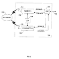
- Communication subsystem 104 may comprise a receiver 150, a transmitter 152, one or more embedded or internal antenna elements 154, 156, Local Oscillators (LOs) 158, and a processing module such as a Digital Signal Processor (DSP) 160.
- LOs Local Oscillators
- DSP Digital Signal Processor
- communication subsystem 104 The particular design of communication subsystem 104 is dependent upon the network 200 in which mobile device 100 is intended to operate; thus, it should be understood that the design illustrated in FIG. 2 serves only as one example.
- Signals received by antenna 154 through network 200 are input to receiver 150, which may perform such common receiver functions as signal amplification, frequency down conversion, filtering, channel selection, and analog-to-digital (A/D) conversion.
- A/D conversion of a received signal allows more complex communication functions such as demodulation and decoding to be performed in DSP 160.
- signals to be transmitted are processed, including modulation and encoding, by DSP 160.
- DSP-processed signals are input to transmitter 152 for digital-to-analog (D/A) conversion, frequency up conversion, filtering, amplification and transmission over network 200 via antenna 156.
- DSP 160 not only processes communication signals, but also provides for receiver and transmitter control. For example, the gains applied to communication signals in receiver 150 and transmitter 152 may be adaptively controlled through automatic gain control algorithms implemented in DSP 160.
- the wireless link between mobile device 100 and a network 200 may contain one or more different channels, typically different RF channels, and associated protocols used between mobile device 100 and network 200.
- a RF channel is generally a limited resource, typically due to limits in overall bandwidth and limited battery power of mobile device 100.
- transmitter 152 When mobile device 100 is fully operational, transmitter 152 may be typically keyed or turned on only when it is sending to network 200 and may otherwise be turned off to conserve resources. Similarly, receiver 150 may be periodically turned off to conserve power until it is needed to receive signals or information (if at all) during designated time periods.
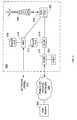
- network 200 comprises one or more nodes 202.
- Mobile device 100 communicates with a node 202 within wireless network 200.
- node 202 is configured in accordance with GPRS and GSM technologies; however, in other embodiments, different standards may be implemented as discussed in more detail above.
- Node 202 includes a base station controller (BSC) 204 with an associated tower station 206, a Packet Control Unit (PCU) 208 added for GPRS support in GSM, a Mobile Switching Center (MSC) 210, a Home Location Register (HLR) 212, a Visitor Location Registry (VLR) 214, a Serving GPRS Support Node (SGSN) 216, a Gateway GPRS Support Node (GGSN) 218, and a Dynamic Host Configuration Protocol (DHCP) server 220.
- BSC base station controller
- PCU Packet Control Unit
- MSC Mobile Switching Center
- HLR Home Location Register
- VLR Visitor Location Registry
- SGSN Serving GPRS Support Node
- GGSN Gateway GPRS Support Node
- DHCP Dynamic Host Configuration Protocol
- MSC 210 is coupled to BSC 204 and to a landline network, such as a Public Switched Telephone Network (PSTN) 222 to satisfy circuit switched requirements.
- PSTN Public Switched Telephone Network
- the connection through PCU 208, SGSN 216 and GGSN 218 to the public or private network (Internet) 224 (also referred to herein generally as a shared network infrastructure) represents the data path for GPRS capable mobile devices.
- BSC 204 also contains a Packet Control Unit (PCU) 208 that connects to SGSN 216 to control segmentation, radio channel allocation and to satisfy packet switched requirements.
- PCU Packet Control Unit
- HLR 212 is shared between MSC 210 and SGSN 216. Access to VLR 214 is controlled by MSC 210.
- Station 206 may be a fixed transceiver station. Station 206 and BSC 204 together may form the fixed transceiver equipment.
- the fixed transceiver equipment provides wireless network coverage for a particular coverage area commonly referred to as a "cell".
- the fixed transceiver equipment transmits communication signals to and receives communication signals from mobile devices within its cell via station 206.
- the fixed transceiver equipment normally performs such functions as modulation and possibly encoding and/or encryption of signals to be transmitted to the mobile device in accordance with particular, usually predetermined, communication protocols and parameters, under control of its controller.
- the fixed transceiver equipment similarly demodulates and possibly decodes and decrypts, if necessary, any communication signals received from mobile device 100 within its cell. Communication protocols and parameters may vary between different nodes. For example, one node may employ a different modulation scheme and operate at different frequencies than other nodes.
- HLR 212 For all mobile devices 100 registered with a specific network, permanent configuration data such as a user profile may be stored in HLR 212.
- HLR 212 may also contain location information for each registered mobile device and can be queried to determine the current location of a mobile device.
- MSC 210 is responsible for a group of location areas and stores the data of the mobile devices currently in its area of responsibility in VLR 214.
- VLR 214 also contains information on mobile devices that are visiting other networks. The information in VLR 214 includes part of the permanent mobile device data transmitted from HLR 212 to VLR 214 for faster access. By moving additional information from a remote HLR 212 node to VLR 214, the amount of traffic between these nodes can be reduced so that voice and data services can be provided with faster response times while requiring less use of computing resources.
- SGSN 216 and GGSN 218 are elements that may be added for GPRS support; namely packet switched data support, within GSM.
- SGSN 216 and MSC 210 have similar responsibilities within wireless network 200 by keeping track of the location of each mobile device 100.
- SGSN 216 also performs security functions and access control for data traffic on network 200.
- GGSN 218 provides internetworking connections with external packet switched networks and connects to one or more SGSNs 216 via an Internet Protocol (IP) backbone network operated within the network 200.
- IP Internet Protocol
- a given mobile device 100 performs a "GPRS Attach" to acquire an IP address and to access data services. This normally is not present in circuit switched voice channels as Integrated Services Digital Network (ISDN) addresses may be generally used for routing incoming and outgoing calls.
- ISDN Integrated Services Digital Network
- GPRS capable networks may use private, dynamically assigned IP addresses, thus requiring a DHCP server 220 connected to the GGSN 218.
- RADIUS Remote Authentication Dial-In User Service
- a logical connection is established from a mobile device 100, through PCU 208, and SGSN 216 to an Access Point Node (APN) within GGSN 218, for example.
- APN represents a logical end of an IP tunnel that can either access direct Internet compatible services or private network connections.
- the APN also represents a security mechanism for network 200, insofar as each mobile device 100 must be assigned to one or more APNs and mobile devices 100 cannot generally exchange data without first performing a GPRS Attach to an APN that it has been authorized to use.
- the APN may be considered to be similar to an Internet domain name such as "myconnection.wireless.com".
- IPsec IP Security
- VPN Virtual Private Networks
- PDP Packet Data Protocol
- network 200 will run an idle timer for each PDP Context to determine if there is a lack of activity.
- the PDP Context can be deallocated and the IP address returned to the IP address pool managed by DHCP server 220.
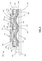
- the keypad assembly 400 may be used within electronic devices, such as within the keyboard 116 of the mobile device 100 described above.
- the keypad assembly 400 includes keys (or keycaps) 410 positioned within a flexible deflection web 420.
- the keys 410 are positioned atop, and operatively coupled to, corresponding actuator portions 425 of the deflection web 420.
- the keys 410 may be adhered to the actuators 425 or, alternatively, the keys 410 and actuators 425 may be provided with complementary male and female features to permit the keys 410 to sit within the actuators 425.
- each key 410 and actuator 425 correspond to, and are aligned with, a dome 430 (which may be made of metal) and a switch sensor 433 coupled to a base 440 of the keypad assembly 400.
- Each key 410 is operatively coupled to its corresponding dome 430.
- the corresponding metal dome 430 collapses and engages the corresponding sensor switch 433. Accordingly, engagement of a sensor switch 433 produces a signal that a corresponding key 410 has been depressed.
- the metal domes 430 and sensor switches 433 operate like dome switches commonly used in the field.
- a dome overlay 436 may be provided within the keypad assembly 400 in order to restrict lateral movement of the domes 430 within the assembly 400.
- the portions 437 of the dome overlay 436 not in contact with a dome 430 may be operatively coupled to the base 440 via coupling elements 450, in order to localize the domes between the portions 437 of the dome overlay 436.
- the coupling elements 450 may comprise, for example, an adhesive or alternatively, a spacer having adhesive tape on either side.
- the spacer may comprise a material with favorable sealing characteristics, in order to prevent dust and/or water from contaminating the dome and switch area within the keypad assembly 400.
- the keypad assembly 400 is also provided with a light emitting source 461 and a light guide assembly 470.
- the light emitting source 461 and light guide assembly 470 are appropriately positioned with respect to one another such that emitted light 462 from the light emitting source (or light source) 461 is received by the light guide assembly 470.
- the light guide assembly 470 is configured to direct light it receives from the light emitting source 461 towards the keys 410 of the keypad assembly 400.
- the light guide assembly 470 will be discussed in greater detail below.
- the light emitting source (or light source) 461 may comprise a commercially available side firing (or side emitting) light emitting diode (LED).
- a side firing LED typically comprises a housing for the LED that is mountable at a base of the housing and an LED configured to emit light from a side wall-adjacent the base-of the housing.
- the housing of a top firing LED which is also mountable at its base, contains an LED configured to emit light from a top surface-opposite the base-of the housing.
- LEDs typically require there to be a certain amount of clearance (or space) between the surface of the LED, from which the light is emitted, and a light guide or other object in order for the LEDs to function efficiently.
- This space is typically referred as the LED leading space gap.
- any required leading space gap is lateral (i.e. generally perpendicular to the key press direction 431) rather than vertical (i.e. generally parallel to the key press direction 431). Consequently, the thickness of the keypad assembly 400 may be reduced by using side firing LEDs instead of top firing LEDs as the light source 461 within a keypad assembly 400.
- FIG. 5 illustrates an enlargement of a selected number of components-namely, the light guide assembly 470, the light source 461, the deflection web 420, and the keys 410 -of the embodiment of the keypad assembly 400 shown in FIG. 4 , in isolation.
- the elements included in FIG. 5 are illustrated having an operative relationship with one another that they would have when installed within the keypad assembly 400.
- the light emitting source 461 and the light guide assembly 470 collectively make up a backlighting assembly 560 as referred to herein.
- the light guide assembly 470 comprises a light guide film 471 and a light guide frame 475.
- An edge 572 of the light guide film 471 is positioned adjacent the light source 461 such that light 462 emitted from the light source 461 is received by the light guide film 471 through its edge 572.
- received light 563 For the purposes of this disclosure, once light emitted from the light source 461 (emitted light 462) enters the light guide film 471, it is referred to as received light 563.
- the light guide film 471 absent any light directing features, is configured to contain a substantial portion of the received light 563 as it travels through the film.
- the light guide film 471 may be provided with several micro features 573a, 573b configured to emit received light 563 out from the light guide film 471.
- the micro features 573a, 573b have been illustrated schematically.
- one or more micro features 573a, 573b may be provided at predetermined locations of the light guide film 471 so as to align with the keys 410 of the keypad assembly 400 when the light guide film 471 is positioned within the assembly 400.
- a dome overlay 436 FIG. 4
- the micro features 573a may be located near the apex of domes formed in the light guide film 471.
- received light 563 traveling through the light guide film 471 intersects with a micro feature 573a, a portion of the light 563 is directed toward the key 410 in alignment with that micro feature 573a.
- received light 563 directed by micro features 573a in line with the key(s) 410
- the primary directed light 565 may serve as the primary source of backlighting for the key(s) 410 of the keypad assembly 400.
- the deflection web 420 may be made from a substantially translucent (or semitransparent) material to ensure that a relatively high portion of the primary directed light 565 is able to pass through the deflection web 420 (including the actuators 425) and reach the key(s) 410.
- One or more micro features 573b may also be provided at predetermined locations of the light guide film 471 so as to align with the light guide frame 475, when the two light guide components (film and frame) are in their installed positions within the keypad assembly 400.
- a portion of the received light 563 is communicated to the light guide frame 475.
- communicated light 564 received light 563 communicated from the light guide film 471 to the light guide frame 475 is referred to as communicated light 564.
- the light guide frame 475 may then direct the communicated light 564 toward the keys 410.
- the micro features 573a, 573b provided in the light guide film 471 may comprise one or more cavities etched into a surface of the film.
- the cavities may, for example, comprise v-shaped cuts, or white printing dots (or micro dots).
- a plurality of micro features 573a, 573b may form a two dimensional array on the light guide film's 471 surface that helps to emit received light 563 from the light guide film 471 evenly.
- these and/or other known micro optical features may be provided to the light guide film 471 to direct light therefrom.
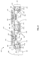
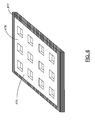
- FIG. 6 shows a perspective view of a light guide frame 475 according to an embodiment of the present disclosure, and is illustrative of the exterior structure of the frame 475.
- the example light guide frame 475 shown is for use with a standard alphanumeric twelve-key keypad assembly (0-9, #, *).
- Those of ordinary skill in the art will appreciate that other configurations of frame 475 may also exist to correspond to keypad assemblies with different numbers of and arrangements of keys, e.g. a full QWERTY keypad assembly.
- the light guide frame 475 may be manufactured as a two-shot injection molded part.
- the first shot 478 may be made of a material with a relatively high transmittance in the visible light spectrum (e.g. a clear resin) in order to afford the frame 475 light transferring capabilities; and, the second shot 477 may be of a substantially reflective material (e.g. a black, or opaque white resin) for preventing light from leaking out.
- a substantially reflective material e.g. a black, or opaque white resin
- the light guide frame 475 may be configured to direct the communicated light 564 (from the light guide film 471) toward one or several keys 410.
- communicated light 564 directed toward the key(s) 410 by the light guide frame 475 is referred to as secondary directed light 566.
- the light guide frame 475 may be provided with one or more directional elements 476. As was the case with the micro features 573a, 573b, directional elements 476 have been illustrated schematically. Those of ordinary skill in the art will appreciate that the directional elements 476 may not be representative of the actual characteristics of such elements, physical or otherwise.
- the directional elements 476 may be provided in the material of the first shot 478.
- the directional features 476 may comprise resin blocks with sloped surfaces which act to redirect some or all of the communicated light 564 toward the key(s) 410.
- the directional elements 476 may be provided in the mold before the first shot 478 is injected.
- the deflection web 420 may comprise a substantially translucent (or semitransparent) material to help ensure that a relatively large portion of the secondary directed light 566 reaches the key(s) 410.
- the light guide frame 475 may be made of one or more substantially rigid materials.
- the light guide frame 475 and the deflection web 420 may be co-molded.
- the light guide frame 475 may provide structural support for the deflection web 420.
- the structural support afforded to the deflection web 420 by the light guide frame 475 may effectively isolate each key 410 and corresponding elements (i.e. dome 430 and in some cases actuator portion 425 of the deflection web 420 ) from the depression of adjacent keys 410.
- a light guide frame 475 with substantial rigidity, co-molded to a deflection web 420 may substantially prevent movement of one portion of the deflection web 420 (corresponding to a key 410 ) from translating to any of the other portions of the deflection web 420 (corresponding to any of the other keys 410).
- This mechanical isolation of each actuator portion 425 of the deflection web 420 may lead to a better tactile feel to a user of the keypad assembly 400.
- the light guide frame 475 may be provided with location pins (not shown), and the light guide film 471 may be provided with location pin holes (not shown).
- the location pins (not shown) of the frame 475 may be slotted through the location pin holes (not shown) of the film 471 when the two light guide components are installed within the keypad assembly 400.
- a light shielding layer 480 may be provided atop the light guide frame 475 in order to help prevent light from escaping the light guide frame 475 in undesired areas.
- the light shielding layer 480 may be made of polyethylene terephthalate colored black with white painting on the surface which faces the light guide frame 475.
- FIG. 7 illustrates an example light shielding layer 480 that may be overlaid onto the light guide frame 475 in the direction of arrows 10.
- the light shielding layer 480 may be attached to the "top" surface of the light guide frame 475 using an adhesive.
- a keypad assembly 400 having at least one key 410 (the method referred to generally as 800 ) will now be discussed.
- a keypad assembly 400 having at least one light emitting source 461, configured to emit light, is provided at Block 810.
- a light guide assembly 470 comprising both a light guide film 471 and a light guide frame 475, is provided for use within the keypad assembly 400.
- the light guide assembly 470 may be configured within the keypad assembly 400 so as to receive light emitted (or emitted light 462 ) from the light source(s) 461 toward the key(s) 410 of the keypad assembly 400.
- a suitable configuration may be achieved by aligning an edge 572 of the light guide film 471 with the light emitted from the light emitting source 461, and appropriately aligning the light guide frame 475 with the light guide film 471.
- the two light guide components 471, 475 may cooperate to direct light 462 emitted from the light source 461 toward the key(s) 410 of the keypad assembly 400 via micro features 573a, 573b and directional elements 476 in the light guide film 471 and light guide frame 475, respectively.
- the at least one light emitting source 461 is caused to emit light.
- the emitted light 462 enters the light guide film 471 as received light 563 which is then directed from the light guide film 471 toward the key(s) 410, or communicated from the light guide film 471 to the light guide frame 475 and subsequently directed toward the key(s) 410 by the light guide frame 475.
- keypad assemblies 400 and backlighting assemblies 560 described herein incorporate light guide assemblies 470 having both a light guide film 471 and a light guide frame 475.
- the thickness of a keypad assembly 400 (and therefore the electronic device incorporating the keypad assembly 400) may be reduced by using a side firing LED and eliminating the need to accommodate the leading space gap typically required of top firing light sources.
- side firing light sources are used in conjunction with light guide films 471, as opposed to light guide frames 475. Supplementing the light guiding capabilities of the light guide film 471 with those of a light guide frame 475 may allow for the use of a thinner light guide film 471, potentially resulting in a thinner keypad assembly 400.
- the use of the light guide frame 475 may provide structural support to a deflection web 420 of a keypad assembly 400, which may effectively isolate the keys 410 from one another, and in turn, result in a greater tactile feel to a user of the keypad assembly 400.
Landscapes
- Input From Keyboards Or The Like (AREA)
Abstract
Description
- The field of this disclosure relates generally to keypads and keypad backlighting assemblies, with particular but by no means exclusive application to keypads of mobile communications devices.
- It is often desirable to provide backlighting to the keys of a keypad assembly used in electronic devices such as mobile communications devices in darkened lighting conditions. Light may be emitted from a light source located within the electronic device, and directed toward one or multiple keys, illuminating such key(s).
- In one broad aspect, there may be provided a keypad assembly. The keypad assembly includes at least one key; at least one light emitting source configured to emit light; and a light guide assembly configured to receive the emitted light and direct the light toward the at least one key. The light guide assembly may comprise both a light guide film and a light guide frame. The keypad assembly may be configured for use in a mobile device.
- In another broad aspect, a backlighting assembly may be provided for use within a keypad assembly having at least one key. The backlighting assembly may comprise: at least one side firing light emitting source configured to emit light; and a light guide assembly configured to receive the emitted light and direct the light toward the at least one key. The light guide assembly may comprise both a light guide film, and a light guide frame. The keypad assembly may be configured for use in a mobile device.
- The light guide film may be configured to receive the emitted light (or light emitted from the light emitting source) and communicate the received light to the light guide frame. In turn, the light guide frame may be configured to direct the communicated light toward the at least one key. Further, the light guide film may be configured to direct the received light toward the at least one key.
- In another broad aspect, a method for providing backlighting for a keypad assembly having at least one key may be provided. The method may comprise providing a keypad assembly having at least one light emitting source, wherein the light emitting source is configured to emit light; providing a light guide assembly configured to receive the emitted light and to direct the received light toward the at least one key, wherein the light guide assembly comprises a light guide film and a light guide frame; and causing the light emitting source to emit light.
- The light guide film may be configured to receive the emitted light and communicate the received light to the light guide frame. The light guide film may be configured to direct the emitted light toward the at least one key.
- Some embodiments of the system and methods described herein make reference to a mobile device. A mobile device may be a two-way communication device with advanced data communication capabilities having the capability to communicate with other computer systems. A mobile device may also comprise the capability for voice communications. Depending on the functionality provided by a mobile device, it may be referred to as a data messaging device, a two-way pager, a cellular telephone with data messaging capabilities, a wireless Internet appliance, or a data communication device (with or without telephony capabilities), for example. A mobile device may communicate with other devices through a network of transceiver stations.
- Embodiments are described in further detail below, by way of example only, with reference to the accompanying drawings, in which:
-
FIG. 1 is a block diagram of a mobile device in one example implementation; -
FIG. 2 is a block diagram of a communication subsystem component of the mobile device ofFIG. 1 ; -
FIG. 3 is a block diagram of a node of a wireless network; -
FIG. 4 is a section view of a portion of a keypad assembly according to an embodiment of the present disclosure; -
FIG. 5 is a section view of selected elements of the keypad assembly ofFIG. 4 ; -
FIG. 6 is a perspective view of an example light guide frame according to the present disclosure; -
FIG. 7 is an exploded perspective view of the light guide frame ofFIG. 6 to which an example light shielding layer is overlaid; and -
FIG. 8 is a logical flow diagram of a method for providing backlighting for a keypad assembly according to the present disclosure. - To aid the reader in understanding the structure of a mobile device and how it communicates with other devices, reference is made to
FIGS. 1 through 3 . - Referring first to
FIG. 1 , a block diagram of a mobile device in one example implementation is shown generally as 100.Mobile device 100 comprises a number of components, the controlling component beingmicroprocessor 102.Microprocessor 102 controls the overall operation ofmobile device 100. Communication functions, including data and voice communications, may be performed throughcommunication subsystem 104.Communication subsystem 104 may be configured to receive messages from and send messages to awireless network 200. In one example implementation ofmobile device 100,communication subsystem 104 may be configured in accordance with the Global System for Mobile Communication (GSM) and General Packet Radio Services (GPRS) standards. The GSM/GPRS wireless network is used worldwide and it is expected that these standards may be supplemented or superseded eventually by Enhanced Data GSM Environment (EDGE) and Universal Mobile Telecommunications Service (UMTS), and Ultra Mobile Broadband (UMB), etc. New standards are still being defined, but it is believed that they will have similarities to the network behaviour described herein, and it will also be understood by persons skilled in the art that the embodiments of the present disclosure are intended to use any other suitable standards that are developed in the future. The wireless link connectingcommunication subsystem 104 withnetwork 200 represents one or more different Radio Frequency (RF) channels, operating according to defined protocols specified for GSM/GPRS communications. With newer network protocols, these channels are capable of supporting both circuit switched voice communications and packet switched data communications. - Although the wireless network associated with
mobile device 100 is a GSM/GPRS wireless network in one example implementation ofmobile device 100, other wireless networks may also be associated withmobile device 100 in variant implementations. Different types of wireless networks that may be employed include, for example, data-centric wireless networks, voice-centric wireless networks, and dual-mode networks that can support both voice and data communications over the same physical base stations. Combined dual-mode networks include, but are not limited to, Code Division Multiple Access (CDMA) or CDMA2000 networks, GSM/GPRS networks (as mentioned above), and future third-generation (3G) networks like EDGE and UMTS. Some older examples of data-centric networks include the Mobitex™ Radio Network and the DataTAC™ Radio Network. Examples of older voice-centric data networks include Personal Communication Systems (PCS) networks like GSM and Time Division Multiple Access (TDMA) systems. Other network communication technologies that may be employed include, for example, Integrated Digital Enhanced Network (iDEN™), Evolution-Data Optimized (EV-DO), and High Speed Packet Access (HSPA), etc. -
Microprocessor 102 may also interact with additional subsystems such as a Random Access Memory (RAM) 106,flash memory 108,display 110, auxiliary input/output (I/O)subsystem 112,serial port 114,keyboard 116,speaker 118,microphone 120, short-range communications subsystem 122 andother device subsystems 124. - Some of the subsystems of
mobile device 100 perform communication-related functions, whereas other subsystems may provide "resident" or on-device functions. By way of example,display 110 andkeyboard 116 may be used for both communication-related functions, such as entering a text message for transmission overnetwork 200, as well as device-resident functions such as a calculator or task list. Operating system software used bymicroprocessor 102 is typically stored in a persistent store such asflash memory 108, which may alternatively be a read-only memory (ROM) or similar storage element (not shown). Those skilled in the art will appreciate that the operating system, specific device applications, or parts thereof, may be temporarily loaded into a volatile store such asRAM 106. -
Mobile device 100 may send and receive communication signals overnetwork 200 after network registration or activation procedures have been completed. Network access may be associated with a subscriber or user of amobile device 100. To identify a subscriber,mobile device 100 may provide for a Subscriber Identity Module ("SIM")card 126 to be inserted in aSIM interface 128 in order to communicate with a network. SIM 126 may be one example type of a conventional "smart card" used to identify a subscriber ofmobile device 100 and to personalize themobile device 100, among other things. Without SIM 126,mobile device 100 may not be fully operational for communication withnetwork 200. By insertingSIM 126 intoSIM interface 128, a subscriber may access all subscribed services. Services may include, without limitation: web browsing and messaging such as e-mail, voice mail, Short Message Service (SMS), and Multimedia Messaging Services (MMS). More advanced services may include, without limitation: point of sale, field service and sales force automation.SIM 126 may include a processor and memory for storing information. OnceSIM 126 is inserted inSIM interface 128, it may be coupled tomicroprocessor 102. In order to identify the subscriber,SIM 126 may contain some user parameters such as an International Mobile Subscriber Identity (IMSI). By usingSIM 126, a subscriber may not necessarily be bound by any single physical mobile device.SIM 126 may store additional subscriber information for a mobile device as well, including datebook (or calendar) information and recent call information. -
Mobile device 100 may be a battery-powered device and may comprise abattery interface 132 for receiving one or morerechargeable batteries 130.Battery interface 132 may be coupled to a regulator (not shown), which assistsbattery 130 in providing power V+ tomobile device 100. Although current technology makes use of a battery, future technologies such as micro fuel cells may provide power tomobile device 100. In some embodiments,mobile device 100 may be solar-powered. -
Microprocessor 102, in addition to its operating system functions, enables execution of software applications onmobile device 100. A set of applications that control basic device operations, including data and voice communication applications, may be installed onmobile device 100 during its manufacture. Another application that may be loaded ontomobile device 100 is a personal information manager (PIM). A PIM has functionality to organize and manage data items of interest to a subscriber, such as, but not limited to, e-mail, calendar events, voice mails, appointments, and task items. A PIM application has the ability to send and receive data items viawireless network 200. PIM data items may be seamlessly integrated, synchronized, and updated viawireless network 200 with the mobile device subscriber's corresponding data items stored and/or associated with a host computer system. This functionality may create a mirrored host computer onmobile device 100 with respect to such items. This can be particularly advantageous where the host computer system is the mobile device subscriber's office computer system. - Additional applications may also be loaded onto
mobile device 100 throughnetwork 200, auxiliary I/O subsystem 112,serial port 114, short-range communications subsystem 122, or any othersuitable subsystem 124. This flexibility in application installation increases the functionality ofmobile device 100 and may provide enhanced on-device functions, communication-related functions, or both. For example, secure communication applications may enable electronic commerce functions and other such financial transactions to be performed usingmobile device 100. -
Serial port 114 enables a subscriber to set preferences through an external device or software application and extends the capabilities ofmobile device 100 by providing for information or software downloads tomobile device 100 other than through a wireless communication network. The alternate download path may, for example, be used to load an encryption key ontomobile device 100 through a direct and thus reliable and trusted connection to provide secure device communication. - Short-
range communications subsystem 122 provides for communication betweenmobile device 100 and different systems or devices, without the use ofnetwork 200. For example,subsystem 122 may include an infrared device and associated circuits and components for short-range communication. Examples of short range communication include standards developed by the Infrared Data Association (IrDA), Bluetooth®, and the 802.11 family of standards (Wi-Fi®) developed by IEEE. - In use, a received signal such as a text message, an e-mail message, or web page download is processed by
communication subsystem 104 and input tomicroprocessor 102.Microprocessor 102 then processes the received signal for output to display 110 or alternatively to auxiliary I/O subsystem 112. A subscriber may also compose data items, such as e-mail messages, for example, usingkeyboard 116 in conjunction withdisplay 110 and possibly auxiliary I/O subsystem 112.Auxiliary subsystem 112 may include devices such as: a touch screen, mouse, track ball, optical trackpad, infrared fingerprint detector, or a roller wheel with dynamic button pressing capability.Keyboard 116 may comprise an alphanumeric keyboard and/or telephone-type keypad, for example. A composed item may be transmitted overnetwork 200 throughcommunication subsystem 104. - For voice communications, the overall operation of
mobile device 100 may be substantially similar, except that the received signals may be processed and output tospeaker 118, and signals for transmission may be generated bymicrophone 120. Alternative voice or audio I/O subsystems, such as a voice message recording subsystem, may also be implemented onmobile device 100. Although voice or audio signal output is accomplished primarily throughspeaker 118,display 110 may also be used to provide additional information such as the identity of a calling party, duration of a voice call, or other voice call related information. - Referring now to
FIG. 2 , a block diagram of thecommunication subsystem component 104 ofFIG. 1 is shown.Communication subsystem 104 may comprise areceiver 150, atransmitter 152, one or more embedded orinternal antenna elements - The particular design of
communication subsystem 104 is dependent upon thenetwork 200 in whichmobile device 100 is intended to operate; thus, it should be understood that the design illustrated inFIG. 2 serves only as one example. Signals received byantenna 154 throughnetwork 200 are input toreceiver 150, which may perform such common receiver functions as signal amplification, frequency down conversion, filtering, channel selection, and analog-to-digital (A/D) conversion. A/D conversion of a received signal allows more complex communication functions such as demodulation and decoding to be performed inDSP 160. In a similar manner, signals to be transmitted are processed, including modulation and encoding, byDSP 160. These DSP-processed signals are input totransmitter 152 for digital-to-analog (D/A) conversion, frequency up conversion, filtering, amplification and transmission overnetwork 200 viaantenna 156.DSP 160 not only processes communication signals, but also provides for receiver and transmitter control. For example, the gains applied to communication signals inreceiver 150 andtransmitter 152 may be adaptively controlled through automatic gain control algorithms implemented inDSP 160. - The wireless link between
mobile device 100 and anetwork 200 may contain one or more different channels, typically different RF channels, and associated protocols used betweenmobile device 100 andnetwork 200. A RF channel is generally a limited resource, typically due to limits in overall bandwidth and limited battery power ofmobile device 100. - When
mobile device 100 is fully operational,transmitter 152 may be typically keyed or turned on only when it is sending to network 200 and may otherwise be turned off to conserve resources. Similarly,receiver 150 may be periodically turned off to conserve power until it is needed to receive signals or information (if at all) during designated time periods. - Referring now to
FIG. 3 , a block diagram of a node of a wireless network is shown as 202. In practice,network 200 comprises one ormore nodes 202.Mobile device 100 communicates with anode 202 withinwireless network 200. In the example implementation ofFIG. 3 ,node 202 is configured in accordance with GPRS and GSM technologies; however, in other embodiments, different standards may be implemented as discussed in more detail above.Node 202 includes a base station controller (BSC) 204 with an associatedtower station 206, a Packet Control Unit (PCU) 208 added for GPRS support in GSM, a Mobile Switching Center (MSC) 210, a Home Location Register (HLR) 212, a Visitor Location Registry (VLR) 214, a Serving GPRS Support Node (SGSN) 216, a Gateway GPRS Support Node (GGSN) 218, and a Dynamic Host Configuration Protocol (DHCP)server 220. This list of components is not meant to be an exhaustive list of the components of everynode 202 within a GSM/GPRS network, but rather a list of components that are commonly used in communications throughnetwork 200. - In a GSM network,
MSC 210 is coupled toBSC 204 and to a landline network, such as a Public Switched Telephone Network (PSTN) 222 to satisfy circuit switched requirements. The connection throughPCU 208,SGSN 216 andGGSN 218 to the public or private network (Internet) 224 (also referred to herein generally as a shared network infrastructure) represents the data path for GPRS capable mobile devices. In a GSM network extended with GPRS capabilities,BSC 204 also contains a Packet Control Unit (PCU) 208 that connects toSGSN 216 to control segmentation, radio channel allocation and to satisfy packet switched requirements. To track mobile device location and availability for both circuit switched and packet switched management,HLR 212 is shared betweenMSC 210 andSGSN 216. Access toVLR 214 is controlled byMSC 210. -
Station 206 may be a fixed transceiver station.Station 206 andBSC 204 together may form the fixed transceiver equipment. The fixed transceiver equipment provides wireless network coverage for a particular coverage area commonly referred to as a "cell". The fixed transceiver equipment transmits communication signals to and receives communication signals from mobile devices within its cell viastation 206. The fixed transceiver equipment normally performs such functions as modulation and possibly encoding and/or encryption of signals to be transmitted to the mobile device in accordance with particular, usually predetermined, communication protocols and parameters, under control of its controller. The fixed transceiver equipment similarly demodulates and possibly decodes and decrypts, if necessary, any communication signals received frommobile device 100 within its cell. Communication protocols and parameters may vary between different nodes. For example, one node may employ a different modulation scheme and operate at different frequencies than other nodes. - For all
mobile devices 100 registered with a specific network, permanent configuration data such as a user profile may be stored inHLR 212.HLR 212 may also contain location information for each registered mobile device and can be queried to determine the current location of a mobile device.MSC 210 is responsible for a group of location areas and stores the data of the mobile devices currently in its area of responsibility inVLR 214.Further VLR 214 also contains information on mobile devices that are visiting other networks. The information inVLR 214 includes part of the permanent mobile device data transmitted fromHLR 212 to VLR 214 for faster access. By moving additional information from aremote HLR 212 node toVLR 214, the amount of traffic between these nodes can be reduced so that voice and data services can be provided with faster response times while requiring less use of computing resources. -
SGSN 216 andGGSN 218 are elements that may be added for GPRS support; namely packet switched data support, within GSM.SGSN 216 andMSC 210 have similar responsibilities withinwireless network 200 by keeping track of the location of eachmobile device 100.SGSN 216 also performs security functions and access control for data traffic onnetwork 200.GGSN 218 provides internetworking connections with external packet switched networks and connects to one or more SGSNs 216 via an Internet Protocol (IP) backbone network operated within thenetwork 200. During normal operations, a givenmobile device 100 performs a "GPRS Attach" to acquire an IP address and to access data services. This normally is not present in circuit switched voice channels as Integrated Services Digital Network (ISDN) addresses may be generally used for routing incoming and outgoing calls. Currently, GPRS capable networks may use private, dynamically assigned IP addresses, thus requiring aDHCP server 220 connected to theGGSN 218. There are many mechanisms for dynamic IP assignment, including using a combination of a Remote Authentication Dial-In User Service (RADIUS) server and DHCP server, for example. Once the GPRS Attach is complete, a logical connection is established from amobile device 100, throughPCU 208, andSGSN 216 to an Access Point Node (APN) withinGGSN 218, for example. The APN represents a logical end of an IP tunnel that can either access direct Internet compatible services or private network connections. The APN also represents a security mechanism fornetwork 200, insofar as eachmobile device 100 must be assigned to one or more APNs andmobile devices 100 cannot generally exchange data without first performing a GPRS Attach to an APN that it has been authorized to use. The APN may be considered to be similar to an Internet domain name such as "myconnection.wireless.com". - Once the GPRS Attach is complete, a tunnel is created and all traffic is exchanged within standard IP packets using any protocol that can be supported in IP packets. This includes tunneling methods such as IP over IP as in the case with some IPSecurity (IPsec) connections used with Virtual Private Networks (VPN). These tunnels are also referred to as Packet Data Protocol (PDP) Contexts and there are a limited number of these available in the
network 200. To maximize use of the PDP Contexts,network 200 will run an idle timer for each PDP Context to determine if there is a lack of activity. When amobile device 100 is not using its PDP Context, the PDP Context can be deallocated and the IP address returned to the IP address pool managed byDHCP server 220. - Referring now to
FIG. 4 , a keypad assembly according to an embodiment of the present invention is shown generally as 400. Thekeypad assembly 400 may be used within electronic devices, such as within thekeyboard 116 of themobile device 100 described above. Thekeypad assembly 400 includes keys (or keycaps) 410 positioned within aflexible deflection web 420. Thekeys 410 are positioned atop, and operatively coupled to, correspondingactuator portions 425 of thedeflection web 420. Thekeys 410 may be adhered to theactuators 425 or, alternatively, thekeys 410 andactuators 425 may be provided with complementary male and female features to permit thekeys 410 to sit within theactuators 425. - Within the
keypad assembly 400, each key 410 andactuator 425 correspond to, and are aligned with, a dome 430 (which may be made of metal) and aswitch sensor 433 coupled to abase 440 of thekeypad assembly 400. Each key 410 is operatively coupled to itscorresponding dome 430. When a key 410 is depressed (i.e. in the key press direction 431), the correspondingmetal dome 430 collapses and engages the correspondingsensor switch 433. Accordingly, engagement of asensor switch 433 produces a signal that acorresponding key 410 has been depressed. Those of ordinary skill in the art will appreciate themetal domes 430 andsensor switches 433 operate like dome switches commonly used in the field. - Optionally, and as illustrated in
FIG. 4 , adome overlay 436 may be provided within thekeypad assembly 400 in order to restrict lateral movement of thedomes 430 within theassembly 400. Theportions 437 of thedome overlay 436 not in contact with adome 430 may be operatively coupled to thebase 440 viacoupling elements 450, in order to localize the domes between theportions 437 of thedome overlay 436. Thecoupling elements 450 may comprise, for example, an adhesive or alternatively, a spacer having adhesive tape on either side. The spacer may comprise a material with favorable sealing characteristics, in order to prevent dust and/or water from contaminating the dome and switch area within thekeypad assembly 400. - The
keypad assembly 400 is also provided with alight emitting source 461 and alight guide assembly 470. When installed within thekeypad assembly 400, thelight emitting source 461 andlight guide assembly 470 are appropriately positioned with respect to one another such that emitted light 462 from the light emitting source (or light source) 461 is received by thelight guide assembly 470. Further, thelight guide assembly 470 is configured to direct light it receives from thelight emitting source 461 towards thekeys 410 of thekeypad assembly 400. Thelight guide assembly 470 will be discussed in greater detail below. - The light emitting source (or light source) 461 may comprise a commercially available side firing (or side emitting) light emitting diode (LED). As ordinarily skilled persons will appreciate, a side firing LED typically comprises a housing for the LED that is mountable at a base of the housing and an LED configured to emit light from a side wall-adjacent the base-of the housing. In contrast, the housing of a top firing LED, which is also mountable at its base, contains an LED configured to emit light from a top surface-opposite the base-of the housing.
- Ordinarily skilled persons will appreciate that LEDs typically require there to be a certain amount of clearance (or space) between the surface of the LED, from which the light is emitted, and a light guide or other object in order for the LEDs to function efficiently. This space is typically referred as the LED leading space gap. When using "side" firing LEDs (i.e. LEDs which emit light laterally to their base), as opposed to "top" firing LEDs (i.e. LEDs which emit light in a direction to their base) as the
light emitting source 461 within akeypad assembly 400, any required leading space gap is lateral (i.e. generally perpendicular to the key press direction 431) rather than vertical (i.e. generally parallel to the key press direction 431). Consequently, the thickness of thekeypad assembly 400 may be reduced by using side firing LEDs instead of top firing LEDs as thelight source 461 within akeypad assembly 400. - With reference to
FIG. 5 , the configuration of an examplelight guide assembly 470 is described in greater detail.FIG. 5 illustrates an enlargement of a selected number of components-namely, thelight guide assembly 470, thelight source 461, thedeflection web 420, and the keys 410-of the embodiment of thekeypad assembly 400 shown inFIG. 4 , in isolation. Despite some of the components of thekeypad assembly 400 being absent, the elements included inFIG. 5 are illustrated having an operative relationship with one another that they would have when installed within thekeypad assembly 400. For the purposes of this disclosure, thelight emitting source 461 and thelight guide assembly 470 collectively make up abacklighting assembly 560 as referred to herein. - The
light guide assembly 470 comprises alight guide film 471 and alight guide frame 475. Anedge 572 of thelight guide film 471 is positioned adjacent thelight source 461 such thatlight 462 emitted from thelight source 461 is received by thelight guide film 471 through itsedge 572. For the purposes of this disclosure, once light emitted from the light source 461 (emitted light 462) enters thelight guide film 471, it is referred to as receivedlight 563. As those skilled in the art will appreciate, thelight guide film 471, absent any light directing features, is configured to contain a substantial portion of the received light 563 as it travels through the film. - The
light guide film 471 may be provided with severalmicro features light guide film 471. Those of ordinary skill in the art will appreciate that themicro features micro features light guide film 471 so as to align with thekeys 410 of thekeypad assembly 400 when thelight guide film 471 is positioned within theassembly 400. In some embodiments-e.g. where a dome overlay 436 (FIG. 4 ) is provided within thekeypad assembly 400, and thelight guide film 471 is configured to conform substantially with the shape of the dome overlay 436-themicro features 573a may be located near the apex of domes formed in thelight guide film 471. - When received light 563 traveling through the
light guide film 471 intersects with amicro feature 573a, a portion of the light 563 is directed toward the key 410 in alignment with thatmicro feature 573a. For the purposes of this disclosure, received light 563 directed bymicro features 573a (in line with the key(s) 410) from thelight guide film 471 toward the key(s) 410 is referred to as primary directed light 565. The primary directed light 565 may serve as the primary source of backlighting for the key(s) 410 of thekeypad assembly 400. - It may be desirable for the
deflection web 420 to be made from a substantially translucent (or semitransparent) material to ensure that a relatively high portion of the primary directed light 565 is able to pass through the deflection web 420 (including the actuators 425) and reach the key(s) 410. - One or more
micro features 573b may also be provided at predetermined locations of thelight guide film 471 so as to align with thelight guide frame 475, when the two light guide components (film and frame) are in their installed positions within thekeypad assembly 400. When received light 563 meets amicro feature 573b, a portion of the received light 563 is communicated to thelight guide frame 475. For the purposes of this disclosure, received light 563 communicated from thelight guide film 471 to thelight guide frame 475 is referred to as communicatedlight 564. As will be discussed in greater detail below, thelight guide frame 475 may then direct the communicated light 564 toward thekeys 410. - The micro features 573a, 573b provided in the
light guide film 471 may comprise one or more cavities etched into a surface of the film. The cavities may, for example, comprise v-shaped cuts, or white printing dots (or micro dots). A plurality ofmicro features light guide film 471 evenly. Those of ordinary skill in the art will appreciate that these and/or other known micro optical features may be provided to thelight guide film 471 to direct light therefrom. - Referring now jointly to
FIGS. 5 and6 , the configuration of thelight guide frame 475 is discussed in greater detail.FIG. 6 shows a perspective view of alight guide frame 475 according to an embodiment of the present disclosure, and is illustrative of the exterior structure of theframe 475. The examplelight guide frame 475 shown is for use with a standard alphanumeric twelve-key keypad assembly (0-9, #, *). Those of ordinary skill in the art will appreciate that other configurations offrame 475 may also exist to correspond to keypad assemblies with different numbers of and arrangements of keys, e.g. a full QWERTY keypad assembly. - In some embodiments, the
light guide frame 475 may be manufactured as a two-shot injection molded part. Thefirst shot 478 may be made of a material with a relatively high transmittance in the visible light spectrum (e.g. a clear resin) in order to afford theframe 475 light transferring capabilities; and, thesecond shot 477 may be of a substantially reflective material (e.g. a black, or opaque white resin) for preventing light from leaking out. - The
light guide frame 475 may be configured to direct the communicated light 564 (from the light guide film 471) toward one orseveral keys 410. For the purposes of this disclosure, communicated light 564 directed toward the key(s) 410 by thelight guide frame 475 is referred to as secondary directed light 566. In order to appropriately direct the communicatedlight 564, thelight guide frame 475 may be provided with one or moredirectional elements 476. As was the case with themicro features directional elements 476 have been illustrated schematically. Those of ordinary skill in the art will appreciate that thedirectional elements 476 may not be representative of the actual characteristics of such elements, physical or otherwise. - Where the
light guide frame 475 is manufactured as a two-shot injection molded part (as discussed above), thedirectional elements 476 may be provided in the material of thefirst shot 478. Thedirectional features 476 may comprise resin blocks with sloped surfaces which act to redirect some or all of the communicated light 564 toward the key(s) 410. In some variants, thedirectional elements 476 may be provided in the mold before thefirst shot 478 is injected. - As the secondary directed light 566 may be required to travel through a
deflection web 420 to reach the key(s) 410, thedeflection web 420, as discussed above, may comprise a substantially translucent (or semitransparent) material to help ensure that a relatively large portion of the secondary directed light 566 reaches the key(s) 410. - The
light guide frame 475 may be made of one or more substantially rigid materials. In embodiments where adeflection web 420 is provided within thekeypad assembly 400, thelight guide frame 475 and thedeflection web 420 may be co-molded. As a result, thelight guide frame 475 may provide structural support for thedeflection web 420. The structural support afforded to thedeflection web 420 by thelight guide frame 475 may effectively isolate each key 410 and corresponding elements (i.e.dome 430 and in some casesactuator portion 425 of the deflection web 420) from the depression ofadjacent keys 410. In other words, alight guide frame 475 with substantial rigidity, co-molded to adeflection web 420 may substantially prevent movement of one portion of the deflection web 420 (corresponding to a key 410) from translating to any of the other portions of the deflection web 420 (corresponding to any of the other keys 410). This mechanical isolation of eachactuator portion 425 of thedeflection web 420 may lead to a better tactile feel to a user of thekeypad assembly 400. - In some embodiments, the
light guide frame 475 may be provided with location pins (not shown), and thelight guide film 471 may be provided with location pin holes (not shown). To help achieve greater and more sustainable alignment of thelight guide frame 475 with respect to thelight guide film 471, the location pins (not shown) of theframe 475 may be slotted through the location pin holes (not shown) of thefilm 471 when the two light guide components are installed within thekeypad assembly 400. - In some embodiments, a
light shielding layer 480 may be provided atop thelight guide frame 475 in order to help prevent light from escaping thelight guide frame 475 in undesired areas. In some embodiments, thelight shielding layer 480 may be made of polyethylene terephthalate colored black with white painting on the surface which faces thelight guide frame 475.FIG. 7 illustrates an examplelight shielding layer 480 that may be overlaid onto thelight guide frame 475 in the direction ofarrows 10. Thelight shielding layer 480 may be attached to the "top" surface of thelight guide frame 475 using an adhesive. - Referring now to the logical flow diagram of
FIG. 8 , a method for providing backlighting for akeypad assembly 400 having at least one key 410 (the method referred to generally as 800) will now be discussed. Akeypad assembly 400 having at least onelight emitting source 461, configured to emit light, is provided atBlock 810. - At
Block 820, alight guide assembly 470, comprising both alight guide film 471 and alight guide frame 475, is provided for use within thekeypad assembly 400. Thelight guide assembly 470 may be configured within thekeypad assembly 400 so as to receive light emitted (or emitted light 462) from the light source(s) 461 toward the key(s) 410 of thekeypad assembly 400. As discussed above, a suitable configuration may be achieved by aligning anedge 572 of thelight guide film 471 with the light emitted from thelight emitting source 461, and appropriately aligning thelight guide frame 475 with thelight guide film 471. Also as discussed above, when thelight guide frame 475 is appropriately aligned with thelight guide film 471, the twolight guide components light source 461 toward the key(s) 410 of thekeypad assembly 400 viamicro features directional elements 476 in thelight guide film 471 andlight guide frame 475, respectively. - At
Block 830, the at least onelight emitting source 461 is caused to emit light. The emittedlight 462 enters thelight guide film 471 as received light 563 which is then directed from thelight guide film 471 toward the key(s) 410, or communicated from thelight guide film 471 to thelight guide frame 475 and subsequently directed toward the key(s) 410 by thelight guide frame 475. - The various embodiments of
keypad assemblies 400 andbacklighting assemblies 560 described herein incorporatelight guide assemblies 470 having both alight guide film 471 and alight guide frame 475. The thickness of a keypad assembly 400 (and therefore the electronic device incorporating the keypad assembly 400) may be reduced by using a side firing LED and eliminating the need to accommodate the leading space gap typically required of top firing light sources. Commonly, side firing light sources are used in conjunction withlight guide films 471, as opposed to light guide frames 475. Supplementing the light guiding capabilities of thelight guide film 471 with those of alight guide frame 475 may allow for the use of a thinnerlight guide film 471, potentially resulting in athinner keypad assembly 400. Further, the use of thelight guide frame 475 may provide structural support to adeflection web 420 of akeypad assembly 400, which may effectively isolate thekeys 410 from one another, and in turn, result in a greater tactile feel to a user of thekeypad assembly 400. - The steps of a method in accordance with any of the embodiments described herein may not be required to be performed in any particular order, whether or not such steps are described in the claims or otherwise in numbered or lettered paragraphs.
- The keypad assembly and backlighting assembly have been described with regard to a number of embodiments. However, it will be understood by persons skilled in the art that other variants and modifications may be made without departing from the scope of the disclosure as defined in the claims appended hereto.
Claims (15)
- A keypad assembly (400) comprising:(a) at least one key (410);(b) at least one light emitting source (461) configured to emit light (462);(c) a light guide assembly (470) configured to receive the emitted light (462) and direct the light toward the at least one key; and(d) wherein the light guide assembly (470) comprises:(i) a light guide film (471), and(ii) a light guide frame (475).
- The keypad assembly of claim 1, wherein the light guide film (471) is configured to receive the emitted light (462) and communicate the received light (563) to the light guide frame (475).
- The keypad assembly of claim 1, wherein the light guide film (471) is configured to direct the received light (563) toward the at least one key (410).
- The keypad assembly of any preceding claim, further comprising a deflection web (420) comprising at least one actuator (425) corresponding to that at least one key (410).
- The keypad assembly of claim 4, wherein the light guide frame (475) is further configured to provide structural support to the deflection web (420).
- The keypad assembly of claim 2, wherein the light guide film (471) comprises at least one cavity configured for directing light toward the light guide frame (475).
- The keypad assembly of any preceding claim, further comprising at least one metal dome (430) configured for operable engagement by the at least one key (410), and a dome overlay (436) between the key (410) and the metal dome.
- A backlighting assembly (460) adapted to backlight a keypad assembly (400) having at least one key (410), the backlighting assembly comprising:(a) at least one light emitting source (461) configured to emit light (462);(b) a light guide assembly (470) configured to receive the emitted light (462) and direct the light toward the at least one key (410); and(c) wherein the light guide assembly comprises:(i) a light guide film (471), and(ii) a light guide frame (475).
- The backlighting assembly of claim 8, wherein the light guide film (471) is configured to receive the emitted light (462) and communicate the received light (563) to the light guide frame (475).
- The backlighting assembly of claim 9, wherein the light guide frame (475) is configured to direct the communicated light (564) toward the at least one key (410).
- The backlighting assembly of claim 8, wherein the light guide film (471) is configured to direct the received light (462) toward the at least one key (410).
- The backlighting assembly of any one of claims 8 to 11, wherein the assembly is configured for use in a mobile device (100).
- A method of providing backlighting of a keypad assembly (400) having at least one key (410), the method comprising:(a) providing a keypad assembly having at least one light emitting source (461), wherein the light emitting source is configured to emit light (462);(b) providing a light guide assembly (470) configured to receive the emitted light (462) and to direct the received light (563) toward the at least one key (410), wherein the light guide assembly comprises a light guide film (471) and a light guide frame (475); and(c) causing the light emitting source (461) to emit light.
- The method of claim 13, wherein the light guide film (471) is configured to receive the emitted light (462) and communicate the received light (563) to the light guide frame (475).
- The method of claim 13, wherein the light guide film is configured to direct the emitted light (462) toward the at least one key (410).
Priority Applications (2)
| Application Number | Priority Date | Filing Date | Title |
|---|---|---|---|
| EP10175018.0A EP2426688B1 (en) | 2010-09-02 | 2010-09-02 | Backlighting assembly for a keypad |
| CA2750950A CA2750950C (en) | 2010-09-02 | 2011-08-29 | Backlighting assembly for a keypad |
Applications Claiming Priority (1)
| Application Number | Priority Date | Filing Date | Title |
|---|---|---|---|
| EP10175018.0A EP2426688B1 (en) | 2010-09-02 | 2010-09-02 | Backlighting assembly for a keypad |
Publications (2)
| Publication Number | Publication Date |
|---|---|
| EP2426688A1 true EP2426688A1 (en) | 2012-03-07 |
| EP2426688B1 EP2426688B1 (en) | 2015-08-12 |
Family
ID=43446794
Family Applications (1)
| Application Number | Title | Priority Date | Filing Date |
|---|---|---|---|
| EP10175018.0A Active EP2426688B1 (en) | 2010-09-02 | 2010-09-02 | Backlighting assembly for a keypad |
Country Status (2)
| Country | Link |
|---|---|
| EP (1) | EP2426688B1 (en) |
| CA (1) | CA2750950C (en) |
Cited By (26)
| Publication number | Priority date | Publication date | Assignee | Title |
|---|---|---|---|---|
| WO2016183490A1 (en) * | 2015-05-13 | 2016-11-17 | Leong Craig C | Uniform illumination of keys |
| US9640347B2 (en) | 2013-09-30 | 2017-05-02 | Apple Inc. | Keycaps with reduced thickness |
| US9704670B2 (en) | 2013-09-30 | 2017-07-11 | Apple Inc. | Keycaps having reduced thickness |
| US9704665B2 (en) | 2014-05-19 | 2017-07-11 | Apple Inc. | Backlit keyboard including reflective component |
| US9710069B2 (en) | 2012-10-30 | 2017-07-18 | Apple Inc. | Flexible printed circuit having flex tails upon which keyboard keycaps are coupled |
| US9715978B2 (en) | 2014-05-27 | 2017-07-25 | Apple Inc. | Low travel switch assembly |
| US9761389B2 (en) | 2012-10-30 | 2017-09-12 | Apple Inc. | Low-travel key mechanisms with butterfly hinges |
| US9779889B2 (en) | 2014-03-24 | 2017-10-03 | Apple Inc. | Scissor mechanism features for a keyboard |
| US9793066B1 (en) | 2014-01-31 | 2017-10-17 | Apple Inc. | Keyboard hinge mechanism |
| US9870880B2 (en) | 2014-09-30 | 2018-01-16 | Apple Inc. | Dome switch and switch housing for keyboard assembly |
| US9908310B2 (en) | 2013-07-10 | 2018-03-06 | Apple Inc. | Electronic device with a reduced friction surface |
| US9916945B2 (en) | 2012-10-30 | 2018-03-13 | Apple Inc. | Low-travel key mechanisms using butterfly hinges |
| US9927895B2 (en) | 2013-02-06 | 2018-03-27 | Apple Inc. | Input/output device with a dynamically adjustable appearance and function |
| US9934915B2 (en) | 2015-06-10 | 2018-04-03 | Apple Inc. | Reduced layer keyboard stack-up |
| US9971084B2 (en) | 2015-09-28 | 2018-05-15 | Apple Inc. | Illumination structure for uniform illumination of keys |
| US9997308B2 (en) | 2015-05-13 | 2018-06-12 | Apple Inc. | Low-travel key mechanism for an input device |
| US10083805B2 (en) | 2015-05-13 | 2018-09-25 | Apple Inc. | Keyboard for electronic device |
| US10082880B1 (en) | 2014-08-28 | 2018-09-25 | Apple Inc. | System level features of a keyboard |
| US10115544B2 (en) | 2016-08-08 | 2018-10-30 | Apple Inc. | Singulated keyboard assemblies and methods for assembling a keyboard |
| US10128064B2 (en) | 2015-05-13 | 2018-11-13 | Apple Inc. | Keyboard assemblies having reduced thicknesses and method of forming keyboard assemblies |
| US10262814B2 (en) | 2013-05-27 | 2019-04-16 | Apple Inc. | Low travel switch assembly |
| US10353485B1 (en) | 2016-07-27 | 2019-07-16 | Apple Inc. | Multifunction input device with an embedded capacitive sensing layer |
| US10755877B1 (en) | 2016-08-29 | 2020-08-25 | Apple Inc. | Keyboard for an electronic device |
| US10775850B2 (en) | 2017-07-26 | 2020-09-15 | Apple Inc. | Computer with keyboard |
| US10796863B2 (en) | 2014-08-15 | 2020-10-06 | Apple Inc. | Fabric keyboard |
| US11500538B2 (en) | 2016-09-13 | 2022-11-15 | Apple Inc. | Keyless keyboard with force sensing and haptic feedback |
Families Citing this family (1)
| Publication number | Priority date | Publication date | Assignee | Title |
|---|---|---|---|---|
| DE102019111345A1 (en) * | 2019-05-02 | 2020-11-05 | Verisure Sàrl | Deactivation node and security monitoring system with such a node |
Citations (4)
| Publication number | Priority date | Publication date | Assignee | Title |
|---|---|---|---|---|
| US4177501A (en) * | 1977-11-15 | 1979-12-04 | Harris Corporation | Illuminated keyboard |
| EP1729205A2 (en) * | 2005-05-19 | 2006-12-06 | Samsung Electronics Co., Ltd. | Keypad assembly having reflection pattern |
| US20090122016A1 (en) * | 2007-11-14 | 2009-05-14 | Huang Ching-Chih | Keypad Panel Assembly Having Laterally-Illuminated Keypad Surface |
| US20100148996A1 (en) * | 2008-12-16 | 2010-06-17 | Kinpo Electronics, Inc. | Light guide structure for a keyboard |
-
2010
- 2010-09-02 EP EP10175018.0A patent/EP2426688B1/en active Active
-
2011
- 2011-08-29 CA CA2750950A patent/CA2750950C/en active Active
Patent Citations (4)
| Publication number | Priority date | Publication date | Assignee | Title |
|---|---|---|---|---|
| US4177501A (en) * | 1977-11-15 | 1979-12-04 | Harris Corporation | Illuminated keyboard |
| EP1729205A2 (en) * | 2005-05-19 | 2006-12-06 | Samsung Electronics Co., Ltd. | Keypad assembly having reflection pattern |
| US20090122016A1 (en) * | 2007-11-14 | 2009-05-14 | Huang Ching-Chih | Keypad Panel Assembly Having Laterally-Illuminated Keypad Surface |
| US20100148996A1 (en) * | 2008-12-16 | 2010-06-17 | Kinpo Electronics, Inc. | Light guide structure for a keyboard |
Cited By (49)
| Publication number | Priority date | Publication date | Assignee | Title |
|---|---|---|---|---|
| US9916945B2 (en) | 2012-10-30 | 2018-03-13 | Apple Inc. | Low-travel key mechanisms using butterfly hinges |
| US11023081B2 (en) | 2012-10-30 | 2021-06-01 | Apple Inc. | Multi-functional keyboard assemblies |
| US10699856B2 (en) | 2012-10-30 | 2020-06-30 | Apple Inc. | Low-travel key mechanisms using butterfly hinges |
| US10254851B2 (en) | 2012-10-30 | 2019-04-09 | Apple Inc. | Keyboard key employing a capacitive sensor and dome |
| US9710069B2 (en) | 2012-10-30 | 2017-07-18 | Apple Inc. | Flexible printed circuit having flex tails upon which keyboard keycaps are coupled |
| US10211008B2 (en) | 2012-10-30 | 2019-02-19 | Apple Inc. | Low-travel key mechanisms using butterfly hinges |
| US9761389B2 (en) | 2012-10-30 | 2017-09-12 | Apple Inc. | Low-travel key mechanisms with butterfly hinges |
| US9927895B2 (en) | 2013-02-06 | 2018-03-27 | Apple Inc. | Input/output device with a dynamically adjustable appearance and function |
| US10114489B2 (en) | 2013-02-06 | 2018-10-30 | Apple Inc. | Input/output device with a dynamically adjustable appearance and function |
| US10262814B2 (en) | 2013-05-27 | 2019-04-16 | Apple Inc. | Low travel switch assembly |
| US9908310B2 (en) | 2013-07-10 | 2018-03-06 | Apple Inc. | Electronic device with a reduced friction surface |
| US10556408B2 (en) | 2013-07-10 | 2020-02-11 | Apple Inc. | Electronic device with a reduced friction surface |
| US9704670B2 (en) | 2013-09-30 | 2017-07-11 | Apple Inc. | Keycaps having reduced thickness |
| US10224157B2 (en) | 2013-09-30 | 2019-03-05 | Apple Inc. | Keycaps having reduced thickness |
| US11699558B2 (en) | 2013-09-30 | 2023-07-11 | Apple Inc. | Keycaps having reduced thickness |
| US9640347B2 (en) | 2013-09-30 | 2017-05-02 | Apple Inc. | Keycaps with reduced thickness |
| US10804051B2 (en) | 2013-09-30 | 2020-10-13 | Apple Inc. | Keycaps having reduced thickness |
| US10002727B2 (en) | 2013-09-30 | 2018-06-19 | Apple Inc. | Keycaps with reduced thickness |
| US9793066B1 (en) | 2014-01-31 | 2017-10-17 | Apple Inc. | Keyboard hinge mechanism |
| US9779889B2 (en) | 2014-03-24 | 2017-10-03 | Apple Inc. | Scissor mechanism features for a keyboard |
| US9704665B2 (en) | 2014-05-19 | 2017-07-11 | Apple Inc. | Backlit keyboard including reflective component |
| US9715978B2 (en) | 2014-05-27 | 2017-07-25 | Apple Inc. | Low travel switch assembly |
| US10796863B2 (en) | 2014-08-15 | 2020-10-06 | Apple Inc. | Fabric keyboard |
| US10082880B1 (en) | 2014-08-28 | 2018-09-25 | Apple Inc. | System level features of a keyboard |
| US10879019B2 (en) | 2014-09-30 | 2020-12-29 | Apple Inc. | Light-emitting assembly for keyboard |
| US10128061B2 (en) | 2014-09-30 | 2018-11-13 | Apple Inc. | Key and switch housing for keyboard assembly |
| US10134539B2 (en) | 2014-09-30 | 2018-11-20 | Apple Inc. | Venting system and shield for keyboard |
| US10192696B2 (en) | 2014-09-30 | 2019-01-29 | Apple Inc. | Light-emitting assembly for keyboard |
| US9870880B2 (en) | 2014-09-30 | 2018-01-16 | Apple Inc. | Dome switch and switch housing for keyboard assembly |
| US10083805B2 (en) | 2015-05-13 | 2018-09-25 | Apple Inc. | Keyboard for electronic device |
| US9997308B2 (en) | 2015-05-13 | 2018-06-12 | Apple Inc. | Low-travel key mechanism for an input device |
| WO2016183490A1 (en) * | 2015-05-13 | 2016-11-17 | Leong Craig C | Uniform illumination of keys |
| US10128064B2 (en) | 2015-05-13 | 2018-11-13 | Apple Inc. | Keyboard assemblies having reduced thicknesses and method of forming keyboard assemblies |
| US10424446B2 (en) | 2015-05-13 | 2019-09-24 | Apple Inc. | Keyboard assemblies having reduced thickness and method of forming keyboard assemblies |
| US10468211B2 (en) | 2015-05-13 | 2019-11-05 | Apple Inc. | Illuminated low-travel key mechanism for a keyboard |
| US9997304B2 (en) | 2015-05-13 | 2018-06-12 | Apple Inc. | Uniform illumination of keys |
| US10083806B2 (en) | 2015-05-13 | 2018-09-25 | Apple Inc. | Keyboard for electronic device |
| US9934915B2 (en) | 2015-06-10 | 2018-04-03 | Apple Inc. | Reduced layer keyboard stack-up |
| US9971084B2 (en) | 2015-09-28 | 2018-05-15 | Apple Inc. | Illumination structure for uniform illumination of keys |
| US10310167B2 (en) | 2015-09-28 | 2019-06-04 | Apple Inc. | Illumination structure for uniform illumination of keys |
| US10353485B1 (en) | 2016-07-27 | 2019-07-16 | Apple Inc. | Multifunction input device with an embedded capacitive sensing layer |
| US10115544B2 (en) | 2016-08-08 | 2018-10-30 | Apple Inc. | Singulated keyboard assemblies and methods for assembling a keyboard |
| US11282659B2 (en) | 2016-08-08 | 2022-03-22 | Apple Inc. | Singulated keyboard assemblies and methods for assembling a keyboard |
| US10755877B1 (en) | 2016-08-29 | 2020-08-25 | Apple Inc. | Keyboard for an electronic device |
| US11500538B2 (en) | 2016-09-13 | 2022-11-15 | Apple Inc. | Keyless keyboard with force sensing and haptic feedback |
| US10775850B2 (en) | 2017-07-26 | 2020-09-15 | Apple Inc. | Computer with keyboard |
| US11409332B2 (en) | 2017-07-26 | 2022-08-09 | Apple Inc. | Computer with keyboard |
| US11619976B2 (en) | 2017-07-26 | 2023-04-04 | Apple Inc. | Computer with keyboard |
| US12079043B2 (en) | 2017-07-26 | 2024-09-03 | Apple Inc. | Computer with keyboard |
Also Published As
| Publication number | Publication date |
|---|---|
| CA2750950A1 (en) | 2012-03-02 |
| EP2426688B1 (en) | 2015-08-12 |
| CA2750950C (en) | 2016-04-26 |
Similar Documents
| Publication | Publication Date | Title |
|---|---|---|
| US9263209B2 (en) | Backlighting assembly for a keypad | |
| CA2750950C (en) | Backlighting assembly for a keypad | |
| US8431849B2 (en) | Backlighting apparatus for a keypad assembly | |
| US9208970B2 (en) | Key assembly for a handheld electronic device having a one-piece keycap | |
| KR20120036076A (en) | Keypad apparatus for portable communication device | |
| US8283582B2 (en) | Deflection web for a keypad assembly | |
| CA2694574C (en) | A key assembly for a handheld electronic device having a one-piece keycap | |
| CA2743650C (en) | Deflection web for a keypad assembly | |
| EP2535914B1 (en) | Key lighting assembly | |
| US8698016B2 (en) | Configuration and method for mounting a key to a deflection web for a keypad | |
| CA2753015C (en) | Backlighting apparatus for a keypad assembly | |
| US9075576B2 (en) | Keypads for mobile devices and method of manufacturing the same | |
| JP2008182608A (en) | Mobile device | |
| CN101283326B (en) | Multi-face button systems and electronic devices and methods using the same | |
| CA2732304C (en) | Keypads for mobile devices and method of manufacturing the same | |
| KR101786514B1 (en) | Mobile terminal | |
| US8749962B2 (en) | Keypad assembly with a contoured keypad facade for a mobile computing device | |
| KR100744704B1 (en) | Mobile phones displayable from the keypad | |
| KR20120020663A (en) | Mobile terminal |
Legal Events
| Date | Code | Title | Description |
|---|---|---|---|
| 17P | Request for examination filed |
Effective date: 20100902 |
|
| AK | Designated contracting states |
Kind code of ref document: A1 Designated state(s): AL AT BE BG CH CY CZ DE DK EE ES FI FR GB GR HR HU IE IS IT LI LT LU LV MC MK MT NL NO PL PT RO SE SI SK SM TR |
|
| AX | Request for extension of the european patent |
Extension state: BA ME RS |
|
| PUAI | Public reference made under article 153(3) epc to a published international application that has entered the european phase |
Free format text: ORIGINAL CODE: 0009012 |
|
| RAP1 | Party data changed (applicant data changed or rights of an application transferred) |
Owner name: BLACKBERRY LIMITED |
|
| 17Q | First examination report despatched |
Effective date: 20130912 |
|
| RAP1 | Party data changed (applicant data changed or rights of an application transferred) |
Owner name: BLACKBERRY LIMITED |
|
| GRAP | Despatch of communication of intention to grant a patent |
Free format text: ORIGINAL CODE: EPIDOSNIGR1 |
|
| INTG | Intention to grant announced |
Effective date: 20150306 |
|
| GRAS | Grant fee paid |
Free format text: ORIGINAL CODE: EPIDOSNIGR3 |
|
| GRAA | (expected) grant |
Free format text: ORIGINAL CODE: 0009210 |
|
| AK | Designated contracting states |
Kind code of ref document: B1 Designated state(s): AL AT BE BG CH CY CZ DE DK EE ES FI FR GB GR HR HU IE IS IT LI LT LU LV MC MK MT NL NO PL PT RO SE SI SK SM TR |
|
| REG | Reference to a national code |
Ref country code: GB Ref legal event code: FG4D |
|
| REG | Reference to a national code |
Ref country code: CH Ref legal event code: EP |
|
| REG | Reference to a national code |
Ref country code: AT Ref legal event code: REF Ref document number: 742787 Country of ref document: AT Kind code of ref document: T Effective date: 20150815 |
|
| REG | Reference to a national code |
Ref country code: IE Ref legal event code: FG4D |
|
| REG | Reference to a national code |
Ref country code: DE Ref legal event code: R096 Ref document number: 602010026538 Country of ref document: DE |
|
| REG | Reference to a national code |
Ref country code: LT Ref legal event code: MG4D |
|
| REG | Reference to a national code |
Ref country code: AT Ref legal event code: MK05 Ref document number: 742787 Country of ref document: AT Kind code of ref document: T Effective date: 20150812 |
|
| REG | Reference to a national code |
Ref country code: NL Ref legal event code: FP |
|
| PG25 | Lapsed in a contracting state [announced via postgrant information from national office to epo] |
Ref country code: LV Free format text: LAPSE BECAUSE OF FAILURE TO SUBMIT A TRANSLATION OF THE DESCRIPTION OR TO PAY THE FEE WITHIN THE PRESCRIBED TIME-LIMIT Effective date: 20150812 Ref country code: GR Free format text: LAPSE BECAUSE OF FAILURE TO SUBMIT A TRANSLATION OF THE DESCRIPTION OR TO PAY THE FEE WITHIN THE PRESCRIBED TIME-LIMIT Effective date: 20151113 Ref country code: NO Free format text: LAPSE BECAUSE OF FAILURE TO SUBMIT A TRANSLATION OF THE DESCRIPTION OR TO PAY THE FEE WITHIN THE PRESCRIBED TIME-LIMIT Effective date: 20151112 Ref country code: FI Free format text: LAPSE BECAUSE OF FAILURE TO SUBMIT A TRANSLATION OF THE DESCRIPTION OR TO PAY THE FEE WITHIN THE PRESCRIBED TIME-LIMIT Effective date: 20150812 Ref country code: LT Free format text: LAPSE BECAUSE OF FAILURE TO SUBMIT A TRANSLATION OF THE DESCRIPTION OR TO PAY THE FEE WITHIN THE PRESCRIBED TIME-LIMIT Effective date: 20150812 |
|
| PG25 | Lapsed in a contracting state [announced via postgrant information from national office to epo] |
Ref country code: PT Free format text: LAPSE BECAUSE OF FAILURE TO SUBMIT A TRANSLATION OF THE DESCRIPTION OR TO PAY THE FEE WITHIN THE PRESCRIBED TIME-LIMIT Effective date: 20151214 Ref country code: PL Free format text: LAPSE BECAUSE OF FAILURE TO SUBMIT A TRANSLATION OF THE DESCRIPTION OR TO PAY THE FEE WITHIN THE PRESCRIBED TIME-LIMIT Effective date: 20150812 Ref country code: IS Free format text: LAPSE BECAUSE OF FAILURE TO SUBMIT A TRANSLATION OF THE DESCRIPTION OR TO PAY THE FEE WITHIN THE PRESCRIBED TIME-LIMIT Effective date: 20151212 Ref country code: HR Free format text: LAPSE BECAUSE OF FAILURE TO SUBMIT A TRANSLATION OF THE DESCRIPTION OR TO PAY THE FEE WITHIN THE PRESCRIBED TIME-LIMIT Effective date: 20150812 Ref country code: AT Free format text: LAPSE BECAUSE OF FAILURE TO SUBMIT A TRANSLATION OF THE DESCRIPTION OR TO PAY THE FEE WITHIN THE PRESCRIBED TIME-LIMIT Effective date: 20150812 Ref country code: SE Free format text: LAPSE BECAUSE OF FAILURE TO SUBMIT A TRANSLATION OF THE DESCRIPTION OR TO PAY THE FEE WITHIN THE PRESCRIBED TIME-LIMIT Effective date: 20150812 Ref country code: ES Free format text: LAPSE BECAUSE OF FAILURE TO SUBMIT A TRANSLATION OF THE DESCRIPTION OR TO PAY THE FEE WITHIN THE PRESCRIBED TIME-LIMIT Effective date: 20150812 |
|
| PG25 | Lapsed in a contracting state [announced via postgrant information from national office to epo] |
Ref country code: SK Free format text: LAPSE BECAUSE OF FAILURE TO SUBMIT A TRANSLATION OF THE DESCRIPTION OR TO PAY THE FEE WITHIN THE PRESCRIBED TIME-LIMIT Effective date: 20150812 Ref country code: EE Free format text: LAPSE BECAUSE OF FAILURE TO SUBMIT A TRANSLATION OF THE DESCRIPTION OR TO PAY THE FEE WITHIN THE PRESCRIBED TIME-LIMIT Effective date: 20150812 Ref country code: IT Free format text: LAPSE BECAUSE OF FAILURE TO SUBMIT A TRANSLATION OF THE DESCRIPTION OR TO PAY THE FEE WITHIN THE PRESCRIBED TIME-LIMIT Effective date: 20150812 Ref country code: CZ Free format text: LAPSE BECAUSE OF FAILURE TO SUBMIT A TRANSLATION OF THE DESCRIPTION OR TO PAY THE FEE WITHIN THE PRESCRIBED TIME-LIMIT Effective date: 20150812 Ref country code: DK Free format text: LAPSE BECAUSE OF FAILURE TO SUBMIT A TRANSLATION OF THE DESCRIPTION OR TO PAY THE FEE WITHIN THE PRESCRIBED TIME-LIMIT Effective date: 20150812 |
|
| REG | Reference to a national code |
Ref country code: CH Ref legal event code: PL |
|
| REG | Reference to a national code |
Ref country code: DE Ref legal event code: R097 Ref document number: 602010026538 Country of ref document: DE |
|
| PG25 | Lapsed in a contracting state [announced via postgrant information from national office to epo] |
Ref country code: RO Free format text: LAPSE BECAUSE OF FAILURE TO SUBMIT A TRANSLATION OF THE DESCRIPTION OR TO PAY THE FEE WITHIN THE PRESCRIBED TIME-LIMIT Effective date: 20150812 Ref country code: MC Free format text: LAPSE BECAUSE OF FAILURE TO SUBMIT A TRANSLATION OF THE DESCRIPTION OR TO PAY THE FEE WITHIN THE PRESCRIBED TIME-LIMIT Effective date: 20150812 |
|
| PLBE | No opposition filed within time limit |
Free format text: ORIGINAL CODE: 0009261 |
|
| STAA | Information on the status of an ep patent application or granted ep patent |
Free format text: STATUS: NO OPPOSITION FILED WITHIN TIME LIMIT |
|
| REG | Reference to a national code |
Ref country code: IE Ref legal event code: MM4A |
|
| 26N | No opposition filed |
Effective date: 20160513 |
|
| PG25 | Lapsed in a contracting state [announced via postgrant information from national office to epo] |
Ref country code: IE Free format text: LAPSE BECAUSE OF NON-PAYMENT OF DUE FEES Effective date: 20150902 Ref country code: CH Free format text: LAPSE BECAUSE OF NON-PAYMENT OF DUE FEES Effective date: 20150930 Ref country code: LI Free format text: LAPSE BECAUSE OF NON-PAYMENT OF DUE FEES Effective date: 20150930 |
|
| PG25 | Lapsed in a contracting state [announced via postgrant information from national office to epo] |
Ref country code: SI Free format text: LAPSE BECAUSE OF FAILURE TO SUBMIT A TRANSLATION OF THE DESCRIPTION OR TO PAY THE FEE WITHIN THE PRESCRIBED TIME-LIMIT Effective date: 20150812 |
|
| REG | Reference to a national code |
Ref country code: FR Ref legal event code: PLFP Year of fee payment: 7 |
|
| PG25 | Lapsed in a contracting state [announced via postgrant information from national office to epo] |
Ref country code: BE Free format text: LAPSE BECAUSE OF FAILURE TO SUBMIT A TRANSLATION OF THE DESCRIPTION OR TO PAY THE FEE WITHIN THE PRESCRIBED TIME-LIMIT Effective date: 20150812 |
|
| PG25 | Lapsed in a contracting state [announced via postgrant information from national office to epo] |
Ref country code: MT Free format text: LAPSE BECAUSE OF FAILURE TO SUBMIT A TRANSLATION OF THE DESCRIPTION OR TO PAY THE FEE WITHIN THE PRESCRIBED TIME-LIMIT Effective date: 20150812 |
|
| PG25 | Lapsed in a contracting state [announced via postgrant information from national office to epo] |
Ref country code: BG Free format text: LAPSE BECAUSE OF FAILURE TO SUBMIT A TRANSLATION OF THE DESCRIPTION OR TO PAY THE FEE WITHIN THE PRESCRIBED TIME-LIMIT Effective date: 20150812 Ref country code: SM Free format text: LAPSE BECAUSE OF FAILURE TO SUBMIT A TRANSLATION OF THE DESCRIPTION OR TO PAY THE FEE WITHIN THE PRESCRIBED TIME-LIMIT Effective date: 20150812 Ref country code: HU Free format text: LAPSE BECAUSE OF FAILURE TO SUBMIT A TRANSLATION OF THE DESCRIPTION OR TO PAY THE FEE WITHIN THE PRESCRIBED TIME-LIMIT; INVALID AB INITIO Effective date: 20100902 |
|
| PG25 | Lapsed in a contracting state [announced via postgrant information from national office to epo] |
Ref country code: CY Free format text: LAPSE BECAUSE OF FAILURE TO SUBMIT A TRANSLATION OF THE DESCRIPTION OR TO PAY THE FEE WITHIN THE PRESCRIBED TIME-LIMIT Effective date: 20150812 |
|
| PG25 | Lapsed in a contracting state [announced via postgrant information from national office to epo] |
Ref country code: TR Free format text: LAPSE BECAUSE OF FAILURE TO SUBMIT A TRANSLATION OF THE DESCRIPTION OR TO PAY THE FEE WITHIN THE PRESCRIBED TIME-LIMIT Effective date: 20150812 |
|
| REG | Reference to a national code |
Ref country code: FR Ref legal event code: PLFP Year of fee payment: 8 |
|
| PG25 | Lapsed in a contracting state [announced via postgrant information from national office to epo] |
Ref country code: LU Free format text: LAPSE BECAUSE OF NON-PAYMENT OF DUE FEES Effective date: 20150902 |
|
| PG25 | Lapsed in a contracting state [announced via postgrant information from national office to epo] |
Ref country code: MK Free format text: LAPSE BECAUSE OF FAILURE TO SUBMIT A TRANSLATION OF THE DESCRIPTION OR TO PAY THE FEE WITHIN THE PRESCRIBED TIME-LIMIT Effective date: 20150812 |
|
| REG | Reference to a national code |
Ref country code: FR Ref legal event code: PLFP Year of fee payment: 9 |
|
| PG25 | Lapsed in a contracting state [announced via postgrant information from national office to epo] |
Ref country code: AL Free format text: LAPSE BECAUSE OF FAILURE TO SUBMIT A TRANSLATION OF THE DESCRIPTION OR TO PAY THE FEE WITHIN THE PRESCRIBED TIME-LIMIT Effective date: 20150812 |
|
| REG | Reference to a national code |
Ref country code: DE Ref legal event code: R082 Ref document number: 602010026538 Country of ref document: DE Ref country code: DE Ref legal event code: R081 Ref document number: 602010026538 Country of ref document: DE Owner name: MALIKIE INNOVATIONS LTD., IE Free format text: FORMER OWNER: BLACKBERRY LIMITED, WATERLOO, ONTARIO, CA |
|
| PGFP | Annual fee paid to national office [announced via postgrant information from national office to epo] |
Ref country code: DE Payment date: 20250926 Year of fee payment: 16 |
|
| PGFP | Annual fee paid to national office [announced via postgrant information from national office to epo] |
Ref country code: NL Payment date: 20250925 Year of fee payment: 16 |
|
| PGFP | Annual fee paid to national office [announced via postgrant information from national office to epo] |
Ref country code: GB Payment date: 20250923 Year of fee payment: 16 |
|
| PGFP | Annual fee paid to national office [announced via postgrant information from national office to epo] |
Ref country code: FR Payment date: 20250925 Year of fee payment: 16 |