EP2426675A1 - Micro coaxial cable and resin composition for shielding laser light - Google Patents
Micro coaxial cable and resin composition for shielding laser light Download PDFInfo
- Publication number
- EP2426675A1 EP2426675A1 EP10769643A EP10769643A EP2426675A1 EP 2426675 A1 EP2426675 A1 EP 2426675A1 EP 10769643 A EP10769643 A EP 10769643A EP 10769643 A EP10769643 A EP 10769643A EP 2426675 A1 EP2426675 A1 EP 2426675A1
- Authority
- EP
- European Patent Office
- Prior art keywords
- insulator
- coaxial cable
- micro coaxial
- resin composition
- laser beam
- Prior art date
- Legal status (The legal status is an assumption and is not a legal conclusion. Google has not performed a legal analysis and makes no representation as to the accuracy of the status listed.)
- Withdrawn
Links
Images


Classifications
-
- H—ELECTRICITY
- H01—ELECTRIC ELEMENTS
- H01B—CABLES; CONDUCTORS; INSULATORS; SELECTION OF MATERIALS FOR THEIR CONDUCTIVE, INSULATING OR DIELECTRIC PROPERTIES
- H01B3/00—Insulators or insulating bodies characterised by the insulating materials; Selection of materials for their insulating or dielectric properties
- H01B3/002—Inhomogeneous material in general
- H01B3/004—Inhomogeneous material in general with conductive additives or conductive layers
-
- C—CHEMISTRY; METALLURGY
- C08—ORGANIC MACROMOLECULAR COMPOUNDS; THEIR PREPARATION OR CHEMICAL WORKING-UP; COMPOSITIONS BASED THEREON
- C08K—Use of inorganic or non-macromolecular organic substances as compounding ingredients
- C08K3/00—Use of inorganic substances as compounding ingredients
- C08K3/02—Elements
- C08K3/04—Carbon
-
- C—CHEMISTRY; METALLURGY
- C08—ORGANIC MACROMOLECULAR COMPOUNDS; THEIR PREPARATION OR CHEMICAL WORKING-UP; COMPOSITIONS BASED THEREON
- C08K—Use of inorganic or non-macromolecular organic substances as compounding ingredients
- C08K3/00—Use of inorganic substances as compounding ingredients
- C08K3/18—Oxygen-containing compounds, e.g. metal carbonyls
- C08K3/20—Oxides; Hydroxides
- C08K3/22—Oxides; Hydroxides of metals
-
- H—ELECTRICITY
- H01—ELECTRIC ELEMENTS
- H01B—CABLES; CONDUCTORS; INSULATORS; SELECTION OF MATERIALS FOR THEIR CONDUCTIVE, INSULATING OR DIELECTRIC PROPERTIES
- H01B11/00—Communication cables or conductors
- H01B11/18—Coaxial cables; Analogous cables having more than one inner conductor within a common outer conductor
- H01B11/1834—Construction of the insulation between the conductors
-
- H—ELECTRICITY
- H01—ELECTRIC ELEMENTS
- H01B—CABLES; CONDUCTORS; INSULATORS; SELECTION OF MATERIALS FOR THEIR CONDUCTIVE, INSULATING OR DIELECTRIC PROPERTIES
- H01B11/00—Communication cables or conductors
- H01B11/18—Coaxial cables; Analogous cables having more than one inner conductor within a common outer conductor
- H01B11/1895—Particular features or applications
-
- H—ELECTRICITY
- H01—ELECTRIC ELEMENTS
- H01B—CABLES; CONDUCTORS; INSULATORS; SELECTION OF MATERIALS FOR THEIR CONDUCTIVE, INSULATING OR DIELECTRIC PROPERTIES
- H01B3/00—Insulators or insulating bodies characterised by the insulating materials; Selection of materials for their insulating or dielectric properties
- H01B3/18—Insulators or insulating bodies characterised by the insulating materials; Selection of materials for their insulating or dielectric properties mainly consisting of organic substances
- H01B3/30—Insulators or insulating bodies characterised by the insulating materials; Selection of materials for their insulating or dielectric properties mainly consisting of organic substances plastics; resins; waxes
- H01B3/44—Insulators or insulating bodies characterised by the insulating materials; Selection of materials for their insulating or dielectric properties mainly consisting of organic substances plastics; resins; waxes vinyl resins; acrylic resins
- H01B3/443—Insulators or insulating bodies characterised by the insulating materials; Selection of materials for their insulating or dielectric properties mainly consisting of organic substances plastics; resins; waxes vinyl resins; acrylic resins from vinylhalogenides or other halogenoethylenic compounds
- H01B3/445—Insulators or insulating bodies characterised by the insulating materials; Selection of materials for their insulating or dielectric properties mainly consisting of organic substances plastics; resins; waxes vinyl resins; acrylic resins from vinylhalogenides or other halogenoethylenic compounds from vinylfluorides or other fluoroethylenic compounds
-
- C—CHEMISTRY; METALLURGY
- C08—ORGANIC MACROMOLECULAR COMPOUNDS; THEIR PREPARATION OR CHEMICAL WORKING-UP; COMPOSITIONS BASED THEREON
- C08K—Use of inorganic or non-macromolecular organic substances as compounding ingredients
- C08K3/00—Use of inorganic substances as compounding ingredients
- C08K3/18—Oxygen-containing compounds, e.g. metal carbonyls
- C08K3/20—Oxides; Hydroxides
- C08K3/22—Oxides; Hydroxides of metals
- C08K2003/2251—Oxides; Hydroxides of metals of chromium
Definitions
- the present invention relates to an micro coaxial cable and a laser beam shielding resin composition.
- an micro coaxial cable is used as the internal wiring material that performs the signal transfer in the cellular phones.
- the micro coaxial cable includes: a center conductor that enables the transfer of the signal; an insulator that is made of a resin composition and covers a periphery of the center conductor; an external conductor that serves as a shield and covers a periphery of the insulator; and a jacket that covers a periphery of the external conductor.
- the laser beam sometimes enters an inside of the coaxial cable from gaps among strands of the external conductors 8.
- the insulator 105 is transparent, the laser beam 105 transmits through the insulator 105, and damages the center conductor 3.
- the insulator 105 is burnt and damaged.
- a few strands of the external conductor 8 are cut to expose a part of the insulator 105 in some case.
- the laser beam is not irradiated onto the external conductor 8 only once but irradiated thereonto several times. Accordingly, when the laser beam is irradiated again after a part of the insulator 105 is damaged, even the center conductor 3 is damaged.
- an micro coaxial cable has been required, which does not cause damage on the insulator 105 or the center conductor 3 at the time of cutting the external conductor 8 of the micro coaxial cable concerned by the YAG laser or the like.
- Patent Literature 1 As means for solving the above-described problem, in Patent Literature 1, it is described that carbon black is added into the resin composition that composes the insulator. However, there has been room for improvement against inferiority in withstand voltage properties.
- an micro coaxial cable including: a center conductor that enables transfer of a signal; an insulator that covers a periphery of the center conductor; an external conductor as a shield that covers a periphery of the insulator; and a jacket that covers a periphery of the external conductor, wherein the insulator is formed of a resin composition containing insulating resin, carbon black and fired pigment, and as the fired pigment, contains titanium (Ti), antimony (Sb) and chromium (Cr) is provided.
- the laser beam shielding resin composition contains insulating resin, carbon black and fired pigment, and titanium (Ti), antimony (Sb) and chromium (Cr) are contained as the fired pigment is provided.
- the micro coaxial cable is provided, which does not damage the insulator or the center conductor at the time of processing the terminal end of the micro coaxial cable concerned by using the laser beam.
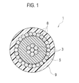
- FIG. 1 is a cross-sectional view of an micro coaxial cable according to the embodiment of the present invention.
- the micro coaxial cable 1 includes: a center conductor 3 that enables transfer of a signal; an insulator 5 that covers a periphery of the center conductor 3; an external conductor 8 as a shield that covers a periphery of the insulator 5; and a jacket 9 that covers a periphery of the external conductor 8.
- the insulator 5 is formed of a resin composition containing insulating resin, carbon black and fired pigment, and as the fired pigment, contains titanium (Ti), antimony (Sb) and chromium (Cr).
- a conductor corresponding to 46 to 40 AWG (American Wire Gauge) is used as the center conductor 3.
- the insulating resin is not particularly limited as long as the insulating resin concerned does not allow transmission of a laser beam and has insulating properties.
- fluorine resin for example, PFA resin made of a copolymer of tetrafluoroethylene (TFE) and perfluoroalkoxyethylene.
- loadings of the carbon black and the fired pigment into the insulating resin are set as follows: the carbon black is added by 0.8 to 1.2 mass parts with respect to 100 mass parts of the insulating resin; and the fired pigment is added by 4 to 12 mass parts with respect thereto.
- the carbon black is added by 0.8 to 1.2 mass parts with respect to 100 mass parts of the insulating resin, and the fired pigment is added by 4 to 6 mass parts with respect thereto.
- the fired pigment contains titanium (Ti), antimony (Sb) and chromium (Cr). And specifically, the fired pigment contains TiO 2 by 70 to 80 mass%, Sb 2 O 5 by 10 to 20 mass%, and Cr 2 O 3 by 4 to 10 mass% on the basis of total mass of the fired pigment.
- a film thickness of the insulator 5 is a film thickness to be usually embodied for a conductor with 46 to 40 AWG.
- the external conductor 8 is twisted in a laterally wound manner on such an outer periphery of the insulator 5.
- the jacket is not particularly limited as long as the jacket concerned has insulating properties.
- fluorine resin for example, PFA resin made of a copolymer of tetrafluoroethylene (TFE) and perfluoroalkoxyethylene.
- the resin composition for use in the insulator of the micro coaxial cable according to the embodiment can be used for a variety of usage purposes as below.
- a resin composition 1 was prepared, which was obtained by adding 1 mass part of the carbon black and 10 mass parts of the fired pigment to 100 mass parts of the PFA resin made of the copolymer of tetrafluoroethylene (TFE) and perfluoroalkoxyethylene and serving as a base material. Moreover, a composition ratio of the above-described components was changed as shown in Table 2, and resin compositions 2 to 4 were prepared.
- micro coaxial cables according to Example 2 and Comparative examples 1 and 2 were fabricated in a similar way to Example 1 except that resin compositions 2, 3 and 4 were used in place of the resin composition 1.
- the center conductor was exposed by removing the insulator by the CO 2 laser, and then the number of center conductors damaged among 40 pieces of the center conductors was counted, and the number of such damaged pieces was displayed by percent in accordance with the following expression.
- Damage % ⁇ on center conductor number of damaged pieces / 40 ⁇ 100 Exterior appearance of insulator: the damage on the center conductor and the insulator was observed by using a 30-power stereoscopic microscope. Then, the good one (the one free from the damage) was evaluated as “single circle”, and the failure one (which was damaged) was evaluated as "cross”.
- Withstand voltage a withstand voltage (dielectric voltage) test was performed between the center conductor and the external conductor.
- a withstand voltage test 40 pieces of the center conductors and the external conductors were individually soldered together in a lump, and a voltage applied thereto was raised from 100V until each of the micro coaxial cables turned to a failure state.
- a maximum voltage in this case was defined as the withstand voltage.
- Example 2 in which the PFA resin, the fired pigment (yellow) and the carbon black were blended with one another in a ratio (mass parts) of 100: 5: 1 exhibited the most excellent properties.
- the micro coaxial cable is provided, which does not damage the insulator or the center conductor at the time of processing the terminal end of the micro coaxial cable concerned by using the laser beam.
Landscapes
- Chemical & Material Sciences (AREA)
- Health & Medical Sciences (AREA)
- Chemical Kinetics & Catalysis (AREA)
- Medicinal Chemistry (AREA)
- Polymers & Plastics (AREA)
- Organic Chemistry (AREA)
- Physics & Mathematics (AREA)
- Spectroscopy & Molecular Physics (AREA)
- Communication Cables (AREA)
- Compositions Of Macromolecular Compounds (AREA)
- Organic Insulating Materials (AREA)
- Inorganic Insulating Materials (AREA)
- Insulated Conductors (AREA)
Abstract
Description
- The present invention relates to an micro coaxial cable and a laser beam shielding resin composition.
- In recent years, miniaturization/weight reduction and multifunctionalization of electronic instruments represented by cellular phones have been rapidly progressed. As properties required for an internal wiring material of the electronic instruments as described above, there are mentioned: that the internal wiring material should have a thin diameter; that the internal wiring material should be excellent in shielding properties; that the internal wiring material should be capable of high-speed signal transfer; and the like. Moreover, among the cellular phones, those have been increased, in each of which a cabinet on an LCD screen side and a cabinet on a main board side are connected to each other through a hinge. For such an internal wiring material that performs the signal transfer in the cellular phones, high repeated bending resistance is required.
- In order to cope with these requirements, an micro coaxial cable is used as the internal wiring material that performs the signal transfer in the cellular phones. The micro coaxial cable includes: a center conductor that enables the transfer of the signal; an insulator that is made of a resin composition and covers a periphery of the center conductor; an external conductor that serves as a shield and covers a periphery of the insulator; and a jacket that covers a periphery of the external conductor.
- In order to connect the micro coaxial cable to a connector, as shown in
FIG. 2 , it is necessary to expose tips of thecenter conductor 3, theinsulator 105 and theexternal conductor 8 by predetermined lengths. In the case of a usual cable, such tip exposure is performed by a mechanical method of cutting the cable by using a rotary blade or a chemical method of exposing the tips by using an etching material. However, when a wire diameter is small as in the micro coaxial cable, it is difficult to expose the tip of thecenter conductor 3 in accordance with such a conventional method. Therefore, by using laser beams, the tips of thecenter conductor 3, theinsulator 105 and theexternal conductor 8 are exposed. For example, at the time of cutting thejacket 9 and theinsulator 105, a CO2 laser (λ = 10. 6 µm) with a long wavelength is used, and at the time of cutting theexternal conductor 8 and thecenter conductor 3, a YAG laser (λ = 1065 nn) or an SHG laser (λ = 530 nm), which has a short wavelength, is used. - However, when the
external conductor 8 is attempted to be cut by irradiating the laser beam onto the microcoaxial cable 101, then as shown inFIG. 3 , the laser beam sometimes enters an inside of the coaxial cable from gaps among strands of theexternal conductors 8. In the case where theinsulator 105 is transparent, thelaser beam 105 transmits through theinsulator 105, and damages thecenter conductor 3. In the case where theinsulator 105 is a material likely to absorb the laser beam, theinsulator 105 is burnt and damaged. Moreover, at the time of irradiating the laser beam onto the microcoaxial cable 101, then as shown inFIG. 4 , a few strands of theexternal conductor 8 are cut to expose a part of theinsulator 105 in some case. The laser beam is not irradiated onto theexternal conductor 8 only once but irradiated thereonto several times. Accordingly, when the laser beam is irradiated again after a part of theinsulator 105 is damaged, even thecenter conductor 3 is damaged. - Therefore, an micro coaxial cable has been required, which does not cause damage on the
insulator 105 or thecenter conductor 3 at the time of cutting theexternal conductor 8 of the micro coaxial cable concerned by the YAG laser or the like. - As means for solving the above-described problem, in
Patent Literature 1, it is described that carbon black is added into the resin composition that composes the insulator. However, there has been room for improvement against inferiority in withstand voltage properties. -
- Patent Literature 1: Japanese Patent Laid-Open Publication No.
2005-25122 - It is an object of the present invention to provide an micro coaxial cable that does not damage an insulator or a center conductor at the time of processing a terminal end of the micro coaxial cable concerned by using the laser beam.
- According to a first aspect of the present invention is summarized to be an micro coaxial cable including: a center conductor that enables transfer of a signal; an insulator that covers a periphery of the center conductor; an external conductor as a shield that covers a periphery of the insulator; and a jacket that covers a periphery of the external conductor, wherein the insulator is formed of a resin composition containing insulating resin, carbon black and fired pigment, and as the fired pigment, contains titanium (Ti), antimony (Sb) and chromium (Cr) is provided.
- According to a second aspect of the present invention is summarized to be a laser beam shielding resin composition, wherein the laser beam shielding resin composition contains insulating resin, carbon black and fired pigment, and titanium (Ti), antimony (Sb) and chromium (Cr) are contained as the fired pigment is provided.
- In accordance with the present invention, the micro coaxial cable is provided, which does not damage the insulator or the center conductor at the time of processing the terminal end of the micro coaxial cable concerned by using the laser beam.
-
-
FIG. 1 is a cross-sectional view of an micro coaxial cable. -
FIG. 2 is a perspective view showing a state where a tip of a center conductor is exposed from the micro coaxial cable. -
FIG. 3 is a conceptual view (No. 1) explaining a cause by which the center conductor is damaged at a time of a laser process. -
FIG. 4 is a conceptual view (No. 2) explaining the cause by which the center conductor is damaged at the time of the laser process. -
FIG. 5 is a conceptual view (No. 1) of a manufacturing process of the micro coaxial cable. -
FIG. 6 is a conceptual view (No. 2) of the manufacturing process of the micro coaxial cable. -
FIG. 7 is a conceptual view (No. 3) of the manufacturing process of the micro coaxial cable. - A description is made below of the present invention by mentioning an embodiment; however, the present invention is not limited to the following embodiment. Note that the same or similar reference numerals are assigned to those having the same functions or similar functions in the drawings, and a description thereof is omitted.
-
FIG. 1 is a cross-sectional view of an micro coaxial cable according to the embodiment of the present invention. The microcoaxial cable 1 includes: acenter conductor 3 that enables transfer of a signal; aninsulator 5 that covers a periphery of thecenter conductor 3; anexternal conductor 8 as a shield that covers a periphery of theinsulator 5; and ajacket 9 that covers a periphery of theexternal conductor 8. Theinsulator 5 is formed of a resin composition containing insulating resin, carbon black and fired pigment, and as the fired pigment, contains titanium (Ti), antimony (Sb) and chromium (Cr). - Preferably, a conductor corresponding to 46 to 40 AWG (American Wire Gauge) is used as the
center conductor 3. - The insulating resin is not particularly limited as long as the insulating resin concerned does not allow transmission of a laser beam and has insulating properties. However, there can be used fluorine resin, for example, PFA resin made of a copolymer of tetrafluoroethylene (TFE) and perfluoroalkoxyethylene.
- Preferably, loadings of the carbon black and the fired pigment into the insulating resin are set as follows: the carbon black is added by 0.8 to 1.2 mass parts with respect to 100 mass parts of the insulating resin; and the fired pigment is added by 4 to 12 mass parts with respect thereto. This is because the
insulator 5 or thecenter conductor 3 is not damaged at the time of processing a terminal end of the microcoaxial cable 1 by using the laser beam. Moreover, from a viewpoint of enhancing insulating/withstand voltage properties between thecenter conductor 3 and theexternal conductor 8, preferably, the carbon black is added by 0.8 to 1.2 mass parts with respect to 100 mass parts of the insulating resin, and the fired pigment is added by 4 to 6 mass parts with respect thereto. - Preferably, the fired pigment contains titanium (Ti), antimony (Sb) and chromium (Cr). And specifically, the fired pigment contains TiO2 by 70 to 80 mass%, Sb2O5 by 10 to 20 mass%, and Cr2O3 by 4 to 10 mass% on the basis of total mass of the fired pigment.
- Preferably, a film thickness of the
insulator 5 is a film thickness to be usually embodied for a conductor with 46 to 40 AWG. Preferably, theexternal conductor 8 is twisted in a laterally wound manner on such an outer periphery of theinsulator 5. - The jacket is not particularly limited as long as the jacket concerned has insulating properties. However, there can be used fluorine resin, for example, PFA resin made of a copolymer of tetrafluoroethylene (TFE) and perfluoroalkoxyethylene.
-
- (A) An
extruder 11 as shown inFIG. 5 is prepared. Theextruder 11 includes: anextruder body 11a; ahopper 18 provided on an upper portion of theextruder body 11a; and adice 13 provided on a side portion of theextruder body 11a, and further, includesspools center conductor 3, which are arranged while sandwiching theextruder body 11a therebetween. Thedice 13 is composed so that thecenter conductor 3 can pass through an inside of thedice 13 concerned. -
- (B) Then, the resin composition (5) poured from the
hopper 18 is heated and kneaded in theextruder body 11a. Thereafter, while extruding the resin composition (5) from thedice 13, thecenter conductor 3 is wound up so as to pass through the inside of thedice 13, whereby theinsulator 5 is coated on the periphery of thecenter conductor 3, and acable 1A is obtained. -
- (C) As shown in
FIG. 6 , by aconductor winder 15, theexternal conductor 8 is wound in a spiral shape on the outer periphery of theinsulator 5 of thecable 1A. Then, acable 1B thus shielded is wound up by aspool 16a. -
- (D) In a similar way to the step (A), the jacket is extruded and coated on an outer periphery of the
cable 1B by using a device inFIG. 7 . In such a manner as described above, the microcoaxial cable 1 inFIG. 1 is manufactured. - As above, the description has been made of the present invention by the embodiment; however, it should not be understood that the description and the drawings, which form a part of this disclosure, limit this invention. From this disclosure, varieties of alternative embodiments, examples and application technologies will be apparent for those skilled in the art.
- For example, as a laser beam shielding resin composition, the resin composition for use in the insulator of the micro coaxial cable according to the embodiment can be used for a variety of usage purposes as below.
-
- (1) The resin composition can be used as an insulator of a cable thicker than the micro coaxial cable. In such a way, the external conductor can be cut by using the laser without damaging the center conductor.
-
- (2) The micro coaxial cable according to the invention is composed of two layers of conductors, which are the center conductor and the external conductor, and has a structure in which the conductors are concentric with each other. However, in the other one than the coaxial cable, for example, in the one composed of two or more layers of metal flat plates (that is, for example, an FPC: flexible printed circuit), at the time of cutting a first layer of the metal, the laser beam shielding resin composition is laid as an underlying base, whereby the metal as a lower layer is prevented from being damaged.
-
- (3) In the case where the metal is placed in an environment of being exposed to light close to the laser beam in terms of the wavelength, the laser beam shielding resin composition is applied to a surface of the metal concerned, whereby the damage on the metal can be prevented.
- As described above, naturally, the present invention incorporates varieties of embodiments and the like, which are not described herein. Hence, the technical scope of the present invention is determined only by the invention specifying items according to the scope of claims reasonable from the above description.
- A
resin composition 1 was prepared, which was obtained by adding 1 mass part of the carbon black and 10 mass parts of the fired pigment to 100 mass parts of the PFA resin made of the copolymer of tetrafluoroethylene (TFE) and perfluoroalkoxyethylene and serving as a base material. Moreover, a composition ratio of the above-described components was changed as shown in Table 2, and resin compositions 2 to 4 were prepared. - An insulator made of the
resin composition 1, the external conductor and the jacket were sequentially provided on the outer periphery of the center conductor corresponding to 46 AWG in conformity with the manufacturing method of the micro coaxial cable according to the embodiment, whereby an micro coaxial cable according to Example 1 was fabricated. Moreover, micro coaxial cables according to Example 2 and Comparative examples 1 and 2 were fabricated in a similar way to Example 1 except thatresin compositions 2, 3 and 4 were used in place of theresin composition 1. - For the micro coaxial cables according to Examples 1 and 2 and Comparative examples 1 and 2, damages on the center conductors, exterior appearances of the insulators and withstand voltages at the time of cutting the jackets and the external conductors by individually using the YAG laser and the SHG laser were observed and evaluated in accordance with the following evaluation criteria. Results thus obtained are shown in Table 1 in summary. [Table 1]
table 1 Composition Ratio (mass parts) YAG Laser SHG Laser Comprehensive evaluation Damage on center conductor Exterior appearance of insulator Withstand voltage[V] Comprehensive evaluation Damage on center conductor Exterior appearance of insulator Withstand voltage[V] Example 1 Resin Composition 1PFA : YE : BK=100 : 10 : 1 ○ 0.0% ○ 600 ○ 0.0% ○ 500 Example 2 Resin Composition 2 PFA : YE : BK=100 : 5 : 1 ⊚ 0.0% ○ 700 ⊚ 0.0% ○ 625 Comparative Example 1 Resin Composition 3PFA : BK=100 : 1 ○ 0.0% ○ 567 ○ 0.0% ○ 480 Comparative Example 2 Resin Composition 4 PFA : YE=8 : 1 × 5.8% ○ - × 2.5% ○ 460 Remarks Double circle(⊚): extremely good, Single circle(○) good, Cross (×) : failure PFA: PFA resin, BK: carbon black. YE: fired pigment - Damage on center conductor: the center conductor was exposed by removing the insulator by the CO2 laser, and then the number of center conductors damaged among 40 pieces of the center conductors was counted, and the number of such damaged pieces was displayed by percent in accordance with the following expression.
-

Exterior appearance of insulator: the damage on the center conductor and the insulator was observed by using a 30-power stereoscopic microscope. Then, the good one (the one free from the damage) was evaluated as "single circle", and the failure one (which was damaged) was evaluated as "cross". - Withstand voltage: a withstand voltage (dielectric voltage) test was performed between the center conductor and the external conductor. For the withstand voltage test, 40 pieces of the center conductors and the external conductors were individually soldered together in a lump, and a voltage applied thereto was raised from 100V until each of the micro coaxial cables turned to a failure state. A maximum voltage in this case was defined as the withstand voltage.
- As comprehensive evaluations, the extremely good ones were evaluated to be "double circle", the good ones were evaluated to be "single circle", and the failure one was evaluated to be "cross".
- In accordance with Table 1, in Comparative example 2 in which fired pigment (yellow) was added to the PFA resin, the damage occurred on the center conductor. In Comparative example 1 in which carbon black was mixed into the PFA resin corresponding to the invention of
Patent Literature 1, though the center conductor and the insulator were not damaged, a value of the withstand voltage was approximately 500V, resulting in a little inferiority in the withstand voltage properties. - Meanwhile, in Examples 1 and 2, in each of which the fired pigment (yellow) was added besides the carbon black, there was no damage on the center conductor or the exterior appearance of the insulator, and the withstand voltage properties were good. In particular, Example 2 in which the PFA resin, the fired pigment (yellow) and the carbon black were blended with one another in a ratio (mass parts) of 100: 5: 1 exhibited the most excellent properties.
- The reason why the resistance to the laser beam was enhanced by mixing the fired pigment (yellow) besides the carbon black is not certain. However, in the case of blending only the carbon black, it is considered that the insulator only absorbs a part of light, and that the rest thereof transmits therethrough. Meanwhile, it is considered that an effect of reflecting the laser beam in the insulator is obtained by mixing the fired pigment (yellow).
- This application involves a priority claim based on a Japanese patent application previously made by the same applicant, that is, on Japanese Patent Laid-Open Publication No.
2009-109747 (filed on April 28, 2009 - In accordance with the present invention, the micro coaxial cable is provided, which does not damage the insulator or the center conductor at the time of processing the terminal end of the micro coaxial cable concerned by using the laser beam.
Claims (8)
- An micro coaxial cable comprising:a center conductor that enables transfer of a signal;an insulator that covers a periphery of the center conductor;an external conductor as a shield that covers a periphery of the insulator; anda jacket that covers a periphery of the external conductor,wherein the insulator is formed of a resin composition containing insulating resin, carbon black and fired pigment,the fired pigment contains titanium (Ti), antimony (Sb) and chromium (Cr).
- The micro coaxial cable according to claim 1,
wherein the insulator contains 0.8 to 1.2 mass parts of the carbon black and 4 to 6 mass parts of the fired pigment with respect to 100 mass parts of the insulating resin. - The micro coaxial cable according to claim 1,
wherein the fired pigment consists essentially of TiO2 by 70 to 80 mass%, Sb2O5 by 10 to 20 mass%, and Cr2O3 by 4 to 10 mass% on the basis of total mass of the fired pigment. - The micro coaxial cable according to claim 1, wherein the insulating resin is fluorine resin.
- A laser beam shielding resin composition,
wherein the laser beam shielding resin composition contains insulating resin, carbon black and fired pigment, and
the fired pigment contains titanium (Ti), antimony (Sb) and chromium (Cr). - The laser beam shielding resin composition according to claim 5,
wherein the laser beam shielding resin composition contains 0.8 to 1.2 mass parts of the carbon black and 4 to 6 mass parts of the fired pigment with respect to 100 mass parts of the insulating resin. - The laser beam shielding resin composition according to claim 5,
wherein the fired pigment consists essentially of TiO2 by 70 to 80 mass%, Sb2O5 by 10 to 20 mass%, and Cr2O3 by 4 to 10 mass% on the basis of total mass of the fired pigment. - The laser beam shielding resin composition according to claim 5, wherein the insulating resin is fluorine resin.
Applications Claiming Priority (2)
| Application Number | Priority Date | Filing Date | Title |
|---|---|---|---|
| JP2009109747A JP4619444B2 (en) | 2009-04-28 | 2009-04-28 | Ultrafine coaxial cable and resin composition for laser light shielding |
| PCT/JP2010/056990 WO2010125944A1 (en) | 2009-04-28 | 2010-04-20 | Micro coaxial cable and resin composition for shielding laser light |
Publications (2)
| Publication Number | Publication Date |
|---|---|
| EP2426675A1 true EP2426675A1 (en) | 2012-03-07 |
| EP2426675A4 EP2426675A4 (en) | 2013-06-26 |
Family
ID=43032098
Family Applications (1)
| Application Number | Title | Priority Date | Filing Date |
|---|---|---|---|
| EP10769643.7A Withdrawn EP2426675A4 (en) | 2009-04-28 | 2010-04-20 | Micro coaxial cable and resin composition for shielding laser light |
Country Status (7)
| Country | Link |
|---|---|
| US (1) | US8530741B2 (en) |
| EP (1) | EP2426675A4 (en) |
| JP (1) | JP4619444B2 (en) |
| KR (1) | KR20120024638A (en) |
| CN (1) | CN102414762A (en) |
| TW (1) | TW201110151A (en) |
| WO (1) | WO2010125944A1 (en) |
Families Citing this family (9)
| Publication number | Priority date | Publication date | Assignee | Title |
|---|---|---|---|---|
| US8850702B2 (en) * | 2009-05-26 | 2014-10-07 | Cardiac Pacemakers, Inc. | Cable consolidation with a laser |
| AU2010351384B2 (en) * | 2010-04-23 | 2016-06-09 | Prysmian S.P.A. | Shielding of high voltage cables |
| JP5356454B2 (en) * | 2011-06-01 | 2013-12-04 | 日星電気株式会社 | coaxial cable |
| JP5974992B2 (en) * | 2013-07-10 | 2016-08-23 | 日立金属株式会社 | Coaxial cable for high-frequency signal transmission |
| KR101633313B1 (en) | 2014-09-11 | 2016-06-24 | 대우조선해양 주식회사 | Cable Mounting Method for Ship |
| BR112019020148A2 (en) | 2017-04-13 | 2020-05-05 | Cadila Healthcare Limited | peptide |
| JP6756692B2 (en) * | 2017-11-07 | 2020-09-16 | 日立金属株式会社 | Insulated wire |
| CN109102960A (en) * | 2018-07-26 | 2018-12-28 | 浙江兆龙互连科技股份有限公司 | The resistant to bending superfine coaxial signal transmission cable of one kind and production method |
| CN114709684A (en) * | 2022-03-14 | 2022-07-05 | 吉林省中赢高科技有限公司 | Novel shielding material's connector assembly and vehicle |
Family Cites Families (13)
| Publication number | Priority date | Publication date | Assignee | Title |
|---|---|---|---|---|
| JPS5749106A (en) * | 1980-09-05 | 1982-03-20 | Nippon Electric Co | Insulating paste composition |
| DE3604317A1 (en) * | 1986-02-13 | 1987-08-20 | Basf Lacke & Farben | TEMPERATURE-STABLE RUTILE MIXED-PHASE PIGMENTS |
| US6906257B2 (en) * | 2001-01-29 | 2005-06-14 | Honeywell International Inc. | Metallic coated dielectric substrates |
| JP4141818B2 (en) * | 2002-12-06 | 2008-08-27 | 株式会社フジクラ | Ultra-fine coaxial cable and manufacturing method thereof |
| US7438748B2 (en) * | 2003-02-18 | 2008-10-21 | Union Carbide Chemicals & Plastics Technology Llc | Flame retardant composition |
| JP2005025122A (en) | 2003-07-03 | 2005-01-27 | Sony Corp | OUTPUT DATA CONTROL DEVICE, OUTPUT DATA CONTROL METHOD, AND COMPUTER PROGRAM |
| WO2005023924A1 (en) * | 2003-09-05 | 2005-03-17 | Union Carbide Chemicals & Plastics Technology Corporation | Flame retardant composition with excellent processability |
| JP4352935B2 (en) * | 2004-03-03 | 2009-10-28 | 住友電気工業株式会社 | Shielded cable and terminal forming method thereof |
| JP4702224B2 (en) * | 2006-01-31 | 2011-06-15 | 日立電線株式会社 | Shielded cable and end processing method thereof |
| US7928168B2 (en) * | 2007-03-23 | 2011-04-19 | Sabic Innovative Plastics Ip B.V. | White light-shielding compositions and articles comprising same |
| JP5180521B2 (en) * | 2007-06-15 | 2013-04-10 | 日立電線ファインテック株式会社 | Signal transmission cable and multi-core cable |
| US20090022462A1 (en) * | 2007-07-20 | 2009-01-22 | Polymer Products Company, Inc. | Fire resistant jacket composition for electrical coaxial and fiber optic cable |
| JP5082771B2 (en) | 2007-10-30 | 2012-11-28 | ヤマハ株式会社 | Performance terminal controller and program |
-
2009
- 2009-04-28 JP JP2009109747A patent/JP4619444B2/en not_active Expired - Fee Related
-
2010
- 2010-04-20 CN CN2010800191441A patent/CN102414762A/en active Pending
- 2010-04-20 KR KR1020117027922A patent/KR20120024638A/en not_active Ceased
- 2010-04-20 EP EP10769643.7A patent/EP2426675A4/en not_active Withdrawn
- 2010-04-20 WO PCT/JP2010/056990 patent/WO2010125944A1/en not_active Ceased
- 2010-04-27 TW TW099113328A patent/TW201110151A/en unknown
-
2011
- 2011-10-26 US US13/281,926 patent/US8530741B2/en not_active Expired - Fee Related
Also Published As
| Publication number | Publication date |
|---|---|
| JP4619444B2 (en) | 2011-01-26 |
| TW201110151A (en) | 2011-03-16 |
| CN102414762A (en) | 2012-04-11 |
| JP2010257899A (en) | 2010-11-11 |
| WO2010125944A1 (en) | 2010-11-04 |
| KR20120024638A (en) | 2012-03-14 |
| EP2426675A4 (en) | 2013-06-26 |
| US20120037394A1 (en) | 2012-02-16 |
| US8530741B2 (en) | 2013-09-10 |
Similar Documents
| Publication | Publication Date | Title |
|---|---|---|
| US8530741B2 (en) | Micro coaxial cable and laser beam shielding resin composition | |
| JP5180521B2 (en) | Signal transmission cable and multi-core cable | |
| TWI419178B (en) | Differential transmission signal cable and composite cable containing the same | |
| US7291786B2 (en) | Differential signal transmission cable | |
| KR101415477B1 (en) | Paste for electrostatic protection, electrostatic protection component, and method for producing same | |
| EP0898286B1 (en) | Insulated wire | |
| JP2001524747A (en) | Surface mountable electrical device including PTC and fusible element | |
| CN102017018A (en) | Electrical wire and method for producing same | |
| DE2808900A1 (en) | ELECTRIC CABLE | |
| JP3994698B2 (en) | Semi-flexible micro coaxial cable and its terminal connection method | |
| US20140027151A1 (en) | Shielded cable | |
| DE102021125794A1 (en) | Twisted wire and cable containing it | |
| TW200805404A (en) | A flat cable | |
| KR20140001728A (en) | Insulated wire, coaxial cable and multiconductor cable | |
| JP4352935B2 (en) | Shielded cable and terminal forming method thereof | |
| JP4702224B2 (en) | Shielded cable and end processing method thereof | |
| US20250273362A1 (en) | Insulated electric wire and information transmission cable | |
| JP2001084850A (en) | Terminal-worked coaxial cable and its manufacture | |
| EP3731242B1 (en) | Cable | |
| JP5356454B2 (en) | coaxial cable | |
| CN101110283A (en) | Coaxial cable and multi-core coaxial cable | |
| JP2005050622A (en) | Terminal processed cable and its manufacturing method | |
| JP2005038617A (en) | Connection structure of cable harness with connector for high-speed differential signal transmission | |
| JP2012119197A (en) | Insulation wire for transmission cable and transmission cable | |
| JP2025165621A (en) | Insulated wire and cable |
Legal Events
| Date | Code | Title | Description |
|---|---|---|---|
| PUAI | Public reference made under article 153(3) epc to a published international application that has entered the european phase |
Free format text: ORIGINAL CODE: 0009012 |
|
| 17P | Request for examination filed |
Effective date: 20111128 |
|
| AK | Designated contracting states |
Kind code of ref document: A1 Designated state(s): AT BE BG CH CY CZ DE DK EE ES FI FR GB GR HR HU IE IS IT LI LT LU LV MC MK MT NL NO PL PT RO SE SI SK SM TR |
|
| DAX | Request for extension of the european patent (deleted) | ||
| A4 | Supplementary search report drawn up and despatched |
Effective date: 20130524 |
|
| RIC1 | Information provided on ipc code assigned before grant |
Ipc: H01B 11/18 20060101AFI20130517BHEP Ipc: H01B 3/00 20060101ALI20130517BHEP Ipc: H01R 43/28 20060101ALI20130517BHEP Ipc: C08K 3/22 20060101ALI20130517BHEP Ipc: H01B 3/44 20060101ALI20130517BHEP Ipc: C08K 3/04 20060101ALI20130517BHEP Ipc: C08L 101/00 20060101ALI20130517BHEP |
|
| STAA | Information on the status of an ep patent application or granted ep patent |
Free format text: STATUS: THE APPLICATION HAS BEEN WITHDRAWN |
|
| 18W | Application withdrawn |
Effective date: 20130722 |