EP2426608B1 - System for maintaining a large number of handheld electronic devices - Google Patents
System for maintaining a large number of handheld electronic devices Download PDFInfo
- Publication number
- EP2426608B1 EP2426608B1 EP11191010.5A EP11191010A EP2426608B1 EP 2426608 B1 EP2426608 B1 EP 2426608B1 EP 11191010 A EP11191010 A EP 11191010A EP 2426608 B1 EP2426608 B1 EP 2426608B1
- Authority
- EP
- European Patent Office
- Prior art keywords
- usb hub
- heds
- port
- computer
- usb
- Prior art date
- Legal status (The legal status is an assumption and is not a legal conclusion. Google has not performed a legal analysis and makes no representation as to the accuracy of the status listed.)
- Not-in-force
Links
Images




Classifications
-
- G—PHYSICS
- G06—COMPUTING OR CALCULATING; COUNTING
- G06F—ELECTRIC DIGITAL DATA PROCESSING
- G06F13/00—Interconnection of, or transfer of information or other signals between, memories, input/output devices or central processing units
- G06F13/14—Handling requests for interconnection or transfer
-
- G—PHYSICS
- G11—INFORMATION STORAGE
- G11B—INFORMATION STORAGE BASED ON RELATIVE MOVEMENT BETWEEN RECORD CARRIER AND TRANSDUCER
- G11B33/00—Constructional parts, details or accessories not provided for in the other groups of this subclass
- G11B33/12—Disposition of constructional parts in the apparatus, e.g. of power supply, of modules
- G11B33/125—Disposition of constructional parts in the apparatus, e.g. of power supply, of modules the apparatus comprising a plurality of recording/reproducing devices, e.g. modular arrangements, arrays of disc drives
- G11B33/126—Arrangements for providing electrical connections, e.g. connectors, cables, switches
-
- G—PHYSICS
- G06—COMPUTING OR CALCULATING; COUNTING
- G06F—ELECTRIC DIGITAL DATA PROCESSING
- G06F13/00—Interconnection of, or transfer of information or other signals between, memories, input/output devices or central processing units
- G06F13/38—Information transfer, e.g. on bus
-
- G—PHYSICS
- G06—COMPUTING OR CALCULATING; COUNTING
- G06F—ELECTRIC DIGITAL DATA PROCESSING
- G06F13/00—Interconnection of, or transfer of information or other signals between, memories, input/output devices or central processing units
- G06F13/38—Information transfer, e.g. on bus
- G06F13/40—Bus structure
- G06F13/4004—Coupling between buses
- G06F13/4022—Coupling between buses using switching circuits, e.g. switching matrix, connection or expansion network
-
- G—PHYSICS
- G11—INFORMATION STORAGE
- G11B—INFORMATION STORAGE BASED ON RELATIVE MOVEMENT BETWEEN RECORD CARRIER AND TRANSDUCER
- G11B21/00—Head arrangements not specific to the method of recording or reproducing
- G11B21/02—Driving or moving of heads
- G11B21/10—Track finding or aligning by moving the head ; Provisions for maintaining alignment of the head relative to the track during transducing operation, i.e. track following
-
- B—PERFORMING OPERATIONS; TRANSPORTING
- B62—LAND VEHICLES FOR TRAVELLING OTHERWISE THAN ON RAILS
- B62B—HAND-PROPELLED VEHICLES, e.g. HAND CARTS OR PERAMBULATORS; SLEDGES
- B62B2202/00—Indexing codes relating to type or characteristics of transported articles
- B62B2202/56—Computers; Screens
-
- G—PHYSICS
- G06—COMPUTING OR CALCULATING; COUNTING
- G06F—ELECTRIC DIGITAL DATA PROCESSING
- G06F2213/00—Indexing scheme relating to interconnection of, or transfer of information or other signals between, memories, input/output devices or central processing units
- G06F2213/40—Bus coupling
- G06F2213/4002—Universal serial bus hub with a single upstream port
Definitions
- the present invention relates to a system for maintaining a large number of Handheld Electronic Devices (HEDs).
- HEDs Handheld Electronic Devices
- Portable handheld devices that are capable of storing content such as music and video have recently become popular.
- devices such as the iPODTM from Apple are popular devices that are commonly used to store music and/or video files. The music may then be played on demand either through earphones, or through another stereo device via a docking station.
- HED Handheld Electronic Device
- the term "Handheld Electronic Device or (HED)" will be used to refer to a portable and handheld digital electronic device for recording, organizing, transmitting, manipulating and reviewing text, data, audio, image, and video files.
- HEDs and other HEDs were initially made popular in connection with users that wanted to be able to have a portable music library, such HEDs are now being used for other purposes.
- museums are starting to load audio and/or audio/video museum tours on HEDs such as iPODs so that users can listen to and/or watch a guided program as they proceed through the museum.
- guided programs are commonly used to enable a person knowledgeable about art to narrate a guided tour one time, and then enable museum patrons to obtain the benefit of the guided tour at a later time by listening to the pre-recorded guided tour.
- HEDs such as iPODs
- a conference may provide a conference attendee with a HED to provide the conference attendees with information about the conference.
- a resort may provide a person with a HED when the person arrives at the resort to enable the person to listen to a program about the resort.
- USB Universal Serial Bus
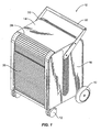
- Fig. 1 illustrates, for reference only, an embodiment of a cart 10 for maintaining a large number of Handheld Electronic Devices (HEDs).
- the cart generally is formed as a cabinet having wheels 12 that are configured to enable the cart to be mobile.
- the wheels may be castors such as the front wheels shown in Fig. 1 or may be directionally fixed wheels such as the rear wheels shown in Fig. 1 . Other types of wheels may be used as well.
- the interior of the cart is enclosed by a skin including a top panel 14, side panels 16, a back panel 18 (see Fig.2 ), and a roll-away panel 20 configured to slide in a channel 22 that extends from the bottom front edge 24 of the cart 10 to the rear bottom edge 26 of the cart 10.
- the roll-away panel slides along the channel 22 from a front position in which the front of the cart is closed by the roll-away panel, to a back position in which the roll-away panel is located in the channel along the rear side of the cart.
- the front of the cart may be opened as shown in Fig. 3 .
- the roll-away panel may be formed from a series of interlocking slats that are flexibly coupled to one another along their length (or at defined positions along their length) to enable the slats to pivot longitudinally relative to each other. Similar panels formed from multiple slats have been used in desks such as roll-top desks, in which wooden slats are used to enclose a top area of the desk.
- the slats in the cart shown in Fig. 1 may be made of plastic, metal, or a combination of materials depending on the particular implementation of the cart and the apparatus is not limited to the particular materials used to implement the roll-away panel of the cart.
- the top panel 14 is basically flat, with the exception of a front lip 28 and a rear lip 30.
- the front and rear lips are configured to define a top area on which a laptop computer or other computer may be placed when connecting to the handheld electronic devices contained within the cart 10.
- the front and rear lips enable the top area to be defined such that objects placed on the top of the cart are less likely to fall off of the top.
- the cart may be provided with a handle 32 to enable a person to push/pull the cart when it is necessary to move the cart.
- the cart is not limited to the particular handle structure shown in Fig. 1 , as many different handle structures may be used to implement embodiments of the apparatus.
- the rear panel 18, shown in greater detail in Fig. 2 may be provided with one or more sets of hooks 34 designed to hold power cords and/or hooks 36 designed to computer cables.
- a 9 foot long USB cable having two male ends (Type A male, Type B male) may be provided to interconnect each drawer with a laptop computer or desktop computer stored in the cart or placed on top of the cart.
- the cable can be unwound from the hooks and plugged into a computer to enable the computer to connect to HEDs stored within the cart and connected to the USB hub that forms part of the drawer.
- the USB hub aspect is described in greater detail below.
- Other cables may be used as well and the apparatus is not limited to use with particular USB cables.
- an on/off switch 38 may also be provided to enable the cart to be plugged into a wall outlet and then selectively turned on/off to enable the operator to determine when the HEDs stored within the cart should be charged.
- the channel 22 may be integral with the frame forming part of the structural support of the cart or may be a separate component that is connected to a supporting frame.
- a structural frame for a cart such as the cart shown in Fig. 1
- the apparatus is not limited to any particular frame structure.
- Fig. 3 shows a portion of the frame structure 40 configured to provide a racking system to hold one or more drawers which are described in greater detail below.
- the channel 22, in this embodiment, is thus connected to the side panel 16, although the apparatus is not limited to this particular embodiment.
- Fig. 3 shows the internal structure of the cart.
- the cart may contain one or more drawers 42, each of which is configured to hold multiple HEDs.
- the embodiment shown in Fig. 3 has two drawers, however the cart may have a larger or smaller number of drawers depending on the particular needs of the institution that has ordered the cart.
- the cart may also have one or more shelves 44 containing dividers 46 to enable one or more laptop computers to also be stored in the cart 10.
- a power charging strip may be provided in the cart to enable the computers to be plugged in to charge while stored in the cart 10.
- the drawers 42 are disposed on glides 48 that will enable the drawer to extend out of the front opening of the computer cart. Providing drawers that extend in this manner facilitates placement of the HEDs into the cart. Additional details of the drawer structure are provided in greater detail below.
- the cart may be designed to enable multiple HEDs to be updated with new information, such as from a laptop computer, and to also enable the multiple HEDs to be recharged while stored in the cart.
- new information such as from a laptop computer
- Figs 5 and 6 illustrate an example drawer structure that may be used as the drawers 42 in cart 10.
- the drawer includes an edge band 50 defining a perimeter of the drawer. Holes 52 may be formed in the edge band 50 to enable the drawer to be attached to the glides 48. Other methods of attaching the glides may be used as well.
- the drawer may also include a bottom plate (not shown) defining a bottom of the drawer so that things placed within the drawer will not fall out of the drawer.
- the divider structure (described below) may be connected to the edge band and define the bottom of the drawer.
- a divider structure 54 is included in the drawer 42 to define individual compartments sized to hold Handheld Electronic Devices (HEDs).
- the divider structure may be implemented using a soft material such as foam or other cushioning material that will cushion the HEDs while they are maintained in the drawer to minimize the amount of jarring that is transferred from the cart to the HEDs.
- Example HEDs include MP-3 players such as iPOD TM HEDs available from Apple Computer Corp. and other types of HEDs. As new HEDs are developed, differently sized dividers may be provided to securely hold the HEDs so that they may be retained within the drawer in a safe and secure manner.
- a central area of the drawer 56 contains an electrical circuit board 58 shown in Fig. 6 , to which the HEDs may be connected when placed in the drawer.
- the electrical circuit board 58 may be covered by a cover 60 (made of plastic, metal, or another material) to prevent accidental contact by a user.
- a rear enclosed area of the drawer may contain the power supply components, such as a power transformer, that may be used to step down the line current coming into the cart 10 from a wall outlet, and to condition the power for transmission to the circuit board. Power supplies are well known in the art and the cart is not limited to the use of a particular type of power supply.
Landscapes
- Engineering & Computer Science (AREA)
- Theoretical Computer Science (AREA)
- Physics & Mathematics (AREA)
- General Engineering & Computer Science (AREA)
- General Physics & Mathematics (AREA)
- Mathematical Physics (AREA)
- Computer Hardware Design (AREA)
- Information Transfer Systems (AREA)
- Power Sources (AREA)
- Charge And Discharge Circuits For Batteries Or The Like (AREA)
Description
- The present invention relates to a system for maintaining a large number of Handheld Electronic Devices (HEDs).
- Portable handheld devices that are capable of storing content such as music and video have recently become popular. For example, devices such as the iPOD™ from Apple are popular devices that are commonly used to store music and/or video files. The music may then be played on demand either through earphones, or through another stereo device via a docking station. As used herein, the term "Handheld Electronic Device or (HED)" will be used to refer to a portable and handheld digital electronic device for recording, organizing, transmitting, manipulating and reviewing text, data, audio, image, and video files.
- Although iPODs and other HEDs were initially made popular in connection with users that wanted to be able to have a portable music library, such HEDs are now being used for other purposes. For example, museums are starting to load audio and/or audio/video museum tours on HEDs such as iPODs so that users can listen to and/or watch a guided program as they proceed through the museum. Such guided programs are commonly used to enable a person knowledgeable about art to narrate a guided tour one time, and then enable museum patrons to obtain the benefit of the guided tour at a later time by listening to the pre-recorded guided tour.
- In addition to museums, other forums are also beginning to use HEDs such as iPODs to provide users with content. For example, a conference may provide a conference attendee with a HED to provide the conference attendees with information about the conference. Similarly, a resort may provide a person with a HED when the person arrives at the resort to enable the person to listen to a program about the resort.
- As companies, museums, individuals, and other institutions start to collect large numbers of HEDs, the manner in which the HEDs are maintained becomes important. For example, if a museum would like to open a new exhibit and provide a new guided program for the new exhibit, the museum will need to load new content onto their HEDs. Similarly, the museum will need to recharge the HED batteries periodically to enable the HEDs to be capable of functioning as the users roam throughout the museum. Accordingly, it would be desirable to provide a system that would enable users to maintain a large number of Handheld Electronic Devices.
UK patent application number 2352540 A US patent application publication number 2005/216620 A1 describes a similar circuit which will enable a keyboard and mouse to be shared between host computers, in which controllers are provided to emulate the keyboard and mouse when not connected to the host computer to reduce switching time associated with switching peripherals between computers. - According to a first aspect of the present invention, there is provided a multi-port Universal Serial Bus (USB) hub as claimed in Claim 1. Other embodiments of the invention are specified in the appended claims.
- The present invention is illustrated by way of example in the following drawings in which like references indicate similar elements. The following drawings disclose various embodiments of the present invention for purposes of illustration only and are not intended to limit the scope of the invention as claimed. For purposes of clarity, not every component may be labeled in every figure. In the figures:
-
Fig. 1 is a front perspective view of a cart for maintaining a large number of Handheld Electronic Devices (HEDs) -
Fig. 2 is a back perspective view of the cart ofFig. 1 ; -
Fig. 3 is a front perspective view of the cart ofFig. 1 with the roll-away front panel opened to access drawers configured to contain the HEDs; -
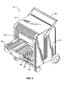
Fig. 4 is a front perspective view of the cart ofFig. 3 with one drawer extended; -
Fig. 5 is a front perspective view of a drawer removed from the cart; -
Fig. 6 is a front perspective view of a drawer ofFig. 5 with a protective cover removed to reveal an electronic circuit board in the interior of the drawer; -
Fig. 7 is a top plan view of the drawer ofFig. 6 ; -
Figs. 8 and 9 show an embodiment of anelectrical circuit board 58 configured to enable 20 HEDs to be charged and synchronized according to an embodiment of the invention; and -
Fig. 10 illustrates a cable that may be used to interconnect a HED with the electrical circuit board. - The following detailed description sets forth numerous specific details to provide a thorough understanding of the invention. However, those skilled in the art will appreciate that the invention may be practiced without these specific details. In other instances, well-known methods, procedures, components, and dimensions have not been described in detail so as not to obscure the invention.
-
Fig. 1 illustrates, for reference only, an embodiment of acart 10 for maintaining a large number of Handheld Electronic Devices (HEDs). As shown inFig. 1 , the cart generally is formed as acabinet having wheels 12 that are configured to enable the cart to be mobile. The wheels may be castors such as the front wheels shown inFig. 1 or may be directionally fixed wheels such as the rear wheels shown inFig. 1 . Other types of wheels may be used as well. - The interior of the cart is enclosed by a skin including a
top panel 14,side panels 16, a back panel 18 (seeFig.2 ), and a roll-away panel 20 configured to slide in achannel 22 that extends from the bottomfront edge 24 of thecart 10 to therear bottom edge 26 of thecart 10. To open the cart, the roll-away panel slides along thechannel 22 from a front position in which the front of the cart is closed by the roll-away panel, to a back position in which the roll-away panel is located in the channel along the rear side of the cart. By moving the roll-away panel along the channel the front of the cart may be opened as shown inFig. 3 . - The roll-away panel may be formed from a series of interlocking slats that are flexibly coupled to one another along their length (or at defined positions along their length) to enable the slats to pivot longitudinally relative to each other. Similar panels formed from multiple slats have been used in desks such as roll-top desks, in which wooden slats are used to enclose a top area of the desk. The slats in the cart shown in
Fig. 1 may be made of plastic, metal, or a combination of materials depending on the particular implementation of the cart and the apparatus is not limited to the particular materials used to implement the roll-away panel of the cart. - The
top panel 14 is basically flat, with the exception of afront lip 28 and arear lip 30. The front and rear lips are configured to define a top area on which a laptop computer or other computer may be placed when connecting to the handheld electronic devices contained within thecart 10. The front and rear lips enable the top area to be defined such that objects placed on the top of the cart are less likely to fall off of the top. - The cart may be provided with a
handle 32 to enable a person to push/pull the cart when it is necessary to move the cart. The cart is not limited to the particular handle structure shown inFig. 1 , as many different handle structures may be used to implement embodiments of the apparatus. - The
side panels 16 of thecart 10 may be perforated to enable the interior of the cart to be ventilated. Other ventilation structures may be used as well, such as venting channels as shown in co-pendingU.S. Patent Publication US-A-7325891, filed November 2, 2006 , and entitled "Computer Cart". This patent also describes the structure of thedividers 46 and shelf 44 (described below), and other components that may be incorporated into thecart 10. - The
rear panel 18, shown in greater detail inFig. 2 , may be provided with one or more sets ofhooks 34 designed to hold power cords and/orhooks 36 designed to computer cables. For example, a 9 foot long USB cable having two male ends (Type A male, Type B male) may be provided to interconnect each drawer with a laptop computer or desktop computer stored in the cart or placed on top of the cart. The cable can be unwound from the hooks and plugged into a computer to enable the computer to connect to HEDs stored within the cart and connected to the USB hub that forms part of the drawer. The USB hub aspect is described in greater detail below. Other cables may be used as well and the apparatus is not limited to use with particular USB cables. Optionally an on/offswitch 38 may also be provided to enable the cart to be plugged into a wall outlet and then selectively turned on/off to enable the operator to determine when the HEDs stored within the cart should be charged. - The
channel 22 may be integral with the frame forming part of the structural support of the cart or may be a separate component that is connected to a supporting frame. There are many ways of forming a structural frame for a cart such as the cart shown inFig. 1 , and the apparatus is not limited to any particular frame structure. For example,Fig. 3 shows a portion of theframe structure 40 configured to provide a racking system to hold one or more drawers which are described in greater detail below. Thechannel 22, in this embodiment, is thus connected to theside panel 16, although the apparatus is not limited to this particular embodiment. -
Fig. 3 shows the internal structure of the cart. As shown inFig. 3 , the cart may contain one ormore drawers 42, each of which is configured to hold multiple HEDs. The embodiment shown inFig. 3 has two drawers, however the cart may have a larger or smaller number of drawers depending on the particular needs of the institution that has ordered the cart. The cart may also have one ormore shelves 44 containingdividers 46 to enable one or more laptop computers to also be stored in thecart 10. Optionally, a power charging strip may be provided in the cart to enable the computers to be plugged in to charge while stored in thecart 10. - The
drawers 42 are disposed onglides 48 that will enable the drawer to extend out of the front opening of the computer cart. Providing drawers that extend in this manner facilitates placement of the HEDs into the cart. Additional details of the drawer structure are provided in greater detail below. - The cart may be designed to enable multiple HEDs to be updated with new information, such as from a laptop computer, and to also enable the multiple HEDs to be recharged while stored in the cart. One manner in which this may occur is described in greater detail below.
-
Figs 5 and6 illustrate an example drawer structure that may be used as thedrawers 42 incart 10. In the embodiment shown inFigs. 5 and6 , the drawer includes anedge band 50 defining a perimeter of the drawer.Holes 52 may be formed in theedge band 50 to enable the drawer to be attached to theglides 48. Other methods of attaching the glides may be used as well. The drawer may also include a bottom plate (not shown) defining a bottom of the drawer so that things placed within the drawer will not fall out of the drawer. Alternatively the divider structure (described below) may be connected to the edge band and define the bottom of the drawer. - As shown in
Fig. 5 , adivider structure 54 is included in thedrawer 42 to define individual compartments sized to hold Handheld Electronic Devices (HEDs). The divider structure may be implemented using a soft material such as foam or other cushioning material that will cushion the HEDs while they are maintained in the drawer to minimize the amount of jarring that is transferred from the cart to the HEDs. Example HEDs include MP-3 players such as iPOD ™ HEDs available from Apple Computer Corp. and other types of HEDs. As new HEDs are developed, differently sized dividers may be provided to securely hold the HEDs so that they may be retained within the drawer in a safe and secure manner. - A central area of the
drawer 56 contains anelectrical circuit board 58 shown inFig. 6 , to which the HEDs may be connected when placed in the drawer. Theelectrical circuit board 58 may be covered by a cover 60 (made of plastic, metal, or another material) to prevent accidental contact by a user. A rear enclosed area of the drawer may contain the power supply components, such as a power transformer, that may be used to step down the line current coming into thecart 10 from a wall outlet, and to condition the power for transmission to the circuit board. Power supplies are well known in the art and the cart is not limited to the use of a particular type of power supply. - The electrical circuit board is configured as a 20 port USB hub that will enable HEDs connected to the electrical circuit board to be charged as well as synchronized with a laptop computer or other data source. Although a 20 port hub will be described as being a preferred embodiment, other numbers of USB ports may be included on the USB hub. When the laptop computer is connected to the board to synchronize the programs in the HEDs, the circuit board is configured to charge the HEDs at a first, low rate. However, when the laptop computer is not connected to the board and the HEDs are therefore not being synchronized, the circuit board is configured to charge the HEDs at a faster rate by increasing the amount of power that is provided to the HEDs via the USB hub. For example, when the HEDs are being synchronized they may be charged at 100 milliamps, and when they are not being synchronized they may be charged at 500 milliamps. By providing two different current levels, depending on whether the HEDs are being synchronized, the HEDs may be quickly charged or, alternatively, simultaneously synchronized and more slowly charged.
- USB cables extending through slots in the
cover 60 may be connected to the USB hub within the central area and have free ends that allow the USB cables to be available to connect to HEDs when disposed in the drawer. The USB cable may have a stopper molded into the cable to hold the cable relative to the cover so that lateral force exerted on the cable such as by pulling the cable will be transferred to the stopper rather than to the connection between the USB cable and the USB hub.Fig. 10 illustrates one example of a USB cable that may be used. As shown inFig. 10 , theUSB cable 100 hasconnectors 102 on each end. The connectors may be type A male and type B male connectors or may be other connectors specified according to the USB standard. Where a standard other than the USB standard is being used, the connectors may be formed according to that standard. Astopper 104 is formed intermediate the two ends and designed to engage a slot in thecover 60 such that thestopper 104 will substantially prevent the cable from being pulled out of the slot beyond where the stopper is connected to thecable 100. Of course, given sufficient force, it may be possible to cause the cable to be yanked out of the cover 60 - thestopper 104 is thus designed to inhibit a person from inadvertently pulling too hard on the cable rather than prohibit someone from intentionally yanking the cable out of the cover. Thestopper 104 may be molded integral with thecable 100, may be connected to the cable after creation, or otherwise adhered/attached to thecable 100. The stopper, in one embodiment, is formed as a frusto-conical form having a conical form with abase 106 and top 108 cut off parallel to the base. -
Figs. 8-9 show an embodiment of a 20 port USB hub 70 that will enable multiple HEDs to be connected to acomputer 72 so that the HEDs and computer may be synchronized. For example, thecomputer 72 may download content to the multiple HEDs simultaneously so that the content may be provided to HED users.Fig. 9 shows an overview of the structure of the USB hub 70 in which multiple smaller commercially available USB hub circuits are arranged in atree structure 71. By utilizing commercially available circuits in the unique tree-structure arrangement, it is possible to implement a much larger port count USB hub than would otherwise be possible using a single USB hub ASIC. Although a 20 port USB hub has been shown, the invention is not limited to an implementation that includes 20 ports as a hub having a different numbers of ports my be created using the same tree structure as well. In practice, the number of USB ports able to be implemented on a given hub may be limited by the USB standard, although as the standard evolves the number may be increased. - In the
tree structure 71 shown inFig. 8 , the tree has aroot hub 76A and twoleaf hubs Fig. 8 has one layer of leaf hubs other layers of leaf hubs may be used as well. For example, in another embodiment it may be possible to chain another one or more hubs offhub 76B orhub 76C to enable a larger number of hubs to be chained together in thetree structure 71. -
Fig. 9 shows theelectrical circuit board 58 in greater detail, which is configured to enable 20 HEDs to be charged and synchronized according to an embodiment of the invention. As shown inFig. 9 , theelectrical circuit board 58 implements a 20 port USB hub 70 to enable acomputer 72 to connect to multiple HEDs 73 via output ports 74. According to an embodiment of the invention, a first 7port USB hub 76A is chained together with two other 7USB hubs - Specifically, the
first USB 76A has aninput port 78A and sevenoutput ports 74A-74G.Output port 74D is connected to multiplexer 80 which has two outputs, a first of which connects to inputport 78B on 7port USB hub 76B and a second of which connects to inputport 78C on 7 port USB hub 76C. 7port USB hub 76A has sixavailable output ports 74A-74C and 74E-74G that may be used to connect with HEDs. Similarly, 7port USB hub 76B has sevenoutput ports 74H-74N that may be used to connect with HEDs and 7port USB hub 76C has seven output ports 74O-74U that may be used to connect with HEDs. In total, therefore, there are 20 available output ports to connect with HEDs resulting in a 20 port USB hub. - The 7
port USB hubs 76A-C are commercially available ASICs. Thus, by using several available chips and interconnecting the chips via amultiplexor 80, it was possible to implement a 20 port hub on an integrated circuit board without going through the process of creating a dedicated ASIC or FPGA to implement the 20 port hub. Although the 7 port hubs are described as having input ports and output ports, the USB standard actually specifies bi-directional communication ports and, as such, the commercially available ASICs that are used to implement the 7 port USB hubs are actually bi-directional. They were labeled in and out because, when information is being passed fromcomputer 72 to the 20 port USB hub 70, data will flow via USB cable 86 intoport 78A and outports 74A-74G. HEDs may be connected toports 74A-74C and 74E-74G to receive data from thecomputer 72. Data will also flow viaport 74D to MUX 80 and fromMUX 80 intoports ports 74H-74N and 740-74U to arrive at any HEDs connected to those ports. Thus, the labels applied to the ports are for convenience of explanation and have no physical significance since data can flow into and out of all of the ports. - The 20 port USB hub 70 according to an embodiment of the invention is configured to both synchronize and charge HEDs connected to ports 74. A
microcontroller 82 is provided to control operation of the USB hub to enable the hub to operate differently depending on whether the HEDs are being synchronized or not. These two modes will be referred to herein as synchronizing mode and charging mode. During synchronizing mode content 90 from thecomputer 72 is synchronized with HEDs connected to ports 74. The content may be moved from the computer to the HEDs, or received from the HEDs and stored in the computer. Although it is envisioned that the content would often be disseminated from thecomputer 72, the invention is not limited in this manner as the hub may be used in myriad ways to enable the HEDs to exchange information. The synchronizing mode will therefore refer to a mode in which data is being transmitted between the computer and HEDs, or between the HEDs themselves. During synchronizing mode a low power charge will also be available to the HEDs, such as 100 milliamps. - Charging mode is the second mode of operation in which the amount of power transmitted to the HEDs is at a higher value, such as the maximum power allowed under the USB standard (500 milliamps), when not in a sync mode of operation. To enable the USB hub 70 to switch between modes, the microcontroller is programmed to sense when the
computer 72 is attached toport 78A. If the computer is attached to port 78A themicrocomputer 82 will cause thepower controller 84 to provide 100 milliamps of charging power to each of the HEDs connected to the ports 74. Optionally, the power may also be provided to thecomputer 72 viaport 78A. - When the
computer 72 is disconnected from the hub, the microcontroller will cause the hub 70 to enter charging mode, during which thepower controller 84 is enabled to provide 500 milliamps of charging power to each of the HEDs connected to the ports 74. Thus, the microcontroller may enable the HEDs to be charged at a first, slower rate, while being synchronized with thecomputer 72 and cause the HEDs to be charged at a second, faster rate, while not being synchronized with thecomputer 72. - When the
computer 72 is plugged into the 20 port USB hub 70, an application 88 on the computer will recognize any HED that has been plugged into one of the ports 74. For example, where the HEDs are iPods, an application such as iTunes may be used to recognize the HEDs. The application may then be used as a synchronizing mechanism to enable content 90 to be synchronized from the computer to HEDs plugged into the ports 74. - In operation, when HEDs are plugged into all of the ports and a
computer 72 is connected to the 20 port USB hub, the application 88 will need to recognize each of the devices that are attached to the output ports so that it can communicate with them. Where there are too many HEDs connected to the ports, the computer may not recognize all of the devices correctly. Additionally, the process of recognizing 20 HEDs may cause thecomputer 72 to crash or cause the application 88 on the computer to freeze. According to an embodiment of the invention, themicrocontroller 82 contains software that will hold one of the USB hubs, such asHub computer 72 has been connected to the hub 70. By holding one or more of thehubs microcontroller 82 may hold the 7port USB hub 76C in reset for a period of 30 seconds, and then release the reset to allow the application 88 to recognize the devices connected to the ports of that third hub. By scheduling the time at which the application is allowed to recognize devices connected to ports, the hub can provide visibility to many devices in a staggered manner to provide the computer with time to complete the required process of recognizing the devices.
Claims (5)
- A multi-port Universal Serial Bus, USB, hub (70), comprising:a first USB hub circuit (76A) having a first input port (78A) and a first plurality of output ports (74A-74G);a second USB hub circuit (76B) having a second input port (78B) and a second plurality of output ports (74H-74N), the second input port being connected to one of the first plurality of output ports (74D);a third USB hub circuit (76C) having a third input port (78C) and a third plurality of output ports (74O-74U), the third input port being connected to one of the first plurality of output ports (74D); and a microprocessor, said multi-part Universal Serial bus, USB, hub being characterized in thatsaid microprocessor (82) selectively holds in a reset mode at least one of the second and third USB hub circuits to cause devices connected to the output ports of that USB hub circuit to temporarily not be able to communicate with a computer (72) after the computer has been connected to the first input port.
- The multi-port USB hub of claim 1, further comprising a multiplexer (80) connected between the one of the first plurality of output ports (74D) and the second input port (78B) and third input port (78C) to enable the second input port and the third input port to be connected to the same one of the first plurality of output ports.
- The multi-port USB hub of claim 1, wherein the microprocessor is configured to hold at least one of the second, and third USB hub circuits in reset for a period of time when a computer is initially connected to the first USB hub's first input port, to thereby limit the number of USB hub ports that are able to communicate with the computer when the computer is initially connected to the multi-port USB hub.
- The multi-port USB hub of claim 1, further comprising a power controller (84) under the control of the microprocessor and connected to the first, second, and third USB hub circuits to selectively provide a higher amount of power or a lower amount of power to the first, second, and third USB hub circuits depending on whether a computer is connected to the first USB hub circuit.
- The multi-port USB hub of claim 1, wherein each of the first, second, and third USB hub circuits is an eight port USB hub circuit, and wherein the multi-port USB hub is implemented on a single printed circuit board (58).
Applications Claiming Priority (3)
| Application Number | Priority Date | Filing Date | Title |
|---|---|---|---|
| US85625706P | 2006-11-02 | 2006-11-02 | |
| US93683407P | 2007-06-22 | 2007-06-22 | |
| EP07853058A EP2092430A4 (en) | 2006-11-02 | 2007-11-01 | System for maintaining a large number of handheld electronic devices |
Related Parent Applications (2)
| Application Number | Title | Priority Date | Filing Date |
|---|---|---|---|
| EP07853058.1 Division | 2007-11-01 | ||
| EP07853058A Division EP2092430A4 (en) | 2006-11-02 | 2007-11-01 | System for maintaining a large number of handheld electronic devices |
Publications (3)
| Publication Number | Publication Date |
|---|---|
| EP2426608A2 EP2426608A2 (en) | 2012-03-07 |
| EP2426608A3 EP2426608A3 (en) | 2012-09-12 |
| EP2426608B1 true EP2426608B1 (en) | 2015-09-30 |
Family
ID=39364825
Family Applications (2)
| Application Number | Title | Priority Date | Filing Date |
|---|---|---|---|
| EP07853058A Withdrawn EP2092430A4 (en) | 2006-11-02 | 2007-11-01 | System for maintaining a large number of handheld electronic devices |
| EP11191010.5A Not-in-force EP2426608B1 (en) | 2006-11-02 | 2007-11-01 | System for maintaining a large number of handheld electronic devices |
Family Applications Before (1)
| Application Number | Title | Priority Date | Filing Date |
|---|---|---|---|
| EP07853058A Withdrawn EP2092430A4 (en) | 2006-11-02 | 2007-11-01 | System for maintaining a large number of handheld electronic devices |
Country Status (4)
| Country | Link |
|---|---|
| US (3) | US7844770B2 (en) |
| EP (2) | EP2092430A4 (en) |
| KR (1) | KR101386782B1 (en) |
| WO (1) | WO2008057389A1 (en) |
Families Citing this family (45)
| Publication number | Priority date | Publication date | Assignee | Title |
|---|---|---|---|---|
| US20090307389A1 (en) * | 2008-06-10 | 2009-12-10 | Sandisk Corporation | Switchable access states for non-volatile storage devices |
| US20100245999A1 (en) * | 2009-03-30 | 2010-09-30 | Carlow Richard A | Cart For 3D Glasses |
| CA2749948A1 (en) * | 2009-01-18 | 2010-07-22 | Bretford Manufacturing, Inc. | Carrying case |
| US8480191B1 (en) * | 2009-06-12 | 2013-07-09 | Fredricks Design, Inc. | Storage apparatus |
| US8503182B2 (en) * | 2010-03-11 | 2013-08-06 | Bretford Manufacturing, Inc. | Electronic device storage tray |
| US20110264927A1 (en) * | 2010-04-27 | 2011-10-27 | Dell Products L.P. | Mobile computing management and storage device |
| AU2014268138B2 (en) * | 2010-06-17 | 2015-10-29 | Bretford Manufacturing, Inc. | Computer cart |
| US8752848B2 (en) * | 2010-06-17 | 2014-06-17 | Bretford Manufacturing, Inc. | Computer cart |
| US8312199B2 (en) * | 2011-01-31 | 2012-11-13 | Bretford Manufacturing, Inc. | High current multi-port USB hub |
| US20120205497A1 (en) * | 2011-02-16 | 2012-08-16 | Spectrum Concepts, Inc., a California Corporation | Method and apparatus for storing and recharging electronic devices |
| EP2766786A1 (en) * | 2011-10-14 | 2014-08-20 | Ergotron, Inc. | Tablet storage device |
| CN103999013B (en) | 2011-10-14 | 2017-04-05 | 爱格升有限公司 | Flat board installing arm system and method |
| US9130385B2 (en) * | 2012-01-11 | 2015-09-08 | Chen-Source Inc. | Tablet storage and charging cart |
| US8901879B2 (en) * | 2012-04-11 | 2014-12-02 | Chen-Source Inc. | Mobile electronic device storage and charging system |
| KR101850553B1 (en) * | 2012-06-05 | 2018-04-19 | 삼성전자주식회사 | Multiple charging device for portable terminal |
| USD687774S1 (en) | 2012-06-26 | 2013-08-13 | Mooreco, Inc. | Charging cart |
| US20140002004A1 (en) * | 2012-06-29 | 2014-01-02 | Aviiq Ip Inc | Portable charging station |
| EP2880505B1 (en) * | 2012-08-01 | 2019-03-13 | Ergotron, Inc. | Cart with cable management system |
| US8919896B1 (en) * | 2012-11-16 | 2014-12-30 | Lee-Ann Shewchuck | Portable tool chest |
| EP2972648A1 (en) * | 2013-03-13 | 2016-01-20 | Ergotron, Inc. | Storage enclosure for electronic devices |
| US20150036279A1 (en) * | 2013-07-30 | 2015-02-05 | Tablet Ife Llc | Portable system configured to be deployed in a network |
| US10022268B2 (en) | 2013-12-17 | 2018-07-17 | Medical Instrument Development Laboratories, Inc. | Diaphragm-position-controlled, multi-mode ocular fluid management system and method |
| KR101498537B1 (en) * | 2014-01-15 | 2015-03-04 | (주)대한특수금속 | Multi-charging apparatus for electronic equipment |
| EP2899641B1 (en) * | 2014-01-22 | 2018-08-22 | Harman Becker Automotive Systems GmbH | Multimedia USB device server |
| US9501380B2 (en) * | 2014-02-04 | 2016-11-22 | Bretford Manufacturing, Inc. | Remote monitoring system for handheld electronic devices |
| US9665135B2 (en) | 2014-03-07 | 2017-05-30 | Ergotron, Inc. | Device storage cabinet |
| WO2016010661A1 (en) * | 2014-07-17 | 2016-01-21 | Ergotron, Inc. | Systems and methods for charging portable electronic devices |
| KR101546932B1 (en) * | 2014-12-22 | 2015-08-24 | 주식회사 앱코 | System, program, and method for bank synchronizing devices |
| USD784258S1 (en) | 2014-12-22 | 2017-04-18 | Merrick Engineering, Inc. | Charger |
| USD814410S1 (en) * | 2015-01-04 | 2018-04-03 | Signals IT Ltd. | Recharging station for electronic devices |
| USD778832S1 (en) * | 2015-01-07 | 2017-02-14 | Aver Information Inc. | Charging device |
| TWI620049B (en) * | 2015-01-19 | 2018-04-01 | 圓展科技股份有限公司 | Charging device and charging assembly thereof |
| US20170177031A1 (en) * | 2015-06-12 | 2017-06-22 | Scott LESIZZA | Drawer, drawer insert and workstation with electronic panel for charging and synching |
| WO2017015060A1 (en) | 2015-07-20 | 2017-01-26 | Bretford Manufacturing, Inc. | Storage system |
| US10044205B1 (en) | 2015-09-04 | 2018-08-07 | Borroughs Corporation | Wireless charging cart and charging rack |
| TWI561154B (en) * | 2015-12-23 | 2016-12-01 | Aver Information Inc | Charge cabinet and storage device thereof |
| WO2017176964A1 (en) * | 2016-04-08 | 2017-10-12 | 19Labs Inc. | Systems and methods for supplying power to removable storage compartments |
| USD825958S1 (en) * | 2016-05-19 | 2018-08-21 | Steelcase Inc. | Personal locker |
| USD895010S1 (en) | 2016-06-10 | 2020-09-01 | Scott LESIZZA | Surface-mountable workstation with vertical storage |
| USD841368S1 (en) | 2016-06-10 | 2019-02-26 | Scott LESIZZA | Surface-mountable workstation with large horizontal work area and storage |
| USD850749S1 (en) * | 2017-06-26 | 2019-06-04 | Crystal Spring Colony Farms Ltd. | Tool cabinet |
| US10733328B1 (en) * | 2017-10-26 | 2020-08-04 | Amazon Technologies, Inc. | Hardware transportation trolley |
| WO2020215031A1 (en) * | 2019-04-18 | 2020-10-22 | Bretford Manufacturing, Inc. | Method and apparatus for controlling led operation of a storage system |
| US11385681B1 (en) | 2020-08-05 | 2022-07-12 | Bretford Manufacturing, Inc. | Docking computer storage system |
| USD1092396S1 (en) * | 2022-09-14 | 2025-09-09 | Huatai Hengyue New Energy (Guangdong) Co., Ltd. | Outdoor emergency power supply |
Family Cites Families (52)
| Publication number | Priority date | Publication date | Assignee | Title |
|---|---|---|---|---|
| US1107985A (en) * | 1914-02-24 | 1914-08-18 | Samuel Moskowitz | Display-box. |
| US2070924A (en) * | 1936-07-20 | 1937-02-16 | Derman Harry | Wardrobe, cabinet and the like |
| US2153545A (en) * | 1936-11-06 | 1939-04-11 | Blechman Irving | Receptacle |
| US2172956A (en) * | 1937-11-08 | 1939-09-12 | Derman Harry | Cabinet |
| US2426712A (en) * | 1945-03-22 | 1947-09-02 | Simpson Ray | Instrument housing comprising inner and outer housings and a flexible closure therebetween |
| US2901122A (en) * | 1958-01-15 | 1959-08-25 | American Optical Corp | Display devices |
| US3330611A (en) * | 1965-08-16 | 1967-07-11 | Sidney T Heifetz | Mobile bulk-storage compartment carts |
| FR2325337A1 (en) * | 1975-09-29 | 1977-04-22 | Facom | Cupboard of cubic design - has roller doors which slide in guide tracks up sides of cupboard |
| US4217012A (en) * | 1978-11-27 | 1980-08-12 | Fellowes Manufacturing Company | Storage unit |
| US4432591A (en) * | 1981-04-27 | 1984-02-21 | M.I.T. Poly-Cart Corp. | Storage and transport cart with improved security |
| US5069466A (en) * | 1989-07-14 | 1991-12-03 | Propst Robert L | Cart assembly |
| US5301346A (en) | 1991-06-21 | 1994-04-05 | Cad Forms Technology Inc. | Method and apparatus for transferring data between a host device and plurality of portable computers |
| US5193726A (en) * | 1992-01-29 | 1993-03-16 | Paula Humphrey | Sheet material dispensing apparatus |
| US5255970A (en) * | 1992-05-26 | 1993-10-26 | Theosabrata Yos S | Storage cabinet |
| NL9300272A (en) * | 1993-02-11 | 1994-09-01 | Shern Diau Enterprise Co | Foldable cabinet assembly. |
| FR2704350B1 (en) * | 1993-04-22 | 1995-06-02 | Bull Sa | Physical structure of a mass memory subsystem. |
| JPH0750493A (en) * | 1993-08-04 | 1995-02-21 | Fujitsu Ltd | Mounting structure of drawer type housing |
| US5611553A (en) * | 1995-05-12 | 1997-03-18 | Schoeman; Frederick | Electronic game storage cart |
| US5975329A (en) * | 1996-04-19 | 1999-11-02 | Schmitt; Robert D. | Storage enclosure |
| US6185641B1 (en) * | 1997-05-01 | 2001-02-06 | Standard Microsystems Corp. | Dynamically allocating space in RAM shared between multiple USB endpoints and USB host |
| US5803563A (en) * | 1997-07-11 | 1998-09-08 | National Products, Incorporated | Cabinet with removable tambour door |
| US5975658A (en) * | 1998-06-05 | 1999-11-02 | Teknion Furniture Systems Limited | File storage tower structure |
| US6769991B2 (en) * | 1998-09-21 | 2004-08-03 | Kyle Fields | Electronic game pack system |
| US6218796B1 (en) * | 1998-10-06 | 2001-04-17 | Mobile Design Corporation | Storage cart for rechargeable devices |
| US6008621A (en) * | 1998-10-15 | 1999-12-28 | Electronic Classroom Furniture Systems | Portable computer charging system and storage cart |
| GB9909849D0 (en) * | 1999-04-28 | 1999-06-23 | Adder Tech Ltd | Usb switching device and system |
| US6668296B1 (en) * | 2000-06-30 | 2003-12-23 | Hewlett-Packard Development Company, L.P. | Powering a notebook across a USB interface |
| US20030028588A1 (en) | 2000-08-01 | 2003-02-06 | Mcconnell Evan | Mobile teaching system |
| US20020173344A1 (en) | 2001-03-16 | 2002-11-21 | Cupps Bryan T. | Novel personal electronics device |
| US7103788B1 (en) * | 2001-10-31 | 2006-09-05 | Microsoft Corporation | Selective suspension of bus devices |
| US7055833B2 (en) * | 2002-01-29 | 2006-06-06 | Bretford Manufacturing, Inc. | Computer storage cart |
| US6614206B1 (en) * | 2002-05-23 | 2003-09-02 | Palm, Inc. | Universal USB charging accessory |
| US7030836B2 (en) * | 2002-10-22 | 2006-04-18 | Thinsoft, Inc. | System and method for configuring a multi-user computer system |
| US7130190B1 (en) * | 2002-11-18 | 2006-10-31 | Span, Inc. | Computer servicing cart |
| US20050172062A1 (en) * | 2003-12-18 | 2005-08-04 | Brad Adams | Electronic and mechanical system for use with computers |
| US7271568B2 (en) * | 2004-02-11 | 2007-09-18 | Research In Motion Limited | Battery charger for portable devices and related methods |
| US20050216620A1 (en) * | 2004-03-26 | 2005-09-29 | Francisc Sandulescu | KVM and USB peripheral switch |
| GB2412757B (en) * | 2004-03-31 | 2006-02-15 | Mentor Graphics | Multi-point USB connection |
| US20050253554A1 (en) * | 2004-05-14 | 2005-11-17 | Interdigital Technology Corporation | Apparatus for backing up data stored in a portable device |
| US20060059293A1 (en) * | 2004-09-14 | 2006-03-16 | Henry Wurzburg | Universal serial bus switching hub |
| US7111853B2 (en) * | 2004-09-16 | 2006-09-26 | Tracewell Systems, Inc. | Transportable container for electrical devices |
| JP4401282B2 (en) * | 2004-12-14 | 2010-01-20 | 富士通株式会社 | Electronic unit mounting mechanism and disk array device |
| US20060179165A1 (en) * | 2005-02-01 | 2006-08-10 | Ming-Chun Chen | Multipurpose charging system with transmission function |
| US7366861B2 (en) * | 2005-03-07 | 2008-04-29 | Microsoft Corporation | Portable media synchronization manager |
| DE102005017683B4 (en) * | 2005-04-08 | 2008-09-11 | Moll System- und Funktionsmöbel GmbH | Furniture with two shutters |
| USD547920S1 (en) * | 2006-04-03 | 2007-07-31 | Bretford Manufacturing, Inc. | Computer cart |
| US7587536B2 (en) * | 2006-07-28 | 2009-09-08 | Icron Technologies Corporation | Method and apparatus for distributing USB hub functions across a network |
| US7631111B2 (en) * | 2006-08-17 | 2009-12-08 | Standard Microsystems Corporation | System method for rapidly charging USB device's battery wherein USB device requests charging the battery at a higher power level |
| US20080061736A1 (en) * | 2006-09-07 | 2008-03-13 | Feng-Ming Ho | Multi-functional cable |
| US7899970B2 (en) * | 2006-12-05 | 2011-03-01 | Belkin International, Inc. | Connectivity hub with a stationary base station and a removable second hub |
| US7701168B2 (en) * | 2007-03-23 | 2010-04-20 | Sony Ericsson Mobile Communications Ab | Universal serial bus charger device |
| US7595995B2 (en) * | 2007-07-11 | 2009-09-29 | Koh Tuang Hock | Cabinet for receiving and charging power to notebook computers |
-
2007
- 2007-10-29 US US11/978,313 patent/US7844770B2/en active Active
- 2007-11-01 EP EP07853058A patent/EP2092430A4/en not_active Withdrawn
- 2007-11-01 KR KR1020097011346A patent/KR101386782B1/en not_active Expired - Fee Related
- 2007-11-01 EP EP11191010.5A patent/EP2426608B1/en not_active Not-in-force
- 2007-11-01 WO PCT/US2007/023081 patent/WO2008057389A1/en not_active Ceased
-
2010
- 2010-10-21 US US12/909,516 patent/US20110084583A1/en not_active Abandoned
- 2010-10-21 US US12/909,543 patent/US8190806B2/en not_active Expired - Fee Related
Also Published As
| Publication number | Publication date |
|---|---|
| US20110084583A1 (en) | 2011-04-14 |
| KR101386782B1 (en) | 2014-04-21 |
| US8190806B2 (en) | 2012-05-29 |
| EP2426608A2 (en) | 2012-03-07 |
| WO2008057389A1 (en) | 2008-05-15 |
| US20110035525A1 (en) | 2011-02-10 |
| US20090096336A1 (en) | 2009-04-16 |
| US7844770B2 (en) | 2010-11-30 |
| EP2092430A1 (en) | 2009-08-26 |
| EP2092430A4 (en) | 2011-06-08 |
| EP2426608A3 (en) | 2012-09-12 |
| KR20090118905A (en) | 2009-11-18 |
Similar Documents
| Publication | Publication Date | Title |
|---|---|---|
| US7844770B2 (en) | Hub structure for enabling communication with a large number of handheld electronic devices | |
| US8909839B2 (en) | Electronic device storage tray | |
| US8752848B2 (en) | Computer cart | |
| US10412853B2 (en) | Storage system | |
| EP3188619B1 (en) | Table display system | |
| US20170177031A1 (en) | Drawer, drawer insert and workstation with electronic panel for charging and synching | |
| CN101523326B (en) | Portable dock for a portable computing system | |
| US9732784B2 (en) | Stations for portable electronic devices | |
| AU2013296357B2 (en) | Cart with cable management system | |
| EP1550360A1 (en) | Vertical docking station | |
| US8593804B2 (en) | System, method and apparatus for holding multiple devices | |
| WO2013033573A2 (en) | Adjustable docking apparatus | |
| AU2010204568A1 (en) | Carrying case | |
| US20130113420A1 (en) | Universal Station for Organizing and Charging Multiple Electronic Devices | |
| US20150061571A1 (en) | Storing and charging apparatus | |
| US8692511B2 (en) | Charging station for portable electronic devices | |
| US6456492B1 (en) | Expansion apparatus for a portable computer | |
| US20120002367A1 (en) | Universal connection hub with peripheral organizing bays | |
| US6284978B1 (en) | Cable management for system peripheral device | |
| US20170139449A1 (en) | Storage device storage tray | |
| KR200320609Y1 (en) | a desk for establishment space of an eletronic machine | |
| JP2007286733A (en) | Composite plug, composite cable, and personal computer | |
| JP7446941B2 (en) | Charging equipment and storage fixtures | |
| JP6601210B2 (en) | Power supply device | |
| CN215945315U (en) | Storage box |
Legal Events
| Date | Code | Title | Description |
|---|---|---|---|
| AC | Divisional application: reference to earlier application |
Ref document number: 2092430 Country of ref document: EP Kind code of ref document: P |
|
| AK | Designated contracting states |
Kind code of ref document: A2 Designated state(s): AT BE BG CH CY CZ DE DK EE ES FI FR GB GR HU IE IS IT LI LT LU LV MC MT NL PL PT RO SE SI SK TR |
|
| PUAI | Public reference made under article 153(3) epc to a published international application that has entered the european phase |
Free format text: ORIGINAL CODE: 0009012 |
|
| RIN1 | Information on inventor provided before grant (corrected) |
Inventor name: POREMBA, JOHN Inventor name: PETRICK, MATTHEW Inventor name: KINSLEY, MARK Inventor name: HEFNER, PETER Inventor name: JAQUA, JOHN |
|
| PUAL | Search report despatched |
Free format text: ORIGINAL CODE: 0009013 |
|
| AK | Designated contracting states |
Kind code of ref document: A3 Designated state(s): AT BE BG CH CY CZ DE DK EE ES FI FR GB GR HU IE IS IT LI LT LU LV MC MT NL PL PT RO SE SI SK TR |
|
| RIC1 | Information provided on ipc code assigned before grant |
Ipc: G06F 13/40 20060101AFI20120806BHEP |
|
| 17P | Request for examination filed |
Effective date: 20130312 |
|
| GRAP | Despatch of communication of intention to grant a patent |
Free format text: ORIGINAL CODE: EPIDOSNIGR1 |
|
| INTG | Intention to grant announced |
Effective date: 20141029 |
|
| GRAS | Grant fee paid |
Free format text: ORIGINAL CODE: EPIDOSNIGR3 |
|
| GRAP | Despatch of communication of intention to grant a patent |
Free format text: ORIGINAL CODE: EPIDOSNIGR1 |
|
| INTG | Intention to grant announced |
Effective date: 20150316 |
|
| GRAA | (expected) grant |
Free format text: ORIGINAL CODE: 0009210 |
|
| AC | Divisional application: reference to earlier application |
Ref document number: 2092430 Country of ref document: EP Kind code of ref document: P |
|
| AK | Designated contracting states |
Kind code of ref document: B1 Designated state(s): AT BE BG CH CY CZ DE DK EE ES FI FR GB GR HU IE IS IT LI LT LU LV MC MT NL PL PT RO SE SI SK TR |
|
| REG | Reference to a national code |
Ref country code: CH Ref legal event code: EP Ref country code: GB Ref legal event code: FG4D |
|
| REG | Reference to a national code |
Ref country code: AT Ref legal event code: REF Ref document number: 752796 Country of ref document: AT Kind code of ref document: T Effective date: 20151015 |
|
| REG | Reference to a national code |
Ref country code: IE Ref legal event code: FG4D |
|
| REG | Reference to a national code |
Ref country code: DE Ref legal event code: R096 Ref document number: 602007043360 Country of ref document: DE |
|
| REG | Reference to a national code |
Ref country code: CH Ref legal event code: NV Representative=s name: MICHELI AND CIE SA, CH |
|
| REG | Reference to a national code |
Ref country code: FR Ref legal event code: PLFP Year of fee payment: 9 |
|
| REG | Reference to a national code |
Ref country code: NL Ref legal event code: FP |
|
| PG25 | Lapsed in a contracting state [announced via postgrant information from national office to epo] |
Ref country code: FI Free format text: LAPSE BECAUSE OF FAILURE TO SUBMIT A TRANSLATION OF THE DESCRIPTION OR TO PAY THE FEE WITHIN THE PRESCRIBED TIME-LIMIT Effective date: 20150930 Ref country code: LT Free format text: LAPSE BECAUSE OF FAILURE TO SUBMIT A TRANSLATION OF THE DESCRIPTION OR TO PAY THE FEE WITHIN THE PRESCRIBED TIME-LIMIT Effective date: 20150930 Ref country code: LV Free format text: LAPSE BECAUSE OF FAILURE TO SUBMIT A TRANSLATION OF THE DESCRIPTION OR TO PAY THE FEE WITHIN THE PRESCRIBED TIME-LIMIT Effective date: 20150930 Ref country code: GR Free format text: LAPSE BECAUSE OF FAILURE TO SUBMIT A TRANSLATION OF THE DESCRIPTION OR TO PAY THE FEE WITHIN THE PRESCRIBED TIME-LIMIT Effective date: 20151231 |
|
| REG | Reference to a national code |
Ref country code: LT Ref legal event code: MG4D |
|
| REG | Reference to a national code |
Ref country code: AT Ref legal event code: MK05 Ref document number: 752796 Country of ref document: AT Kind code of ref document: T Effective date: 20150930 |
|
| PG25 | Lapsed in a contracting state [announced via postgrant information from national office to epo] |
Ref country code: SE Free format text: LAPSE BECAUSE OF FAILURE TO SUBMIT A TRANSLATION OF THE DESCRIPTION OR TO PAY THE FEE WITHIN THE PRESCRIBED TIME-LIMIT Effective date: 20150930 |
|
| PG25 | Lapsed in a contracting state [announced via postgrant information from national office to epo] |
Ref country code: CZ Free format text: LAPSE BECAUSE OF FAILURE TO SUBMIT A TRANSLATION OF THE DESCRIPTION OR TO PAY THE FEE WITHIN THE PRESCRIBED TIME-LIMIT Effective date: 20150930 Ref country code: ES Free format text: LAPSE BECAUSE OF FAILURE TO SUBMIT A TRANSLATION OF THE DESCRIPTION OR TO PAY THE FEE WITHIN THE PRESCRIBED TIME-LIMIT Effective date: 20150930 Ref country code: IS Free format text: LAPSE BECAUSE OF FAILURE TO SUBMIT A TRANSLATION OF THE DESCRIPTION OR TO PAY THE FEE WITHIN THE PRESCRIBED TIME-LIMIT Effective date: 20160130 Ref country code: IT Free format text: LAPSE BECAUSE OF FAILURE TO SUBMIT A TRANSLATION OF THE DESCRIPTION OR TO PAY THE FEE WITHIN THE PRESCRIBED TIME-LIMIT Effective date: 20150930 Ref country code: SK Free format text: LAPSE BECAUSE OF FAILURE TO SUBMIT A TRANSLATION OF THE DESCRIPTION OR TO PAY THE FEE WITHIN THE PRESCRIBED TIME-LIMIT Effective date: 20150930 Ref country code: EE Free format text: LAPSE BECAUSE OF FAILURE TO SUBMIT A TRANSLATION OF THE DESCRIPTION OR TO PAY THE FEE WITHIN THE PRESCRIBED TIME-LIMIT Effective date: 20150930 |
|
| REG | Reference to a national code |
Ref country code: DE Ref legal event code: R082 Ref document number: 602007043360 Country of ref document: DE Representative=s name: HERNANDEZ, YORCK, DIPL.-ING., DE |
|
| PG25 | Lapsed in a contracting state [announced via postgrant information from national office to epo] |
Ref country code: AT Free format text: LAPSE BECAUSE OF FAILURE TO SUBMIT A TRANSLATION OF THE DESCRIPTION OR TO PAY THE FEE WITHIN THE PRESCRIBED TIME-LIMIT Effective date: 20150930 Ref country code: RO Free format text: LAPSE BECAUSE OF FAILURE TO SUBMIT A TRANSLATION OF THE DESCRIPTION OR TO PAY THE FEE WITHIN THE PRESCRIBED TIME-LIMIT Effective date: 20150930 Ref country code: PL Free format text: LAPSE BECAUSE OF FAILURE TO SUBMIT A TRANSLATION OF THE DESCRIPTION OR TO PAY THE FEE WITHIN THE PRESCRIBED TIME-LIMIT Effective date: 20150930 Ref country code: PT Free format text: LAPSE BECAUSE OF FAILURE TO SUBMIT A TRANSLATION OF THE DESCRIPTION OR TO PAY THE FEE WITHIN THE PRESCRIBED TIME-LIMIT Effective date: 20160201 |
|
| PG25 | Lapsed in a contracting state [announced via postgrant information from national office to epo] |
Ref country code: MC Free format text: LAPSE BECAUSE OF FAILURE TO SUBMIT A TRANSLATION OF THE DESCRIPTION OR TO PAY THE FEE WITHIN THE PRESCRIBED TIME-LIMIT Effective date: 20150930 Ref country code: LU Free format text: LAPSE BECAUSE OF FAILURE TO SUBMIT A TRANSLATION OF THE DESCRIPTION OR TO PAY THE FEE WITHIN THE PRESCRIBED TIME-LIMIT Effective date: 20151101 |
|
| REG | Reference to a national code |
Ref country code: DE Ref legal event code: R097 Ref document number: 602007043360 Country of ref document: DE |
|
| PLBE | No opposition filed within time limit |
Free format text: ORIGINAL CODE: 0009261 |
|
| STAA | Information on the status of an ep patent application or granted ep patent |
Free format text: STATUS: NO OPPOSITION FILED WITHIN TIME LIMIT |
|
| REG | Reference to a national code |
Ref country code: IE Ref legal event code: MM4A |
|
| PG25 | Lapsed in a contracting state [announced via postgrant information from national office to epo] |
Ref country code: DK Free format text: LAPSE BECAUSE OF FAILURE TO SUBMIT A TRANSLATION OF THE DESCRIPTION OR TO PAY THE FEE WITHIN THE PRESCRIBED TIME-LIMIT Effective date: 20150930 |
|
| 26N | No opposition filed |
Effective date: 20160701 |
|
| PG25 | Lapsed in a contracting state [announced via postgrant information from national office to epo] |
Ref country code: IE Free format text: LAPSE BECAUSE OF NON-PAYMENT OF DUE FEES Effective date: 20151101 |
|
| REG | Reference to a national code |
Ref country code: FR Ref legal event code: PLFP Year of fee payment: 10 |
|
| PG25 | Lapsed in a contracting state [announced via postgrant information from national office to epo] |
Ref country code: SI Free format text: LAPSE BECAUSE OF FAILURE TO SUBMIT A TRANSLATION OF THE DESCRIPTION OR TO PAY THE FEE WITHIN THE PRESCRIBED TIME-LIMIT Effective date: 20150930 |
|
| PG25 | Lapsed in a contracting state [announced via postgrant information from national office to epo] |
Ref country code: BE Free format text: LAPSE BECAUSE OF FAILURE TO SUBMIT A TRANSLATION OF THE DESCRIPTION OR TO PAY THE FEE WITHIN THE PRESCRIBED TIME-LIMIT Effective date: 20150930 |
|
| PGFP | Annual fee paid to national office [announced via postgrant information from national office to epo] |
Ref country code: GB Payment date: 20161124 Year of fee payment: 10 Ref country code: FR Payment date: 20161124 Year of fee payment: 10 Ref country code: CH Payment date: 20161122 Year of fee payment: 10 Ref country code: DE Payment date: 20161121 Year of fee payment: 10 Ref country code: NL Payment date: 20161122 Year of fee payment: 10 |
|
| PG25 | Lapsed in a contracting state [announced via postgrant information from national office to epo] |
Ref country code: BG Free format text: LAPSE BECAUSE OF FAILURE TO SUBMIT A TRANSLATION OF THE DESCRIPTION OR TO PAY THE FEE WITHIN THE PRESCRIBED TIME-LIMIT Effective date: 20150930 Ref country code: HU Free format text: LAPSE BECAUSE OF FAILURE TO SUBMIT A TRANSLATION OF THE DESCRIPTION OR TO PAY THE FEE WITHIN THE PRESCRIBED TIME-LIMIT; INVALID AB INITIO Effective date: 20071101 |
|
| PG25 | Lapsed in a contracting state [announced via postgrant information from national office to epo] |
Ref country code: CY Free format text: LAPSE BECAUSE OF FAILURE TO SUBMIT A TRANSLATION OF THE DESCRIPTION OR TO PAY THE FEE WITHIN THE PRESCRIBED TIME-LIMIT Effective date: 20150930 |
|
| PG25 | Lapsed in a contracting state [announced via postgrant information from national office to epo] |
Ref country code: MT Free format text: LAPSE BECAUSE OF FAILURE TO SUBMIT A TRANSLATION OF THE DESCRIPTION OR TO PAY THE FEE WITHIN THE PRESCRIBED TIME-LIMIT Effective date: 20150930 Ref country code: TR Free format text: LAPSE BECAUSE OF FAILURE TO SUBMIT A TRANSLATION OF THE DESCRIPTION OR TO PAY THE FEE WITHIN THE PRESCRIBED TIME-LIMIT Effective date: 20150930 |
|
| REG | Reference to a national code |
Ref country code: DE Ref legal event code: R119 Ref document number: 602007043360 Country of ref document: DE |
|
| REG | Reference to a national code |
Ref country code: NL Ref legal event code: MM Effective date: 20171201 |
|
| GBPC | Gb: european patent ceased through non-payment of renewal fee |
Effective date: 20171101 |
|
| PG25 | Lapsed in a contracting state [announced via postgrant information from national office to epo] |
Ref country code: CH Free format text: LAPSE BECAUSE OF NON-PAYMENT OF DUE FEES Effective date: 20171130 Ref country code: LI Free format text: LAPSE BECAUSE OF NON-PAYMENT OF DUE FEES Effective date: 20171130 |
|
| REG | Reference to a national code |
Ref country code: FR Ref legal event code: ST Effective date: 20180731 |
|
| PG25 | Lapsed in a contracting state [announced via postgrant information from national office to epo] |
Ref country code: NL Free format text: LAPSE BECAUSE OF NON-PAYMENT OF DUE FEES Effective date: 20171201 Ref country code: FR Free format text: LAPSE BECAUSE OF NON-PAYMENT OF DUE FEES Effective date: 20171130 Ref country code: DE Free format text: LAPSE BECAUSE OF NON-PAYMENT OF DUE FEES Effective date: 20180602 |
|
| PG25 | Lapsed in a contracting state [announced via postgrant information from national office to epo] |
Ref country code: GB Free format text: LAPSE BECAUSE OF NON-PAYMENT OF DUE FEES Effective date: 20171101 |