EP2426308A1 - Rollo assembly - Google Patents
Rollo assembly Download PDFInfo
- Publication number
- EP2426308A1 EP2426308A1 EP10174821A EP10174821A EP2426308A1 EP 2426308 A1 EP2426308 A1 EP 2426308A1 EP 10174821 A EP10174821 A EP 10174821A EP 10174821 A EP10174821 A EP 10174821A EP 2426308 A1 EP2426308 A1 EP 2426308A1
- Authority
- EP
- European Patent Office
- Prior art keywords
- rollo
- mounting part
- winding tube
- mounting
- assembly
- Prior art date
- Legal status (The legal status is an assumption and is not a legal conclusion. Google has not performed a legal analysis and makes no representation as to the accuracy of the status listed.)
- Granted
Links
Images

Classifications
-
- B—PERFORMING OPERATIONS; TRANSPORTING
- B60—VEHICLES IN GENERAL
- B60J—WINDOWS, WINDSCREENS, NON-FIXED ROOFS, DOORS, OR SIMILAR DEVICES FOR VEHICLES; REMOVABLE EXTERNAL PROTECTIVE COVERINGS SPECIALLY ADAPTED FOR VEHICLES
- B60J1/00—Windows; Windscreens; Accessories therefor
- B60J1/20—Accessories, e.g. wind deflectors, blinds
- B60J1/2011—Blinds; curtains or screens reducing heat or light intensity
- B60J1/2013—Roller blinds
- B60J1/2063—Mounting arrangements for roller blind or its storage box, e.g. integration into beltline or window frame
-
- E—FIXED CONSTRUCTIONS
- E06—DOORS, WINDOWS, SHUTTERS, OR ROLLER BLINDS IN GENERAL; LADDERS
- E06B—FIXED OR MOVABLE CLOSURES FOR OPENINGS IN BUILDINGS, VEHICLES, FENCES OR LIKE ENCLOSURES IN GENERAL, e.g. DOORS, WINDOWS, BLINDS, GATES
- E06B9/00—Screening or protective devices for wall or similar openings, with or without operating or securing mechanisms; Closures of similar construction
- E06B9/24—Screens or other constructions affording protection against light, especially against sunshine; Similar screens for privacy or appearance; Slat blinds
- E06B9/40—Roller blinds
- E06B9/42—Parts or details of roller blinds, e.g. suspension devices, blind boxes
- E06B9/44—Rollers therefor; Fastening roller blinds to rollers
-
- E—FIXED CONSTRUCTIONS
- E06—DOORS, WINDOWS, SHUTTERS, OR ROLLER BLINDS IN GENERAL; LADDERS
- E06B—FIXED OR MOVABLE CLOSURES FOR OPENINGS IN BUILDINGS, VEHICLES, FENCES OR LIKE ENCLOSURES IN GENERAL, e.g. DOORS, WINDOWS, BLINDS, GATES
- E06B9/00—Screening or protective devices for wall or similar openings, with or without operating or securing mechanisms; Closures of similar construction
- E06B9/24—Screens or other constructions affording protection against light, especially against sunshine; Similar screens for privacy or appearance; Slat blinds
- E06B9/40—Roller blinds
- E06B9/42—Parts or details of roller blinds, e.g. suspension devices, blind boxes
- E06B9/50—Bearings specially adapted therefor
-
- E—FIXED CONSTRUCTIONS
- E06—DOORS, WINDOWS, SHUTTERS, OR ROLLER BLINDS IN GENERAL; LADDERS
- E06B—FIXED OR MOVABLE CLOSURES FOR OPENINGS IN BUILDINGS, VEHICLES, FENCES OR LIKE ENCLOSURES IN GENERAL, e.g. DOORS, WINDOWS, BLINDS, GATES
- E06B9/00—Screening or protective devices for wall or similar openings, with or without operating or securing mechanisms; Closures of similar construction
- E06B9/56—Operating, guiding or securing devices or arrangements for roll-type closures; Spring drums; Tape drums; Counterweighting arrangements therefor
- E06B9/60—Spring drums operated only by closure members
Definitions
- the invention relates to a rollo assembly, comprising a rollo and a stationary mounting assembly therefore, wherein the rollo comprises a rotatable winding tube for a rollo screen mounted for rotation in the stationary mounting assembly and a spring for loading said winding tube in a direction for winding the rollo screen onto the winding tube, of which spring a first end is connected to the winding tube and of which a second end is connected to a mounting part positioned within the winding tube and connected to the stationary mounting assembly.
- the mounting part comprises a stationary shaft extending centrally within the winding tube over at least part of its length.
- the shaft has to be attached to or detached from the stationary mounting assembly, requiring dedicated attachment means and tools.
- a rollo assembly in which said mounting part comprises projecting locking elements for cooperation with corresponding locking members of the mounting assembly and for a rotation relative thereto between a first rotational position in which the mounting part can be inserted in or removed from the mounting assembly, and a second rotational position in which the locking elements and locking members prevent any translational movement of the rollo relative to the stationary mounting assembly, and wherein said spring loads the mounting part towards the second rotational position.
- the spring is used for two functions. Firstly, as is common for such springs, for loading the winding tube in a direction for winding the screen thereon. And secondly for creating a locking engagement between the mounting part and stationary mounting assembly which does not need any additional means to maintain said locking state.
- the mounting part initially is kept in its first rotational position and finally is released to move to the second rotational position by the spring.
- the spring maintains said second rotational position and prevents that the rollo can become detached from the stationary mounting assembly.
- the rollo has to be removed (e.g. for servicing) the locking elements of the mounting part are rotated towards the first rotational position against the spring load of the spring.
- means are provided for temporarily locking the mounting part with respect to the winding tube.
- said means comprise a locking pin insertable through aligned apertures in the winding tube and mounting part.
- the spring is loaded as needed by sufficiently rotating the mounting part relative to the winding tube.
- the apertures of the mounting part and winding tube are aligned and the locking pin is inserted.
- the mounting part is engaged with the stationary mounting assembly in its first rotational position and, after removing the locking pin, automatically rotates towards the second rotational position in which the mounting process is completed.
- the locking pin likewise may be used again when the rollo is detached from the stationary mounting assembly.
- the mounting part extends through and is borne by a bearing member which is attached to the winding tube.
- a bearing member enables a good functioning of the rollo during normal operation, i.e. a proper rotation of the mounting part with respect to the winding tube without the need for a complicated inner shape of the winding tube. It also may make the installation of the mounting part into the winding tube easier.
- the bearing member may be compressible by the winding tube for locking the mounting part in a rotatable state.
- the mounting part In a non compressed state of the bearing member the mounting part is inserted therein and next the assembly of bearing member and mounting part is inserted into the winding tube. The bearing member is compressed then and the mounting part is locked therein while remaining rotatable.
- said mounting part in said first rotational position of the locking elements of the mounting part said mounting part can be inserted in or removed from the stationary member of the mounting assembly in a direction substantially perpendicularly to the longitudinal axis of the winding tube.
- the locking members of the stationary member of the mounting assembly comprise a recess for receiving the locking elements of the mounting part, with an entrance opening and an abutment member positioned in said entrance opening, wherein the locking elements comprise two spaced locking wings, which in said first rotational position may pass at opposite sides from the abutment member for entering or leaving the recess, and wherein in the second rotational position one of said wings cooperates with the abutment member for preventing the mounting part to leave the recess.
- At least one of said wings and the wall of said recess define cooperating circle segment shaped guides. It is also possible that at least one of said wings and the abutment member define cooperating circle segment shaped guides.
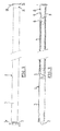
- a rollo assembly according to the invention comprises a rollo 1 and a stationary mounting assembly 2a,2b therefore.
- the stationary mounting assembly 2a,2b has been indicated schematically in dotted lines.
- the rollo 1 comprises a rotatable winding tube 3 for a rollo screen (not illustrated) and mounted for rotation in the stationary mounting assembly 2a,2b.
- a spring 4 is illustrated for loading said winding tube 3 in a direction for winding the rollo screen onto the winding tube.
- a first end of the spring 4 is connected to the winding tube 3 by means of an intermediate member 5 and a second end is connected to a mounting part 6 positioned within the winding tube and connected to part 2b of the stationary mounting assembly in a manner to be described later.
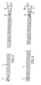
- figure 5 in which the winding tube 3 is omitted), clearly showing the (torsion) spring 4, intermediate member 5 and mounting part 6. Further figure 5 illustrates a bearing part 7 (also indicated in figures 1 and 2 ) which is attached to the winding tube 3 and with which the winding tube is borne in part 2a of the stationary mounting assembly.
- the mounting part 6 extends through and is borne by a bearing member 8 which is attached to (in the present case inserted into) the winding tube 3 (e.g. clamped). It is possible for example that the bearing member 8 is compressible by the winding tube 3 when being inserted therein for locking the mounting part 6 in a rotatable state.
- the bearing member 8 may comprise flexible fingers 9 which, when compressed, engage the mounting part 6.
- said mounting part 6 comprises projecting locking elements 10,11 for cooperation with corresponding locking members (to be described later) of part 2b of the mounting assembly.
- Said locking elements 10,11 are rotatable relative to said part 2b between a first rotational position in which the mounting part 6 can be inserted in or removed from said part 2b of the mounting assembly, and a second rotational position in which the locking elements and locking members prevent any translational movement of the rollo 1 relative to the stationary mounting assembly 2a,2b, and wherein said spring 4 loads the mounting part 6 towards the second rotational position.
- the locking members of the stationary member 2b of the mounting assembly comprise a recess 12 (see figures 6 and 7 ) for receiving the locking elements 10,11 of the mounting part, with an entrance opening and an abutment member 13 positioned in said entrance opening.
- the locking elements are shaped as two spaced locking wings 10,11, which in said first rotational position ( figure 6 ) may pass at opposite sides from the abutment member 13 (in figure 6 in a vertical downward direction substantially perpendicularly to the longitudinal axis of the winding tube) for entering the recess 12.
- Wing 10 and the inner wall of said recess 12 define cooperating circle segment shaped guides 14,15 for guiding the rotation between the first and second rotational positions.
- wing 11 and the abutment member 13 define cooperating circle segment shaped guides 16 and 17.
- a locking pin 18 which is insertable through aligned apertures (not illustrated in detail) in the winding tube 3 and mounting part 6 (and the bearing member 8, if provided) is provided for temporarily rotationally locking the mounting part 6 with respect to the winding tube 3, especially during mounting the rollo into the mounting assembly 2a,2b.
- the spring 4 Upon removal of said pin 18 the spring 4 will urge the mounting part 6 with its wings 10 and 11 from the position illustrated in figure 6 towards the position illustrated in figure 7 and will keep it in said position.
- the winding tube 3 is rotated by hand to a position in which the apertures in the winding tube 3 and in the mounting part 6 are aligned, after which the locking pin is reinserted. Then the assembly of winding tube 3 and mounting part 6 with its wings 10,11 is rotated back to the position illustrated in figure 6 such that the rollo can be moved upwards while moving the wings 10,11 out of the recess 12.
Landscapes
- Engineering & Computer Science (AREA)
- Structural Engineering (AREA)
- Architecture (AREA)
- Civil Engineering (AREA)
- Mechanical Engineering (AREA)
- Operating, Guiding And Securing Of Roll- Type Closing Members (AREA)
Abstract
Description
- The invention relates to a rollo assembly, comprising a rollo and a stationary mounting assembly therefore, wherein the rollo comprises a rotatable winding tube for a rollo screen mounted for rotation in the stationary mounting assembly and a spring for loading said winding tube in a direction for winding the rollo screen onto the winding tube, of which spring a first end is connected to the winding tube and of which a second end is connected to a mounting part positioned within the winding tube and connected to the stationary mounting assembly.
- In a known type of rollo assembly (for example as applied in open roof constructions for vehicles) the mounting part comprises a stationary shaft extending centrally within the winding tube over at least part of its length. For mounting or dismounting the rollo to or from the stationary mounting assembly, the shaft has to be attached to or detached from the stationary mounting assembly, requiring dedicated attachment means and tools.
- It is an object of the present invention to provide an improved rollo assembly of the above mentioned type.
- Thus, in accordance with the present invention a rollo assembly is provided in which said mounting part comprises projecting locking elements for cooperation with corresponding locking members of the mounting assembly and for a rotation relative thereto between a first rotational position in which the mounting part can be inserted in or removed from the mounting assembly, and a second rotational position in which the locking elements and locking members prevent any translational movement of the rollo relative to the stationary mounting assembly, and wherein said spring loads the mounting part towards the second rotational position.
- As a result of this construction the spring is used for two functions. Firstly, as is common for such springs, for loading the winding tube in a direction for winding the screen thereon. And secondly for creating a locking engagement between the mounting part and stationary mounting assembly which does not need any additional means to maintain said locking state. During mounting, the mounting part (thus the locking elements thereof) initially is kept in its first rotational position and finally is released to move to the second rotational position by the spring. During normal operation the spring maintains said second rotational position and prevents that the rollo can become detached from the stationary mounting assembly. When, however, the rollo has to be removed (e.g. for servicing) the locking elements of the mounting part are rotated towards the first rotational position against the spring load of the spring.
- In one embodiment of the rollo assembly according to the present invention means are provided for temporarily locking the mounting part with respect to the winding tube.
- Such means maintain the spring in a loaded position (as will be needed for a proper operation of the rollo assembly, i.e. winding the screen) even when the rollo has not yet been mounted to the stationary mounting assembly. This means, however, will be removed when the mounting part has been brought into engagement with the stationary mounting assembly and yet is in its first rotational position, after which the mounting part (the locking elements) rotate to the second rotational position under influence of the spring.
- In one embodiment, then, of the rollo assembly said means comprise a locking pin insertable through aligned apertures in the winding tube and mounting part. For example, when installing the rollo assembly, firstly the spring is loaded as needed by sufficiently rotating the mounting part relative to the winding tube. Then the apertures of the mounting part and winding tube are aligned and the locking pin is inserted. Next the mounting part is engaged with the stationary mounting assembly in its first rotational position and, after removing the locking pin, automatically rotates towards the second rotational position in which the mounting process is completed.
- The locking pin likewise may be used again when the rollo is detached from the stationary mounting assembly.
- In another embodiment of the rollo assembly according to the present invention the mounting part extends through and is borne by a bearing member which is attached to the winding tube. Such a bearing member enables a good functioning of the rollo during normal operation, i.e. a proper rotation of the mounting part with respect to the winding tube without the need for a complicated inner shape of the winding tube. It also may make the installation of the mounting part into the winding tube easier.
- As an example the bearing member may be compressible by the winding tube for locking the mounting part in a rotatable state. In a non compressed state of the bearing member the mounting part is inserted therein and next the assembly of bearing member and mounting part is inserted into the winding tube. The bearing member is compressed then and the mounting part is locked therein while remaining rotatable.
- In yet another embodiment of the rollo assembly according to the present invention, in said first rotational position of the locking elements of the mounting part said mounting part can be inserted in or removed from the stationary member of the mounting assembly in a direction substantially perpendicularly to the longitudinal axis of the winding tube.
- As a result the space needed for mounting or dismounting the rollo is minimised because no movements in the longitudinal direction of the winding tube are required.
- In a special embodiment the locking members of the stationary member of the mounting assembly comprise a recess for receiving the locking elements of the mounting part, with an entrance opening and an abutment member positioned in said entrance opening, wherein the locking elements comprise two spaced locking wings, which in said first rotational position may pass at opposite sides from the abutment member for entering or leaving the recess, and wherein in the second rotational position one of said wings cooperates with the abutment member for preventing the mounting part to leave the recess.
- For enabling a smooth transition from one rotational position in another, it is possible that at least one of said wings and the wall of said recess define cooperating circle segment shaped guides. It is also possible that at least one of said wings and the abutment member define cooperating circle segment shaped guides.
- Hereinafter the invention will be elucidated while referring to the drawings in which an embodiment of the rollo assembly according to the invention is shown and in which:
-
Figure 1 shows a side elevational view of a rollo assembly; -
Figure 2 shows a schematic longitudinal section of the rollo illustrated infigure 1 ; -
Figure 3 shows the inner parts of the rollo in a top plan view; -
Figure 4 shows the inner parts of the rollo in a side elevational view; -
Figure 5 shows the inner parts of the rollo in a perspective view; -
Figure 6 shows the cooperation between mounting part and stationary mounting assembly in a first rotational position, and -
Figure 7 shows the cooperation between mounting part and stationary mounting assembly in a second rotational position. - Firstly referring to
figures 1 and 2 , a rollo assembly according to the invention comprises a rollo 1 and astationary mounting assembly 2a,2b therefore. Thestationary mounting assembly 2a,2b has been indicated schematically in dotted lines. The rollo 1 comprises a rotatable winding tube 3 for a rollo screen (not illustrated) and mounted for rotation in thestationary mounting assembly 2a,2b. Further aspring 4 is illustrated for loading said winding tube 3 in a direction for winding the rollo screen onto the winding tube. A first end of thespring 4 is connected to the winding tube 3 by means of an intermediate member 5 and a second end is connected to amounting part 6 positioned within the winding tube and connected topart 2b of the stationary mounting assembly in a manner to be described later. - Reference is made too to
figure 5 (in which the winding tube 3 is omitted), clearly showing the (torsion)spring 4, intermediate member 5 and mountingpart 6. Furtherfigure 5 illustrates a bearing part 7 (also indicated infigures 1 and 2 ) which is attached to the winding tube 3 and with which the winding tube is borne in part 2a of the stationary mounting assembly. - As an alternative it is possible to combine
parts 5 and 7, but for purposes of tensioning the spring 4 (as is known per se) this is not preferred. - The
mounting part 6 extends through and is borne by abearing member 8 which is attached to (in the present case inserted into) the winding tube 3 (e.g. clamped). It is possible for example that the bearingmember 8 is compressible by the winding tube 3 when being inserted therein for locking themounting part 6 in a rotatable state. As an example, the bearingmember 8 may compriseflexible fingers 9 which, when compressed, engage themounting part 6. - As shown best in
figure 5 said mountingpart 6 comprises projectinglocking elements part 2b of the mounting assembly. Saidlocking elements part 2b between a first rotational position in which themounting part 6 can be inserted in or removed from saidpart 2b of the mounting assembly, and a second rotational position in which the locking elements and locking members prevent any translational movement of the rollo 1 relative to thestationary mounting assembly 2a,2b, and wherein saidspring 4 loads the mountingpart 6 towards the second rotational position. - The locking members of the
stationary member 2b of the mounting assembly comprise a recess 12 (seefigures 6 and 7 ) for receiving thelocking elements abutment member 13 positioned in said entrance opening. The locking elements are shaped as two spacedlocking wings figure 6 ) may pass at opposite sides from the abutment member 13 (infigure 6 in a vertical downward direction substantially perpendicularly to the longitudinal axis of the winding tube) for entering therecess 12. Upon rotation of said wings (infigure 6 anti clockwise) the second rotational position is reached (as illustrated infigure 7 ) in whichwing 11 cooperates with theabutment member 13 for preventing themounting part 6 to leave therecess 12 in the opposite direction. -
Wing 10 and the inner wall of saidrecess 12 define cooperating circle segment shaped guides 14,15 for guiding the rotation between the first and second rotational positions. - Likewise
wing 11 and theabutment member 13 define cooperating circle segmentshaped guides 16 and 17. - A
locking pin 18 which is insertable through aligned apertures (not illustrated in detail) in the winding tube 3 and mounting part 6 (and thebearing member 8, if provided) is provided for temporarily rotationally locking themounting part 6 with respect to the winding tube 3, especially during mounting the rollo into themounting assembly 2a,2b. Upon removal of saidpin 18 thespring 4 will urge themounting part 6 with itswings figure 6 towards the position illustrated infigure 7 and will keep it in said position. - For again removing the rollo 1, the winding tube 3 is rotated by hand to a position in which the apertures in the winding tube 3 and in the
mounting part 6 are aligned, after which the locking pin is reinserted. Then the assembly of winding tube 3 and mountingpart 6 with itswings figure 6 such that the rollo can be moved upwards while moving thewings recess 12. - The invention is not limited to the embodiments described before which may be varied widely within the scope of the invention as defined by the appending claims.
Claims (9)
- Rollo assembly, comprising a rollo and a stationary mounting assembly therefore, wherein the rollo comprises a rotatable winding tube for a rollo screen mounted for rotation in the stationary mounting assembly and a spring for loading said winding tube in a direction for winding the rollo screen onto the winding tube, of which spring a first end is connected to the winding tube and of which a second end is connected to a mounting part positioned within the winding tube and connected to the stationary mounting assembly, characterized in that said mounting part comprises projecting locking elements for cooperation with corresponding locking members of the mounting assembly and for a rotation relative thereto between a first rotational position in which the mounting part can be inserted in or removed from the mounting assembly, and a second rotational position in which the locking elements and locking members prevent any translational movement of the rollo relative to the stationary mounting assembly, and wherein said spring loads the mounting part towards the second rotational position.
- Rollo assembly according to claim 1, wherein means are provided for temporarily locking the mounting part with respect to the winding tube.
- Rollo assembly according to claim 2, wherein said means comprise a locking pin insertable through aligned apertures in the winding tube and mounting part.
- Rollo assembly according to any of the previous claims, wherein the mounting part extends through and is borne by a bearing member which is attached to the winding tube.
- Rollo assembly according to claim 4, wherein the bearing member is compressible by the winding tube for locking the mounting part in a rotatable state.
- Rollo assembly according to any of the previous claims, wherein in said first rotational position of the locking elements of the mounting part said mounting part can be inserted in or removed from the stationary member of the mounting assembly in a direction substantially perpendicularly to the longitudinal axis of the winding tube.
- Rollo assembly according to claim 6, wherein the locking members of the stationary member of the mounting assembly comprise a recess for receiving the locking elements of the mounting part, with an entrance opening and an abutment member positioned in said entrance opening, wherein the locking elements comprise two spaced locking wings, which in said first rotational position may pass at opposite sides from the abutment member for entering or leaving the recess, and wherein in the second rotational position one of said wings cooperates with the abutment member for preventing the mounting part to leave the recess.
- Rollo assembly according to claim 7, wherein at least one of said wings and the wall of said recess define cooperating circle segment shaped guides.
- Rollo assembly according to claim 7 or 8, wherein at least one of said wings and the abutment member define cooperating circle segment shaped guides.
Priority Applications (3)
| Application Number | Priority Date | Filing Date | Title |
|---|---|---|---|
| EP20100174821 EP2426308B1 (en) | 2010-09-01 | 2010-09-01 | Rollo assembly |
| US13/220,031 US8973644B2 (en) | 2010-09-01 | 2011-08-29 | Rollable screen assembly |
| CN201110251782.2A CN102434074B (en) | 2010-09-01 | 2011-08-30 | Winding assembly |
Applications Claiming Priority (1)
| Application Number | Priority Date | Filing Date | Title |
|---|---|---|---|
| EP20100174821 EP2426308B1 (en) | 2010-09-01 | 2010-09-01 | Rollo assembly |
Publications (2)
| Publication Number | Publication Date |
|---|---|
| EP2426308A1 true EP2426308A1 (en) | 2012-03-07 |
| EP2426308B1 EP2426308B1 (en) | 2013-04-17 |
Family
ID=43033072
Family Applications (1)
| Application Number | Title | Priority Date | Filing Date |
|---|---|---|---|
| EP20100174821 Active EP2426308B1 (en) | 2010-09-01 | 2010-09-01 | Rollo assembly |
Country Status (3)
| Country | Link |
|---|---|
| US (1) | US8973644B2 (en) |
| EP (1) | EP2426308B1 (en) |
| CN (1) | CN102434074B (en) |
Cited By (1)
| Publication number | Priority date | Publication date | Assignee | Title |
|---|---|---|---|---|
| ES2757978A1 (en) * | 2018-10-30 | 2020-04-30 | Viuda De Rafael Estevan Gimenez S L | LOCKING AND UNLOCKING DEVICE FOR A ROLLING MECHANISM FOR A MOSQUITO NET AND ROLLING BLIND DRAWER INCLUDING SUCH DEVICE |
Families Citing this family (12)
| Publication number | Priority date | Publication date | Assignee | Title |
|---|---|---|---|---|
| JP6053139B2 (en) * | 2013-01-28 | 2016-12-27 | 林テレンプ株式会社 | Shielding device |
| JP6081319B2 (en) * | 2013-08-26 | 2017-02-15 | 林テレンプ株式会社 | Shielding device and assembly method thereof |
| US9631425B2 (en) * | 2015-09-08 | 2017-04-25 | Crestron Electronics, Inc. | Roller shade with a pretensioned spring and method for pretensioning the spring |
| NL2015678B1 (en) * | 2015-10-29 | 2017-05-29 | Coulisse Bv | Roller blind system comprising a releasably mountable spring operated roller blind. |
| US20170356242A1 (en) * | 2016-06-14 | 2017-12-14 | Ke-Min Lin | Blind assembly and a winding device thereof |
| DE102016125284B4 (en) * | 2016-12-21 | 2018-07-05 | Webasto SE | Vehicle roof with carrier section and roller blind arrangement |
| US20180305980A1 (en) * | 2017-04-24 | 2018-10-25 | David R. Hall | Spring-Tensioned Roll-Up Wall |
| DE102017110747B4 (en) * | 2017-05-17 | 2024-07-11 | Roof Systems Germany Gmbh | Spring cassette for a roof blind system of a motor vehicle and assembly for a roof blind system of a motor vehicle |
| DE102017110746A1 (en) * | 2017-05-17 | 2018-11-22 | Roof Systems Germany Gmbh | Roof roller blind system for a motor vehicle and method for mounting a roof roller blind system for a motor vehicle |
| US10738530B2 (en) | 2018-01-16 | 2020-08-11 | Crestron Electronics, Inc. | Motor pretensioned roller shade |
| JP7056169B2 (en) * | 2018-01-24 | 2022-04-19 | 株式会社アイシン | Manufacturing method of roll shade equipment and roll shade equipment |
| US12434083B2 (en) * | 2021-11-02 | 2025-10-07 | Smoke Guard, Inc. | Deployable fire or smoke barrier with manual egress |
Citations (4)
| Publication number | Priority date | Publication date | Assignee | Title |
|---|---|---|---|---|
| DE19531954A1 (en) * | 1994-10-10 | 1996-04-11 | Aerolux Produktion & Handel | Support for flattened shaft end of roller blind |
| US6039107A (en) * | 1999-02-12 | 2000-03-21 | Pittard; Michael L. | Vehicle window shade assembly |
| US6457688B1 (en) * | 1998-12-03 | 2002-10-01 | Hunter Douglas Industries B.V. | End cap and mounting support combination |
| EP1703071A1 (en) * | 2005-02-15 | 2006-09-20 | Hamstra B.V. | Winding mechanism for a roller screen and mounting means |
Family Cites Families (14)
| Publication number | Priority date | Publication date | Assignee | Title |
|---|---|---|---|---|
| US1212969A (en) * | 1916-06-23 | 1917-01-16 | Landers Frary & Clark | Process of making table-knives and product thereof. |
| US1600374A (en) * | 1926-03-01 | 1926-09-21 | William P Talbot | Shade bracket |
| JPS53152814U (en) * | 1977-05-07 | 1978-12-01 | ||
| US5464052A (en) * | 1993-11-08 | 1995-11-07 | Takata, Inc. | Security shade with a motor spring subassembly |
| FR2736086A1 (en) * | 1995-06-28 | 1997-01-03 | Bubendorff Sa | Motorised roller shutter |
| NL1009743C2 (en) | 1998-07-27 | 2000-01-28 | Inalfa Ind Bv | Open roof construction for a vehicle, as well as a vehicle equipped with such an open roof construction. |
| DE102004024682A1 (en) | 2004-05-19 | 2005-12-15 | Bos Gmbh & Co. Kg | Roller blind with spiral spring drive |
| US7201417B2 (en) * | 2005-06-16 | 2007-04-10 | Nissan Technical Center North America, Inc. | Covering mechanism |
| US7549457B2 (en) * | 2005-08-22 | 2009-06-23 | Irvin Automotive Products, Inc. | Silicone shade |
| DE102005049989B4 (en) * | 2005-10-14 | 2007-07-12 | Bos Gmbh & Co. Kg | Protective device with exchangeable adapter parts |
| DE102005062973A1 (en) * | 2005-12-28 | 2007-07-12 | Bos Gmbh & Co. Kg | Roller blind with simplified assembly of the winding shaft |
| DE102006047123B3 (en) * | 2006-09-26 | 2008-04-24 | Bos Gmbh & Co. Kg | The blind assembly |
| ATE447474T1 (en) * | 2006-11-23 | 2009-11-15 | Coperion Gmbh | PLANT FOR PROCESSING MATERIALS |
| JP4355741B2 (en) * | 2007-10-24 | 2009-11-04 | 株式会社鹿田産業 | Roll screen device |
-
2010
- 2010-09-01 EP EP20100174821 patent/EP2426308B1/en active Active
-
2011
- 2011-08-29 US US13/220,031 patent/US8973644B2/en active Active
- 2011-08-30 CN CN201110251782.2A patent/CN102434074B/en active Active
Patent Citations (4)
| Publication number | Priority date | Publication date | Assignee | Title |
|---|---|---|---|---|
| DE19531954A1 (en) * | 1994-10-10 | 1996-04-11 | Aerolux Produktion & Handel | Support for flattened shaft end of roller blind |
| US6457688B1 (en) * | 1998-12-03 | 2002-10-01 | Hunter Douglas Industries B.V. | End cap and mounting support combination |
| US6039107A (en) * | 1999-02-12 | 2000-03-21 | Pittard; Michael L. | Vehicle window shade assembly |
| EP1703071A1 (en) * | 2005-02-15 | 2006-09-20 | Hamstra B.V. | Winding mechanism for a roller screen and mounting means |
Cited By (1)
| Publication number | Priority date | Publication date | Assignee | Title |
|---|---|---|---|---|
| ES2757978A1 (en) * | 2018-10-30 | 2020-04-30 | Viuda De Rafael Estevan Gimenez S L | LOCKING AND UNLOCKING DEVICE FOR A ROLLING MECHANISM FOR A MOSQUITO NET AND ROLLING BLIND DRAWER INCLUDING SUCH DEVICE |
Also Published As
| Publication number | Publication date |
|---|---|
| CN102434074A (en) | 2012-05-02 |
| CN102434074B (en) | 2016-04-20 |
| EP2426308B1 (en) | 2013-04-17 |
| US8973644B2 (en) | 2015-03-10 |
| US20120048484A1 (en) | 2012-03-01 |
Similar Documents
| Publication | Publication Date | Title |
|---|---|---|
| EP2426308B1 (en) | Rollo assembly | |
| CN104011423B (en) | spring limit clip | |
| JP5079679B2 (en) | Connection assembly for fastening the additional element onto the carrier element | |
| EP2152996B1 (en) | Window regulator assembly for a vehicle | |
| US8651815B2 (en) | Lightweight stow abort mechanism | |
| US7976078B2 (en) | Device and method for the detachable connection of structural parts, in particular in an aircraft | |
| US20140099156A1 (en) | Bearing Arrangement Having A Bearing Socket | |
| EP2065545A2 (en) | Hood stay apparatus for engine room in heavy construction equipment | |
| CN105083524B (en) | Fastener device for fastening panel to structure, and aircraft | |
| CN206317661U (en) | Shutter arrangement | |
| US9616735B2 (en) | Vehicle roll shade device | |
| CN105317988A (en) | Shift Knob Structure | |
| KR20210046908A (en) | Hold open lock apparatus of sliding door | |
| CN102926645B (en) | Sheet material roller shutter door | |
| CN103270235B (en) | Window regulator assembly | |
| US20120066870A1 (en) | Quick-fit anchoring device for anchoring a sheath of a control cable to a mounting bracket | |
| EP2743431B1 (en) | Latch device | |
| US10876328B2 (en) | Door handle assembly for a motor vehicle | |
| EP3372773B1 (en) | Roller screen | |
| CN107521316B (en) | Roller shutter assembly | |
| EP2095982A1 (en) | Window regulator and jig | |
| EP2286053B1 (en) | Safety device for screens on tube, particularly for technical curtains, mosquito nets, nets and roller screens | |
| US20210245589A1 (en) | Assembly for a cover of a vehicle roof, and vehicle roof for a motor vehicle | |
| CN107517062A (en) | A kind of Kato component | |
| US7849634B2 (en) | Vehicle window regulator device, method of installation of a vehicle window regulator device, and a vehicle window regulator locking device |
Legal Events
| Date | Code | Title | Description |
|---|---|---|---|
| AK | Designated contracting states |
Kind code of ref document: A1 Designated state(s): AL AT BE BG CH CY CZ DE DK EE ES FI FR GB GR HR HU IE IS IT LI LT LU LV MC MK MT NL NO PL PT RO SE SI SK SM TR |
|
| AX | Request for extension of the european patent |
Extension state: BA ME RS |
|
| PUAI | Public reference made under article 153(3) epc to a published international application that has entered the european phase |
Free format text: ORIGINAL CODE: 0009012 |
|
| 17P | Request for examination filed |
Effective date: 20120903 |
|
| GRAP | Despatch of communication of intention to grant a patent |
Free format text: ORIGINAL CODE: EPIDOSNIGR1 |
|
| RIC1 | Information provided on ipc code assigned before grant |
Ipc: B60J 7/00 20060101ALI20121024BHEP Ipc: E06B 9/42 20060101AFI20121024BHEP Ipc: E06B 9/50 20060101ALI20121024BHEP Ipc: B60J 1/20 20060101ALI20121024BHEP |
|
| GRAS | Grant fee paid |
Free format text: ORIGINAL CODE: EPIDOSNIGR3 |
|
| GRAA | (expected) grant |
Free format text: ORIGINAL CODE: 0009210 |
|
| AK | Designated contracting states |
Kind code of ref document: B1 Designated state(s): AL AT BE BG CH CY CZ DE DK EE ES FI FR GB GR HR HU IE IS IT LI LT LU LV MC MK MT NL NO PL PT RO SE SI SK SM TR |
|
| REG | Reference to a national code |
Ref country code: GB Ref legal event code: FG4D |
|
| REG | Reference to a national code |
Ref country code: CH Ref legal event code: EP |
|
| REG | Reference to a national code |
Ref country code: IE Ref legal event code: FG4D |
|
| REG | Reference to a national code |
Ref country code: AT Ref legal event code: REF Ref document number: 607424 Country of ref document: AT Kind code of ref document: T Effective date: 20130515 |
|
| REG | Reference to a national code |
Ref country code: DE Ref legal event code: R096 Ref document number: 602010006203 Country of ref document: DE Effective date: 20130613 |
|
| REG | Reference to a national code |
Ref country code: AT Ref legal event code: MK05 Ref document number: 607424 Country of ref document: AT Kind code of ref document: T Effective date: 20130417 |
|
| REG | Reference to a national code |
Ref country code: LT Ref legal event code: MG4D |
|
| REG | Reference to a national code |
Ref country code: NL Ref legal event code: VDEP Effective date: 20130417 |
|
| PG25 | Lapsed in a contracting state [announced via postgrant information from national office to epo] |
Ref country code: FI Free format text: LAPSE BECAUSE OF FAILURE TO SUBMIT A TRANSLATION OF THE DESCRIPTION OR TO PAY THE FEE WITHIN THE PRESCRIBED TIME-LIMIT Effective date: 20130417 Ref country code: AT Free format text: LAPSE BECAUSE OF FAILURE TO SUBMIT A TRANSLATION OF THE DESCRIPTION OR TO PAY THE FEE WITHIN THE PRESCRIBED TIME-LIMIT Effective date: 20130417 Ref country code: ES Free format text: LAPSE BECAUSE OF FAILURE TO SUBMIT A TRANSLATION OF THE DESCRIPTION OR TO PAY THE FEE WITHIN THE PRESCRIBED TIME-LIMIT Effective date: 20130728 Ref country code: NO Free format text: LAPSE BECAUSE OF FAILURE TO SUBMIT A TRANSLATION OF THE DESCRIPTION OR TO PAY THE FEE WITHIN THE PRESCRIBED TIME-LIMIT Effective date: 20130717 Ref country code: PT Free format text: LAPSE BECAUSE OF FAILURE TO SUBMIT A TRANSLATION OF THE DESCRIPTION OR TO PAY THE FEE WITHIN THE PRESCRIBED TIME-LIMIT Effective date: 20130819 Ref country code: LT Free format text: LAPSE BECAUSE OF FAILURE TO SUBMIT A TRANSLATION OF THE DESCRIPTION OR TO PAY THE FEE WITHIN THE PRESCRIBED TIME-LIMIT Effective date: 20130417 Ref country code: IS Free format text: LAPSE BECAUSE OF FAILURE TO SUBMIT A TRANSLATION OF THE DESCRIPTION OR TO PAY THE FEE WITHIN THE PRESCRIBED TIME-LIMIT Effective date: 20130817 Ref country code: SI Free format text: LAPSE BECAUSE OF FAILURE TO SUBMIT A TRANSLATION OF THE DESCRIPTION OR TO PAY THE FEE WITHIN THE PRESCRIBED TIME-LIMIT Effective date: 20130417 Ref country code: SE Free format text: LAPSE BECAUSE OF FAILURE TO SUBMIT A TRANSLATION OF THE DESCRIPTION OR TO PAY THE FEE WITHIN THE PRESCRIBED TIME-LIMIT Effective date: 20130417 Ref country code: BE Free format text: LAPSE BECAUSE OF FAILURE TO SUBMIT A TRANSLATION OF THE DESCRIPTION OR TO PAY THE FEE WITHIN THE PRESCRIBED TIME-LIMIT Effective date: 20130417 Ref country code: GR Free format text: LAPSE BECAUSE OF FAILURE TO SUBMIT A TRANSLATION OF THE DESCRIPTION OR TO PAY THE FEE WITHIN THE PRESCRIBED TIME-LIMIT Effective date: 20130718 |
|
| PG25 | Lapsed in a contracting state [announced via postgrant information from national office to epo] |
Ref country code: CY Free format text: LAPSE BECAUSE OF FAILURE TO SUBMIT A TRANSLATION OF THE DESCRIPTION OR TO PAY THE FEE WITHIN THE PRESCRIBED TIME-LIMIT Effective date: 20130417 Ref country code: BG Free format text: LAPSE BECAUSE OF FAILURE TO SUBMIT A TRANSLATION OF THE DESCRIPTION OR TO PAY THE FEE WITHIN THE PRESCRIBED TIME-LIMIT Effective date: 20130717 Ref country code: PL Free format text: LAPSE BECAUSE OF FAILURE TO SUBMIT A TRANSLATION OF THE DESCRIPTION OR TO PAY THE FEE WITHIN THE PRESCRIBED TIME-LIMIT Effective date: 20130417 Ref country code: LV Free format text: LAPSE BECAUSE OF FAILURE TO SUBMIT A TRANSLATION OF THE DESCRIPTION OR TO PAY THE FEE WITHIN THE PRESCRIBED TIME-LIMIT Effective date: 20130417 Ref country code: HR Free format text: LAPSE BECAUSE OF FAILURE TO SUBMIT A TRANSLATION OF THE DESCRIPTION OR TO PAY THE FEE WITHIN THE PRESCRIBED TIME-LIMIT Effective date: 20130417 |
|
| PG25 | Lapsed in a contracting state [announced via postgrant information from national office to epo] |
Ref country code: DK Free format text: LAPSE BECAUSE OF FAILURE TO SUBMIT A TRANSLATION OF THE DESCRIPTION OR TO PAY THE FEE WITHIN THE PRESCRIBED TIME-LIMIT Effective date: 20130417 Ref country code: CZ Free format text: LAPSE BECAUSE OF FAILURE TO SUBMIT A TRANSLATION OF THE DESCRIPTION OR TO PAY THE FEE WITHIN THE PRESCRIBED TIME-LIMIT Effective date: 20130417 Ref country code: EE Free format text: LAPSE BECAUSE OF FAILURE TO SUBMIT A TRANSLATION OF THE DESCRIPTION OR TO PAY THE FEE WITHIN THE PRESCRIBED TIME-LIMIT Effective date: 20130417 Ref country code: SK Free format text: LAPSE BECAUSE OF FAILURE TO SUBMIT A TRANSLATION OF THE DESCRIPTION OR TO PAY THE FEE WITHIN THE PRESCRIBED TIME-LIMIT Effective date: 20130417 |
|
| PLBE | No opposition filed within time limit |
Free format text: ORIGINAL CODE: 0009261 |
|
| STAA | Information on the status of an ep patent application or granted ep patent |
Free format text: STATUS: NO OPPOSITION FILED WITHIN TIME LIMIT |
|
| PG25 | Lapsed in a contracting state [announced via postgrant information from national office to epo] |
Ref country code: IT Free format text: LAPSE BECAUSE OF FAILURE TO SUBMIT A TRANSLATION OF THE DESCRIPTION OR TO PAY THE FEE WITHIN THE PRESCRIBED TIME-LIMIT Effective date: 20130417 Ref country code: NL Free format text: LAPSE BECAUSE OF FAILURE TO SUBMIT A TRANSLATION OF THE DESCRIPTION OR TO PAY THE FEE WITHIN THE PRESCRIBED TIME-LIMIT Effective date: 20130417 Ref country code: RO Free format text: LAPSE BECAUSE OF FAILURE TO SUBMIT A TRANSLATION OF THE DESCRIPTION OR TO PAY THE FEE WITHIN THE PRESCRIBED TIME-LIMIT Effective date: 20130417 |
|
| 26N | No opposition filed |
Effective date: 20140120 |
|
| PG25 | Lapsed in a contracting state [announced via postgrant information from national office to epo] |
Ref country code: MC Free format text: LAPSE BECAUSE OF FAILURE TO SUBMIT A TRANSLATION OF THE DESCRIPTION OR TO PAY THE FEE WITHIN THE PRESCRIBED TIME-LIMIT Effective date: 20130417 |
|
| REG | Reference to a national code |
Ref country code: DE Ref legal event code: R097 Ref document number: 602010006203 Country of ref document: DE Effective date: 20140120 |
|
| REG | Reference to a national code |
Ref country code: IE Ref legal event code: MM4A |
|
| PG25 | Lapsed in a contracting state [announced via postgrant information from national office to epo] |
Ref country code: IE Free format text: LAPSE BECAUSE OF NON-PAYMENT OF DUE FEES Effective date: 20130901 |
|
| REG | Reference to a national code |
Ref country code: CH Ref legal event code: PL |
|
| PG25 | Lapsed in a contracting state [announced via postgrant information from national office to epo] |
Ref country code: SM Free format text: LAPSE BECAUSE OF FAILURE TO SUBMIT A TRANSLATION OF THE DESCRIPTION OR TO PAY THE FEE WITHIN THE PRESCRIBED TIME-LIMIT Effective date: 20130417 |
|
| PG25 | Lapsed in a contracting state [announced via postgrant information from national office to epo] |
Ref country code: MT Free format text: LAPSE BECAUSE OF FAILURE TO SUBMIT A TRANSLATION OF THE DESCRIPTION OR TO PAY THE FEE WITHIN THE PRESCRIBED TIME-LIMIT Effective date: 20130417 Ref country code: TR Free format text: LAPSE BECAUSE OF FAILURE TO SUBMIT A TRANSLATION OF THE DESCRIPTION OR TO PAY THE FEE WITHIN THE PRESCRIBED TIME-LIMIT Effective date: 20130417 |
|
| PG25 | Lapsed in a contracting state [announced via postgrant information from national office to epo] |
Ref country code: LI Free format text: LAPSE BECAUSE OF NON-PAYMENT OF DUE FEES Effective date: 20140930 Ref country code: LU Free format text: LAPSE BECAUSE OF NON-PAYMENT OF DUE FEES Effective date: 20130901 Ref country code: MK Free format text: LAPSE BECAUSE OF FAILURE TO SUBMIT A TRANSLATION OF THE DESCRIPTION OR TO PAY THE FEE WITHIN THE PRESCRIBED TIME-LIMIT Effective date: 20130417 Ref country code: HU Free format text: LAPSE BECAUSE OF FAILURE TO SUBMIT A TRANSLATION OF THE DESCRIPTION OR TO PAY THE FEE WITHIN THE PRESCRIBED TIME-LIMIT; INVALID AB INITIO Effective date: 20100901 Ref country code: CH Free format text: LAPSE BECAUSE OF NON-PAYMENT OF DUE FEES Effective date: 20140930 |
|
| REG | Reference to a national code |
Ref country code: FR Ref legal event code: PLFP Year of fee payment: 7 |
|
| PGFP | Annual fee paid to national office [announced via postgrant information from national office to epo] |
Ref country code: GB Payment date: 20160927 Year of fee payment: 7 |
|
| REG | Reference to a national code |
Ref country code: FR Ref legal event code: PLFP Year of fee payment: 8 |
|
| GBPC | Gb: european patent ceased through non-payment of renewal fee |
Effective date: 20170901 |
|
| PG25 | Lapsed in a contracting state [announced via postgrant information from national office to epo] |
Ref country code: GB Free format text: LAPSE BECAUSE OF NON-PAYMENT OF DUE FEES Effective date: 20170901 |
|
| REG | Reference to a national code |
Ref country code: FR Ref legal event code: PLFP Year of fee payment: 9 |
|
| PG25 | Lapsed in a contracting state [announced via postgrant information from national office to epo] |
Ref country code: AL Free format text: LAPSE BECAUSE OF FAILURE TO SUBMIT A TRANSLATION OF THE DESCRIPTION OR TO PAY THE FEE WITHIN THE PRESCRIBED TIME-LIMIT Effective date: 20130417 |
|
| PGFP | Annual fee paid to national office [announced via postgrant information from national office to epo] |
Ref country code: DE Payment date: 20250929 Year of fee payment: 16 |
|
| PGFP | Annual fee paid to national office [announced via postgrant information from national office to epo] |
Ref country code: FR Payment date: 20250925 Year of fee payment: 16 |