EP2426274A2 - Modular system for connecting attachments to a construction machine - Google Patents
Modular system for connecting attachments to a construction machine Download PDFInfo
- Publication number
- EP2426274A2 EP2426274A2 EP11190011A EP11190011A EP2426274A2 EP 2426274 A2 EP2426274 A2 EP 2426274A2 EP 11190011 A EP11190011 A EP 11190011A EP 11190011 A EP11190011 A EP 11190011A EP 2426274 A2 EP2426274 A2 EP 2426274A2
- Authority
- EP
- European Patent Office
- Prior art keywords
- module
- coupling arrangement
- plate
- wing
- holes
- Prior art date
- Legal status (The legal status is an assumption and is not a legal conclusion. Google has not performed a legal analysis and makes no representation as to the accuracy of the status listed.)
- Withdrawn
Links
Images


Classifications
-
- E—FIXED CONSTRUCTIONS
- E02—HYDRAULIC ENGINEERING; FOUNDATIONS; SOIL SHIFTING
- E02F—DREDGING; SOIL-SHIFTING
- E02F3/00—Dredgers; Soil-shifting machines
- E02F3/04—Dredgers; Soil-shifting machines mechanically-driven
- E02F3/28—Dredgers; Soil-shifting machines mechanically-driven with digging tools mounted on a dipper- or bucket-arm, i.e. there is either one arm or a pair of arms, e.g. dippers, buckets
- E02F3/36—Component parts
- E02F3/3604—Devices to connect tools to arms, booms or the like
- E02F3/3609—Devices to connect tools to arms, booms or the like of the quick acting type, e.g. controlled from the operator seat
- E02F3/3618—Devices to connect tools to arms, booms or the like of the quick acting type, e.g. controlled from the operator seat with two separating hooks
-
- E—FIXED CONSTRUCTIONS
- E02—HYDRAULIC ENGINEERING; FOUNDATIONS; SOIL SHIFTING
- E02F—DREDGING; SOIL-SHIFTING
- E02F3/00—Dredgers; Soil-shifting machines
- E02F3/04—Dredgers; Soil-shifting machines mechanically-driven
- E02F3/28—Dredgers; Soil-shifting machines mechanically-driven with digging tools mounted on a dipper- or bucket-arm, i.e. there is either one arm or a pair of arms, e.g. dippers, buckets
- E02F3/30—Dredgers; Soil-shifting machines mechanically-driven with digging tools mounted on a dipper- or bucket-arm, i.e. there is either one arm or a pair of arms, e.g. dippers, buckets with a dipper-arm pivoted on a cantilever beam, i.e. boom
- E02F3/302—Dredgers; Soil-shifting machines mechanically-driven with digging tools mounted on a dipper- or bucket-arm, i.e. there is either one arm or a pair of arms, e.g. dippers, buckets with a dipper-arm pivoted on a cantilever beam, i.e. boom with an additional link
-
- E—FIXED CONSTRUCTIONS
- E02—HYDRAULIC ENGINEERING; FOUNDATIONS; SOIL SHIFTING
- E02F—DREDGING; SOIL-SHIFTING
- E02F3/00—Dredgers; Soil-shifting machines
- E02F3/04—Dredgers; Soil-shifting machines mechanically-driven
- E02F3/28—Dredgers; Soil-shifting machines mechanically-driven with digging tools mounted on a dipper- or bucket-arm, i.e. there is either one arm or a pair of arms, e.g. dippers, buckets
- E02F3/30—Dredgers; Soil-shifting machines mechanically-driven with digging tools mounted on a dipper- or bucket-arm, i.e. there is either one arm or a pair of arms, e.g. dippers, buckets with a dipper-arm pivoted on a cantilever beam, i.e. boom
- E02F3/306—Dredgers; Soil-shifting machines mechanically-driven with digging tools mounted on a dipper- or bucket-arm, i.e. there is either one arm or a pair of arms, e.g. dippers, buckets with a dipper-arm pivoted on a cantilever beam, i.e. boom with telescopic dipper-arm or boom
-
- E—FIXED CONSTRUCTIONS
- E02—HYDRAULIC ENGINEERING; FOUNDATIONS; SOIL SHIFTING
- E02F—DREDGING; SOIL-SHIFTING
- E02F3/00—Dredgers; Soil-shifting machines
- E02F3/04—Dredgers; Soil-shifting machines mechanically-driven
- E02F3/28—Dredgers; Soil-shifting machines mechanically-driven with digging tools mounted on a dipper- or bucket-arm, i.e. there is either one arm or a pair of arms, e.g. dippers, buckets
- E02F3/36—Component parts
- E02F3/3604—Devices to connect tools to arms, booms or the like
- E02F3/3609—Devices to connect tools to arms, booms or the like of the quick acting type, e.g. controlled from the operator seat
- E02F3/3622—Devices to connect tools to arms, booms or the like of the quick acting type, e.g. controlled from the operator seat with a hook and a locking element acting on a pin
-
- E—FIXED CONSTRUCTIONS
- E02—HYDRAULIC ENGINEERING; FOUNDATIONS; SOIL SHIFTING
- E02F—DREDGING; SOIL-SHIFTING
- E02F3/00—Dredgers; Soil-shifting machines
- E02F3/04—Dredgers; Soil-shifting machines mechanically-driven
- E02F3/28—Dredgers; Soil-shifting machines mechanically-driven with digging tools mounted on a dipper- or bucket-arm, i.e. there is either one arm or a pair of arms, e.g. dippers, buckets
- E02F3/36—Component parts
- E02F3/3604—Devices to connect tools to arms, booms or the like
- E02F3/3609—Devices to connect tools to arms, booms or the like of the quick acting type, e.g. controlled from the operator seat
- E02F3/3631—Devices to connect tools to arms, booms or the like of the quick acting type, e.g. controlled from the operator seat with a hook and a transversal locking element
-
- E—FIXED CONSTRUCTIONS
- E02—HYDRAULIC ENGINEERING; FOUNDATIONS; SOIL SHIFTING
- E02F—DREDGING; SOIL-SHIFTING
- E02F3/00—Dredgers; Soil-shifting machines
- E02F3/04—Dredgers; Soil-shifting machines mechanically-driven
- E02F3/28—Dredgers; Soil-shifting machines mechanically-driven with digging tools mounted on a dipper- or bucket-arm, i.e. there is either one arm or a pair of arms, e.g. dippers, buckets
- E02F3/36—Component parts
- E02F3/3604—Devices to connect tools to arms, booms or the like
- E02F3/3609—Devices to connect tools to arms, booms or the like of the quick acting type, e.g. controlled from the operator seat
- E02F3/3636—Devices to connect tools to arms, booms or the like of the quick acting type, e.g. controlled from the operator seat using two or four movable transversal pins
-
- E—FIXED CONSTRUCTIONS
- E02—HYDRAULIC ENGINEERING; FOUNDATIONS; SOIL SHIFTING
- E02F—DREDGING; SOIL-SHIFTING
- E02F3/00—Dredgers; Soil-shifting machines
- E02F3/04—Dredgers; Soil-shifting machines mechanically-driven
- E02F3/28—Dredgers; Soil-shifting machines mechanically-driven with digging tools mounted on a dipper- or bucket-arm, i.e. there is either one arm or a pair of arms, e.g. dippers, buckets
- E02F3/36—Component parts
- E02F3/3604—Devices to connect tools to arms, booms or the like
- E02F3/3686—Devices to connect tools to arms, booms or the like using adapters, i.e. additional element to mount between the coupler and the tool
-
- E—FIXED CONSTRUCTIONS
- E02—HYDRAULIC ENGINEERING; FOUNDATIONS; SOIL SHIFTING
- E02F—DREDGING; SOIL-SHIFTING
- E02F3/00—Dredgers; Soil-shifting machines
- E02F3/04—Dredgers; Soil-shifting machines mechanically-driven
- E02F3/28—Dredgers; Soil-shifting machines mechanically-driven with digging tools mounted on a dipper- or bucket-arm, i.e. there is either one arm or a pair of arms, e.g. dippers, buckets
- E02F3/36—Component parts
- E02F3/369—Devices to connect parts of a boom or an arm
-
- E—FIXED CONSTRUCTIONS
- E02—HYDRAULIC ENGINEERING; FOUNDATIONS; SOIL SHIFTING
- E02F—DREDGING; SOIL-SHIFTING
- E02F3/00—Dredgers; Soil-shifting machines
- E02F3/04—Dredgers; Soil-shifting machines mechanically-driven
- E02F3/28—Dredgers; Soil-shifting machines mechanically-driven with digging tools mounted on a dipper- or bucket-arm, i.e. there is either one arm or a pair of arms, e.g. dippers, buckets
- E02F3/36—Component parts
- E02F3/42—Drives for dippers, buckets, dipper-arms or bucket-arms
- E02F3/425—Drive systems for dipper-arms, backhoes or the like
-
- E—FIXED CONSTRUCTIONS
- E02—HYDRAULIC ENGINEERING; FOUNDATIONS; SOIL SHIFTING
- E02F—DREDGING; SOIL-SHIFTING
- E02F3/00—Dredgers; Soil-shifting machines
- E02F3/04—Dredgers; Soil-shifting machines mechanically-driven
- E02F3/96—Dredgers; Soil-shifting machines mechanically-driven with arrangements for alternate or simultaneous use of different digging elements
- E02F3/965—Dredgers; Soil-shifting machines mechanically-driven with arrangements for alternate or simultaneous use of different digging elements of metal-cutting or concrete-crushing implements
-
- E—FIXED CONSTRUCTIONS
- E02—HYDRAULIC ENGINEERING; FOUNDATIONS; SOIL SHIFTING
- E02F—DREDGING; SOIL-SHIFTING
- E02F3/00—Dredgers; Soil-shifting machines
- E02F3/04—Dredgers; Soil-shifting machines mechanically-driven
- E02F3/96—Dredgers; Soil-shifting machines mechanically-driven with arrangements for alternate or simultaneous use of different digging elements
- E02F3/966—Dredgers; Soil-shifting machines mechanically-driven with arrangements for alternate or simultaneous use of different digging elements of hammer-type tools
-
- E—FIXED CONSTRUCTIONS
- E04—BUILDING
- E04G—SCAFFOLDING; FORMS; SHUTTERING; BUILDING IMPLEMENTS OR AIDS, OR THEIR USE; HANDLING BUILDING MATERIALS ON THE SITE; REPAIRING, BREAKING-UP OR OTHER WORK ON EXISTING BUILDINGS
- E04G23/00—Working measures on existing buildings
- E04G23/08—Wrecking of buildings
- E04G23/082—Wrecking of buildings using shears, breakers, jaws and the like
-
- Y—GENERAL TAGGING OF NEW TECHNOLOGICAL DEVELOPMENTS; GENERAL TAGGING OF CROSS-SECTIONAL TECHNOLOGIES SPANNING OVER SEVERAL SECTIONS OF THE IPC; TECHNICAL SUBJECTS COVERED BY FORMER USPC CROSS-REFERENCE ART COLLECTIONS [XRACs] AND DIGESTS
- Y10—TECHNICAL SUBJECTS COVERED BY FORMER USPC
- Y10T—TECHNICAL SUBJECTS COVERED BY FORMER US CLASSIFICATION
- Y10T29/00—Metal working
- Y10T29/49—Method of mechanical manufacture
- Y10T29/49826—Assembling or joining
- Y10T29/49895—Associating parts by use of aligning means [e.g., use of a drift pin or a "fixture"]
-
- Y—GENERAL TAGGING OF NEW TECHNOLOGICAL DEVELOPMENTS; GENERAL TAGGING OF CROSS-SECTIONAL TECHNOLOGIES SPANNING OVER SEVERAL SECTIONS OF THE IPC; TECHNICAL SUBJECTS COVERED BY FORMER USPC CROSS-REFERENCE ART COLLECTIONS [XRACs] AND DIGESTS
- Y10—TECHNICAL SUBJECTS COVERED BY FORMER USPC
- Y10T—TECHNICAL SUBJECTS COVERED BY FORMER US CLASSIFICATION
- Y10T403/00—Joints and connections
- Y10T403/22—Joints and connections with fluid pressure responsive component
-
- Y—GENERAL TAGGING OF NEW TECHNOLOGICAL DEVELOPMENTS; GENERAL TAGGING OF CROSS-SECTIONAL TECHNOLOGIES SPANNING OVER SEVERAL SECTIONS OF THE IPC; TECHNICAL SUBJECTS COVERED BY FORMER USPC CROSS-REFERENCE ART COLLECTIONS [XRACs] AND DIGESTS
- Y10—TECHNICAL SUBJECTS COVERED BY FORMER USPC
- Y10T—TECHNICAL SUBJECTS COVERED BY FORMER US CLASSIFICATION
- Y10T403/00—Joints and connections
- Y10T403/70—Interfitted members
Definitions
- the present invention relates to a modular system for construction or demolition equipment which is adapted to be attached to a backhoe for attaching multiple tools, such as a heavy-duty metal cutting shear, a plate shear, a claw, a hammer, a bucket, a grapple or a concrete crusher.
- tools such as a heavy-duty metal cutting shear, a plate shear, a claw, a hammer, a bucket, a grapple or a concrete crusher.
- Such metal shears can also be utilized for reducing automobiles, truck frames, railroad cars and the like.
- the shears must be able to move and cut the metal scrap pieces regardless of the size or shape of the individual scrap pieces and without any significant damage to the shears.
- concrete crushing devices such as a concrete pulverizer or concrete crackers are also used to reduce the structure to manageable components which can be easily handled and removed from the site.
- a grapple is often utilized where handling of debris or work pieces is a primary function of the equipment. Historically, all these pieces of equipment represent distinct tools having significant independent capital costs. Consequently, the demolition industry has tended to develop one type of tool that can have the greatest possible utility and application.
- construction equipment such as a backhoe is made up of a tractor having attached thereto a hydraulically operated boom and attached to the boom is a hydraulically operated stick.
- Each manufacturer of construction equipment provides a variety of attachments for their equipment, however, these attachments fit on only that manufacture's equipment.
- the purchasing of such attachments not only requires a dedicated commitment to a single manufacturer of construction equipment, but furthermore, puts the equipment owner at a significant disadvantage if the particular equipment manufacturer does not provide a particular attachment which may be needed by the equipment owner. It is inefficient and costly for an equipment owner to own and maintain two separate construction machines because certain attachments are made by one manufacturer and certain other attachments are made by another manufacturer.
- a design is needed that will provide the machine owner with the flexibility of a single, set of attachments that may be suitable for use with any of a variety of construction machines from different manufacturers. Furthermore, a design is needed whereby a machine owner may have the flexibility to configure the attachments in any desirable sequence thereby maximizing the efficiency of the construction machine. Finally, a design is needed whereby it is possible for the machine owner to maximize the versatility of a construction machine by utilizing a plurality of different attachments that may be attached to the construction machine.
- a modular system for connecting any one of a plurality of modules to an extension arm of a construction machine comprising:
- the subject invention is also directed to an automatically actuated coupling system for securing the modules.
- Another embodiment of the subject invention is directed to a module for connecting to the extension arm of a construction machine.
- the module has a body with a first end and a second end with a proximal coupling arrangement associated with the first end and a distal coupling arrangement associated with the second end.
- the distal coupling arrangement has a plate with a hole pattern and the proximal coupling arrangement has a mating plate with an aligned matching hole pattern.
- the mounting arrangements are complimentary such that a second module having an identical one of the distal mounting arrangement or proximal mounting arrangement may be secured thereto.
- Another embodiment of the subject invention is directed to a method for remotely locking a structural module onto the extension arm of a construction tool.
- the arm and module each have matching hole patterns adapted to receive common retention pins moved by a hydraulic cylinder.
- the method comprises the steps of:
- Another embodiment of the subject invention is directed to a method of interchangeably securing structural modules to the extension arm of a construction machine, wherein each module has a standardized coupling arrangement comprising the steps of mounting a first module to the standardized coupling arrangement of the extension arm, removing the first module from the extension arm, and mounting a second module having an identical standardized coupling arrangement to the extension arm.
- Figure 1 is a schematic of a construction machine with the stick positioned to receive an attachment
- Figure 2 is a schematic of the construction machine in Figure 1 with a stick wing mounted to the stick;
- Figure 3 is a schematic of a construction machine with the boom positioned to receive an attachment
- Figure 4 is a schematic of the construction machine in Figure 3 with a boom wing attached to the boom;
- Figures 5A and 5B are a side view and a front view of a stick wing
- Figures 6A and 6B are a side view and a top view of a boom wing
- Figure 7A is an exploded isometric view of one embodiment of the coupling arrangement in accordance with the subject invention.
- Figure 7B is an assembled isometric view of the coupling arrangement illustrated in Figure 7A ;
- Figure 8 is a side view of an alternate embodiment of the coupling arrangement in accordance with the subject invention.
- FIG. 9 is a side view of another alternate coupling arrangement in accordance with the subject invention.
- Figure 10 is an exploded view of a stick wing and a portion of an adapter
- Figure 11 is the view of the stick in Figure 10 along lines "XI ⁇ XI" in Figure 10 ;
- Figure 12A is a view of the adapter illustrated in Figure 10 along lines "XII-XII" with the tie bars extended;
- Figure 12B is a view of the adapter in Figure 12A with the tie bars retracted;
- Figures 13A-13C illustrate the sequential steps for securing the stick wing to the adapter
- Figures 14A, 14B and 14C are front, top and left end views, respectively, of an adapter
- Figures 15, 16 , 17 and 18 are exploded side views of different configurations of modules possible utilizing the design in accordance with the subject invention
- Figure 19 is an assembled view of the exploded element in Figure 18 excluding the multi-tool
- FIGS. 20A and 20B are side views of a folding adapter, in different positions, in accordance with the subject invention whereby the folding member and the adapter member are integral with one another;
- Figures 21A-21D are sequential side views of the motion possible utilizing the arrangement in accordance with Figure 18 ;
- Figure 22 is an exploded side view of a bucket associated with a stick wing and a rotator module therebetween;
- Figure 23 is a side view of the arrangement illustrated in Figure 22 but in an assembled configuration
- Figures 24-26 are a side view, a left end view, and a right end view of a rotator module in accordance with the subject invention.
- Figure 27 is an exploded side view similar to that of Figure 22 , however, without the rotator module between the stick wing and bucket;
- Figure 28 is a side view of an assembled configuration of the elements in Figure 27 ;
- Figure 29 is an exploded side view of a claw associated with a stick wing
- Figure 30 is a side view of the arrangement in Figure 29 but in an assembled configuration
- Figure 31 is an exploded side view of a hammer associated with a stick wing
- Figure 32 is the hammer illustrated in Figure 31 , but assembled and mounted upon the stick of a construction machine;
- Figures 33 and 34 are a side view and a top view, respectively, of a reducer module
- Figures 35 and 36 are a side view and a top view of an enlarger module
- Figure 37 is a schematic of a construction machine whereby a supplemental extension member has been added to the stick for a system designed to be utilized with an electric magnet for retrieving scrap;
- Figure 38 is a modified extension arm having a portal extending therethrough for protecting the electric wire needed to control the magnet of the construction machine illustrated in Figure 37 ;
- Figures 39 and 40 are a top view and a side view, respectively, of the supplemental extension member
- Figures 41A-41E illustrate a sequence of motion possible utilizing the elements illustrated on the construction machine in Figure 37 ;
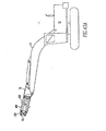
- Figure 42 is a schematic of a construction machine whereby the supplemental extension member has been added to the boom for a system designed to be utilized with an electric magnet for retrieving scrap;
- Figures 43A-43C illustrate in different positions a telescopic adapter module mounted to the boom of a construction machine
- Figure 44 is an exploded top view of a stick wing and a portion of an adapter
- Figure 45 is a side view of the stick wing illustrated in Figure 44 ;
- Figure 46 is an assembled top view of the arrangement illustrated in Figure 44 , with the locking pins retracted.
- Figure 47 is an assembled top view similar to the arrangement illustrated in Figure 46 , but with the locking pins extended to engage the adapter.
- FIG. 1 illustrates a construction machine 10 including a tractor 12 having an extension arm or boom 15 mounted thereupon and pivoted upon the tractor 12 with a hydraulic cylinder (not shown).
- Attached to the boom 15 is an extension arm or stick 20 operated by a hydraulic cylinder 25 attached between the boom 15 and the stick 20.
- a stick pivot attachment point 30 in conjunction with a stick linkage attachment point 35 provide points of attachment through which other tools and accessories may be attached to the stick 20.
- a hydraulic cylinder 40 in conjunction with a connecting linkage 45 act to move the stick linkage attachment point 35 to manipulate any accessory attached thereto. It is important to note that the stick pivot attachment point 30 and stick linkage attachment point 35 may significantly differ from one manufacturer to another such that one accessory or tool from a particular manufacturer may not be compatible to mount upon the stick of another manufacturer.
- the subject invention is intended to overcome this deficit by providing a modular system comprised of different functional modules that may be attached to the stick 20 through the use of a stick wing 50.
- the proximal end 51 of the stick wing 50 is connected to the stick 20 at the stick pivot attachment point 30 and at the stick linkage attachment point 35.
- the distal end 52 of the stick wing 50 includes a standardized proximal coupling arrangement 55 which may be used as a base for mounting any number of modular accessories or tools.
- Figures 3 and 4 which illustrates a construction machine 10 having a tractor 12 with only a boom 15 extending therefrom, a boom pivot attachment point 60 and a boom linkage attachment point 65, driven by the hydraulic cylinder 25, may be used as attachment points to receive the proximal end 71 of a boom wing 70 ( Figure 4 ).
- a distal end 72 of the boom wing 70 has a standardized proximal coupling arrangement 75 adapted to receive a variety of different modular accessories and tools.
- proximal end 51 of the stick wing 50 or the proximal end 71 of the boom wing 70 may be customized to accommodate the stick attachment points or the boom attachment points of any variety of different designs.
- Figures 5A and 5B illustrate a front and side view of a stick wing 50.
- the stick wing 50 is comprised of at least two plates 80, 81, each having at least two holes 82, 84 extending therethrough and spaced apart to define a hole pattern 85.
- the at least two opposing plates 80, 81 have mounting surfaces 86, 88 thereupon. It is the location of these plates 80, 81 and the associated holes 82, 84, which define the proximal coupling arrangement associated with the stick wing 50.
- the opposing plates 80, 81 are connected together through the use of a connecting member 90.
- each opposing plate 80, 81 has therethrough connecting bores 92, 94 spaced apart from one another on each plate 80, 81. It is the location and design of each of these connecting bores 92, 94 which provides a connection to the stick wing 50 of one manufacturer or another manufacturer.
- the stick wing 50 may be designed such that the size and the location of the connecting bores 92, 94 accommodate the attachment of the stick for different construction machines. While it may be necessary for a machine owner to have in inventory a variety of different stick wings 50, each designed to adapt for different construction machinery, it will not be necessary for the machine owner to purchase customized tools for each construction machine because, as will be seen, the modular system in accordance with the subject invention permits the use of a single set of tools upon machines from different manufacturers.
- Figures 6A and 6B illustrate a side view and a top view of a boom wing 70 having the standardized proximate coupling arrangement 75 and connecting bores 100, 102 extending through plates 104, 106 designed to be connected to the boom pivot attachment point 60 and boom linkage attachment point 65 illustrated in Figure 3 .
- the standardized proximal coupling arrangement 75 is identical to the standardized proximal coupling arrangement 55 previously described in association with the stick wing 50.
- the connecting bores 100, 102 may be sized and spaced appropriately to accommodate the attachment points for booms from manufactures of different construction machines.
- the boom wing 70 may be comprised of at least two opposing plates 104, 106 and each of these opposing plates 104, 106 may have mounting surfaces 108, 110.
- FIG. 7A and 7B A typical configuration for the proximal coupling arrangement and distal coupling arrangement herein discussed is illustrated in Figures 7A and 7B .
- an adapter 210 having a standardized proximal coupling arrangement 55 is illustrated in an exploded isometric view relative to the standardized distal coupling arrangement 115 of another adapter 211.
- the distal coupling arrangement 55 is comprised of opposing plates 80, 81 with a hole pattern 85 defined by holes 82, 84 which extend through both plates 80, 81.
- Each plate 80, 81 has a mounting surface 86, 88.
- the standardized distal coupling arrangement 115 is also comprised of at least two opposing plates 120, 122 with a hole pattern 124 defined by spaced-apart holes 126, 128.
- Each opposing plate 120, 122 has a mounting surface 130, 132 each which is generally aligned with mounting surface 86, 88 of the distal coupling arrangement 55.
- the opposing plates 80, 81 of the proximal coupling arrangement 55 are spaced in complimentary relationship with the opposing plates 120, 122 of the distal coupling arrangement 115 such that when the plates 80, 81 and 120, 122 are merged, the mounting surfaces 86, 130 and 88, 132 are adjacent to one another.
- the hole pattern 85 of the distal coupling arrangement 55 identified by holes 82, 84 matches the hole pattern 124 of the distal coupling arrangement 115 defined by holes 126, 128.
- the proximal coupling arrangement 55 is mated with the distal coupling arrangement 115 and the hole patterns 85, 124 align such that the retention pins 140, 142, 144, 146 may be inserted within the holes thereby securing the proximal coupling arrangement 55 within the distal coupling arrangement 115 as illustrated in Figure 7B .
- the retention pins 140, 142, 144, 146 each have bores 140a, 142a, 144a, 146a extending diametrically therethrough to accept locking pins (not shown) which are engaged through the bores 140a, 142a, 144a, 146a and through matching bores 140b, 142b, 144b, 146b extending through the adapter.
- the distal coupling arrangement 115 may further include with each opposing plate 120, 122 a reinforcement plate 148, 150 spaced next to the opposing plate 120, 122 to define slots 152, 154 therebetween.
- Each reinforcement plate 148, 150 has an identical hole pattern 156 to that of the hole pattern 124 associated with the opposing plate within the slot 152.
- each adapter modules 210, 211 has a standardized proximal coupling arrangement 55 and a standardized distal coupling arrangement 115 at each end.
- a plurality of adapter modules 210, 211 may be connected to one another in a string of modules.
- each different type of module hereinafter discussed will have one or both of the proximal coupling arrangement 55 and the distal coupling arrangement 115.
- these modules may be selected and matched with one another to provide a nearly limitless combination of different modules.
- each distal coupling arrangement and each proximal coupling arrangement, it is entirely possible for the configuration associated with one coupling arrangement to be associated with the other configuration.
- the distal coupling arrangement it is entirely possible for the distal coupling arrangement to be associated with reference number 115 and the proximal coupling arrangement to be associated with reference number 55.
- a standardized distal coupling arrangement 155 is mateable with a standardized proximal coupling arrangement 215 whereby the arrangement 155 is comprised of a hooking plate 160 with a hole 162 therethrough and a spaced-apart hook 164.
- the proximal coupling arrangement 215 is comprised of a hooked plate 166 with a spaced-apart hole 168 therethrough and a pivot pin 170, such that the hook 164 of the hooking plate 160 may engage the pivot pin 170 of the hooked plate 166 and the spaced-apart holes 162, 168 aligned to receive a support pin 172 extending therethrough, thereby providing a secure coupling between the distal coupling arrangement 155 and the proximal coupling arrangement 215.
- Figure 9 illustrates yet another coupling arrangement whereby a distal coupling arrangement 175 is connected to a proximal coupling arrangement 180.
- the distal coupling arrangement 175 is comprised of a plate 185 having a hole 187 extending therethrough and a wide protruding end 188.
- a projection 189 extends transversely to the end 188.
- the proximal coupling arrangement 180 is comprised of a plate 195 having a hole 197 extending therethrough and a matching wide receiving end 198.
- a recess 199 complimentary in shape to the projection 189 extends transversely within the end 198 in a direction corresponding to the projection 189.
- the wide protruding end 188 of the distal coupling arrangement 175 is brought into abutment with the matching wide receiving end 199 of the proximal coupling arrangement 215 wherein the holes 187,197 are aligned and the projection 189 is engaged with the recess 199.
- a retention bolt 201 is then placed within the holes 187, 197 to provide a secure coupling between the two coupling arrangements 175, 180.
- a stick wing 305 will be attached to an adapter 310.
- the stick wing 305 is comprised of a base 312 having at least one plate 314 with at least two holes 316, 318 extending therethrough defining a hole pattern 319.
- the adapter 310 is a module having a plate 328 with a hole pattern 330 extending therefrom matching that hole pattern 319 of the base plate 314 when the adapter 310 is positioned next to the stick wing 305.
- a manipulator rod 335 ( Figure 11 ) is moved back and forth by an actuator 340.
- Figure 11 illustrates the manipulator rod 335 in a retracted position.
- the actuator 340 may be, among other things, a hydraulic cylinder or an electric solenoid capable of moving the manipulator rod 335 from a retracted position illustrated in Figure 11 to an extended position illustrated in Figure 13A .
- the manipulator rod 335 extends from the stick wing 305 to engage a slot 342 in the tie bar 324 as illustrated in Figures 10 and 13A .
- FIG. 13B As illustrated in Figure 13B , once the manipulator rod 335 engages the slot 342 within the tie bar 324 the manipulator rod 335 may be retracted which at the same time will pull the tie bar 324 toward the adapter plate 328 thereby moving the locking posts 320, 322 ( Figure 12A ) into the holes 316, 318 ( Figure 10 ) of the wing 305 to secure the adapter 310 within the wing 305.
- Figures 12A , 13A illustrate the adapter 310 with the tie-bar 324 and the pins 320, 322 in the extended position while Figure 13C illustrates the stick wing 305 secured to the adapter 310 when the tie bar 324 is positioned in the retracted manner.
- locking pins 344, 346 may be used to secure the manipulator rod 335 within its retracted position relative to the adapter 310. By utilizing such an arrangement, it is possible to automatically actuate retention pins to engage or disengage modules associated with one another.
- each stick wing 305 and the adapter 310 has been discussed with a single based plate 314 and a single adapter plate 328.
- each stick wing 305 and adapter 310 has at least a pair of opposing plates to provide an arrangement which is symmetrical about the center of each the stick wing 305 and the adapter 310.
- Figures 10-13C illustrate what type of automatically actuated coupling system 300 whereby the locking posts mounted upon the adapter 310 are moved inwardly to engage the holes 316,318 of the stick wing 305.
- a stick wing 1305 will be attached to an adapter 1310.
- the stick wing 1305 is comprised of a base 1312 having at least one plate 1314 with at least two holes 1316, 1318 extending therethrough defining a hole pattern 1319.
- At least two locking posts 1320, 1322 are aligned with the holes 1316, 1318 and slidably mounted within a guide 1324 attached to the stick wing base.
- the adapter 1310 is a module having a plate 1328 with a hole pattern similar to that of hole pattern 1319 extending therefrom and matching the hole pattern 1319 of the base plate 1314 when the adapter 1310 is positioned next to the stick wing 1305.
- the locking pins 1320, 1322 are expanded outwardly to engage the holes 1316, 1318 from the retracted position illustrated in Figure 46 to the extended position illustrated in Figure 47 where the locking posts 1320, 1322 engage the adapter 1310.
- the locking posts 1320, 1322 may be hydraulically activated within the guide 1324. It should be noted that while the locking posts 1320, 1322 within the guide 1324 are associated with the stick wing 1305, it is entirely possible for the locking posts 1320, 1322 within the guide 1324 to be associated instead with the adapter 1310.
- FIGS 14A-14C illustrate a single adapter module 350 for connecting to a construction machine, wherein the module 350 has a body 352 with a first end 354 and a second end 356.
- a proximal coupling arrangement 55 similar to that illustrated in Figure 7A is associated with the first end 354 and a distal coupling arrangement 115 similar to that illustrated in Figure 7A is associated with the second end 356.
- the reference numbers applied in Figure 7A may also be applied to the elements in Figures 14A-14C .
- modules having a proximal coupling arrangement 55 on their first end and a distal coupling arrangement 115 on their second end may be arranged with one another and interlocked together in any desirable fashion. It is this interchangeability which provides the machine owner with maximum versatility and maximum efficiency in mixing and matching any number of a variety of different modules each having a proximal coupling arrangement and a distal coupling arrangement or both with each compatible with other modules.
- the module 350 illustrated in Figures 14A-14C is an adapter module which, as will be discussed, is intended to attach to a multi-tool.
- the adapter module 350 at its first end 354 includes a sleeve 401 with a longitudinal axis 403 and a passageway 405 extending therethrough along the longitudinal axis 403.
- the sleeve 401 is adapted to encompass the hydraulic cylinder portion 362 ( Figure 15 ) on the end of the multi-tool 360, which is used to operate the multi-tool 360.
- Figure 15 is an exploded side view of an arrangement whereby a stick wing 50 may be secured to an adapter module 350 which itself may be secured to a multi-tool 360.
- the multi-tool 360 includes a distal coupling arrangement 115 similar to that illustrated in the adapter module 350 of Figures 14A-14C .
- the body 352 includes a window 358.
- the window 358 provides access for the hydraulic lines which operate the multi-tool 360.
- Figure 16 illustrates the stick wing 50 with the adapter module 350 and a multi-tool 360 adjacent thereto.
- an extension module 365 which is similar to the adapter module 350 but exists purely to provide an extension between the stick wing 50 and another module.
- the extension module 365 includes a support structure 367 with a proximal coupling arrangement 55 associated with the first end 369 and a distal coupling arrangement 115 associated with the second end 371.
- FIG 17 illustrates a folding module 375 which is capable of pivoting such that the proximal coupling arrangement 55 and distal coupling arrangement 115 may be oriented relative to one another at different angles.
- the folding module 375 illustrated in Figure 17 is attached to an adapter module 350 at the first end 377 and to a stick wing 50 at the second end 379.
- the adapter module 350 is connected to the multi-tool 360.
- FIG 18 The configuration illustrated in Figure 18 is identical to the configuration illustrated in Figure 17 with the exception that the stick wing 50 is replaced by the boom wing 70 previously described. With this interchangeability, it should be appreciated that any modules that may be attached to the stick wing 50 illustrated in Figure 2 may also be attached to the boom wing 70 illustrated in Figure 4 . Nevertheless, returning to Figure 18 , the folding module 375 as described with respect to Figure 17 is capable of orienting the proximal coupling arrangement 55 at a different angle relative to the distal coupling arrangement 115.
- the folding module 375 is comprised of a two-part structure between the first end 377 and the second end 379.
- Figure 18 illustrates the folding adapter 375 in a straight pattern while Figure 19 illustrates the folding adapter 375 in a folded configuration.
- a first part 380 and a second part 382 are connected at one point 384 by a pivot 386 and are connected at a different point 388 by a driving cylinder 390 with a cylinder rod 392 such that the motion of the cylinder rod 392 changes the angular orientation of the first part 380 relative to the second part 382 and, as a result, changes the angular orientation of the adapter 350 relative to the boom wing 70 or to any other module to which the first part 380 may be attached.
- the arrangement illustrated in Figure 18 and in Figure 19 is a boom wing 70 attached to a folding module 375 which itself is attached to an adapter module 350.
- the folding adapter module 395 is comprised of a two-part structure wherein the first part is an adapter part 397 similar to the adapter module 350 previously described, but now, as will be seen is an integral part of the folding adapter module 395.
- the adapter part 397 is at the module first end 409.
- the folding adapter module 395 includes a first part 407 which has an adapter at the module first end 409 and includes similar features to the adapter module 350 described with respect to Figures 14A-14C .
- the first part 407 at the first end 409 includes a sleeve 401 with a longitudinal axis 403 and a passageway 405 extending therethrough along the longitudinal axis 403.
- the sleeve 401 is adapted to overlap a hydraulic cylinder portion 362 ( Figure 15 ) on the end of a tool 360.
- the second part is a folding member 411.
- the first part 407 and the second part 411 are connected to one another at one point 484 by a pivot 486 and at a different point 488 by a driving cylinder 490 with a cylinder rod 492 such that motion of the cylinder rod 492 changes the angular orientation of the first part 407 relative to the second part 411 and, as a result, changes the angular orientation of the boom wing 70 and the first end 409.
- Figures 21A-21D illustrate the versatility of a multi-tool 360 attached to a boom wing 70 by way of the folding adapter module 395 just described. Not only may the multi-tool 360 be rotated by the motion of the boom 15 as it is pivoted about the tractor (not shown), but additionally, through the use of the folding adapter module 395, the multi-tool 360 may have an additional joint of rotation such that, as illustrated in the sequence of Figures 20A-20C , the multi-tool 360 may be rotated through an angular range of approximately 135°.
- the modular design so far discussed is amenable to both a terminal module with a standardized coupling arrangement at only one end or an intermediate module which includes a standardized proximal coupling arrangement on one end and a distal coupling arrangement on another end.
- the extension module 365 is one example of an intermediate module which, on a first end 369, includes a standardized proximal coupling 55 and, on the second end 371, includes a standardized distal coupling 115 such that the extension module 365 may be secured between two other modules having an identical distal coupling arrangement or proximal coupling arrangement.
- the stick wing 50 includes a proximal coupling arrangement 55 which is secured to the distal coupling arrangement 115 at one end 371 of the extension module 365 while the proximal coupling arrangement 55 at the other end 369 of the extension module 365 is secured to the distal coupling arrangement 115 of the adapter module 350.
- the adapter module 350 is also an intermediate module used to accommodate the multi-tool 360.
- the multi-tool 360 has a front end 500 ( Figure 15 ) with a standardized proximal coupling arrangement 115 with the hydraulic cylinder portion 362 extending therefrom.
- the tool adapter 350 includes a sleeve 401 ( Figure 14B ) with a longitudinal axis 403 and a passageway 405 extending therethrough along the longitudinal axis 403.
- the sleeve 401 overlaps the hydraulic cylinder portion 362 ( Figure 15 ) and has a standardized proximal coupling arrangement 55 secured to the standardized distal coupling arrangement 115 of the multi-tool 360.
- the multi-tool 360 since it has only a standardized distal coupling arrangement 115, is considered to be a terminal module.
- the tool adapter 350 since it has both a standardized proximal coupling arrangement 115 and a standardized distal coupling arrangement 55, is considered to be ah intermediate module.
- An intermediate module may also be the extension module 365 previously discussed with respect to Figure 16 .
- An intermediate module may furthermore be the folding module 375 discussed with respect to Figures 17 and 18 .
- an intermediate module may be the folding adapter module 395 discussed with respect to Figures 19-20B .
- the intermediate module may also be a rotator module 510 that may, for example, be secured between the stick wing 50 and a bucket 512 having a distal coupling arrangement 115 thereupon.
- Figure 23 illustrates this arrangement assembled.
- the rotator module 510 is comprised of a rotator 514 between a first end 516 and a second end 518.
- the rotator 514 is comprised of a first part 520 rotatably connected to a second part 522 and further includes a driver 524 to mechanically rotate the first part 520 relative to the second part 522 thereby providing rotation between the module first end 516 and the module second end 518.
- the driver 524 rotates a driver gear which mates with an engaging gear r the second part 522 to provide relative rotation between the first part 520 and the second part 522.
- the driver 524 may be a hydraulically driven motor or in the alternative, may be an electric motor.
- the rotator module has a standardized distal coupling arrangement 115 at the first end 516 and a standardized proximal coupling arrangement 55 at the second end 518.
- Figures 22 and 23 illustrated a bucket 512 secured to the stick wing 50 through a rotator module 510, as illustrated in Figures 27 and 28 , it is entirely possible to mount the bucket 512 directly to the stick wing 50.
- Figures 29 and 30 illustrate an exploded and an assembled view of a claw 530 secured to the stick wing 50 through a rotator module 510.
- the claw 530 may be comprised of two tines 532, 534 pivotally secured to the body 536 of the claw and operated by hydraulic cylinders (not shown).
- FIGs 31 and 32 illustrate a hammer 540 secured to the stick wing 50 in a typical manner discussed within this application.
- a fitting plate 542 which includes a distal coupling arrangement 115 similar to those discussed herein.
- the hammer 540 may be mounted via the stick wing 50 to the stick 20 of a construction machine.
- a module having a proximal coupling arrangement on one end and a distal coupling arrangement on the opposing end has been referred to as an intermediate module
- a module having only a standardized distal coupling arrangement at one end may be referred to as a terminal module.
- the multi-tool 360 ( Figure 15 ) may be considered a terminal module as may the bucket 512 ( Figure 27 ), claw 530 ( Figure 29 ), and hammer 540 ( Figure 31 ).
- proximal coupling arrangements and distal coupling arrangements all compatible with one another. Such arrangements may typically be associated with a construction machine having a specific design capacity. However, it is entirely possible, depending upon the intended loading of a construction machine, to mate a coupling arrangement of one size with a coupling arrangement of a different size.
- a reducer module 550 is comprised of a first end 552 having a distal coupling arrangement 115 and a second end 554 having a proximal coupling arrangement but proportionately smaller to accommodate a proximal coupling arrangement also proportionately smaller for an adjacent module.
- the distance between slots in the distal coupling arrangement 115 is L1 and the distance between the center lines of the protrusions 557, 558 for the proximal coupling arrangement 55, which normally would extend within the slots 555, 556, is L2 which, as illustrated in Figure 34 , is less than L1.
- an enlarger module 560 may have a first end 562 with a distal coupling arrangement having a distance between slots 566, 567 of L3 with a second end 564 having a distance L4 between protrusions 568, 569 wherein L4 is greater than L3 and the standardized proximal coupling arrangement 55 is proportionately smaller than the standardized distal coupling arrangement 115.
- Figure 37 illustrates a construction machine 12 with a boom 15 and a stick 20 with a stick wing 50 attached thereto and a supplemental extension arm 570 attached to the wing 50.
- An electric magnet 575 is suspended by cables 577 from the supplemental extension arm 570.
- the electric magnet must be powered by an electric cable 578 extending all of the way from the tractor 12 to the magnet 575 and, as a result, the electrical cable 578 is exposed not only to the motion of the boom 15 and the stick 20, but furthermore, is exposed to the environment which may include demolition debris contacting or severing the electrical cable 578.
- Figure 38 illustrates a modified extension arm 579 which is identical to the stick 20 previously described with the exception of access to the internal frame of the modified extension arm 579 to protect the electrical cable,
- the modified extension arm 579 includes a first window 581 which provides access to the internal frame of the modified extension arm 579 and a second window 583 which together provide an entrance point and an exit point for the electrical cable 578.
- Supplemental extension arm 570 is illustrated in Figures 39 and 40 and just as with the modified extension arm 579, includes a first window 585 providing an entrance to the internal frame and a second window 587 providing an exit from the internal frame, thereby protecting the electrical cable 578 along the length of the supplemental extension arm 570. By doing so, the electrical cable 578 powering the magnet 575 is shielded along the segments of the construction machine where the cable 578 would normally be most vulnerable.
- the supplemental extension arm 570 has lifting slots 572, 573 extending therethrough suitable to accept the tines of a forklift or suitable to accept a cable sling for lifting. Such lifting slots may also be included in the modified extension arm 579 illustrated in Figure 38 .
- Figures 41A-41E illustrate the versatility of a construction machine 10 having a hydraulically activated boom 15, a hydraulically activated stick 20 and a hydraulically activated supplemental extension ann 570.
- the end 589 of the supplemental extension arm 570 is capable of being rotated 360°. Such a range of motion provides a machine operator with tremendous flexibility and versatility.
- Figure 42 illustrates a construction machine 12 with a boom 15 and a boom wing 70 attached thereto.
- the supplemental extension arm 570 is connected to the boom wing 70. Attached to the supplemental extension arm 570 through a support cable 577 is an electric magnet 575 powered by an electric cable 578. Therefore, it should be apparent that the supplemental extension arm 570 having an electric magnet 575 attached thereto may be secured to either the stick wing 50, as illustrated in Figure 37 , or the boom wing 70 as illustrated in Figure 42 .
- FIGS 43A-43C illustrate a telescopic adapter module 600 secured to the boom wing 70 of a construction machine 12. It should be appreciated that the telescopic adapter module 600 may also be mounted to a stick wing (not shown) or one of the intermediate adapters previously discussed herein.
- the telescopic adapter module 600 is comprised of a base 605 with an axially moving nested segment 610 extending from the base 605.
- Figure 43C illustrates a second nested segment 615 extending from the first nested segment 610.
- a standardized proximal coupling arrangement 55 of a particular size.
- a central cylinder 620 may be activated to extend the segments 610, 615 from the base 605.
- nested segment 615 is the only segment that includes the standardized proximal coupling arrangement 55.
- the base 605 includes a standardized proximal coupling arrangement 55 of one size
- the first nested segment 610 includes a standardized proximal coupling arrangement 55 of another size
- the second nested segment 615 includes yet another standardized proximal coupling arrangement 55 of yet another size.
- the telescopic adapter module 600 functions not only as a telescoping unit, but furthermore, provides the versatility to connect any number of different sized standardized distal coupling arrangements to the telescopic adapter module.
- the standardized proximal coupling arrangement 55 becomes progressively smaller in each segment 610, 615 extending away from the base 605.
- the embodiment illustrated in Figures 43A-43C includes two nested segments 610, 615 extending from a base 605 wherein, the furthermost end of each segment 610, 615 has a standardized proximal coupling arrangement 55.
- the subject invention is also directed to a method of interchanging one module with another module to provide versatility to a construction machine.
- the rotator module 510 may be secured between the stick wing 50 and the bucket 512 with the standardized coupling arrangements mating with one another.
- the bucket 512 may be attached directly to the stick wing 50.
- the modules described throughout this application may be attached in any number of combinations to provide configurations desired by the machine owner. It is also possible to remotely lock and unlock these modules to one another by aligning the hole patterns between a standardized distal coupling arrangement and a standardized proximal coupling arrangement and securing retention pins through the matching holes as described herein.
- the system in accordance with the subject invention, provides tremendous versatility for using the intermediate modules and the terminal modules to assemble from the stick or the boom of a construction machine and almost limitless number of different combinations to accommodate the needs of a machine operator since all of the intermediate modules and the terminal modules are compatible with one another through the standardized coupling arrangements.
Abstract
Description
- The present invention relates to a modular system for construction or demolition equipment which is adapted to be attached to a backhoe for attaching multiple tools, such as a heavy-duty metal cutting shear, a plate shear, a claw, a hammer, a bucket, a grapple or a concrete crusher.
- While the discussion hereafter will make reference to construction equipment, such equipment is also referred to as demolition equipment, scrap handling equipment and the like. The description of construction equipment is not intended to be restrictive of the equipment being referenced. Demolition equipment, such as heavy-duty metal cutting shears, plate shears, claws, hammers, buckets, grapples and concrete crushers have been mounted on backhoes powered by hydraulic cylinders for a variety of jobs in the demolition field. This equipment provides for the efficient cutting and handling of scrap. For example, in the dismantling of an industrial building, metal scrap in the form of various diameter pipes, structural I-beams, channels, angles, sheet metal plates and the like, must be efficiently severed and handled by heavy-duty metal shears. Such metal shears can also be utilized for reducing automobiles, truck frames, railroad cars and the like. The shears must be able to move and cut the metal scrap pieces regardless of the size or shape of the individual scrap pieces and without any significant damage to the shears. In the demolition of an industrial building, concrete crushing devices such as a concrete pulverizer or concrete crackers are also used to reduce the structure to manageable components which can be easily handled and removed from the site. A grapple is often utilized where handling of debris or work pieces is a primary function of the equipment. Historically, all these pieces of equipment represent distinct tools having significant independent capital costs. Consequently, the demolition industry has tended to develop one type of tool that can have the greatest possible utility and application.
- In general, construction equipment such as a backhoe is made up of a tractor having attached thereto a hydraulically operated boom and attached to the boom is a hydraulically operated stick. Each manufacturer of construction equipment provides a variety of attachments for their equipment, however, these attachments fit on only that manufacture's equipment. As a result, the purchasing of such attachments not only requires a dedicated commitment to a single manufacturer of construction equipment, but furthermore, puts the equipment owner at a significant disadvantage if the particular equipment manufacturer does not provide a particular attachment which may be needed by the equipment owner. It is inefficient and costly for an equipment owner to own and maintain two separate construction machines because certain attachments are made by one manufacturer and certain other attachments are made by another manufacturer.
- Additionally, different construction tasks require different configurations of the construction machine and depending upon the equipment manufacturer, there may be only a limited number of configurations possible for a specific construction machine. In the event that the machine owner desires a different configuration, then it may be necessary to approach the equipment manufacturer and ask for the specialized services associated with a customized part. This may become prohibitively expensive.
- A design is needed that will provide the machine owner with the flexibility of a single, set of attachments that may be suitable for use with any of a variety of construction machines from different manufacturers. Furthermore, a design is needed whereby a machine owner may have the flexibility to configure the attachments in any desirable sequence thereby maximizing the efficiency of the construction machine. Finally, a design is needed whereby it is possible for the machine owner to maximize the versatility of a construction machine by utilizing a plurality of different attachments that may be attached to the construction machine.
- A modular system for connecting any one of a plurality of modules to an extension arm of a construction machine comprising:
- a) a wing secured to the end of the extension arm, wherein the wing has a standardized proximal mounting arrangement; and
- b) a plurality of modules wherein each module has a first end with a standardized distal coupling arrangement adapted to be coupled with the standardized proximal coupling arrangement so that each module may be interchangeably secured to the wing.
- For use in a modular system for connecting any one of a plurality of modules together to an extension arm of a construction machine, the subject invention is also directed to an automatically actuated coupling system for securing the modules.
- Another embodiment of the subject invention is directed to a module for connecting to the extension arm of a construction machine. The module has a body with a first end and a second end with a proximal coupling arrangement associated with the first end and a distal coupling arrangement associated with the second end. The distal coupling arrangement has a plate with a hole pattern and the proximal coupling arrangement has a mating plate with an aligned matching hole pattern. The mounting arrangements are complimentary such that a second module having an identical one of the distal mounting arrangement or proximal mounting arrangement may be secured thereto.
- Another embodiment of the subject invention is directed to a method for remotely locking a structural module onto the extension arm of a construction tool. The arm and module each have matching hole patterns adapted to receive common retention pins moved by a hydraulic cylinder. The method comprises the steps of:
- a) aligning the hole patterns of the arm and module and
- b) activating the hydraulic cylinder to move the retention pins to engage the holes of each pattern, thereby securing the structural module to the extension arm.
- Another embodiment of the subject invention is directed to a method of interchangeably securing structural modules to the extension arm of a construction machine, wherein each module has a standardized coupling arrangement comprising the steps of mounting a first module to the standardized coupling arrangement of the extension arm, removing the first module from the extension arm, and mounting a second module having an identical standardized coupling arrangement to the extension arm.
- These and other advantages of the present invention will be clarified in the description of the preferred embodiments wherein like reference numerals represent like elements throughout.
-
Figure 1 is a schematic of a construction machine with the stick positioned to receive an attachment; -
Figure 2 is a schematic of the construction machine inFigure 1 with a stick wing mounted to the stick; -
Figure 3 is a schematic of a construction machine with the boom positioned to receive an attachment; -
Figure 4 is a schematic of the construction machine inFigure 3 with a boom wing attached to the boom; -
Figures 5A and 5B are a side view and a front view of a stick wing; -
Figures 6A and 6B are a side view and a top view of a boom wing; -
Figure 7A is an exploded isometric view of one embodiment of the coupling arrangement in accordance with the subject invention; -
Figure 7B is an assembled isometric view of the coupling arrangement illustrated inFigure 7A ; -
Figure 8 is a side view of an alternate embodiment of the coupling arrangement in accordance with the subject invention; -
Figure 9 is a side view of another alternate coupling arrangement in accordance with the subject invention; -
Figure 10 is an exploded view of a stick wing and a portion of an adapter; -
Figure 11 is the view of the stick inFigure 10 along lines "XI ― XI" inFigure 10 ; -
Figure 12A is a view of the adapter illustrated inFigure 10 along lines "XII-XII" with the tie bars extended; -
Figure 12B is a view of the adapter inFigure 12A with the tie bars retracted; -
Figures 13A-13C illustrate the sequential steps for securing the stick wing to the adapter; -
Figures 14A, 14B and 14C are front, top and left end views, respectively, of an adapter; -
Figures 15, 16 ,17 and 18 are exploded side views of different configurations of modules possible utilizing the design in accordance with the subject invention; -
Figure 19 is an assembled view of the exploded element inFigure 18 excluding the multi-tool; -
Figures 20A and 20B are side views of a folding adapter, in different positions, in accordance with the subject invention whereby the folding member and the adapter member are integral with one another; -
Figures 21A-21D are sequential side views of the motion possible utilizing the arrangement in accordance withFigure 18 ; -
Figure 22 is an exploded side view of a bucket associated with a stick wing and a rotator module therebetween; -
Figure 23 is a side view of the arrangement illustrated inFigure 22 but in an assembled configuration; -
Figures 24-26 are a side view, a left end view, and a right end view of a rotator module in accordance with the subject invention; -
Figure 27 is an exploded side view similar to that ofFigure 22 , however, without the rotator module between the stick wing and bucket; -
Figure 28 is a side view of an assembled configuration of the elements inFigure 27 ; -
Figure 29 is an exploded side view of a claw associated with a stick wing; -
Figure 30 is a side view of the arrangement inFigure 29 but in an assembled configuration; -
Figure 31 is an exploded side view of a hammer associated with a stick wing; -
Figure 32 is the hammer illustrated inFigure 31 , but assembled and mounted upon the stick of a construction machine; -
Figures 33 and 34 are a side view and a top view, respectively, of a reducer module; -
Figures 35 and 36 are a side view and a top view of an enlarger module; -
Figure 37 is a schematic of a construction machine whereby a supplemental extension member has been added to the stick for a system designed to be utilized with an electric magnet for retrieving scrap; -
Figure 38 is a modified extension arm having a portal extending therethrough for protecting the electric wire needed to control the magnet of the construction machine illustrated inFigure 37 ; -
Figures 39 and 40 are a top view and a side view, respectively, of the supplemental extension member; -
Figures 41A-41E illustrate a sequence of motion possible utilizing the elements illustrated on the construction machine inFigure 37 ; -
Figure 42 is a schematic of a construction machine whereby the supplemental extension member has been added to the boom for a system designed to be utilized with an electric magnet for retrieving scrap; -
Figures 43A-43C illustrate in different positions a telescopic adapter module mounted to the boom of a construction machine -
Figure 44 is an exploded top view of a stick wing and a portion of an adapter; -
Figure 45 is a side view of the stick wing illustrated inFigure 44 ; -
Figure 46 is an assembled top view of the arrangement illustrated inFigure 44 , with the locking pins retracted; and -
Figure 47 is an assembled top view similar to the arrangement illustrated inFigure 46 , but with the locking pins extended to engage the adapter. -
Figure 1 illustrates aconstruction machine 10 including atractor 12 having an extension arm orboom 15 mounted thereupon and pivoted upon thetractor 12 with a hydraulic cylinder (not shown). Attached to theboom 15 is an extension arm or stick 20 operated by ahydraulic cylinder 25 attached between theboom 15 and thestick 20. A stickpivot attachment point 30 in conjunction with a sticklinkage attachment point 35 provide points of attachment through which other tools and accessories may be attached to thestick 20. Ahydraulic cylinder 40 in conjunction with a connectinglinkage 45 act to move the sticklinkage attachment point 35 to manipulate any accessory attached thereto. It is important to note that the stickpivot attachment point 30 and sticklinkage attachment point 35 may significantly differ from one manufacturer to another such that one accessory or tool from a particular manufacturer may not be compatible to mount upon the stick of another manufacturer. - Directing attention to
Figure 2 , the subject invention is intended to overcome this deficit by providing a modular system comprised of different functional modules that may be attached to thestick 20 through the use of astick wing 50. The proximal end 51 of thestick wing 50 is connected to thestick 20 at the stickpivot attachment point 30 and at the sticklinkage attachment point 35. Thedistal end 52 of thestick wing 50 includes a standardizedproximal coupling arrangement 55 which may be used as a base for mounting any number of modular accessories or tools. - Additionally, directing attention to
Figures 3 and 4 , which illustrates aconstruction machine 10 having atractor 12 with only aboom 15 extending therefrom, a boompivot attachment point 60 and a boomlinkage attachment point 65, driven by thehydraulic cylinder 25, may be used as attachment points to receive theproximal end 71 of a boom wing 70 (Figure 4 ). Once again, adistal end 72 of theboom wing 70 has a standardizedproximal coupling arrangement 75 adapted to receive a variety of different modular accessories and tools. - Through the use of the
stick wing 50 and theboom wing 70 it is possible to adapt a large variety of different construction machines to accept a plurality of standardized attachments and tools thereby providing the maximum versatility for aconstruction machine 10 in the event a manufacturer does not provide a full complement of such attachments and/or tools, or, in the event a machine owner wisher to maximize the capacity of the machine. - In particular, the proximal end 51 of the
stick wing 50 or theproximal end 71 of theboom wing 70 may be customized to accommodate the stick attachment points or the boom attachment points of any variety of different designs. -
Figures 5A and 5B illustrate a front and side view of astick wing 50. In particular, thestick wing 50 is comprised of at least twoplates holes hole pattern 85. The at least two opposingplates surfaces plates holes stick wing 50. The opposingplates member 90. - Additionally, each opposing
plate bores plate bores stick wing 50 of one manufacturer or another manufacturer. Thestick wing 50 may be designed such that the size and the location of the connecting bores 92, 94 accommodate the attachment of the stick for different construction machines. While it may be necessary for a machine owner to have in inventory a variety ofdifferent stick wings 50, each designed to adapt for different construction machinery, it will not be necessary for the machine owner to purchase customized tools for each construction machine because, as will be seen, the modular system in accordance with the subject invention permits the use of a single set of tools upon machines from different manufacturers. -
Figures 6A and 6B illustrate a side view and a top view of aboom wing 70 having the standardizedproximate coupling arrangement 75 and connectingbores plates pivot attachment point 60 and boomlinkage attachment point 65 illustrated inFigure 3 . The standardizedproximal coupling arrangement 75 is identical to the standardizedproximal coupling arrangement 55 previously described in association with thestick wing 50. Additionally, the connectingbores stick wing 50, theboom wing 70 may be comprised of at least two opposingplates plates surfaces - A typical configuration for the proximal coupling arrangement and distal coupling arrangement herein discussed is illustrated in
Figures 7A and7B . Directing attention toFigure 7A , anadapter 210 having a standardizedproximal coupling arrangement 55 is illustrated in an exploded isometric view relative to the standardizeddistal coupling arrangement 115 of anotheradapter 211. In particular, and using reference numbers already used with respect to thestick wing 50 and theboom wing 70, thedistal coupling arrangement 55 is comprised of opposingplates hole pattern 85 defined byholes plates plate surface - The standardized
distal coupling arrangement 115 is also comprised of at least two opposingplates hole pattern 124 defined by spaced-apart holes plate surface surface distal coupling arrangement 55. The opposingplates proximal coupling arrangement 55 are spaced in complimentary relationship with the opposingplates distal coupling arrangement 115 such that when theplates surfaces hole pattern 85 of thedistal coupling arrangement 55 identified byholes hole pattern 124 of thedistal coupling arrangement 115 defined byholes proximal coupling arrangement 55 is mated with thedistal coupling arrangement 115 and thehole patterns proximal coupling arrangement 55 within thedistal coupling arrangement 115 as illustrated inFigure 7B . The retention pins 140, 142, 144, 146 each have bores 140a, 142a, 144a, 146a extending diametrically therethrough to accept locking pins (not shown) which are engaged through thebores bores - It is also possible as illustrated in
Figure 7A for thedistal coupling arrangement 115 to further include with each opposingplate 120, 122 areinforcement plate 148, 150 spaced next to the opposingplate slots reinforcement plate 148, 150 has anidentical hole pattern 156 to that of thehole pattern 124 associated with the opposing plate within theslot 152. - From inspection of
Figure 7A it should be appreciated that eachadapter modules proximal coupling arrangement 55 and a standardizeddistal coupling arrangement 115 at each end. As a result, a plurality ofadapter modules proximal coupling arrangement 55 and thedistal coupling arrangement 115. As a result, these modules may be selected and matched with one another to provide a nearly limitless combination of different modules. - Although throughout this application a specific configuration is described with respect to each distal coupling arrangement and each proximal coupling arrangement, it is entirely possible for the configuration associated with one coupling arrangement to be associated with the other configuration. In particular, with respect to
Figure 7A , it is entirely possible for the distal coupling arrangement to be associated withreference number 115 and the proximal coupling arrangement to be associated withreference number 55. - Although the proximal coupling arrangement and mating distal coupling arrangement heretofore disclosed will be the typical arrangement discussed throughout this application, it should be appreciated that there are multiple other coupling arrangements which may be used with the subject invention. In particular, as illustrated in
Figure 8 , a standardizeddistal coupling arrangement 155 is mateable with a standardizedproximal coupling arrangement 215 whereby thearrangement 155 is comprised of a hookingplate 160 with ahole 162 therethrough and a spaced-aparthook 164. Theproximal coupling arrangement 215 is comprised of ahooked plate 166 with a spaced-aparthole 168 therethrough and apivot pin 170, such that thehook 164 of the hookingplate 160 may engage thepivot pin 170 of thehooked plate 166 and the spaced-apart holes support pin 172 extending therethrough, thereby providing a secure coupling between thedistal coupling arrangement 155 and theproximal coupling arrangement 215. -
Figure 9 illustrates yet another coupling arrangement whereby adistal coupling arrangement 175 is connected to aproximal coupling arrangement 180. In particular, thedistal coupling arrangement 175 is comprised of aplate 185 having ahole 187 extending therethrough and a wideprotruding end 188. Aprojection 189 extends transversely to theend 188. Theproximal coupling arrangement 180 is comprised of aplate 195 having ahole 197 extending therethrough and a matching wide receivingend 198. Arecess 199 complimentary in shape to theprojection 189 extends transversely within theend 198 in a direction corresponding to theprojection 189. The wideprotruding end 188 of thedistal coupling arrangement 175 is brought into abutment with the matching wide receivingend 199 of theproximal coupling arrangement 215 wherein the holes 187,197 are aligned and theprojection 189 is engaged with therecess 199. Aretention bolt 201 is then placed within theholes coupling arrangements - What has so far been described is a distal mounting arrangement secured to a proximal mounting arrangement through the use of pins which are secured within mating hole patterns between the proximal mounting arrangement and the distal mounting arrangement. While it is entirely possible to manually secure these pins within the holes of the matching hole patterns, it is also possible to automate this function so that the pins may be hydraulically activated to be engaged or disengaged from the matching holes of the proximal mounting arrangement and distal mounting arrangement.
- In particular and directing attention to
Figures 10-13C , an automatically actuatedcoupling system 300 will be discussed. For purposes of discussion, as shown inFigure 10 , astick wing 305 will be attached to anadapter 310. Thestick wing 305 is comprised of a base 312 having at least oneplate 314 with at least twoholes hole pattern 319. - Directing attention to
Figures 10 and12A , and focusing on one half of acoupling arrangement posts holes tie bar 324. When thestick wing 305 is aligned with theadapter 310, theposts holes base plate 314. Theadapter 310 is a module having aplate 328 with ahole pattern 330 extending therefrom matching thathole pattern 319 of thebase plate 314 when theadapter 310 is positioned next to thestick wing 305. A manipulator rod 335 (Figure 11 ) is moved back and forth by anactuator 340.Figure 11 illustrates themanipulator rod 335 in a retracted position. Theactuator 340 may be, among other things, a hydraulic cylinder or an electric solenoid capable of moving themanipulator rod 335 from a retracted position illustrated inFigure 11 to an extended position illustrated inFigure 13A . Themanipulator rod 335 extends from thestick wing 305 to engage aslot 342 in thetie bar 324 as illustrated inFigures 10 and13A . As illustrated inFigure 13B , once themanipulator rod 335 engages theslot 342 within thetie bar 324 themanipulator rod 335 may be retracted which at the same time will pull thetie bar 324 toward theadapter plate 328 thereby moving the locking posts 320, 322 (Figure 12A ) into theholes 316, 318 (Figure 10 ) of thewing 305 to secure theadapter 310 within thewing 305.Figures 12A ,13A illustrate theadapter 310 with the tie-bar 324 and thepins Figure 13C illustrates thestick wing 305 secured to theadapter 310 when thetie bar 324 is positioned in the retracted manner. As a safety precaution, directing attention toFigure 13C , lockingpins manipulator rod 335 within its retracted position relative to theadapter 310. By utilizing such an arrangement, it is possible to automatically actuate retention pins to engage or disengage modules associated with one another. - It should be noted that in a preferred embodiment, the
stick wing 305 and theadapter 310 have been discussed with a single basedplate 314 and asingle adapter plate 328. However, it should be understood and as illustrated inFigures 10-13C , that eachstick wing 305 andadapter 310 has at least a pair of opposing plates to provide an arrangement which is symmetrical about the center of each thestick wing 305 and theadapter 310. It should also be noted that while, with respect toFigures 10 ― 13C, only one side of the arrangement was discussed, there are four retention pins in a typical adapter coupling in a symmetric arrangement topins Figure 12A . -
Figures 10-13C illustrate what type of automatically actuatedcoupling system 300 whereby the locking posts mounted upon theadapter 310 are moved inwardly to engage the holes 316,318 of thestick wing 305. - Directing attention to
Figures 44-47 , it is also possible for the locking posts to move outwardly. In particular, as automatically actuatedcoupling system 1300 will be discussed. For purposes of discussion as shown inFigure 44 , astick wing 1305 will be attached to anadapter 1310. Thestick wing 1305 is comprised of abase 1312 having at least oneplate 1314 with at least twoholes hole pattern 1319. At least two lockingposts holes stick wing 1305 is aligned with theadapter 1310, theposts holes base plate 1314. Theadapter 1310 is a module having aplate 1328 with a hole pattern similar to that ofhole pattern 1319 extending therefrom and matching thehole pattern 1319 of thebase plate 1314 when theadapter 1310 is positioned next to thestick wing 1305. When thestick wing 1305 is properly positioned adjacent to theadapter 1310, the locking pins 1320, 1322 are expanded outwardly to engage theholes Figure 46 to the extended position illustrated inFigure 47 where the lockingposts adapter 1310. The locking posts 1320, 1322 may be hydraulically activated within the guide 1324. It should be noted that while thelocking posts stick wing 1305, it is entirely possible for thelocking posts adapter 1310. - Briefly returning to
Figures 7A and7B , described therein was aproximal coupling arrangement 55 mateable with adistal coupling arrangement 115.Figures 14A-14C illustrate asingle adapter module 350 for connecting to a construction machine, wherein themodule 350 has abody 352 with afirst end 354 and asecond end 356. Aproximal coupling arrangement 55 similar to that illustrated inFigure 7A is associated with thefirst end 354 and adistal coupling arrangement 115 similar to that illustrated inFigure 7A is associated with thesecond end 356. The reference numbers applied inFigure 7A may also be applied to the elements inFigures 14A-14C . It should be appreciated that other modules having aproximal coupling arrangement 55 on their first end and adistal coupling arrangement 115 on their second end may be arranged with one another and interlocked together in any desirable fashion. It is this interchangeability which provides the machine owner with maximum versatility and maximum efficiency in mixing and matching any number of a variety of different modules each having a proximal coupling arrangement and a distal coupling arrangement or both with each compatible with other modules. - The
module 350 illustrated inFigures 14A-14C is an adapter module which, as will be discussed, is intended to attach to a multi-tool. Theadapter module 350 at itsfirst end 354 includes asleeve 401 with alongitudinal axis 403 and apassageway 405 extending therethrough along thelongitudinal axis 403. Thesleeve 401 is adapted to encompass the hydraulic cylinder portion 362 (Figure 15 ) on the end of themulti-tool 360, which is used to operate themulti-tool 360. -
Figure 15 is an exploded side view of an arrangement whereby astick wing 50 may be secured to anadapter module 350 which itself may be secured to amulti-tool 360. Themulti-tool 360 includes adistal coupling arrangement 115 similar to that illustrated in theadapter module 350 ofFigures 14A-14C . - Briefly returning to
Figures 14A-14C , thebody 352 includes awindow 358. When theadapter module 350 is secured to themulti-tool 360, thewindow 358 provides access for the hydraulic lines which operate themulti-tool 360. -
Figure 16 illustrates thestick wing 50 with theadapter module 350 and amulti-tool 360 adjacent thereto. Between thestick wing 50 and theadapter module 350 is anextension module 365 which is similar to theadapter module 350 but exists purely to provide an extension between thestick wing 50 and another module. Theextension module 365 includes asupport structure 367 with aproximal coupling arrangement 55 associated with thefirst end 369 and adistal coupling arrangement 115 associated with thesecond end 371. - While the
adapter module 350 and theextension module 365 provide rigid structures between the proximal coupling arrangement and the distal coupling arrangement of each of these modules,Figure 17 illustrates afolding module 375 which is capable of pivoting such that theproximal coupling arrangement 55 anddistal coupling arrangement 115 may be oriented relative to one another at different angles. Thefolding module 375 illustrated inFigure 17 is attached to anadapter module 350 at thefirst end 377 and to astick wing 50 at thesecond end 379. Just as before, theadapter module 350 is connected to themulti-tool 360. - The configuration illustrated in
Figure 18 is identical to the configuration illustrated inFigure 17 with the exception that thestick wing 50 is replaced by theboom wing 70 previously described. With this interchangeability, it should be appreciated that any modules that may be attached to thestick wing 50 illustrated inFigure 2 may also be attached to theboom wing 70 illustrated inFigure 4 . Nevertheless, returning toFigure 18 , thefolding module 375 as described with respect toFigure 17 is capable of orienting theproximal coupling arrangement 55 at a different angle relative to thedistal coupling arrangement 115. - Directing attention to
Figures 18 and19 , thefolding module 375 is comprised of a two-part structure between thefirst end 377 and thesecond end 379.Figure 18 illustrates thefolding adapter 375 in a straight pattern whileFigure 19 illustrates thefolding adapter 375 in a folded configuration. Afirst part 380 and asecond part 382 are connected at onepoint 384 by apivot 386 and are connected at adifferent point 388 by a drivingcylinder 390 with acylinder rod 392 such that the motion of thecylinder rod 392 changes the angular orientation of thefirst part 380 relative to thesecond part 382 and, as a result, changes the angular orientation of theadapter 350 relative to theboom wing 70 or to any other module to which thefirst part 380 may be attached. - The arrangement illustrated in
Figure 18 and inFigure 19 is aboom wing 70 attached to afolding module 375 which itself is attached to anadapter module 350. To conserve space and to minimize the number of parts, it is entirely possible to consolidate theboom wing 70 and thefolding module 375 illustrated inFigures 18 and19 to generate afolding adapter module 395 illustrated inFigures 20A and 20B . Thefolding adapter module 395 is comprised of a two-part structure wherein the first part is anadapter part 397 similar to theadapter module 350 previously described, but now, as will be seen is an integral part of thefolding adapter module 395. Theadapter part 397 is at the modulefirst end 409. - The
folding adapter module 395 includes afirst part 407 which has an adapter at the modulefirst end 409 and includes similar features to theadapter module 350 described with respect toFigures 14A-14C . In particular, thefirst part 407 at thefirst end 409 includes asleeve 401 with alongitudinal axis 403 and apassageway 405 extending therethrough along thelongitudinal axis 403. Thesleeve 401 is adapted to overlap a hydraulic cylinder portion 362 (Figure 15 ) on the end of atool 360. - The second part is a
folding member 411. Thefirst part 407 and thesecond part 411 are connected to one another at onepoint 484 by apivot 486 and at adifferent point 488 by a drivingcylinder 490 with acylinder rod 492 such that motion of thecylinder rod 492 changes the angular orientation of thefirst part 407 relative to thesecond part 411 and, as a result, changes the angular orientation of theboom wing 70 and thefirst end 409. -
Figures 21A-21D illustrate the versatility of amulti-tool 360 attached to aboom wing 70 by way of thefolding adapter module 395 just described. Not only may themulti-tool 360 be rotated by the motion of theboom 15 as it is pivoted about the tractor (not shown), but additionally, through the use of thefolding adapter module 395, themulti-tool 360 may have an additional joint of rotation such that, as illustrated in the sequence ofFigures 20A-20C , themulti-tool 360 may be rotated through an angular range of approximately 135°. While such a rotation may be available utilizing a standard boom/stick combination, the space required for this arrangement coupled with amulti-tool 360 would be prohibitive and, as a result, thefolding adapter module 395 provides a solution not heretofore available in previous designs. - The modular design so far discussed is amenable to both a terminal module with a standardized coupling arrangement at only one end or an intermediate module which includes a standardized proximal coupling arrangement on one end and a distal coupling arrangement on another end.
- Returning attention to
Figure 16 , theextension module 365 is one example of an intermediate module which, on afirst end 369, includes a standardizedproximal coupling 55 and, on thesecond end 371, includes a standardizeddistal coupling 115 such that theextension module 365 may be secured between two other modules having an identical distal coupling arrangement or proximal coupling arrangement. As illustrated inFigure 16 , thestick wing 50 includes aproximal coupling arrangement 55 which is secured to thedistal coupling arrangement 115 at oneend 371 of theextension module 365 while theproximal coupling arrangement 55 at theother end 369 of theextension module 365 is secured to thedistal coupling arrangement 115 of theadapter module 350. As such, theadapter module 350 is also an intermediate module used to accommodate themulti-tool 360. - In order to accommodate the
proximal coupling arrangement 55 of theadapter module 350, themulti-tool 360 has a front end 500 (Figure 15 ) with a standardizedproximal coupling arrangement 115 with thehydraulic cylinder portion 362 extending therefrom. As previously mentioned, thetool adapter 350 includes a sleeve 401 (Figure 14B ) with alongitudinal axis 403 and apassageway 405 extending therethrough along thelongitudinal axis 403. Thesleeve 401 overlaps the hydraulic cylinder portion 362 (Figure 15 ) and has a standardizedproximal coupling arrangement 55 secured to the standardizeddistal coupling arrangement 115 of themulti-tool 360. In this arrangement, themulti-tool 360, since it has only a standardizeddistal coupling arrangement 115, is considered to be a terminal module. On the other hand, thetool adapter 350, since it has both a standardizedproximal coupling arrangement 115 and a standardizeddistal coupling arrangement 55, is considered to be ah intermediate module. - An intermediate module may also be the
extension module 365 previously discussed with respect toFigure 16 . An intermediate module may furthermore be thefolding module 375 discussed with respect toFigures 17 and 18 . Additionally, an intermediate module may be thefolding adapter module 395 discussed with respect toFigures 19-20B . - Directing attention to
Figures 22 and 23 , the intermediate module may also be arotator module 510 that may, for example, be secured between thestick wing 50 and abucket 512 having adistal coupling arrangement 115 thereupon.Figure 23 illustrates this arrangement assembled. - Directing attention to
Figures 24-26 , therotator module 510 is comprised of arotator 514 between afirst end 516 and asecond end 518. Therotator 514 is comprised of afirst part 520 rotatably connected to asecond part 522 and further includes adriver 524 to mechanically rotate thefirst part 520 relative to thesecond part 522 thereby providing rotation between the modulefirst end 516 and the modulesecond end 518. Thedriver 524 rotates a driver gear which mates with an engaging gear r thesecond part 522 to provide relative rotation between thefirst part 520 and thesecond part 522. Thedriver 524 may be a hydraulically driven motor or in the alternative, may be an electric motor. The rotator module has a standardizeddistal coupling arrangement 115 at thefirst end 516 and a standardizedproximal coupling arrangement 55 at thesecond end 518. - Although
Figures 22 and 23 illustrated abucket 512 secured to thestick wing 50 through arotator module 510, as illustrated inFigures 27 and 28 , it is entirely possible to mount thebucket 512 directly to thestick wing 50. -
Figures 29 and 30 illustrate an exploded and an assembled view of aclaw 530 secured to thestick wing 50 through arotator module 510. Theclaw 530 may be comprised of twotines 532, 534 pivotally secured to thebody 536 of the claw and operated by hydraulic cylinders (not shown). -
Figures 31 and 32 illustrate ahammer 540 secured to thestick wing 50 in a typical manner discussed within this application. Depending upon the manufacturer of the hammer, 540, it may be necessary to install afitting plate 542 which includes adistal coupling arrangement 115 similar to those discussed herein. With such an arrangement, thehammer 540 may be mounted via thestick wing 50 to thestick 20 of a construction machine. Note the hydraulic cylinder 40 (Figure 2 ) has been removed inFigure 32 . - As previously stated, while a module having a proximal coupling arrangement on one end and a distal coupling arrangement on the opposing end has been referred to as an intermediate module, a module having only a standardized distal coupling arrangement at one end may be referred to as a terminal module. In particular, the multi-tool 360 (
Figure 15 ) may be considered a terminal module as may the bucket 512 (Figure 27 ), claw 530 (Figure 29 ), and hammer 540 (Figure 31 ). - What has so far been discussed are proximal coupling arrangements and distal coupling arrangements all compatible with one another. Such arrangements may typically be associated with a construction machine having a specific design capacity. However, it is entirely possible, depending upon the intended loading of a construction machine, to mate a coupling arrangement of one size with a coupling arrangement of a different size. In particular and with attention directed to
Figures 33 and 34 , areducer module 550 is comprised of afirst end 552 having adistal coupling arrangement 115 and asecond end 554 having a proximal coupling arrangement but proportionately smaller to accommodate a proximal coupling arrangement also proportionately smaller for an adjacent module. In particular, the distance between slots in thedistal coupling arrangement 115 is L1 and the distance between the center lines of theprotrusions proximal coupling arrangement 55, which normally would extend within theslots Figure 34 , is less than L1. - In the alternative, an
enlarger module 560 may have afirst end 562 with a distal coupling arrangement having a distance betweenslots second end 564 having a distance L4 betweenprotrusions proximal coupling arrangement 55 is proportionately smaller than the standardizeddistal coupling arrangement 115. - It should be noted that the size and the spacing of the mounting holes for each adapter will also change depending on the size of the coupling arrangement.
-
Figure 37 illustrates aconstruction machine 12 with aboom 15 and astick 20 with astick wing 50 attached thereto and asupplemental extension arm 570 attached to thewing 50. Anelectric magnet 575 is suspended bycables 577 from thesupplemental extension arm 570. The electric magnet must be powered by anelectric cable 578 extending all of the way from thetractor 12 to themagnet 575 and, as a result, theelectrical cable 578 is exposed not only to the motion of theboom 15 and thestick 20, but furthermore, is exposed to the environment which may include demolition debris contacting or severing theelectrical cable 578. As a result,Figure 38 illustrates a modifiedextension arm 579 which is identical to thestick 20 previously described with the exception of access to the internal frame of the modifiedextension arm 579 to protect the electrical cable, In particular, the modifiedextension arm 579 includes afirst window 581 which provides access to the internal frame of the modifiedextension arm 579 and asecond window 583 which together provide an entrance point and an exit point for theelectrical cable 578. -
Supplemental extension arm 570 is illustrated inFigures 39 and 40 and just as with the modifiedextension arm 579, includes afirst window 585 providing an entrance to the internal frame and asecond window 587 providing an exit from the internal frame, thereby protecting theelectrical cable 578 along the length of thesupplemental extension arm 570. By doing so, theelectrical cable 578 powering themagnet 575 is shielded along the segments of the construction machine where thecable 578 would normally be most vulnerable. Thesupplemental extension arm 570 has liftingslots extension arm 579 illustrated inFigure 38 . -
Figures 41A-41E illustrate the versatility of aconstruction machine 10 having a hydraulically activatedboom 15, a hydraulically activatedstick 20 and a hydraulically activatedsupplemental extension ann 570. As may be seen in the sequence presented inFigures 41A-41E , theend 589 of thesupplemental extension arm 570 is capable of being rotated 360°. Such a range of motion provides a machine operator with tremendous flexibility and versatility. -
Figure 42 illustrates aconstruction machine 12 with aboom 15 and aboom wing 70 attached thereto. Thesupplemental extension arm 570 is connected to theboom wing 70. Attached to thesupplemental extension arm 570 through asupport cable 577 is anelectric magnet 575 powered by anelectric cable 578. Therefore, it should be apparent that thesupplemental extension arm 570 having anelectric magnet 575 attached thereto may be secured to either thestick wing 50, as illustrated inFigure 37 , or theboom wing 70 as illustrated inFigure 42 . -
Figures 43A-43C illustrate atelescopic adapter module 600 secured to theboom wing 70 of aconstruction machine 12. It should be appreciated that thetelescopic adapter module 600 may also be mounted to a stick wing (not shown) or one of the intermediate adapters previously discussed herein. - The
telescopic adapter module 600 is comprised of a base 605 with an axially moving nestedsegment 610 extending from thebase 605. As can be seen inFigures 43A-43B , multiple nesting segments are possible. In particular,Figure 43C illustrates a second nestedsegment 615 extending from the first nestedsegment 610. At the furthermost end of nestedsegment 615 is a standardizedproximal coupling arrangement 55 of a particular size. Acentral cylinder 620 may be activated to extend thesegments base 605. In one embodiment of the subject invention, nestedsegment 615 is the only segment that includes the standardizedproximal coupling arrangement 55. However, in another embodiment, thebase 605 includes a standardizedproximal coupling arrangement 55 of one size, the first nestedsegment 610 includes a standardizedproximal coupling arrangement 55 of another size and, as mentioned, the second nestedsegment 615 includes yet another standardizedproximal coupling arrangement 55 of yet another size. As a result, thetelescopic adapter module 600 functions not only as a telescoping unit, but furthermore, provides the versatility to connect any number of different sized standardized distal coupling arrangements to the telescopic adapter module. As seen inFigure 43C , the standardizedproximal coupling arrangement 55 becomes progressively smaller in eachsegment base 605. The embodiment illustrated inFigures 43A-43C includes two nestedsegments segment proximal coupling arrangement 55. - The subject invention is also directed to a method of interchanging one module with another module to provide versatility to a construction machine. In particular, and with attention directed to
Figures 22-23 , therotator module 510 may be secured between thestick wing 50 and thebucket 512 with the standardized coupling arrangements mating with one another. Additionally, with attention directed toFigures 27-28 , thebucket 512 may be attached directly to thestick wing 50. As a result, it should be apparent that the modules described throughout this application may be attached in any number of combinations to provide configurations desired by the machine owner. It is also possible to remotely lock and unlock these modules to one another by aligning the hole patterns between a standardized distal coupling arrangement and a standardized proximal coupling arrangement and securing retention pins through the matching holes as described herein. - It should now be appreciated that the system, in accordance with the subject invention, provides tremendous versatility for using the intermediate modules and the terminal modules to assemble from the stick or the boom of a construction machine and almost limitless number of different combinations to accommodate the needs of a machine operator since all of the intermediate modules and the terminal modules are compatible with one another through the standardized coupling arrangements.
- While specific embodiments of the invention have been described in detail, it will be appreciated by those skilled in the art that various modifications and alternatives to those details could be developed in light of the overall teachings of the disclosure. The presently preferred embodiments described herein are meant to be illustrative only and not limiting as to the scope of the invention which is to be given the full breadth of the appended claims and any and all equivalents thereof.
Claims (15)
- A modular system for connecting any one of a plurality of modules to an extension arm of a construction machine comprising:a) a wing secured to the end of the extension arm, for example wherein the extension arm is a boom on the construction machine or wherein the extension arm is a stick on the construction machine, wherein the wing has a standardized proximal mounting arrangement;b) a first plurality of modules, wherein each module has a first end adapted to be secured to the wing and comprises a standardized distal coupling arrangement adapted to be coupled with the standardized proximal coupling arrangement so that each module may be interchangeably secured to the wing.
- The system according to claim 1, wherein the distal coupling arrangement is comprised of a plate with a hole pattern and the proximal coupling arrangement is comprised of a mating plate with an aligned matching hole pattern, wherein the plates are secured together with retention pins extending through matching holes.
- The system according to claim 2, wherein there are at least two spaced apart holes within each hole pattern.
- The system according to claim 2 or 3, wherein each coupling arrangement is comprised of at least two opposing plates having mounting surfaces and wherein the opposing plates of each arrangement are spaced in complimentary relationship to one another such that when the plates are merged the mounting surfaces are adjacent to one another, the hole patterns are aligned and bolts may be placed through the holes to secured the plates together.
- The system according to claim 2, 3 or 4,
wherein one of the coupling arrangements further includes with each opposing plate a reinforcement plate spaced next to the opposing plate to define a slot therebetween, wherein the reinforcement plate has an identical hole pattern such that the plate of the other coupling arrangement fits within the slot and is secured therebetween for improved support. - The system according to any of claims 1-5,
wherein either the distal coupling arrangement or the proximal coupling arrangement is comprised of a hooking plate with a hole therethrough and a spaced apart hook and the other coupling arrangement is comprised of a hooked plate with a spaced apart hole therethrough and a pivot pin, such that the hook of the hooking plate may engage the pivot pin of the hooked plate and the spaced apart holes aligned to receive a support pin, thereby providing a secure coupling between the two coupling arrangements. - The system according to any of claims 1-6,
wherein either the distal coupling arrangement or the proximal coupling arrangement is comprised of a plate having a hole extending therethrough and a wide protruding end with a protrusion extending transversely therefrom and the other of the arrangements is comprised of a plate having hole extending therethrough and a matching wide receiving end with a recess extending transversely therein, wherein the recess has a complimentary shape to the protrusion, such that when the wide end are brought in abutment with one another, the protrusion engages the recess, the holes are aligned and a retention bolt placed therein the holes to provide a secure coupling between the two coupling arrangements. - The system according to any of claims 1-7,
wherein the module is either an intermediate module or a terminal module with the distal coupling arrangement,
wherein the terminal module is a multi-tool, a bucket, a claw or a hammer. - The system according to claim 8, wherein the terminal module is a supplemental extension arm.
- The system according to claim 9, further including an electric magnet suspended from the supplemental extension arm.
- The system according to claim 10, wherein the supplemental extension arm has an internal opening extending along the length and further including an electrical wire extending therein and connected to the magnet to power the magnet.
- The system according to claim 8, further including an intermediate module from the group consisting of an extension module, a folding module, a folding adapter module, a rotator module, a reducer module, an enlarger module, and a telescopic module.
- The system according to any of claims 1-12 comprising:a) a base having at least one plate with at least two holes extending therethrough,b) at least two locking posts aligned with the holes, wherein the posts are slidable within the holes of the base plate, preferably wherein the at least two locking posts are secured to a tie rod and wherein the driver is a manipulator rod extending from the base to engage the tie rod for moving the locking posts, or wherein the at least two locking posts are extended and retracted through a hydraulic cylinder,c) a module having a plate with a matching hole pattern to that of the base plate when the module is positioned next to the base plate;d) a driver for moving the locking posts back and forth in and out of the holes to secure the module to the base.
- The coupling system according to claim 13,
wherein at least two locking posts are secured to a tie rod and wherein the driver is a manipulator rod extending from the base to engage the tie rod for moving the locking posts. - The coupling system according to claim 14,
wherein the at leasttwo locking posts are extended and retracted through a hydraulic cylinder.
Applications Claiming Priority (2)
| Application Number | Priority Date | Filing Date | Title |
|---|---|---|---|
| US11/331,818 US7975944B2 (en) | 1999-10-15 | 2006-01-13 | Modular system for connecting attachments to a construction machine |
| EP07709770A EP1984573A2 (en) | 2006-01-13 | 2007-01-12 | Modular system for connecting attachments to a construction machine |
Related Parent Applications (2)
| Application Number | Title | Priority Date | Filing Date |
|---|---|---|---|
| EP07709770.7 Division | 2007-01-12 | ||
| EP07709770A Division EP1984573A2 (en) | 2006-01-13 | 2007-01-12 | Modular system for connecting attachments to a construction machine |
Publications (2)
| Publication Number | Publication Date |
|---|---|
| EP2426274A2 true EP2426274A2 (en) | 2012-03-07 |
| EP2426274A3 EP2426274A3 (en) | 2015-01-21 |
Family
ID=38016734
Family Applications (5)
| Application Number | Title | Priority Date | Filing Date |
|---|---|---|---|
| EP11190013.0A Withdrawn EP2426275A3 (en) | 2006-01-13 | 2007-01-12 | Modular system for connecting attachments to a construction machine |
| EP11190007.2A Withdrawn EP2426273A3 (en) | 2006-01-13 | 2007-01-12 | Modular system for connecting attachments to a construction machine |
| EP11190014A Withdrawn EP2426276A2 (en) | 2006-01-13 | 2007-01-12 | Modular system for connecting attachments to a construction machine |
| EP07709770A Withdrawn EP1984573A2 (en) | 2006-01-13 | 2007-01-12 | Modular system for connecting attachments to a construction machine |
| EP11190011.4A Withdrawn EP2426274A3 (en) | 2006-01-13 | 2007-01-12 | Modular system for connecting attachments to a construction machine |
Family Applications Before (4)
| Application Number | Title | Priority Date | Filing Date |
|---|---|---|---|
| EP11190013.0A Withdrawn EP2426275A3 (en) | 2006-01-13 | 2007-01-12 | Modular system for connecting attachments to a construction machine |
| EP11190007.2A Withdrawn EP2426273A3 (en) | 2006-01-13 | 2007-01-12 | Modular system for connecting attachments to a construction machine |
| EP11190014A Withdrawn EP2426276A2 (en) | 2006-01-13 | 2007-01-12 | Modular system for connecting attachments to a construction machine |
| EP07709770A Withdrawn EP1984573A2 (en) | 2006-01-13 | 2007-01-12 | Modular system for connecting attachments to a construction machine |
Country Status (5)
| Country | Link |
|---|---|
| US (2) | US7975944B2 (en) |
| EP (5) | EP2426275A3 (en) |
| JP (1) | JP5205279B2 (en) |
| CA (1) | CA2636969C (en) |
| WO (1) | WO2007084384A2 (en) |
Families Citing this family (26)
| Publication number | Priority date | Publication date | Assignee | Title |
|---|---|---|---|---|
| US9074352B2 (en) | 2006-03-27 | 2015-07-07 | John R. Ramun | Universal control scheme for mobile hydraulic equipment and method for achieving the same |
| US7975475B2 (en) * | 2006-03-27 | 2011-07-12 | Ramun John R | Universal control scheme for mobile hydraulic equipment and method for achieving the same |
| CN101470083B (en) * | 2007-12-27 | 2011-08-03 | 同方威视技术股份有限公司 | Novel folding arm mechanism used for vehicle-mounted radiation imaging system |
| GB0815503D0 (en) * | 2008-08-23 | 2008-10-01 | Fox P J | Rapid fit extension arm |
| JP4806049B2 (en) * | 2009-03-27 | 2011-11-02 | 日立建機株式会社 | Two-member connecting device |
| JP2014502686A (en) * | 2011-01-13 | 2014-02-03 | ラマン,ジョン,アール | Modular system for connecting attachments to construction machinery |
| US10798877B2 (en) * | 2011-05-05 | 2020-10-13 | Steven J Terrell | Apparatus for aerial tool configurations |
| US11690324B2 (en) * | 2011-05-05 | 2023-07-04 | Steven J Terrell | Apparatus for aerial tool configurations |
| US9004845B2 (en) * | 2011-08-26 | 2015-04-14 | Gilbert Bernier | Inverting of attachments for working machines having front end loader configurations |
| EP2749698B1 (en) * | 2011-10-05 | 2016-08-31 | Caterpillar Work Tools B. V. | Demolition apparatus |
| USD752114S1 (en) * | 2012-06-04 | 2016-03-22 | Caterpillar Work Tools B.V. | Multi-processor and modular wear protection system |
| WO2014039041A1 (en) * | 2012-09-06 | 2014-03-13 | Build Strong Llc | Modular industrial vehicle |
| US20140165355A1 (en) * | 2012-12-18 | 2014-06-19 | Smith Truck Crane & Equipment, Inc. | Jig manipulator |
| US20140212210A1 (en) * | 2013-01-25 | 2014-07-31 | Caterpillar Inc. | Tool coupler having a modular frame construction |
| AT514120A1 (en) * | 2013-04-12 | 2014-10-15 | Leicht Helene | Device for increasing the reach of an excavator and using the same |
| JP6225614B2 (en) * | 2013-09-30 | 2017-11-08 | コベルコ建機株式会社 | Boom and work machine equipped with the same |
| US9617711B2 (en) * | 2014-03-21 | 2017-04-11 | Donald J. MURTHA | Excavator |
| NO337351B1 (en) * | 2014-08-21 | 2016-03-21 | Duun Ind As | Coupling device for front loads on construction machinery and machinery for agriculture and forestry. |
| WO2016116894A1 (en) * | 2015-01-22 | 2016-07-28 | Cosben S.R.L. | Kit of telescopic arms for in-depth vertical machining |
| US9809945B1 (en) * | 2015-06-08 | 2017-11-07 | Robert Middleton | Method, apparatus, and kit for providing an adapter on earth moving equipment |
| US10378174B2 (en) * | 2016-09-20 | 2019-08-13 | Caterpillar Inc. | Interface for coupling work tool to machine |
| DE102016222211A1 (en) * | 2016-11-11 | 2018-05-17 | Siemens Aktiengesellschaft | lift assembly |
| US10808378B2 (en) * | 2017-01-31 | 2020-10-20 | Stanley Black & Decker, Inc. | Tool-to-carrier cradle assembly |
| US10676324B2 (en) | 2017-03-05 | 2020-06-09 | Thomas A Weeks | Plug and play tool connection |
| CN106907020B (en) * | 2017-04-14 | 2022-06-14 | 金陵科技学院 | Recycling machine for building |
| CN111456126B (en) * | 2020-04-23 | 2022-04-01 | 三一重机有限公司 | Special tool for debugging excavator and excavator |
Family Cites Families (64)
| Publication number | Priority date | Publication date | Assignee | Title |
|---|---|---|---|---|
| US35432A (en) * | 1862-06-03 | Improved reversible plow | ||
| DE1456538A1 (en) * | 1966-04-16 | 1969-01-02 | Alfred Hagelstein Maschinenfab | Device for exchangeable mounting of work equipment on loading machines |
| GB1562775A (en) * | 1977-01-25 | 1980-03-19 | Agergards Maskiner Ab | Coupling for tool supports especially for working vehicles |
| US4196862A (en) * | 1978-09-06 | 1980-04-08 | Ituo Tagawa | Apparatus for crushing building materials |
| JPS5838862U (en) * | 1981-09-08 | 1983-03-14 | 油谷重工株式会社 | boom of work equipment |
| US4403431A (en) * | 1982-07-19 | 1983-09-13 | Michael Ramun | Self-contained material handling and shearing attachment for a backhoe |
| JPS59178454U (en) * | 1983-05-18 | 1984-11-29 | 新キャタピラ−三菱株式会社 | Boom connection device |
| JPS60181427A (en) * | 1984-02-25 | 1985-09-17 | Hikoma Seisakusho Kk | Bucket mounting fittings for excavator |
| JPS6110359U (en) * | 1984-06-26 | 1986-01-22 | 小松ゼノア株式会社 | Bucket attachment/detachment device for construction machinery |
| US4670983A (en) * | 1985-11-25 | 1987-06-09 | Allied Gator, Inc. | Metal cutting shear and adapter for mounting on a backhoe |
| JPH0710451B2 (en) * | 1986-11-25 | 1995-02-08 | 三五重機株式会社 | Steel sheet cutter |
| JPH047247Y2 (en) * | 1987-01-06 | 1992-02-26 | ||
| JPH0510040Y2 (en) * | 1988-05-11 | 1993-03-11 | ||
| US4838493B1 (en) * | 1988-06-10 | 1994-12-06 | Labounty Manufacturing | Concrete crusher |
| JPH0635761B2 (en) * | 1988-07-26 | 1994-05-11 | 株式会社坂戸工作所 | Rotation adjustment device for crusher |
| US4897921A (en) * | 1988-08-04 | 1990-02-06 | Allied Gator Inc. | Metal cutting shear with changeable multiple cutting edge portions |
| US4893493A (en) * | 1988-12-15 | 1990-01-16 | Serge Jacques | Mechanically powered crimping tool |
| US4958981A (en) * | 1988-12-20 | 1990-09-25 | Masatoshi Uchihashi | Attachment connector assembly for hydraulic shovel type excavator |
| JPH072723Y2 (en) * | 1989-01-25 | 1995-01-25 | コベルコ建機エンジニアリング株式会社 | Extension boom of hydraulic excavator |
| US4890798A (en) * | 1989-03-21 | 1990-01-02 | Sangojuuki Co., Ltd. | Structure crushing equipment |
| US5060378A (en) * | 1989-12-15 | 1991-10-29 | Labounty Manufacturing, Inc. | Demolition tool for a hydraulic excavator |
| US5044569A (en) * | 1989-12-15 | 1991-09-03 | Labounty Roy E | Rock and coral demolition tool |
| DE4010224C2 (en) * | 1990-03-30 | 1994-05-19 | Porsche Ag | Quick change device |
| US5044568A (en) * | 1990-08-20 | 1991-09-03 | Takachiho Kogyo Yuugen Kaisha | Hand crusher with rotatably mounted handle |
| DE4104856A1 (en) * | 1991-02-16 | 1991-10-31 | Krupp Maschinentechnik | DRIVE DEVICE FOR A DEMOLITION TOOL |
| JP2535667Y2 (en) * | 1991-04-02 | 1997-05-14 | 油谷重工株式会社 | Joint boom coupling device |
| US5171124A (en) * | 1991-11-04 | 1992-12-15 | Farmer's Factory Co. | Backhoe attachment for skid steer loader |
| EP0578820A4 (en) * | 1992-02-03 | 1994-07-06 | Tagawakougyou Co Ltd | Crusher for concrete structure |
| DE4208245C2 (en) | 1992-03-14 | 1994-01-20 | Schaeff Karl Gmbh & Co | Boom system for excavators |
| US5243761A (en) * | 1992-03-18 | 1993-09-14 | Hale Fire Pump Company | Portable rescue tool |
| JP2555506B2 (en) * | 1992-03-31 | 1996-11-20 | 大淀ヂ−ゼル株式会社 | Steel shearing machine |
| DE69213215T2 (en) * | 1992-05-04 | 1997-01-23 | Manitou Costr Ind Srl | Movable multi-purpose front loader and excavator |
| JP2809259B2 (en) * | 1993-03-17 | 1998-10-08 | 株式会社坂戸工作所 | Connector for construction work machine |
| JP2577181B2 (en) * | 1993-06-16 | 1997-01-29 | 大淀ヂ−ゼル株式会社 | Universal demolition machine |
| US5645236A (en) * | 1993-10-29 | 1997-07-08 | Teisaku Corporation | Crushing equipment |
| WO1995017569A1 (en) * | 1993-12-21 | 1995-06-29 | Sangojuuki Co., Ltd. | Crusher |
| JP2719885B2 (en) * | 1994-03-25 | 1998-02-25 | ▲吉▼田 安孝 | Bucket swing device |
| JP2556664B2 (en) * | 1994-04-18 | 1996-11-20 | 大淀ヂ−ゼル株式会社 | Steel shearing machine |
| US5474242A (en) * | 1994-10-11 | 1995-12-12 | The Stanley Works | Demolition tools with jaws having replaceable working surfaces |
| US5645232A (en) * | 1994-10-31 | 1997-07-08 | Staples; Wesley A. | Tank cleaning apparatus and method |
| US5549440A (en) * | 1994-12-28 | 1996-08-27 | Acs Industries, Inc. | Fast-make coupler for attaching a work implement to a prime mover |
| JPH08209946A (en) * | 1995-02-01 | 1996-08-13 | Sango Juki Kk | Crusher |
| JPH08226237A (en) * | 1995-02-23 | 1996-09-03 | Nippon Pneumatic Mfg Co Ltd | Crashing device |
| JP3508795B2 (en) * | 1995-09-08 | 2004-03-22 | コベルコ建機株式会社 | Split boom structure |
| AT403491B (en) * | 1996-02-15 | 1998-02-25 | Wimmer Alois Ing | CONCRETE CRUSHERS with CUTTING SHEARS |
| US5940971A (en) * | 1997-03-26 | 1999-08-24 | Allied Gator, Inc. | Metal cutting shear with inner bolt support for indexable blade insert |
| US5926958A (en) * | 1997-10-03 | 1999-07-27 | Allied Gator, Inc. | Metal cutting shear and piercing tip therefor |
| JPH11193542A (en) * | 1997-12-27 | 1999-07-21 | Hitachi Constr Mach Co Ltd | Construction machinery front device, boom used therefor, and building method thereof |
| JP3000548B2 (en) * | 1998-02-13 | 2000-01-17 | 神和工業株式会社 | Attachment for construction machinery |
| US6061911A (en) * | 1998-11-25 | 2000-05-16 | Genesis Equipment And Manufacturing Co. | Heavy-duty demolition apparatus with blade stabilizing device |
| EP1137851A1 (en) * | 1998-12-10 | 2001-10-04 | Ove Hammarstrand | Tool arrangement |
| NZ519487A (en) * | 1999-05-15 | 2004-06-25 | Ward Attachments Ltd A | Connection apparatus |
| ES2341701T3 (en) * | 1999-08-19 | 2010-06-25 | Peter John Ward | CUTTING OR CRUSHING DEVICE. |
| US20020102154A1 (en) * | 1999-09-24 | 2002-08-01 | Thomas P. Muller | Mechanical linkage quick attachment system |
| EP2468406A1 (en) * | 1999-10-15 | 2012-06-27 | John R. Ramun | Multiple tool attachment system |
| DE10044729A1 (en) * | 2000-09-08 | 2002-03-21 | Herbert Waitschies | Excavator etc. has working arm with telescopic section for adaptation for excavation and piece good handling |
| US6301811B1 (en) * | 2000-07-28 | 2001-10-16 | Gilmore Industries, Inc. | Coupler for a heavy-duty machine |
| US6499904B2 (en) * | 2001-01-19 | 2002-12-31 | Nye Manufacturing Ltd. | Excavator coupler using fluid operated actuator |
| AUPR746101A0 (en) | 2001-09-04 | 2001-09-27 | O'brien, Gerard | Excavator assembly |
| JP2004124367A (en) * | 2002-09-30 | 2004-04-22 | Katsunori Tanada | Tilt device of working tool for bucket or the like in excavator |
| JP4492077B2 (en) * | 2003-09-26 | 2010-06-30 | コベルコ建機株式会社 | Work machine boom and its assembly / disassembly method |
| JP4281557B2 (en) * | 2003-10-29 | 2009-06-17 | コベルコ建機株式会社 | Separate boom and dismantling machine equipped with the same |
| DE10361337A1 (en) * | 2003-12-18 | 2005-07-14 | Thomas Sauer | Crane-arm for hydraulic excavator, has electric power generator driven by hydraulic motor supplied via hydraulic line on excavator |
| ES2242547B1 (en) * | 2005-02-18 | 2006-07-01 | Biurrarena, S. Coop. | Hydraulic quick release hook for construction or demolition work machinery, has two hook pieces rotatable about common axis and joined together through bolt joined to connecting rod of hydraulic cylinder |
-
2006
- 2006-01-13 US US11/331,818 patent/US7975944B2/en not_active Expired - Fee Related
-
2007
- 2007-01-12 EP EP11190013.0A patent/EP2426275A3/en not_active Withdrawn
- 2007-01-12 JP JP2008550431A patent/JP5205279B2/en not_active Expired - Fee Related
- 2007-01-12 EP EP11190007.2A patent/EP2426273A3/en not_active Withdrawn
- 2007-01-12 EP EP11190014A patent/EP2426276A2/en not_active Withdrawn
- 2007-01-12 CA CA2636969A patent/CA2636969C/en active Active
- 2007-01-12 EP EP07709770A patent/EP1984573A2/en not_active Withdrawn
- 2007-01-12 WO PCT/US2007/000857 patent/WO2007084384A2/en active Application Filing
- 2007-01-12 EP EP11190011.4A patent/EP2426274A3/en not_active Withdrawn
-
2011
- 2011-05-10 US US13/104,155 patent/US20110211903A1/en not_active Abandoned
Non-Patent Citations (1)
| Title |
|---|
| None |
Also Published As
| Publication number | Publication date |
|---|---|
| US7975944B2 (en) | 2011-07-12 |
| JP2009523927A (en) | 2009-06-25 |
| CA2636969A1 (en) | 2007-07-26 |
| CA2636969C (en) | 2014-08-12 |
| EP2426276A2 (en) | 2012-03-07 |
| EP2426275A3 (en) | 2015-03-04 |
| WO2007084384A3 (en) | 2007-11-15 |
| EP2426275A2 (en) | 2012-03-07 |
| US20060157605A1 (en) | 2006-07-20 |
| EP1984573A2 (en) | 2008-10-29 |
| EP2426273A3 (en) | 2015-03-25 |
| WO2007084384A2 (en) | 2007-07-26 |
| EP2426274A3 (en) | 2015-01-21 |
| EP2426273A2 (en) | 2012-03-07 |
| US20110211903A1 (en) | 2011-09-01 |
| JP5205279B2 (en) | 2013-06-05 |
Similar Documents
| Publication | Publication Date | Title |
|---|---|---|
| US7975944B2 (en) | Modular system for connecting attachments to a construction machine | |
| US7877906B2 (en) | Modular system for connecting attachments to a construction machine | |
| US8539699B2 (en) | Modular system for connecting attachments to a construction machine | |
| EP2367984B1 (en) | Work tool coupling arrangement | |
| EP0288492B1 (en) | Excavator attachment | |
| US7648326B2 (en) | Adapter faceplate | |
| US7354010B2 (en) | Single jaw set multiple tool attachment system | |
| EP1218600B1 (en) | Cutting or crushing apparatus | |
| EP3176331B1 (en) | Apparatus and method for assembling work tool to a machine | |
| US9945093B1 (en) | Excavator, excavator boom, stick object coupler receiver for the same and method of using the same | |
| CA2824286C (en) | Modular system for connecting attachments to a construction machine | |
| US20140212210A1 (en) | Tool coupler having a modular frame construction | |
| EP3097041B1 (en) | Positioning system for implement of machine | |
| WO1991014835A1 (en) | Multipurpose attachment for excavators and the like | |
| EP2662500A1 (en) | Work tool lock extension | |
| US10414633B1 (en) | Grappling assembly for use with utility equipment | |
| US20240117603A1 (en) | Universal Hydraulic Connecting Quick Coupler System | |
| WO2010109502A1 (en) | Multifunction tool | |
| WO2024076833A1 (en) | Universal hydraulic connecting quick coupler system |
Legal Events
| Date | Code | Title | Description |
|---|---|---|---|
| AC | Divisional application: reference to earlier application |
Ref document number: 1984573 Country of ref document: EP Kind code of ref document: P |
|
| AK | Designated contracting states |
Kind code of ref document: A2 Designated state(s): AT BE BG CH CY CZ DE DK EE ES FI FR GB GR HU IE IS IT LI LT LU LV MC NL PL PT RO SE SI SK TR |
|
| PUAI | Public reference made under article 153(3) epc to a published international application that has entered the european phase |
Free format text: ORIGINAL CODE: 0009012 |
|
| RIC1 | Information provided on ipc code assigned before grant |
Ipc: E02F 3/42 20060101ALI20140828BHEP Ipc: E02F 3/36 20060101AFI20140828BHEP Ipc: E02F 3/96 20060101ALI20140828BHEP |
|
| PUAL | Search report despatched |
Free format text: ORIGINAL CODE: 0009013 |
|
| AK | Designated contracting states |
Kind code of ref document: A3 Designated state(s): AT BE BG CH CY CZ DE DK EE ES FI FR GB GR HU IE IS IT LI LT LU LV MC NL PL PT RO SE SI SK TR |
|
| RIC1 | Information provided on ipc code assigned before grant |
Ipc: E02F 3/36 20060101AFI20141215BHEP Ipc: E02F 3/96 20060101ALI20141215BHEP Ipc: E02F 3/42 20060101ALI20141215BHEP |
|
| 17P | Request for examination filed |
Effective date: 20150721 |
|
| RBV | Designated contracting states (corrected) |
Designated state(s): AT BE BG CH CY CZ DE DK EE ES FI FR GB GR HU IE IS IT LI LT LU LV MC NL PL PT RO SE SI SK TR |
|
| STAA | Information on the status of an ep patent application or granted ep patent |
Free format text: STATUS: THE APPLICATION IS DEEMED TO BE WITHDRAWN |
|
| 18D | Application deemed to be withdrawn |
Effective date: 20170801 |