EP2425890A1 - Flow Conditioning Apparatus - Google Patents
Flow Conditioning Apparatus Download PDFInfo
- Publication number
- EP2425890A1 EP2425890A1 EP11180104A EP11180104A EP2425890A1 EP 2425890 A1 EP2425890 A1 EP 2425890A1 EP 11180104 A EP11180104 A EP 11180104A EP 11180104 A EP11180104 A EP 11180104A EP 2425890 A1 EP2425890 A1 EP 2425890A1
- Authority
- EP
- European Patent Office
- Prior art keywords
- phase
- outlet
- fluid
- inner reservoir
- liquid
- Prior art date
- Legal status (The legal status is an assumption and is not a legal conclusion. Google has not performed a legal analysis and makes no representation as to the accuracy of the status listed.)
- Granted
Links
Images



Classifications
-
- B—PERFORMING OPERATIONS; TRANSPORTING
- B01—PHYSICAL OR CHEMICAL PROCESSES OR APPARATUS IN GENERAL
- B01D—SEPARATION
- B01D19/00—Degasification of liquids
- B01D19/0042—Degasification of liquids modifying the liquid flow
-
- B—PERFORMING OPERATIONS; TRANSPORTING
- B01—PHYSICAL OR CHEMICAL PROCESSES OR APPARATUS IN GENERAL
- B01F—MIXING, e.g. DISSOLVING, EMULSIFYING OR DISPERSING
- B01F23/00—Mixing according to the phases to be mixed, e.g. dispersing or emulsifying
- B01F23/20—Mixing gases with liquids
- B01F23/23—Mixing gases with liquids by introducing gases into liquid media, e.g. for producing aerated liquids
- B01F23/232—Mixing gases with liquids by introducing gases into liquid media, e.g. for producing aerated liquids using flow-mixing means for introducing the gases, e.g. baffles
- B01F23/2326—Mixing gases with liquids by introducing gases into liquid media, e.g. for producing aerated liquids using flow-mixing means for introducing the gases, e.g. baffles adding the flowing main component by suction means, e.g. using an ejector
-
- B—PERFORMING OPERATIONS; TRANSPORTING
- B01—PHYSICAL OR CHEMICAL PROCESSES OR APPARATUS IN GENERAL
- B01F—MIXING, e.g. DISSOLVING, EMULSIFYING OR DISPERSING
- B01F23/00—Mixing according to the phases to be mixed, e.g. dispersing or emulsifying
- B01F23/20—Mixing gases with liquids
- B01F23/23—Mixing gases with liquids by introducing gases into liquid media, e.g. for producing aerated liquids
- B01F23/232—Mixing gases with liquids by introducing gases into liquid media, e.g. for producing aerated liquids using flow-mixing means for introducing the gases, e.g. baffles
-
- B—PERFORMING OPERATIONS; TRANSPORTING
- B01—PHYSICAL OR CHEMICAL PROCESSES OR APPARATUS IN GENERAL
- B01F—MIXING, e.g. DISSOLVING, EMULSIFYING OR DISPERSING
- B01F23/00—Mixing according to the phases to be mixed, e.g. dispersing or emulsifying
- B01F23/20—Mixing gases with liquids
-
- B—PERFORMING OPERATIONS; TRANSPORTING
- B01—PHYSICAL OR CHEMICAL PROCESSES OR APPARATUS IN GENERAL
- B01F—MIXING, e.g. DISSOLVING, EMULSIFYING OR DISPERSING
- B01F23/00—Mixing according to the phases to be mixed, e.g. dispersing or emulsifying
- B01F23/40—Mixing liquids with liquids; Emulsifying
- B01F23/45—Mixing liquids with liquids; Emulsifying using flow mixing
- B01F23/454—Mixing liquids with liquids; Emulsifying using flow mixing by injecting a mixture of liquid and gas
-
- B—PERFORMING OPERATIONS; TRANSPORTING
- B01—PHYSICAL OR CHEMICAL PROCESSES OR APPARATUS IN GENERAL
- B01F—MIXING, e.g. DISSOLVING, EMULSIFYING OR DISPERSING
- B01F25/00—Flow mixers; Mixers for falling materials, e.g. solid particles
- B01F25/30—Injector mixers
- B01F25/31—Injector mixers in conduits or tubes through which the main component flows
- B01F25/312—Injector mixers in conduits or tubes through which the main component flows with Venturi elements; Details thereof
-
- B—PERFORMING OPERATIONS; TRANSPORTING
- B01—PHYSICAL OR CHEMICAL PROCESSES OR APPARATUS IN GENERAL
- B01F—MIXING, e.g. DISSOLVING, EMULSIFYING OR DISPERSING
- B01F25/00—Flow mixers; Mixers for falling materials, e.g. solid particles
- B01F25/40—Static mixers
- B01F25/46—Homogenising or emulsifying nozzles
-
- E—FIXED CONSTRUCTIONS
- E21—EARTH OR ROCK DRILLING; MINING
- E21B—EARTH OR ROCK DRILLING; OBTAINING OIL, GAS, WATER, SOLUBLE OR MELTABLE MATERIALS OR A SLURRY OF MINERALS FROM WELLS
- E21B43/00—Methods or apparatus for obtaining oil, gas, water, soluble or meltable materials or a slurry of minerals from wells
- E21B43/34—Arrangements for separating materials produced by the well
-
- F—MECHANICAL ENGINEERING; LIGHTING; HEATING; WEAPONS; BLASTING
- F04—POSITIVE - DISPLACEMENT MACHINES FOR LIQUIDS; PUMPS FOR LIQUIDS OR ELASTIC FLUIDS
- F04D—NON-POSITIVE-DISPLACEMENT PUMPS
- F04D31/00—Pumping liquids and elastic fluids at the same time
-
- G—PHYSICS
- G05—CONTROLLING; REGULATING
- G05D—SYSTEMS FOR CONTROLLING OR REGULATING NON-ELECTRIC VARIABLES
- G05D11/00—Control of flow ratio
- G05D11/02—Controlling ratio of two or more flows of fluid or fluent material
- G05D11/03—Controlling ratio of two or more flows of fluid or fluent material without auxiliary power
-
- B—PERFORMING OPERATIONS; TRANSPORTING
- B01—PHYSICAL OR CHEMICAL PROCESSES OR APPARATUS IN GENERAL
- B01F—MIXING, e.g. DISSOLVING, EMULSIFYING OR DISPERSING
- B01F35/00—Accessories for mixers; Auxiliary operations or auxiliary devices; Parts or details of general application
- B01F35/20—Measuring; Control or regulation
Definitions
- the invention relates to flow conditioning apparatus and particularly to such apparatus when used in the field of hydrocarbon (oil and gas) exploration and production. It has particular application in the homogenization or mixing of fluids, particularly multi-phase fluids.
- Multi-phase fluids comprise both gas and liquid components and an example would be a well stream extracted from an onshore or subsea well which comprises a mixture of gas and oil.
- a mixture can vary substantially as regards its gas and liquid components. It may comprise slugs of substantially unmixed liquid separated by primarily gaseous portions, as well as portions that are more or less homogeneous. This inconsistency of the nature of the extracted material makes it difficult to handle, in particular by pumping equipment, which can more efficiently and reliably deal with a homogeneous mixture.
- Apparatus for homogenizing multi-phase fluids is known from EP-A-0379319 and WO 90/13859 in which a multi-phase fluid is supplied to a reservoir in which it tends to separate into a body of predominantly gaseous phase fluid adjacent to a pool of predominantly liquid phase fluid.
- the liquid phase flows out of the reservoir via an outlet conduit and a pipe channels gaseous phase fluid through the liquid phase to the outlet.
- a venturi restriction in the outlet conduit creates suction to draw the gaseous phase into the liquid phase flow at the outlet. Perforations along the length of the pipe draw liquid phase into the gaseous phase and aid the homogenization process.
- the relative proportions of gas to liquid in the mixture i.e. the gas volume fraction (GVF) is directly correlated to the level of the liquid in the reservoir, in that the higher the GVF, the lower the liquid level.
- VVF gas volume fraction
- the apparatus can be adapted by choosing appropriate flow areas for respective liquid and gas streams in the outlet, combined with appropriate numbers and sizes of perforations in the pipe.
- the liquid outflow rate, and hence the cross-sectional area of the outlet conduit needs to be small and the perforations in the pipe reduced in size or number or both.
- the liquid flow area is made too small it becomes more prone to blockage from solids.
- Multi-phase mixtures with a very high gas volume fraction are known as condensate or "Wet Gas” - a geological term for a gaseous mixture of hydrocarbons that contain a significant amount of compounds with molecular weights heavier than methane.
- Such wet gas fluids typically have a GVF of above approximately 95% corresponding to a gas liquid ratio (GLR) above 20.
- GVF gas volume fraction
- LLR gas liquid ratio
- such fluids also contain other non-hydrocarbon compounds such as carbon dioxide, hydrogen sulphide, nitrogen, oxygen and water.
- apparatus for homogenization of multi-phase fluid comprising at least a first phase and a second phase a gaseous phase and a liquid phase; the apparatus comprising an inner reservoir fluidly communicative with an outer receptacle; the inner reservoir comprising an inlet for multiphase fluid, an outlet having a smaller cross sectional area than the body for outflow of the first phase and at least one opening into the outer receptacle for outflow of the second phase, the opening being spaced from the first phase outlet; wherein the outer receptacle has an outlet conduit having a neck which at least partially surrounds the inner reservoir outlet.
- a method for homogenizing multi-phase fluid comprising: supplying a multi-phase fluid through an inlet to an inner reservoir which is at least partially surrounded by an outer receptacle; allowing phases of the multi-phase fluid to a least partly separate in the inner reservoir; and drawing off an outlet stream of fluid from the inner reservoir through an outlet comprising a venturi so that fluid is drawn through the outer receptacle into the outlet stream.
- the gas component can be drawn from the gas body through one or more apertures in the roof of the reservoir which communicates with the outer receptacle which may at least partially surround the inner reservoir.
- An internal partition may also be incorporated.
- liquid may also be arranged to flow together with the gas from the reservoir into the outer receptacle to the venturi.
- the amount or proportion of the gas component which is drawn off from the gas body is inversely proportional to the liquid level and thus decreases as a function of an increase of the liquid level, as more of the perforations are submerged. This serves as an automatic regulation of the gas volume fraction.
- the apparatus of Figure 1 comprises a outer container 10 of generally upright cylindrical form of which the interior is closed, except for the fluid inlets and the outlets to be described.
- An inner vessel 20 is located within the container 10 and (in the illustrated embodiment) is coaxial with it.
- a radial inlet port 12 bringing multi-phase fluid at a total flow rate QT (gas & liquid) from a source (not shown) into the interior of the inner vessel 20.
- the inlet port 12 may alternatively be axial.
- the fluid tends to separate into different phases with liquid collecting in a pool 30 which has a depth h, and gas collecting in a body 40 adjacent to and above the liquid pool 30.
- the separation is caused by gravity.
- An alternative configuration has a conical shaped inner vessel (20) and a tangential inlet and in that case separation is aided by centrifugal forces creating a cyclonic separation effect in addition to gravity.
- a vertical downward flow through the vessel is the normal orientation with the outlet located at the lower end.
- an "upside-down" orientation with the outlet at the upper end is also possible as shown in Figure 4 and described later.
- a plurality of gas outlet ports 21 in the roof 22 of the vessel 20 communicate with the outer container 10 and allow the flow of gas from the gas body 40 in the vessel 20 into the upper part of the container 10 at a flow rate QG. Gas and liquid also flow out into the container 10 through perforations 23 in the side of the inner vessel 20 at respective flow rates QPG and QPL.
- the homogenizer comprises a fluid ejector 27 where liquid and gas are mixed.
- This comprises a liquid outlet port 15 located centrally in the base of the inner vessel 20 and a neck 25 of an outlet conduit 26 from the container 10.
- the neck 25 is normally located slightly downstream of the liquid outlet port 15 but this is not essential.
- the liquid outlet port 15 has a diameter DL discharging liquid L at a flow rate QL, into the gas flow QG in the neck 25.
- the neck 25 is pinched so that it has a diameter DG, at its narrowest, which is smaller than the diameter DT of the downstream outlet conduit 26.
- the preferred ratio DG/DL depends on the application and is chosen to obtain a suitable flow mixer characteristic as explained in more detail in relation to Figure 2 .
- the diameter DG of the neck portion 25 is 150 mm while the diameter of the liquid outlet port 15 is 10 mm so the ratio DG/DL is 15.
- the diameter DG would be between 20 - 300 mm and the diameter DL between 5 mm and (DG - 10) mm which gives a ratio DG/DL of between 1.03 and 60.
- a DG/DL ratio of above 2.5 is most appropriate for wet gas (high GVF) applications.
- Different downstream devices such as a multiphase pump or a multiphase flow meter benefit from the mixing process because a well mixed flow is normally required in order to achieve optimum performance of multiphase devices. For example, even a pipe arrangement for splitting a multiphase stream in two or more equal streams is very unlikely to work properly unless the upstream flow is well mixed.
- the fluid mixture will be discharged through the outlet conduit 26 by way of both the inner vessel outlet port 15 and the outer container outlet 26.
- the production flow is driven by a reservoir pressure higher than a downstream pressure.
- the objective of the sampling ports are to collect respectively liquid rich and gas rich fluid samples.
- the fluid samples are sampled carefully into a sampling bottle maintaining the process pressure and temperature.
- the sampling operation will be carried out by use of an ROV (Remotely Operated Vessel) and the bottles (one with the liquid rich fluid and one with the gas rich fluid) will be brought to the surface and further to a laboratory where the fluids are analysed for their constituents and properties, particularly the water-oil ratio or water cut of the liquid phase.
- ROV Remotely Operated Vessel
- topside sample will then only be representative for total combined flow and not be able to provide information from the individual well fluids.
- a subsea sampling unit located upstream the manifold will on the contrary be able to provide representative fluid samples from individual wells.
- Accurate multiphase flow measurements depends on a very precise description of the respective oil, water and gas phase properties. Normally phase densities, mass attenuation and/or electrical properties of the individual phases are required, and these properties will be influenced by different constituents such as the salt content of the water and sulphur content of the oil. Wet gas measurements will in particular also be sensitive to the gas properties.
- a subsea sampling device can be used to detect water break through and obtain the water cut particular at wet gas conditions where accurate measures are difficult to obtain from multiphase flow meters.
- subsea sampling might be used stand-alone to detect chemical tracers identifying active production zones or simply to obtain fluid properties (other than flow rates) to better describe the reservoir and its fluid.
- a subsea sampling process involves a lot of equipment, resources and cost. Due to the chaotic and non-predictability of a multiphase stream the risk of failing to obtain a representative sample of the different fluid phases has normally been high due to the lack of adequate sampling devices.
- a sampling outlet 50 controlled by valve 60 is provided for sampling the gas rich stream SG of fluid in the outer container.
- a sampling outlet 51 is provided controlled by valve 61. Sampling the respective phases of the fluid in this way allows the process to be closely monitored and enables better and more accurate control. For example, flow can be adjusted for optimum performance for particular conditions.
- Figure 4 shows another embodiment of the invention in which the apparatus is essentially "upside-down". Equivalent features are prefaced with "4" for ease of reference.
- outer container 410 has an inner vessel 420, inlet port 412 for the multiphase fluid and fluid ejector 427 where the liquid and gas phases are mixed.
- the multiphase fluid separates into different phases, as in the first embodiment of the Figure 1 , with liquid collecting in a pool 430 to a depth h, and gas in a body 440 above the liquid pool 430.
- outlet ports 421 are in the base of vessel 420 and allow liquid to flow from the pool 430 into the container 410 at a flow rate QL.
- Perforations 423 in the side of the inner vessel 420 allows gas and liquid to flow out of the inner vessel 420.
- the ejector 427 comprises inner outlet port 415 into the neck 425 of the container 410. It will be seen that the gas and liquid streams are essentially reversed in this embodiment in that gas flows predominantly from the inner vessel 420 through the inner outlet port 415 whereas liquid flows out of ports 421 and perforations 423 and through the ejector 427 via the neck 425.
- Liquid sampling outlet 451 controlled by valve 461 exits from the outer container 410 in this embodiment and gas sampling outlet 450 controlled by valve 460 exits from the inner vessel 420.
- the present invention has the effect of enabling a homogenizer to be designed for a relatively high gas volume fraction (GVF) by designing the unit with a small liquid to gas area ratio in the outlet without compromising the requirements for a minimum clearance in the liquid stream path to avoid blockage by particles.
- VVF gas volume fraction
- GVF L ⁇ ⁇ L - L ⁇ ⁇ L ⁇ G ⁇ ⁇ G + F ⁇ L ⁇ ⁇ L - G ⁇ ⁇ G L ⁇ ⁇ L - G ⁇ ⁇ G
- F is a flow parameter and ⁇ L and ⁇ G are the liquid and gas phase densities respectively.
- a R A L A G
- the diameter of the liquid flow area DL in the ejector 27 will be named clearance (C), in order to show the relationship with the known homogenizer. Further, assuming that for high GLR applications the DL or C will be much smaller than the diameter of the gas flow area such that the area occupied by the liquid can be neglected when the gas flow area is calculated, thus: A R ⁇ C 2 DG 2
- the typical maximum outlet GLR that can be obtained with the present invention and compared with the prior art is shown in Figure 3 , assuming a liquid level of 0.5 m and a gas velocity of 12 m/s. For higher liquid levels the negative gradient of the characteristic curve can be reduced by introducing perforations if required to increase the GLR range of the apparatus.
Landscapes
- Chemical & Material Sciences (AREA)
- Chemical Kinetics & Catalysis (AREA)
- Engineering & Computer Science (AREA)
- Life Sciences & Earth Sciences (AREA)
- Mining & Mineral Resources (AREA)
- Physics & Mathematics (AREA)
- Geology (AREA)
- General Physics & Mathematics (AREA)
- General Engineering & Computer Science (AREA)
- Mechanical Engineering (AREA)
- Environmental & Geological Engineering (AREA)
- Fluid Mechanics (AREA)
- Automation & Control Theory (AREA)
- General Life Sciences & Earth Sciences (AREA)
- Geochemistry & Mineralogy (AREA)
- Dispersion Chemistry (AREA)
- Accessories For Mixers (AREA)
Abstract
Description
- The invention relates to flow conditioning apparatus and particularly to such apparatus when used in the field of hydrocarbon (oil and gas) exploration and production. It has particular application in the homogenization or mixing of fluids, particularly multi-phase fluids.
- Multi-phase fluids comprise both gas and liquid components and an example would be a well stream extracted from an onshore or subsea well which comprises a mixture of gas and oil. Such a mixture can vary substantially as regards its gas and liquid components. It may comprise slugs of substantially unmixed liquid separated by primarily gaseous portions, as well as portions that are more or less homogeneous. This inconsistency of the nature of the extracted material makes it difficult to handle, in particular by pumping equipment, which can more efficiently and reliably deal with a homogeneous mixture.
- Apparatus for homogenizing multi-phase fluids is known from
EP-A-0379319 andWO 90/13859 - A problem with these known multi-phase fluid homogenizers occurs when the unprocessed well stream contains sand particles or other solids. The apparatus must then be designed with large flow areas to avoid solids accumulating in narrow sections and blocking the flow or clogging the apparatus. Such accumulation seriously reduces the efficiency of the known apparatus and can prevent it working altogether.
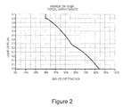
- In these known homogenizers, the relative proportions of gas to liquid in the mixture, i.e. the gas volume fraction (GVF) is directly correlated to the level of the liquid in the reservoir, in that the higher the GVF, the lower the liquid level. This relationship determines the optimum operating envelope of the apparatus. The apparatus can be adapted by choosing appropriate flow areas for respective liquid and gas streams in the outlet, combined with appropriate numbers and sizes of perforations in the pipe. For high GVF applications the liquid outflow rate, and hence the cross-sectional area of the outlet conduit, needs to be small and the perforations in the pipe reduced in size or number or both. However if the liquid flow area is made too small it becomes more prone to blockage from solids. Thus there is a practical limit, dependent upon the size and amount of the solid particles in the flow, below which the liquid flow area cannot be reduced without seriously prejudicing the performance of the apparatus. A typical lower limit in gas and oil applications for a liquid flow clearance is about 5 mm and this equates, using a perforated pipe of around 5 - 30 cm diameter, to a maximum GVF of 90 - 98% corresponding to a maximum GLR of 10 - 50. As a result, it is generally difficult to design the known homogenizing apparatus for optimum operation of GLR above 10 - 50. This is illustrated in
Figure 2 . - Multi-phase mixtures with a very high gas volume fraction (GVF) are known as condensate or "Wet Gas" - a geological term for a gaseous mixture of hydrocarbons that contain a significant amount of compounds with molecular weights heavier than methane. Such wet gas fluids typically have a GVF of above approximately 95% corresponding to a gas liquid ratio (GLR) above 20. Typically such fluids also contain other non-hydrocarbon compounds such as carbon dioxide, hydrogen sulphide, nitrogen, oxygen and water.
- It would be advantageous to provide apparatus which can efficiently handle high GVF multi-fluid flows, such as Wet Gas flows, without being prone to blockage from solid particles in the flow.
- According to one aspect of the present invention there is provided apparatus for homogenization of multi-phase fluid; the fluid comprising at least a first phase and a second phase a gaseous phase and a liquid phase; the apparatus comprising an inner reservoir fluidly communicative with an outer receptacle; the inner reservoir comprising an inlet for multiphase fluid, an outlet having a smaller cross sectional area than the body for outflow of the first phase and at least one opening into the outer receptacle for outflow of the second phase, the opening being spaced from the first phase outlet; wherein the outer receptacle has an outlet conduit having a neck which at least partially surrounds the inner reservoir outlet.
- According to a second aspect of the present invention there is provided a method for homogenizing multi-phase fluid comprising: supplying a multi-phase fluid through an inlet to an inner reservoir which is at least partially surrounded by an outer receptacle; allowing phases of the multi-phase fluid to a least partly separate in the inner reservoir; and drawing off an outlet stream of fluid from the inner reservoir through an outlet comprising a venturi so that fluid is drawn through the outer receptacle into the outlet stream.
- The gas component can be drawn from the gas body through one or more apertures in the roof of the reservoir which communicates with the outer receptacle which may at least partially surround the inner reservoir. An internal partition may also be incorporated.
- Some of the liquid may also be arranged to flow together with the gas from the reservoir into the outer receptacle to the venturi. The amount or proportion of the gas component which is drawn off from the gas body is inversely proportional to the liquid level and thus decreases as a function of an increase of the liquid level, as more of the perforations are submerged. This serves as an automatic regulation of the gas volume fraction.
- The invention is further described below, by way of example, with reference to the accompanying drawings, in which:
-
Figure 1 is a schematic sectional view of one embodiment of a mixing homogenizing apparatus according to the invention; -
Figure 2 graphically illustrates a typical relationship between the liquid level in the apparatus of the prior art and the gas volume fraction (GVF) in the fluid output; -
Figure 3 graphically illustrates the advantage of this invention over the prior art; and -
Figure 4 is a schematic sectional view of a second embodiment of apparatus according to the invention. - The apparatus of
Figure 1 comprises aouter container 10 of generally upright cylindrical form of which the interior is closed, except for the fluid inlets and the outlets to be described. Aninner vessel 20 is located within thecontainer 10 and (in the illustrated embodiment) is coaxial with it. - At the upper region of the cylindrical side wall of the
container 10 andvessel 20, there is aradial inlet port 12 bringing multi-phase fluid at a total flow rate QT (gas & liquid) from a source (not shown) into the interior of theinner vessel 20. Theinlet port 12 may alternatively be axial. Inside thevessel 20 the fluid tends to separate into different phases with liquid collecting in apool 30 which has a depth h, and gas collecting in abody 40 adjacent to and above theliquid pool 30. In this configuration with a cylindrical shaped inner vessel (20) and a radial or axial inlet the separation is caused by gravity. An alternative configuration has a conical shaped inner vessel (20) and a tangential inlet and in that case separation is aided by centrifugal forces creating a cyclonic separation effect in addition to gravity. For both configurations a vertical downward flow through the vessel is the normal orientation with the outlet located at the lower end. However an "upside-down" orientation with the outlet at the upper end is also possible as shown inFigure 4 and described later. - A plurality of
gas outlet ports 21 in theroof 22 of thevessel 20 communicate with theouter container 10 and allow the flow of gas from thegas body 40 in thevessel 20 into the upper part of thecontainer 10 at a flow rate QG. Gas and liquid also flow out into thecontainer 10 through perforations 23 in the side of theinner vessel 20 at respective flow rates QPG and QPL. - The homogenizer comprises a
fluid ejector 27 where liquid and gas are mixed. This comprises aliquid outlet port 15 located centrally in the base of theinner vessel 20 and aneck 25 of an outlet conduit 26 from thecontainer 10. Theneck 25 is normally located slightly downstream of theliquid outlet port 15 but this is not essential. Theliquid outlet port 15 has a diameter DL discharging liquid L at a flow rate QL, into the gas flow QG in theneck 25. Theneck 25 is pinched so that it has a diameter DG, at its narrowest, which is smaller than the diameter DT of the downstream outlet conduit 26. - The preferred ratio DG/DL depends on the application and is chosen to obtain a suitable flow mixer characteristic as explained in more detail in relation to
Figure 2 . - One example of typical dimensions for the
ejector 27 would be that the diameter DG of theneck portion 25 is 150 mm while the diameter of theliquid outlet port 15 is 10 mm so the ratio DG/DL is 15. In general, for oil and gas production applications the diameter DG would be between 20 - 300 mm and the diameter DL between 5 mm and (DG - 10) mm which gives a ratio DG/DL of between 1.03 and 60. Typically a DG/DL ratio of above 2.5 is most appropriate for wet gas (high GVF) applications. - Since the
neck 25 of the outlet conduit 26 is narrower than the outlet conduit 26 a venturi effect is created in theejector 27 where the gas and liquid meet. This causes a higher fluid flow and reduced pressure which forms a turbulent shear layer in the venturi extending downstream and providing an effective means of phase mixing of gas and liquid to form a homogenized multi-phase fluid flowing out of the outlet conduit 26 at a flow rate QT. - Different downstream devices such as a multiphase pump or a multiphase flow meter benefit from the mixing process because a well mixed flow is normally required in order to achieve optimum performance of multiphase devices. For example, even a pipe arrangement for splitting a multiphase stream in two or more equal streams is very unlikely to work properly unless the upstream flow is well mixed.
- If the multi-phase fluid entering the apparatus is already homogenous or approximately so, then the fluid mixture will be discharged through the outlet conduit 26 by way of both the inner
vessel outlet port 15 and the outer container outlet 26. - The production flow is driven by a reservoir pressure higher than a downstream pressure.
- The objective of the sampling ports are to collect respectively liquid rich and gas rich fluid samples. The fluid samples are sampled carefully into a sampling bottle maintaining the process pressure and temperature. Normally the sampling operation will be carried out by use of an ROV (Remotely Operated Vessel) and the bottles (one with the liquid rich fluid and one with the gas rich fluid) will be brought to the surface and further to a laboratory where the fluids are analysed for their constituents and properties, particularly the water-oil ratio or water cut of the liquid phase.
- This is particular useful when several well streams are combined subsea and routed to topside via a single pipeline. A topside sample will then only be representative for total combined flow and not be able to provide information from the individual well fluids. A subsea sampling unit located upstream the manifold will on the contrary be able to provide representative fluid samples from individual wells.
- In combination with multiphase flow meters it might be particular useful to obtain the salt content of the water but also other fluid constituents such as sulphur etc. which influence the calibration coefficients of the flow meter.
- Accurate multiphase flow measurements depends on a very precise description of the respective oil, water and gas phase properties. Normally phase densities, mass attenuation and/or electrical properties of the individual phases are required, and these properties will be influenced by different constituents such as the salt content of the water and sulphur content of the oil. Wet gas measurements will in particular also be sensitive to the gas properties.
- As a supplement or in some cases alternative to a multiphase flow meter a subsea sampling device can be used to detect water break through and obtain the water cut particular at wet gas conditions where accurate measures are difficult to obtain from multiphase flow meters.
- In some cases subsea sampling might be used stand-alone to detect chemical tracers identifying active production zones or simply to obtain fluid properties (other than flow rates) to better describe the reservoir and its fluid.
- A subsea sampling process involves a lot of equipment, resources and cost. Due to the chaotic and non-predictability of a multiphase stream the risk of failing to obtain a representative sample of the different fluid phases has normally been high due to the lack of adequate sampling devices.
- A
sampling outlet 50 controlled byvalve 60 is provided for sampling the gas rich stream SG of fluid in the outer container. For sampling the liquid rich stream SL in thepool 30 inside thevessel 20, asampling outlet 51 is provided controlled byvalve 61. Sampling the respective phases of the fluid in this way allows the process to be closely monitored and enables better and more accurate control. For example, flow can be adjusted for optimum performance for particular conditions. -
Figure 4 shows another embodiment of the invention in which the apparatus is essentially "upside-down". Equivalent features are prefaced with "4" for ease of reference. - Thus
outer container 410 has aninner vessel 420,inlet port 412 for the multiphase fluid andfluid ejector 427 where the liquid and gas phases are mixed. The multiphase fluid separates into different phases, as in the first embodiment of theFigure 1 , with liquid collecting in apool 430 to a depth h, and gas in abody 440 above theliquid pool 430. In thisembodiment outlet ports 421 are in the base ofvessel 420 and allow liquid to flow from thepool 430 into thecontainer 410 at a flow rate QL.Perforations 423 in the side of theinner vessel 420 allows gas and liquid to flow out of theinner vessel 420. - The
ejector 427 comprisesinner outlet port 415 into theneck 425 of thecontainer 410. It will be seen that the gas and liquid streams are essentially reversed in this embodiment in that gas flows predominantly from theinner vessel 420 through theinner outlet port 415 whereas liquid flows out ofports 421 andperforations 423 and through theejector 427 via theneck 425. -
Liquid sampling outlet 451 controlled byvalve 461 exits from theouter container 410 in this embodiment andgas sampling outlet 450 controlled byvalve 460 exits from theinner vessel 420. - The present invention has the effect of enabling a homogenizer to be designed for a relatively high gas volume fraction (GVF) by designing the unit with a small liquid to gas area ratio in the outlet without compromising the requirements for a minimum clearance in the liquid stream path to avoid blockage by particles.
- For the purpose of demonstrating the added benefit of the present invention compared to known homogenizers, the relative amount of the volumetric gas flow rate will be expressed through the Gas Liquid Ratio (GLR) instead of the Gas Volume Fractions (GVF). The two terms are however related as described by the equation below. In the following it should be noted that the diameters DG and DL are taken in the same plane.

- For the prior art homogenizer described in
EP 0 379 319
- Where L and G are geometric parameters, F is a flow parameter and ρL and ρG are the liquid and gas phase densities respectively. The flow parameter F is expressed as:

- By introducing the liquid to gas area ratio AR in the
ejector 27 defined as:
where AL and AG are the respective liquid and gas flow areas in the ejector and making a few minor assumptions such as neglecting frictional losses it is possible to a derive an approximate expression for the outlet GVF or outlet GLR for a homogenizer without perforations as follows:
- The effect of the perforations 23 is not described here as any perforations will tend to reduce the outlet GLR while the present invention aims to increase the outlet GLR. However the function of any perforations will be similar for the present invention as it is for the known homogenizers.
- The relation for the outlet GLR as expressed by equation 5 is valid both for the present invention as well as for the known homogenizer. However the liquid to gas area ratio will be expressed differently as described below.
- In known mixers, assuming that the wall of the
central vessel 20 is relatively thin, and for high GLR applications the annulus clearance is small, then the hydraulic mean diameter of the annulus in theejector 27 is close to the internal diameter of thecentral vessel 20, thus:
- For the present invention the diameter of the liquid flow area DL in the
ejector 27 will be named clearance (C), in order to show the relationship with the known homogenizer. Further, assuming that for high GLR applications the DL or C will be much smaller than the diameter of the gas flow area such that the area occupied by the liquid can be neglected when the gas flow area is calculated, thus:
- Comparing the liquid to gas area ratio AR of the present invention to that of the prior art we can write:

- From equation 8 it will be observed that for typical dimensions the outlet GLR of the present invention can be increased in the order of up to 100 times compared with that of the known homogenizers.
- The typical maximum outlet GLR that can be obtained with the present invention and compared with the prior art is shown in
Figure 3 , assuming a liquid level of 0.5 m and a gas velocity of 12 m/s. For higher liquid levels the negative gradient of the characteristic curve can be reduced by introducing perforations if required to increase the GLR range of the apparatus. - It will be readily appreciated that the invention can be embodied in a variety of ways other than as specifically described and illustrated.
Claims (22)
- Apparatus for homogenization of multi-phase fluid;
the fluid comprising at least a first phase and a second phase comprising a gaseous phase and a liquid phase;
the apparatus comprising an inner reservoir (20) fluidly communicative with an outer receptacle (10);
the inner reservoir (20) comprising an inlet (12) for multiphase fluid, an outlet (15) having a smaller cross sectional area than the body for outflow of the first phase and at least one opening into the outer receptacle for outflow of the second phase, the opening being spaced from the first phase outlet;
wherein the outer receptacle (10) has an outlet conduit (26) having a neck (25) which at least partially surrounds the inner reservoir outlet (15). - Apparatus according to claim 1 wherein the inner reservoir (20) comprises a conical shaped vessel (20).
- Apparatus according to claim 1 or 2 wherein the outlet (15) and the conduit (26) are at the bottom of the apparatus in use, and wherein the first phase is a liquid phase and the second phase is a gaseous phase.
- Apparatus according to claim 1 or 2 wherein the outlet (15) and the conduit (26) are at the top of the apparatus in use, and wherein the first phase is a gaseous phase and the second phase is a liquid phase.
- Apparatus according to claim 2, 3 or 4 wherein the multi-phase fluid inlet (12) in the inner reservoir (20) is orientated radially with respect to the conical shaped vessel (20).
- Apparatus according to any one of the preceding claims wherein the multi-phase fluid inlet (12) is spaced from the inner reservoir outlet (15).
- Apparatus according to any one of the preceding claims wherein the ratio of the diameter (DG) of the neck (25) to the diameter (DL) of the inner reservoir outlet (15) is above 2.5.
- Apparatus according to claim 7 wherein the ratio (DG/DL) is between 5 and 60.
- Apparatus according to claim 8 wherein the ratio (DG/DL) is between 10 and 30.
- Apparatus according to claim 9 wherein the ratio (DG/DL) is about 15.
- Apparatus according to any preceding claim wherein the inner reservoir (20) comprises a plurality of openings (21, 23) for fluid to pass from the inner reservoir (20) into the outer receptacle (10).
- Apparatus according to claim 11 wherein at least one opening (21) is at an end of the inner reservoir (20) opposite to the inner reservoir outlet (15).
- Apparatus according to claim 11 or 12 wherein at least one opening (23) is in the side of the inner reservoir (20) between the ends of the inner reservoir (20).
- Apparatus according to claim 13 comprising a plurality of openings (23) in the side of the inner reservoir (20).
- Apparatus according to any one of the preceding claims wherein the neck comprises a venturi (25) in the outlet (27).
- Apparatus according to any one of the preceding claims comprising means to sample fluid in the outer receptacle (10).
- Apparatus according to any one of the preceding claims comprising means to sample fluid in the inner reservoir (20).
- A method for homogenizing multi-phase fluid comprising:supplying a multi-phase fluid through an inlet (12) to an inner reservoir (20) which is at least partially surrounded by an outer receptacle (10);allowing phases of the multi-phase fluid to a least partly separate in the inner reservoir (20); anddrawing off an outlet stream of fluid from the inner reservoir (20) through an outlet (15) comprising a venturi so that fluid is drawn through the outer receptacle into the outlet stream.
- A method according to claim 18 wherein the inner reservoir (20) comprises a conical shaped vessel and the multi-phase fluid is supplied through the inlet (12) radially orientated with respect to the reservoir (20).
- A method according to claim 18 or 19 wherein the ratio of the outer receptacle outlet (27) to the outlet (15) of the inner reservoir (20) is arranged to be between 10 and 30.
- A method according to claim 18, 19 or 20 comprising sampling fluid in the outer receptacle.
- A method according to claim 18, 19, 20 or 21 comprising sampling fluid in the inner reservoir (20).
Applications Claiming Priority (1)
| Application Number | Priority Date | Filing Date | Title |
|---|---|---|---|
| GB1014765.0A GB2483438A (en) | 2010-09-06 | 2010-09-06 | Homogenising a multiphase fluid |
Publications (2)
| Publication Number | Publication Date |
|---|---|
| EP2425890A1 true EP2425890A1 (en) | 2012-03-07 |
| EP2425890B1 EP2425890B1 (en) | 2013-09-04 |
Family
ID=43037362
Family Applications (1)
| Application Number | Title | Priority Date | Filing Date |
|---|---|---|---|
| EP11180104.9A Active EP2425890B1 (en) | 2010-09-06 | 2011-09-05 | Flow Conditioning Apparatus |
Country Status (6)
| Country | Link |
|---|---|
| US (1) | US8777476B2 (en) |
| EP (1) | EP2425890B1 (en) |
| CN (1) | CN102430354B (en) |
| AU (1) | AU2011218628B2 (en) |
| BR (1) | BRPI1104642A2 (en) |
| GB (1) | GB2483438A (en) |
Cited By (2)
| Publication number | Priority date | Publication date | Assignee | Title |
|---|---|---|---|---|
| NO337168B1 (en) * | 2012-07-05 | 2016-02-01 | Fmc Kongsberg Subsea As | Apparatus and method for mixing at least a first and second fluid phases |
| US9463424B2 (en) | 2014-07-09 | 2016-10-11 | Onesubsea Ip Uk Limited | Actuatable flow conditioning apparatus |
Families Citing this family (2)
| Publication number | Priority date | Publication date | Assignee | Title |
|---|---|---|---|---|
| US12678750B2 (en) * | 2022-11-14 | 2026-07-14 | Dean Lee Millar | Measure to improve liquid-gas eductor performance |
| JP2024084283A (en) * | 2022-12-13 | 2024-06-25 | Cpmホールディング株式会社 | A liquefaction promotion device that uses fluid agitation to be installed in the piping of a heat pump system |
Citations (4)
| Publication number | Priority date | Publication date | Assignee | Title |
|---|---|---|---|---|
| EP0379319A2 (en) | 1989-01-16 | 1990-07-25 | Framo Developments (U.K.) Limited | Fluid homogenization |
| WO1990013859A1 (en) | 1989-05-05 | 1990-11-15 | Framo Developments (Uk) Limited | Multiphase process mixing and measuring system |
| DE4224911A1 (en) * | 1992-07-09 | 1994-01-13 | Tech Resources Pty Ltd | Aerator, esp. for provision of oxygen@ to biological ore extn. liq. - contains of vertical duct with throat section which has elongated shape and is provided with means for introducing required gas |
| WO2008061972A1 (en) * | 2006-11-22 | 2008-05-29 | Shell Internationale Research Maatschappij B.V. | Method and apparatus for providing uniformity of vapour and liquid phases in a mixed stream |
Family Cites Families (11)
| Publication number | Priority date | Publication date | Assignee | Title |
|---|---|---|---|---|
| DE2731279C2 (en) * | 1977-07-11 | 1986-07-17 | KÜBA Kühlerfabrik Heinrich W. Schmitz GmbH, 8021 Baierbrunn | Device for distributing a flowing liquid-gas mixture into several partial flows |
| US4426880A (en) * | 1981-07-24 | 1984-01-24 | Phillips Petroleum Company | Method and apparatus for fluid sampling and testing |
| US4597950A (en) * | 1983-05-05 | 1986-07-01 | Bechtel International Corporation | Gas separating-crystallizer |
| FR2610105A1 (en) * | 1987-01-26 | 1988-07-29 | Elf Aquitaine | METHOD AND DIPHASIC SEPARATOR-METER FOR MEASURING, CONTINUOUSLY AND RESPECTIVELY, THE QUANTITIES OF GAS AND LIQUID DELIVERED IN A DYNAMIC FLOW OF A MIXTURE OF GAS AND LIQUID |
| US5254292A (en) * | 1989-02-02 | 1993-10-19 | Institut Francais Du Petrole | Device for regulating and reducing the fluctuations in a polyphasic flow, and its use |
| FR2669556B1 (en) * | 1990-11-27 | 1993-01-15 | Inst Francais Du Petrole | DEVICE FOR AGITATING AND SUSPENDING THE PARTICLES OF A POLYPHASTIC FLOW. |
| DK0549440T3 (en) * | 1991-12-27 | 1997-03-24 | Inst Francais Du Petrole | Process for optimizing a device for controlling and attenuating a multi-phase flow and device obtained by the method |
| FR2688147B1 (en) * | 1992-03-09 | 1994-09-23 | Technicatome | DEVICE FOR RESORBING GAS CAPS IN A TWO - PHASE FLOW. |
| DE10250406B4 (en) * | 2001-10-30 | 2007-10-25 | Hitachi, Ltd. | Reaction device and mixing system |
| TWI251857B (en) * | 2004-03-09 | 2006-03-21 | Tokyo Electron Ltd | Two-fluid nozzle for cleaning substrate and substrate cleaning device |
| MX2007001701A (en) * | 2004-08-11 | 2007-04-12 | Better Power Llc A | Hydraulic liquid pumping system. |
-
2010
- 2010-09-06 GB GB1014765.0A patent/GB2483438A/en not_active Withdrawn
-
2011
- 2011-08-29 AU AU2011218628A patent/AU2011218628B2/en not_active Ceased
- 2011-09-05 BR BRPI1104642-2A patent/BRPI1104642A2/en not_active IP Right Cessation
- 2011-09-05 EP EP11180104.9A patent/EP2425890B1/en active Active
- 2011-09-06 US US13/225,610 patent/US8777476B2/en not_active Expired - Fee Related
- 2011-09-06 CN CN201110270263.0A patent/CN102430354B/en not_active Expired - Fee Related
Patent Citations (4)
| Publication number | Priority date | Publication date | Assignee | Title |
|---|---|---|---|---|
| EP0379319A2 (en) | 1989-01-16 | 1990-07-25 | Framo Developments (U.K.) Limited | Fluid homogenization |
| WO1990013859A1 (en) | 1989-05-05 | 1990-11-15 | Framo Developments (Uk) Limited | Multiphase process mixing and measuring system |
| DE4224911A1 (en) * | 1992-07-09 | 1994-01-13 | Tech Resources Pty Ltd | Aerator, esp. for provision of oxygen@ to biological ore extn. liq. - contains of vertical duct with throat section which has elongated shape and is provided with means for introducing required gas |
| WO2008061972A1 (en) * | 2006-11-22 | 2008-05-29 | Shell Internationale Research Maatschappij B.V. | Method and apparatus for providing uniformity of vapour and liquid phases in a mixed stream |
Cited By (3)
| Publication number | Priority date | Publication date | Assignee | Title |
|---|---|---|---|---|
| NO337168B1 (en) * | 2012-07-05 | 2016-02-01 | Fmc Kongsberg Subsea As | Apparatus and method for mixing at least a first and second fluid phases |
| US11241662B2 (en) | 2012-07-05 | 2022-02-08 | FMG Kongsberg Subsea AS | Multiphase flow mixing apparatus and method of mixing |
| US9463424B2 (en) | 2014-07-09 | 2016-10-11 | Onesubsea Ip Uk Limited | Actuatable flow conditioning apparatus |
Also Published As
| Publication number | Publication date |
|---|---|
| US20120057427A1 (en) | 2012-03-08 |
| AU2011218628A1 (en) | 2012-03-22 |
| GB201014765D0 (en) | 2010-10-20 |
| AU2011218628B2 (en) | 2015-05-07 |
| CN102430354B (en) | 2016-10-05 |
| CN102430354A (en) | 2012-05-02 |
| BRPI1104642A2 (en) | 2013-01-22 |
| GB2483438A (en) | 2012-03-14 |
| US8777476B2 (en) | 2014-07-15 |
| EP2425890B1 (en) | 2013-09-04 |
Similar Documents
| Publication | Publication Date | Title |
|---|---|---|
| RU2093257C1 (en) | Device for mixing or homogenization of liquid and fluid medium and method of mixing or homogenization of liquid and fluid medium | |
| US5390547A (en) | Multiphase flow separation and measurement system | |
| US12559389B2 (en) | Bubble size monitoring and control | |
| CN1246567C (en) | Systems for the production of dehydrated oils | |
| US20090065431A1 (en) | In-line separator | |
| CA2965595C (en) | A method and apparatus for the isokinetic sampling of a multiphase stream | |
| EP2546617A1 (en) | Batch-type multiphase flow measurement device and flow measurement method | |
| EP2969125A1 (en) | Apparatus and method for gas-liquid separation | |
| US8555708B2 (en) | Robust system and method for obtaining a liquid or gas sample from a multiphase mixture flowing in a hydrocarbon pipeline | |
| US20180313213A1 (en) | System and methodology for chemical constituent sensing and analysis | |
| EP2425890B1 (en) | Flow Conditioning Apparatus | |
| US20100108314A1 (en) | System and method for downhole sampling or sensing of clean samples of component fluids of a multi-fluid mixture | |
| JP2018533463A5 (en) | ||
| EP0379319A2 (en) | Fluid homogenization | |
| EP3302775B1 (en) | Apparatus for mixing of fluids flowing through a conduit | |
| EP1899685B1 (en) | Method and device for determining the density of one of the components of a multi-component fluid flow | |
| US20190224593A1 (en) | Separation vessel with enhanced particulate removal | |
| EA009424B1 (en) | Separator for cyclonic separation of gaseous and liquid fractions | |
| WO2011057783A1 (en) | Process for the separation of a multiphase stream which flows along a pipe by means of a t-junction | |
| CN113692311A (en) | Apparatus and method for gas-liquid separation of multiphase fluids | |
| EP2145676A1 (en) | Device and method for homogenizing fluids | |
| US7017663B2 (en) | System for producing de-watered oil | |
| RU2382813C1 (en) | Reagent dosing method and equipment for implementation | |
| MXPA97010333A (en) | Separator of high efficiency mixtures | |
| Odozi et al. | Three phase air-oil-water flow patterns |
Legal Events
| Date | Code | Title | Description |
|---|---|---|---|
| AK | Designated contracting states |
Kind code of ref document: A1 Designated state(s): AL AT BE BG CH CY CZ DE DK EE ES FI FR GB GR HR HU IE IS IT LI LT LU LV MC MK MT NL NO PL PT RO RS SE SI SK SM TR |
|
| AX | Request for extension of the european patent |
Extension state: BA ME |
|
| PUAI | Public reference made under article 153(3) epc to a published international application that has entered the european phase |
Free format text: ORIGINAL CODE: 0009012 |
|
| 17P | Request for examination filed |
Effective date: 20120907 |
|
| GRAP | Despatch of communication of intention to grant a patent |
Free format text: ORIGINAL CODE: EPIDOSNIGR1 |
|
| GRAS | Grant fee paid |
Free format text: ORIGINAL CODE: EPIDOSNIGR3 |
|
| GRAA | (expected) grant |
Free format text: ORIGINAL CODE: 0009210 |
|
| AK | Designated contracting states |
Kind code of ref document: B1 Designated state(s): AL AT BE BG CH CY CZ DE DK EE ES FI FR GB GR HR HU IE IS IT LI LT LU LV MC MK MT NL NO PL PT RO RS SE SI SK SM TR |
|
| REG | Reference to a national code |
Ref country code: GB Ref legal event code: FG4D |
|
| REG | Reference to a national code |
Ref country code: CH Ref legal event code: EP |
|
| REG | Reference to a national code |
Ref country code: AT Ref legal event code: REF Ref document number: 630172 Country of ref document: AT Kind code of ref document: T Effective date: 20130915 |
|
| REG | Reference to a national code |
Ref country code: IE Ref legal event code: FG4D |
|
| REG | Reference to a national code |
Ref country code: DE Ref legal event code: R096 Ref document number: 602011002897 Country of ref document: DE Effective date: 20131031 |
|
| REG | Reference to a national code |
Ref country code: AT Ref legal event code: MK05 Ref document number: 630172 Country of ref document: AT Kind code of ref document: T Effective date: 20130904 |
|
| REG | Reference to a national code |
Ref country code: NO Ref legal event code: T2 Effective date: 20130904 |
|
| REG | Reference to a national code |
Ref country code: NL Ref legal event code: VDEP Effective date: 20130904 |
|
| PG25 | Lapsed in a contracting state [announced via postgrant information from national office to epo] |
Ref country code: LT Free format text: LAPSE BECAUSE OF FAILURE TO SUBMIT A TRANSLATION OF THE DESCRIPTION OR TO PAY THE FEE WITHIN THE PRESCRIBED TIME-LIMIT Effective date: 20130904 Ref country code: AT Free format text: LAPSE BECAUSE OF FAILURE TO SUBMIT A TRANSLATION OF THE DESCRIPTION OR TO PAY THE FEE WITHIN THE PRESCRIBED TIME-LIMIT Effective date: 20130904 Ref country code: CY Free format text: LAPSE BECAUSE OF FAILURE TO SUBMIT A TRANSLATION OF THE DESCRIPTION OR TO PAY THE FEE WITHIN THE PRESCRIBED TIME-LIMIT Effective date: 20130814 Ref country code: SE Free format text: LAPSE BECAUSE OF FAILURE TO SUBMIT A TRANSLATION OF THE DESCRIPTION OR TO PAY THE FEE WITHIN THE PRESCRIBED TIME-LIMIT Effective date: 20130904 Ref country code: HR Free format text: LAPSE BECAUSE OF FAILURE TO SUBMIT A TRANSLATION OF THE DESCRIPTION OR TO PAY THE FEE WITHIN THE PRESCRIBED TIME-LIMIT Effective date: 20130904 |
|
| REG | Reference to a national code |
Ref country code: NL Ref legal event code: VDEP Effective date: 20130904 |
|
| REG | Reference to a national code |
Ref country code: LT Ref legal event code: MG4D |
|
| PG25 | Lapsed in a contracting state [announced via postgrant information from national office to epo] |
Ref country code: SI Free format text: LAPSE BECAUSE OF FAILURE TO SUBMIT A TRANSLATION OF THE DESCRIPTION OR TO PAY THE FEE WITHIN THE PRESCRIBED TIME-LIMIT Effective date: 20130904 Ref country code: LV Free format text: LAPSE BECAUSE OF FAILURE TO SUBMIT A TRANSLATION OF THE DESCRIPTION OR TO PAY THE FEE WITHIN THE PRESCRIBED TIME-LIMIT Effective date: 20130904 Ref country code: FI Free format text: LAPSE BECAUSE OF FAILURE TO SUBMIT A TRANSLATION OF THE DESCRIPTION OR TO PAY THE FEE WITHIN THE PRESCRIBED TIME-LIMIT Effective date: 20130904 Ref country code: PL Free format text: LAPSE BECAUSE OF FAILURE TO SUBMIT A TRANSLATION OF THE DESCRIPTION OR TO PAY THE FEE WITHIN THE PRESCRIBED TIME-LIMIT Effective date: 20130904 Ref country code: GR Free format text: LAPSE BECAUSE OF FAILURE TO SUBMIT A TRANSLATION OF THE DESCRIPTION OR TO PAY THE FEE WITHIN THE PRESCRIBED TIME-LIMIT Effective date: 20131205 |
|
| PG25 | Lapsed in a contracting state [announced via postgrant information from national office to epo] |
Ref country code: CY Free format text: LAPSE BECAUSE OF FAILURE TO SUBMIT A TRANSLATION OF THE DESCRIPTION OR TO PAY THE FEE WITHIN THE PRESCRIBED TIME-LIMIT Effective date: 20130904 Ref country code: BE Free format text: LAPSE BECAUSE OF FAILURE TO SUBMIT A TRANSLATION OF THE DESCRIPTION OR TO PAY THE FEE WITHIN THE PRESCRIBED TIME-LIMIT Effective date: 20130904 |
|
| PG25 | Lapsed in a contracting state [announced via postgrant information from national office to epo] |
Ref country code: SK Free format text: LAPSE BECAUSE OF FAILURE TO SUBMIT A TRANSLATION OF THE DESCRIPTION OR TO PAY THE FEE WITHIN THE PRESCRIBED TIME-LIMIT Effective date: 20130904 Ref country code: NL Free format text: LAPSE BECAUSE OF FAILURE TO SUBMIT A TRANSLATION OF THE DESCRIPTION OR TO PAY THE FEE WITHIN THE PRESCRIBED TIME-LIMIT Effective date: 20130904 Ref country code: EE Free format text: LAPSE BECAUSE OF FAILURE TO SUBMIT A TRANSLATION OF THE DESCRIPTION OR TO PAY THE FEE WITHIN THE PRESCRIBED TIME-LIMIT Effective date: 20130904 Ref country code: CZ Free format text: LAPSE BECAUSE OF FAILURE TO SUBMIT A TRANSLATION OF THE DESCRIPTION OR TO PAY THE FEE WITHIN THE PRESCRIBED TIME-LIMIT Effective date: 20130904 Ref country code: IS Free format text: LAPSE BECAUSE OF FAILURE TO SUBMIT A TRANSLATION OF THE DESCRIPTION OR TO PAY THE FEE WITHIN THE PRESCRIBED TIME-LIMIT Effective date: 20140104 Ref country code: RO Free format text: LAPSE BECAUSE OF FAILURE TO SUBMIT A TRANSLATION OF THE DESCRIPTION OR TO PAY THE FEE WITHIN THE PRESCRIBED TIME-LIMIT Effective date: 20130904 |
|
| PG25 | Lapsed in a contracting state [announced via postgrant information from national office to epo] |
Ref country code: ES Free format text: LAPSE BECAUSE OF FAILURE TO SUBMIT A TRANSLATION OF THE DESCRIPTION OR TO PAY THE FEE WITHIN THE PRESCRIBED TIME-LIMIT Effective date: 20130904 |
|
| REG | Reference to a national code |
Ref country code: DE Ref legal event code: R119 Ref document number: 602011002897 Country of ref document: DE Effective date: 20140401 |
|
| PG25 | Lapsed in a contracting state [announced via postgrant information from national office to epo] |
Ref country code: MC Free format text: LAPSE BECAUSE OF FAILURE TO SUBMIT A TRANSLATION OF THE DESCRIPTION OR TO PAY THE FEE WITHIN THE PRESCRIBED TIME-LIMIT Effective date: 20130904 Ref country code: PT Free format text: LAPSE BECAUSE OF FAILURE TO SUBMIT A TRANSLATION OF THE DESCRIPTION OR TO PAY THE FEE WITHIN THE PRESCRIBED TIME-LIMIT Effective date: 20140106 |
|
| REG | Reference to a national code |
Ref country code: IE Ref legal event code: MM4A |
|
| PLBE | No opposition filed within time limit |
Free format text: ORIGINAL CODE: 0009261 |
|
| STAA | Information on the status of an ep patent application or granted ep patent |
Free format text: STATUS: NO OPPOSITION FILED WITHIN TIME LIMIT |
|
| PG25 | Lapsed in a contracting state [announced via postgrant information from national office to epo] |
Ref country code: IE Free format text: LAPSE BECAUSE OF NON-PAYMENT OF DUE FEES Effective date: 20130905 |
|
| 26N | No opposition filed |
Effective date: 20140605 |
|
| PG25 | Lapsed in a contracting state [announced via postgrant information from national office to epo] |
Ref country code: IT Free format text: LAPSE BECAUSE OF FAILURE TO SUBMIT A TRANSLATION OF THE DESCRIPTION OR TO PAY THE FEE WITHIN THE PRESCRIBED TIME-LIMIT Effective date: 20130904 Ref country code: DE Free format text: LAPSE BECAUSE OF NON-PAYMENT OF DUE FEES Effective date: 20140401 |
|
| PG25 | Lapsed in a contracting state [announced via postgrant information from national office to epo] |
Ref country code: DK Free format text: LAPSE BECAUSE OF FAILURE TO SUBMIT A TRANSLATION OF THE DESCRIPTION OR TO PAY THE FEE WITHIN THE PRESCRIBED TIME-LIMIT Effective date: 20130904 |
|
| REG | Reference to a national code |
Ref country code: CH Ref legal event code: PL |
|
| PG25 | Lapsed in a contracting state [announced via postgrant information from national office to epo] |
Ref country code: SM Free format text: LAPSE BECAUSE OF FAILURE TO SUBMIT A TRANSLATION OF THE DESCRIPTION OR TO PAY THE FEE WITHIN THE PRESCRIBED TIME-LIMIT Effective date: 20130904 |
|
| PG25 | Lapsed in a contracting state [announced via postgrant information from national office to epo] |
Ref country code: MT Free format text: LAPSE BECAUSE OF FAILURE TO SUBMIT A TRANSLATION OF THE DESCRIPTION OR TO PAY THE FEE WITHIN THE PRESCRIBED TIME-LIMIT Effective date: 20130904 Ref country code: TR Free format text: LAPSE BECAUSE OF FAILURE TO SUBMIT A TRANSLATION OF THE DESCRIPTION OR TO PAY THE FEE WITHIN THE PRESCRIBED TIME-LIMIT Effective date: 20130904 |
|
| PG25 | Lapsed in a contracting state [announced via postgrant information from national office to epo] |
Ref country code: RS Free format text: LAPSE BECAUSE OF FAILURE TO SUBMIT A TRANSLATION OF THE DESCRIPTION OR TO PAY THE FEE WITHIN THE PRESCRIBED TIME-LIMIT Effective date: 20131204 Ref country code: MK Free format text: LAPSE BECAUSE OF FAILURE TO SUBMIT A TRANSLATION OF THE DESCRIPTION OR TO PAY THE FEE WITHIN THE PRESCRIBED TIME-LIMIT Effective date: 20130904 Ref country code: CH Free format text: LAPSE BECAUSE OF NON-PAYMENT OF DUE FEES Effective date: 20140930 Ref country code: BG Free format text: LAPSE BECAUSE OF FAILURE TO SUBMIT A TRANSLATION OF THE DESCRIPTION OR TO PAY THE FEE WITHIN THE PRESCRIBED TIME-LIMIT Effective date: 20130904 Ref country code: LI Free format text: LAPSE BECAUSE OF NON-PAYMENT OF DUE FEES Effective date: 20140930 Ref country code: LU Free format text: LAPSE BECAUSE OF NON-PAYMENT OF DUE FEES Effective date: 20130905 Ref country code: HU Free format text: LAPSE BECAUSE OF FAILURE TO SUBMIT A TRANSLATION OF THE DESCRIPTION OR TO PAY THE FEE WITHIN THE PRESCRIBED TIME-LIMIT; INVALID AB INITIO Effective date: 20110905 |
|
| REG | Reference to a national code |
Ref country code: FR Ref legal event code: PLFP Year of fee payment: 6 |
|
| REG | Reference to a national code |
Ref country code: FR Ref legal event code: PLFP Year of fee payment: 7 |
|
| PGFP | Annual fee paid to national office [announced via postgrant information from national office to epo] |
Ref country code: FR Payment date: 20170928 Year of fee payment: 7 |
|
| PG25 | Lapsed in a contracting state [announced via postgrant information from national office to epo] |
Ref country code: AL Free format text: LAPSE BECAUSE OF FAILURE TO SUBMIT A TRANSLATION OF THE DESCRIPTION OR TO PAY THE FEE WITHIN THE PRESCRIBED TIME-LIMIT Effective date: 20130904 |
|
| PG25 | Lapsed in a contracting state [announced via postgrant information from national office to epo] |
Ref country code: FR Free format text: LAPSE BECAUSE OF NON-PAYMENT OF DUE FEES Effective date: 20180930 |
|
| PGFP | Annual fee paid to national office [announced via postgrant information from national office to epo] |
Ref country code: NO Payment date: 20250909 Year of fee payment: 15 |
|
| PGFP | Annual fee paid to national office [announced via postgrant information from national office to epo] |
Ref country code: GB Payment date: 20250703 Year of fee payment: 15 |