EP2424466B1 - Apparatus for silicone breast implant delivery - Google Patents
Apparatus for silicone breast implant delivery Download PDFInfo
- Publication number
- EP2424466B1 EP2424466B1 EP09844125.6A EP09844125A EP2424466B1 EP 2424466 B1 EP2424466 B1 EP 2424466B1 EP 09844125 A EP09844125 A EP 09844125A EP 2424466 B1 EP2424466 B1 EP 2424466B1
- Authority
- EP
- European Patent Office
- Prior art keywords
- sleeve
- implant
- prosthesis
- distal opening
- opening
- Prior art date
- Legal status (The legal status is an assumption and is not a legal conclusion. Google has not performed a legal analysis and makes no representation as to the accuracy of the status listed.)
- Revoked
Links
Images




Classifications
-
- A—HUMAN NECESSITIES
- A61—MEDICAL OR VETERINARY SCIENCE; HYGIENE
- A61F—FILTERS IMPLANTABLE INTO BLOOD VESSELS; PROSTHESES; DEVICES PROVIDING PATENCY TO, OR PREVENTING COLLAPSING OF, TUBULAR STRUCTURES OF THE BODY, e.g. STENTS; ORTHOPAEDIC, NURSING OR CONTRACEPTIVE DEVICES; FOMENTATION; TREATMENT OR PROTECTION OF EYES OR EARS; BANDAGES, DRESSINGS OR ABSORBENT PADS; FIRST-AID KITS
- A61F2/00—Filters implantable into blood vessels; Prostheses, i.e. artificial substitutes or replacements for parts of the body; Appliances for connecting them with the body; Devices providing patency to, or preventing collapsing of, tubular structures of the body, e.g. stents
- A61F2/02—Prostheses implantable into the body
- A61F2/12—Mammary prostheses
-
- A—HUMAN NECESSITIES
- A61—MEDICAL OR VETERINARY SCIENCE; HYGIENE
- A61F—FILTERS IMPLANTABLE INTO BLOOD VESSELS; PROSTHESES; DEVICES PROVIDING PATENCY TO, OR PREVENTING COLLAPSING OF, TUBULAR STRUCTURES OF THE BODY, e.g. STENTS; ORTHOPAEDIC, NURSING OR CONTRACEPTIVE DEVICES; FOMENTATION; TREATMENT OR PROTECTION OF EYES OR EARS; BANDAGES, DRESSINGS OR ABSORBENT PADS; FIRST-AID KITS
- A61F2230/00—Geometry of prostheses classified in groups A61F2/00 - A61F2/26 or A61F2/82 or A61F9/00 or A61F11/00 or subgroups thereof
- A61F2230/0063—Three-dimensional shapes
- A61F2230/0067—Three-dimensional shapes conical
-
- A—HUMAN NECESSITIES
- A61—MEDICAL OR VETERINARY SCIENCE; HYGIENE
- A61F—FILTERS IMPLANTABLE INTO BLOOD VESSELS; PROSTHESES; DEVICES PROVIDING PATENCY TO, OR PREVENTING COLLAPSING OF, TUBULAR STRUCTURES OF THE BODY, e.g. STENTS; ORTHOPAEDIC, NURSING OR CONTRACEPTIVE DEVICES; FOMENTATION; TREATMENT OR PROTECTION OF EYES OR EARS; BANDAGES, DRESSINGS OR ABSORBENT PADS; FIRST-AID KITS
- A61F2250/00—Special features of prostheses classified in groups A61F2/00 - A61F2/26 or A61F2/82 or A61F9/00 or A61F11/00 or subgroups thereof
- A61F2250/0058—Additional features; Implant or prostheses properties not otherwise provided for
- A61F2250/0096—Markers and sensors for detecting a position or changes of a position of an implant, e.g. RF sensors, ultrasound markers
- A61F2250/0097—Visible markings, e.g. indicia
Definitions
- the present invention relates to an apparatus for manually delivering a pre-filled breast implant into a surgical pocket.
- Silicone breast implants were re-approved in the United States in November 2006 after having been withdrawn from the market. Implant recipients cite safety, scarring, and "natural" look and feel to be the top three indicators in selecting between saline- and silicone-filled implants for breast augmentation. Given that the more natural look and feel offered by silicon is a pre-requisite for many patients, silicone implants have already achieved nearly 50% market share following their return to the market.
- silicone implants are pre-filled (to alleviate leakage concerns) they have generally required larger access incisions than saline implants. Due to the possibility of visible scars associated with the larger incisions, some patients have remained apprehensive about selecting silicone implants.
- the Keller filing describes a device and methods addressing each of the above-referenced issues. It discloses a specially-adapted pastry bag type device for implant introduction. The device enables silicon implant insertion though smaller incisions at dramatically reduced introduction time as compared to the common practice for silicon implant introduction. Likewise, the potential for implant damage has been significantly reduced. By addressing the cited delivery challenges through use of the Keller device, the popularity of silicon-based implants is poised to overtake that of saline-filed counterparts. This scenario is made more likely given ultimate market introduction of the Keller device with improvements as described herein. US2007276484 relates to a method and apparatus for inserting a flexible implant into a human or animal body. Insertion is accomplished through a relatively small incision in the body and utilizes a fabric carrier and funnel-shaped introducer with a retrograde propulsion system.
- an apparatus for inserting a pre-filled prosthesis into a surgical pocket In a first aspect, according to claim 1, there is provided an apparatus for inserting a pre-filled prosthesis into a surgical pocket. In a second aspect, according to claim 8, there is provided a method for preparing a delivery system for use in implanting a pre-filed prosthesis into a surgical pocket.
- the present invention comprises a truncated conical sleeve.
- the frustum-shaped device is adapted to receive a silicon breast implant and by squeezing the sleeve, expel the implant from its smaller end into a tissue pocket.
- the implant delivery sleeve is constructed of a flexible fabric and similar in size to store-bought pastry bags.
- the dimensions of the sleeve may vary.
- a proximal opening sized to fit any implant in this size range and a distal opening sized to fit the smallest implant may be desirable.
- the distal/tip opening then may be enlarged by trimming the sleeve to provide a larger opening.
- Indicia may be present on the exterior of sleeve as a guide for cutting to the proper dimensions.
- the small end of the delivery sleeve is placed through a skin incision into a tissue pocket and pressure is applied to force the implant from the sleeve into the pocket in use.
- Such action avoids rough or gross manipulation as required by manual implantation.
- use of the sleeve makes for a more "gentle” procedure reducing the potential for implant damage and/or adjacent tissue trauma.
- the small size of the delivery sleeve opening allows the physician flexibility in his/her surgical approach by allowing the access through the inframammary, periareolar, or axillary sites. In all cases, the incision is smaller and less noticeable than otherwise required for inserting silicone implants, thereby diminishing any scarring.
- the present invention incorporates additional features and advantages in use as compared to the Keller system.
- the sleeve is advantageously constructed of rip-stop nylon fabric.
- the fabric is advantageously between about 21.3 to about 42.5 g (about 3 ⁇ 4 to about 11 ⁇ 2 oz) weight material per 914.4 mm ⁇ 723.9 mm (sailmaker's yard). It may be as heavy 63.8 g (21 ⁇ 4 oz) or heavier still by the same standard.
- the fabric is preferably not pigmented.
- the rip-stop nylon offers particular advantages in terms of durability and ease of handling, especially in connection with its use as further described below.
- the device is advantageously cut from rip-stop nylon cloth that is adhered along an overlapping seam with double-sided tape.
- 3M, Inc. offers 0.127 mm (5 mil) transfer tape that is suitable for this purpose; suitable fabric may be obtained from Challenge Sailcloth, Inc. So-constructed, no binding of the fabric edges is required to prevent unraveling or other problems. Cost is utterly minimized, without any compromise in performance. Still, other constructional approaches may be employed without departing from other aspects of the present invention.
- the interior of the sleeve is packaged and supplied with a user-activated coating thereon.
- This coating is a hydrophilic coating. It is user-activated by soaking the sleeve in fluid (e.g., deionized water or sterile saline solution) as further described below. It is stably adhered to or bonded to the sleeve.
- fluid e.g., deionized water or sterile saline solution
- a number of coatings and/or suppliers thereof may supply and/or apply the coating.
- a preferred vendor is AST Products, Inc. applying LUBRILAST hydrophilic coating and/or other coating(s) as described in USPNs 6,238,799 and 6,866,936 .
- Other suitable coatings can be applied as well to devices such as the device set forth in the Keller U.S. Patent Application Serial No. 12/228,072 filed on December 7, 2007 , published as US 2009/0204107 .
- the interior of the sleeve becomes extremely slippery/lubricous when soaked.
- the lubricous coating adhered to the sleeve then, controllably allows the silicone implant to be manipulated down and out of the tapered device into place by a squeezing/pushing motion.
- a squeezing/pushing motion is applied to the sleeve proximal to the bulk of the implant. Delivering an implant by such action avoids damage to the implant and/or further fuss or fiddle in delivering a pre-filled implant, such as a silicone breast implant.
- the construction of the sleeve facilitates preparing it for use in the manner described by allowing compaction of the sleeve into a basin (i.e., a disposable bowl or other undersized container - such as the implant packaging itself - as typically available in an operating room).
- a basin i.e., a disposable bowl or other undersized container - such as the implant packaging itself - as typically available in an operating room.
- the foldable (vs. merely flexible) nature of the fabric and non-interfering seam provide advantages. These features allow the device to be easily folded, crumpled or otherwise compacted to fit into such a container and at least substantially submerged in fluid without continued manual effort and/or compression under another object to push or hold it down.
- such action is accomplished without damage to the sleeve.
- no significant trace of the sleeve manipulation is evident when the device is put to use. That does not mean that no visual evidence of the manipulation remains. Rather, no structural damage has occurred.
- the coating may be applied to the subject device(s) in a number of ways.
- the end of the sleeve if the end of the sleeve is open, it can be closed-off by an object (such as a ball) and the interior filled with coating fluid that is subsequently poured-out.
- the exterior of the sleeve can be masked with a removable layer (e.g., adhered paper or tape) to avoid coating the outer surface when spraying or dip-coating.
- the interior of the sleeve is blocked from receiving coating (e.g., by taping-off the ends of the sleeve with double-stick tape or otherwise) and only the exterior of the device is coated.
- the sleeve After removing the tape (e.g., by cutting-off the sealed/blocked ends), the sleeve is rolled-over/everted so that now only the interior surface is coated. In any case, it is desirable to avoid hydrophilic coating on the exterior of the finished device in order to permit better physician grip on the sleeve after its soaking.
- the present invention includes such features as described above. Still further, it includes methods associated with and/or activities implicit to the preparing of the devices described.
- FIG. 1 shows the subject sleeve and a pre-filled implant for delivery therethrough
- Figs. 2A and 2B illustrate manipulation of the sleeve
- Fig. 3A-3F illustrate preparatory acts in using the subject device
- Figs 4A-4D illustrate use of the present invention in a breast augmentation procedure
- Figs. 5A-5D illustrate use of the present invention in an alternative surgical approach for breast augmentation.
- Variation of the invention from the embodiments pictured is, of course, contemplated.
- details commonly understood by those with skill in the art may be omitted.
- Fig. 1 illustrates a pre-filled silicone implant 2 and sleeve 10 according to the present invention provided to facilitate implant delivery.
- Sleeve 10 has general conical shape that defines a first opening 12 at a larger end and a smaller opening 14 at a terminal end.
- the tip of the device may include indica 16 coordinated to various implant sizes to facilitate trimming the opening to the correct size.
- the indica provide a guide for a practitioner to cut along a selected line in order to size the exit diameter of the device for a given implant in a size range, for example, of between about 150 cc to about 800 cc.
- exit diameters from between about 3 cm to about 6 cm are provided.
- the openings may be sized approximately as follows (width dimension measured with the sleeve laid flat): 4.5 cm for 300cc implants, 5.0 cm for 300cc to 450cc implants, and 5.5 cm for 450cc to 550cc implants.
- Sleeve 10 is advantageously constructed with a seam 18 formed using double-sided tape to close overlapping edges 20, 22 of a cut sheet.
- other joining methods e.g., ultrasonic welding, and/or constructional approaches may be employed.
- sleeve 10 necessarily includes a user-activated lubricious coating 24 adhered to the interior of the sleeve. So-coated, no introduction of further lubricant into the sleeve or over the surface of the implant is required for implant delivery. Instead coating 24 is stably adhered to the sleeve, and simply activated (e.g., by hydration) for use. Such a coating substantially mitigates or altogether eliminates risk associated with the introduction of additional foreign body material (in the form of applied lubricant) into the patient along with the implant.
- the implantation procedure may proceed as a "no touch" approach. Such an approach is advisable in avoiding capsular contracture.
- Capsular contracture is an abnormal response of the immune system to foreign materials.
- the exact cause of contracture is not known.
- noted factors include bacterial contamination, silicone breast implant rupture or leakage, and hematoma.
- Methods which have reduced capsular contracture include limiting handling of the implants and skin contact prior to insertion as well as irrigation with triple-antibiotic solutions. Use of the present invention easily enables practicing these methods and further addresses the noted factors as a gentle, no-touch means of implant delivery.
- an implant 2 such as a silicone implant
- the sleeve can be manipulated to apply pressure to direct the implant along the length of the sleeve and toward distal opening 14.
- the flexible sleeve is conformed to the implant where there is slack in the material, and the implant to the sleeve where sleeve material is taut.
- the larger proximal opening 12 of the sleeve allows for implant introduction into the sleeve with little or substantially no digital force or manual manipulation.
- the sleeve body 26 may be twisted closed.
- the surgeon is able to apply pressure via the sleeve to the implant and force it out of the delivery device and into a surgical pocket as illustrated in subsequent figures.
- a proximal hand 30 grip is used primarily to drive the implant forward, with the distal hand 32 grip more for offering stability and guidance to the end of the sleeve.
- the pocket when introducing the implant into a surgical pocket, the pocket can be manipulated by a retractor to force the pocket open.
- a retractor to force the pocket open.
- Such action opens the void/space into which the implant is to be set, and may further help draw the implant inward by creating a partial vacuum.
- the retractor may next be brought to bear on the sleeve to further assist the user's manipulation of the sleeve to extrude the implant into the surgical pocket.
- FIGs. 3A-3F offer more detail regarding use of the subject delivery sleeve. Specifically, this series of figures illustrates the manner in which the sleeve and an implant are prepared.
- FIG. 3A shows each an implant 2 in its packaging 4, the sleeve 10 (removed from sterile packaging), scissors 40, and a basin 50 as typically found in a surgical suite.
- the basin is shown partially filled with saline 52 (optionally including antibiotic solution and/or Betadine ® ).
- saline 52 optionally including antibiotic solution and/or Betadine ®
- the sleeve is folded or simply pushed into basin 50 in a compacted state as shown in Fig. 3B to soak.
- the sleeve preferably remains in fluid until time for use.
- At least some of the fluid in the basin can be poured-off into the implant packaging container 4 as shown in Fig. 3C in order to bathe the implant in solution (especially useful if loaded with antibiotics) prior to implantation.
- sleeve 10 may be trimmed as soon as it is unpackaged.
- the delivery sleeve may be specifically sized and/or packaged in coordination with a given size of implant to avoid any such need.
- Fig. 3E illustrates the sleeve 10 with an implant therein. Because of the translucent nature of the sleeve material, implant orientation can be visually confirmed as indicated in relation to the landmark offered by the tape seam 18.
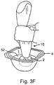
- a test run may be performed as illustrated in Fig. 3F by running the implant through the sleeve. After which, the implant is re-loaded in the sleeve for implantation deployment. Performing such a test run offers a valuable fit check, especially when the sleeve end had been trimmed to accommodate larger-sized implants to ensure that the implant will push-out cleanly.
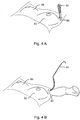
- Figs. 4A-4D illustrate use of the subject device in delivering an implant employing a transaxillary approach.
- An incision 60 is created in an axillary site leading to a subcutaneous pocket (not shown) under left breast 62.
- the pocket may be formed by employing various dissection techniques known to skilled practitioners.
- the access incision is shown held open by a small retractor 40.
- the pocket itself may be created in either the subglandular or subpectoral space.
- the submuscular plane tends to be less vascular, and is associated with fewer sensory alterations of the nipple areolar complex. So, a subpectoral pocket may be preferred.
- Fig. 4B illustrates a larger Deaver retractor passing through incision 60 into the breast pocket.
- the distal tip of sleeve 10 is received within the incision.
- the retractor may be used to urge the surgical pocket open and/or bear down on the sleeve as described above.
- Fig. 4D illustrates left breast 62 enlarged as desired. Once right breast 64 is similarly treated and symmetry confirmed (with any subsequent adjustments made), the breast pocket incisions are closed.
- FIG. 5A illustrates a first sizer emplaced using a periareolar approach (sizer fill tube 70 shown).
- Fig. 5B shows the Deaver retractor inserted into the right breast 64 pocket and sleeve 10 being introduced into the incision. In doing so, the tip or distal end of the sleeve may be crimped or crumpled-down as shown to aid in passing through the incision.
- the same technique may be employed irrespective of access approach chosen. However, the technique may be more helpful or necessary for introduction into smaller incisions.
- FIG. 5C illustrates implant extrusion into the breast pocket much as shown in Fig. 4C .
- a complete augmentation procedure (save final incision closure) in which both breasts 62 and 64 are filled is presented in Fig. 5D .
- the step of inserting a prefilled silicone implant can occur within a timeframe of about 5 to about 20 seconds employing the subject invention as compared to a time interval of up to 5 to 15 minutes for a traditional hand manipulation of the same implant. Additionally, because the implant can be inserted through a small opening, the size of the surgical incision can be made smaller than would otherwise be required for a silicone implant. Essentially, saline implant-size incisions can effectively be used to deliver pre-filled silicone implants.
- Illustrative examples of such use under confidential clinical site conditions include: Incision Site Implant Style Sleeve Opening Size (cm)* Exterior Incision Size (cm) Silicon Breast Implant Volume (cc) Left Right Left Right Axillary Moderate Plus 4.5 3.2 3.5 275 300 Periaerolar Moderate Plus 6.0 5.0 5.0 550 550 Periaerolar Moderate Plus 5.5 5.5 5.5 400 400 Periaerolar Moderate Plus 6.0 4.0 4.0 400 400 Periaerolar High Profile Smooth Round 5.5 3.0 3.5 500 500 * Opening Size measured when sleeve is laid flat on table.
- a larger silicone implant can be delivered for a given incision-size as will be appreciated by those with skill in the art. Such a consideration may be important especially when considering a periareolar approach as illustrated in Figs. 5A-5D .
- the periareolar approach may sometimes be preferred because the color of the areola can offer "camouflage" to help the incision scar blend in.
- the periareolar approach is often less surgically challenging than a transaxial approach. But since the size of the incision is coordinated with that of the areola in a periareolar approach, the size of pre-filled implant that could previously be inserted therethrough is sometimes limited. Use of the subject device relaxes this limitation, thereby offer each of the patient and surgeon more (often better) options.
- the invention includes the methods set forth above in terms of method of preparation. The methods may be performed using the subject devices and sometimes by other means.
- the methods may include the act of providing a suitable device. Such provision may be performed by the end user. In other words, the act of "providing” merely requires that the end user access, approach, position, setup, grasp or otherwise obtain the requisite device for the subject method. Methods recited herein may be carried out in any order of the recited events which is logically possible, as well as in the recited order of events.
Landscapes
- Health & Medical Sciences (AREA)
- Cardiology (AREA)
- Oral & Maxillofacial Surgery (AREA)
- Transplantation (AREA)
- Engineering & Computer Science (AREA)
- Biomedical Technology (AREA)
- Heart & Thoracic Surgery (AREA)
- Vascular Medicine (AREA)
- Life Sciences & Earth Sciences (AREA)
- Animal Behavior & Ethology (AREA)
- General Health & Medical Sciences (AREA)
- Public Health (AREA)
- Veterinary Medicine (AREA)
- Prostheses (AREA)
Description
- The present invention relates to an apparatus for manually delivering a pre-filled breast implant into a surgical pocket.
- Silicone breast implants were re-approved in the United States in November 2006 after having been withdrawn from the market. Implant recipients cite safety, scarring, and "natural" look and feel to be the top three indicators in selecting between saline- and silicone-filled implants for breast augmentation. Given that the more natural look and feel offered by silicon is a pre-requisite for many patients, silicone implants have already achieved nearly 50% market share following their return to the market.
- But because silicone implants are pre-filled (to alleviate leakage concerns) they have generally required larger access incisions than saline implants. Due to the possibility of visible scars associated with the larger incisions, some patients have remained apprehensive about selecting silicone implants.
- An additional consideration that has thus-far weighed against silicone implant selection involves the amount of time required for insertion. Hand manipulation can be time consuming even a highly skilled surgical practitioner. The time spent has a direct bearing on the expense of the procedure.
- The extent (and nature) of such manipulation also impacts the safety of the procedure. Stated plainly, the poking and pushing required to manually insert a prefilled silicone implant can be quite rough. Indeed, clinical studies have shown that the majority of silicone implant leaks/ruptures are attributable to sharp instrument damage and/or local stress forces exerted on the implant at the time of insertion.
- Advances have been made in the construction methods and materials used in silicone breast implants over the last decade (e.g., the introduction of cohesive gels, textured shells, and anatomical shapes). However, little improvement has been made in the method of inserting the implants. That is, until use of the device described in
US Patent Application Serial No. 12/228,072 to Keller , published asUS 2009/0204107 . - The Keller filing describes a device and methods addressing each of the above-referenced issues. It discloses a specially-adapted pastry bag type device for implant introduction. The device enables silicon implant insertion though smaller incisions at dramatically reduced introduction time as compared to the common practice for silicon implant introduction. Likewise, the potential for implant damage has been significantly reduced. By addressing the cited delivery challenges through use of the Keller device, the popularity of silicon-based implants is poised to overtake that of saline-filed counterparts. This scenario is made more likely given ultimate market introduction of the Keller device with improvements as described herein.
US2007276484 relates to a method and apparatus for inserting a flexible implant into a human or animal body. Insertion is accomplished through a relatively small incision in the body and utilizes a fabric carrier and funnel-shaped introducer with a retrograde propulsion system. - In a first aspect, according to claim 1, there is provided an apparatus for inserting a pre-filled prosthesis into a surgical pocket. In a second aspect, according to claim 8, there is provided a method for preparing a delivery system for use in implanting a pre-filed prosthesis into a surgical pocket.
- Like the original Keller device, the present invention comprises a truncated conical sleeve. The frustum-shaped device is adapted to receive a silicon breast implant and by squeezing the sleeve, expel the implant from its smaller end into a tissue pocket. The implant delivery sleeve is constructed of a flexible fabric and similar in size to store-bought pastry bags.
- More specifically, since the size of silicone implants may vary in a range from about 150 cc to about 800 cc, the dimensions of the sleeve may vary. A proximal opening sized to fit any implant in this size range and a distal opening sized to fit the smallest implant may be desirable. The distal/tip opening then may be enlarged by trimming the sleeve to provide a larger opening. Indicia may be present on the exterior of sleeve as a guide for cutting to the proper dimensions.
- In use, the small end of the delivery sleeve is placed through a skin incision into a tissue pocket and pressure is applied to force the implant from the sleeve into the pocket in use. Such action avoids rough or gross manipulation as required by manual implantation. As such, use of the sleeve makes for a more "gentle" procedure reducing the potential for implant damage and/or adjacent tissue trauma.
- In addition, the small size of the delivery sleeve opening allows the physician flexibility in his/her surgical approach by allowing the access through the inframammary, periareolar, or axillary sites. In all cases, the incision is smaller and less noticeable than otherwise required for inserting silicone implants, thereby diminishing any scarring.
- While similarly advantageous in regard to the above, the present invention incorporates additional features and advantages in use as compared to the Keller system.
- For instance, the sleeve is advantageously constructed of rip-stop nylon fabric. In such construction, the fabric is advantageously between about 21.3 to about 42.5 g (about ¾ to about 1½ oz) weight material per 914.4 mm × 723.9 mm (sailmaker's yard). It may be as heavy 63.8 g (2¼ oz) or heavier still by the same standard. To offer maximum translucency when wet-out (a feature useful for determining/confirming implant orientation within the sleeve), the fabric is preferably not pigmented. Other material options are possible as well, but the rip-stop nylon offers particular advantages in terms of durability and ease of handling, especially in connection with its use as further described below.
- Other constructional features define another optional aspect of the present invention. Specifically, the device is advantageously cut from rip-stop nylon cloth that is adhered along an overlapping seam with double-sided tape. 3M, Inc. offers 0.127 mm (5 mil) transfer tape that is suitable for this purpose; suitable fabric may be obtained from Challenge Sailcloth, Inc. So-constructed, no binding of the fabric edges is required to prevent unraveling or other problems. Cost is utterly minimized, without any compromise in performance. Still, other constructional approaches may be employed without departing from other aspects of the present invention.
- Regardless, the interior of the sleeve is packaged and supplied with a user-activated coating thereon. This coating is a hydrophilic coating. It is user-activated by soaking the sleeve in fluid (e.g., deionized water or sterile saline solution) as further described below. It is stably adhered to or bonded to the sleeve. A number of coatings and/or suppliers thereof may supply and/or apply the coating. A preferred vendor is AST Products, Inc. applying LUBRILAST hydrophilic coating and/or other coating(s) as described in USPNs
6,238,799 and6,866,936 . Other suitable coatings can be applied as well to devices such as the device set forth in the KellerU.S. Patent Application Serial No. 12/228,072 filed on December 7, 2007 US 2009/0204107 . - So-coated, the interior of the sleeve becomes extremely slippery/lubricous when soaked. The lubricous coating adhered to the sleeve, then, controllably allows the silicone implant to be manipulated down and out of the tapered device into place by a squeezing/pushing motion. Preferably, such motion is applied to the sleeve proximal to the bulk of the implant. Delivering an implant by such action avoids damage to the implant and/or further fuss or fiddle in delivering a pre-filled implant, such as a silicone breast implant.
- The construction of the sleeve facilitates preparing it for use in the manner described by allowing compaction of the sleeve into a basin (i.e., a disposable bowl or other undersized container - such as the implant packaging itself - as typically available in an operating room). Specifically, the foldable (vs. merely flexible) nature of the fabric and non-interfering seam provide advantages. These features allow the device to be easily folded, crumpled or otherwise compacted to fit into such a container and at least substantially submerged in fluid without continued manual effort and/or compression under another object to push or hold it down. Moreover, such action (the compaction) is accomplished without damage to the sleeve. Ideally, no significant trace of the sleeve manipulation is evident when the device is put to use. That does not mean that no visual evidence of the manipulation remains. Rather, no structural damage has occurred.
- The coating may be applied to the subject device(s) in a number of ways. In one approach, if the end of the sleeve is open, it can be closed-off by an object (such as a ball) and the interior filled with coating fluid that is subsequently poured-out. In another approach, the exterior of the sleeve can be masked with a removable layer (e.g., adhered paper or tape) to avoid coating the outer surface when spraying or dip-coating. In another approach, the interior of the sleeve is blocked from receiving coating (e.g., by taping-off the ends of the sleeve with double-stick tape or otherwise) and only the exterior of the device is coated. After removing the tape (e.g., by cutting-off the sealed/blocked ends), the sleeve is rolled-over/everted so that now only the interior surface is coated. In any case, it is desirable to avoid hydrophilic coating on the exterior of the finished device in order to permit better physician grip on the sleeve after its soaking.
- The present invention includes such features as described above. Still further, it includes methods associated with and/or activities implicit to the preparing of the devices described.
- The figures provided herein are not necessarily drawn to scale, with some components and features being exaggerated for clarity. Each of the figures diagrammatically illustrates aspects of the invention. Of these:
Fig. 1 shows the subject sleeve and a pre-filled implant for delivery therethrough;Figs. 2A and 2B illustrate manipulation of the sleeve;Fig. 3A-3F illustrate preparatory acts in using the subject device;Figs 4A-4D illustrate use of the present invention in a breast augmentation procedure;Figs. 5A-5D illustrate use of the present invention in an alternative surgical approach for breast augmentation. Variation of the invention from the embodiments pictured is, of course, contemplated. Moreover, details commonly understood by those with skill in the art may be omitted. -
Fig. 1 illustrates apre-filled silicone implant 2 andsleeve 10 according to the present invention provided to facilitate implant delivery.Sleeve 10 has general conical shape that defines afirst opening 12 at a larger end and asmaller opening 14 at a terminal end. - The tip of the device may include indica 16 coordinated to various implant sizes to facilitate trimming the opening to the correct size. The indica provide a guide for a practitioner to cut along a selected line in order to size the exit diameter of the device for a given implant in a size range, for example, of between about 150 cc to about 800 cc. By so-trimming the sleeve, exit diameters from between about 3 cm to about 6 cm are provided. For a more typical range of implant sizes, the openings may be sized approximately as follows (width dimension measured with the sleeve laid flat): 4.5 cm for 300cc implants, 5.0 cm for 300cc to 450cc implants, and 5.5 cm for 450cc to 550cc implants.
-
Sleeve 10 is advantageously constructed with aseam 18 formed using double-sided tape to close overlappingedges - Apart from such optional aspects,
sleeve 10, necessarily includes a user-activatedlubricious coating 24 adhered to the interior of the sleeve. So-coated, no introduction of further lubricant into the sleeve or over the surface of the implant is required for implant delivery. Instead coating 24 is stably adhered to the sleeve, and simply activated (e.g., by hydration) for use. Such a coating substantially mitigates or altogether eliminates risk associated with the introduction of additional foreign body material (in the form of applied lubricant) into the patient along with the implant. - Given that lubricant need not be applied to the surface of the implant and that the implant is neither directly manipulated during delivery nor introduced in such a way that it touches the recipient's skin, the implantation procedure may proceed as a "no touch" approach. Such an approach is advisable in avoiding capsular contracture.
- Capsular contracture is an abnormal response of the immune system to foreign materials. The exact cause of contracture is not known. However, noted factors include bacterial contamination, silicone breast implant rupture or leakage, and hematoma. Methods which have reduced capsular contracture include limiting handling of the implants and skin contact prior to insertion as well as irrigation with triple-antibiotic solutions. Use of the present invention easily enables practicing these methods and further addresses the noted factors as a gentle, no-touch means of implant delivery.
- As shown in
Figs. 2A and 2B , when animplant 2, such as a silicone implant, is set intosleeve 10, the sleeve can be manipulated to apply pressure to direct the implant along the length of the sleeve and towarddistal opening 14. The flexible sleeve is conformed to the implant where there is slack in the material, and the implant to the sleeve where sleeve material is taut. The largerproximal opening 12 of the sleeve allows for implant introduction into the sleeve with little or substantially no digital force or manual manipulation. - With the implant set within the sleeve, the
sleeve body 26 may be twisted closed. By any combination of such twisting and progressive compression action (such progression illustrated in transition fromFig. 2A to Fig. 2B ) the surgeon is able to apply pressure via the sleeve to the implant and force it out of the delivery device and into a surgical pocket as illustrated in subsequent figures. Generally, aproximal hand 30 grip is used primarily to drive the implant forward, with thedistal hand 32 grip more for offering stability and guidance to the end of the sleeve. - In addition, when introducing the implant into a surgical pocket, the pocket can be manipulated by a retractor to force the pocket open. Such action opens the void/space into which the implant is to be set, and may further help draw the implant inward by creating a partial vacuum. Moreover (although by no means necessary), the retractor may next be brought to bear on the sleeve to further assist the user's manipulation of the sleeve to extrude the implant into the surgical pocket.
-
Figs. 3A-3F offer more detail regarding use of the subject delivery sleeve. Specifically, this series of figures illustrates the manner in which the sleeve and an implant are prepared.Fig. 3A shows each animplant 2 in itspackaging 4, the sleeve 10 (removed from sterile packaging),scissors 40, and abasin 50 as typically found in a surgical suite. The basin is shown partially filled with saline 52 (optionally including antibiotic solution and/or Betadine®). To activate the lubricious coating inside the sleeve, the sleeve is folded or simply pushed intobasin 50 in a compacted state as shown inFig. 3B to soak. The sleeve preferably remains in fluid until time for use. - At least some of the fluid in the basin can be poured-off into the
implant packaging container 4 as shown inFig. 3C in order to bathe the implant in solution (especially useful if loaded with antibiotics) prior to implantation. - If trimming the sleeve end is desired in order to better fit a specific implant size, it may occur next as illustrated in
Fig.3D . However,sleeve 10 may be trimmed as soon as it is unpackaged. Alternatively, the delivery sleeve may be specifically sized and/or packaged in coordination with a given size of implant to avoid any such need. -
Fig. 3E illustrates thesleeve 10 with an implant therein. Because of the translucent nature of the sleeve material, implant orientation can be visually confirmed as indicated in relation to the landmark offered by thetape seam 18. Prior to delivering the implant in a medical procedure, a test run may be performed as illustrated inFig. 3F by running the implant through the sleeve. After which, the implant is re-loaded in the sleeve for implantation deployment. Performing such a test run offers a valuable fit check, especially when the sleeve end had been trimmed to accommodate larger-sized implants to ensure that the implant will push-out cleanly. -
Figs. 4A-4D illustrate use of the subject device in delivering an implant employing a transaxillary approach. Anincision 60 is created in an axillary site leading to a subcutaneous pocket (not shown) under leftbreast 62. The pocket may be formed by employing various dissection techniques known to skilled practitioners. The access incision is shown held open by asmall retractor 40. The pocket itself may be created in either the subglandular or subpectoral space. The submuscular plane tends to be less vascular, and is associated with fewer sensory alterations of the nipple areolar complex. So, a subpectoral pocket may be preferred. - In any case,
Fig. 4B illustrates a larger Deaver retractor passing throughincision 60 into the breast pocket. In addition, the distal tip ofsleeve 10 is received within the incision. As shown inFig. 4C , while the implant is squeezed forward along the sleeve, the retractor may be used to urge the surgical pocket open and/or bear down on the sleeve as described above. -
Fig. 4D illustrates leftbreast 62 enlarged as desired. Onceright breast 64 is similarly treated and symmetry confirmed (with any subsequent adjustments made), the breast pocket incisions are closed. - Note, prior to undertaking implant delivery, an inflatable sizer will typically be placed in the pocket under each breast. These sizer(s) may be placed to aid in prosthesis size selection, and can also be over-filled to provide intraoperative tissue expansion.
Fig. 5A illustrates a first sizer emplaced using a periareolar approach (sizer filltube 70 shown). With a second sizer in place,Fig. 5B shows the Deaver retractor inserted into theright breast 64 pocket andsleeve 10 being introduced into the incision. In doing so, the tip or distal end of the sleeve may be crimped or crumpled-down as shown to aid in passing through the incision. - Indeed, the same technique may be employed irrespective of access approach chosen. However, the technique may be more helpful or necessary for introduction into smaller incisions.
-
Fig. 5C illustrates implant extrusion into the breast pocket much as shown inFig. 4C . A complete augmentation procedure (save final incision closure) in which bothbreasts Fig. 5D . - Regardless of the surgical approach taken, it has been found that the step of inserting a prefilled silicone implant can occur within a timeframe of about 5 to about 20 seconds employing the subject invention as compared to a time interval of up to 5 to 15 minutes for a traditional hand manipulation of the same implant. Additionally, because the implant can be inserted through a small opening, the size of the surgical incision can be made smaller than would otherwise be required for a silicone implant. Essentially, saline implant-size incisions can effectively be used to deliver pre-filled silicone implants.
- Illustrative examples of such use under confidential clinical site conditions include:
Incision Site Implant Style Sleeve Opening Size (cm)* Exterior Incision Size (cm) Silicon Breast Implant Volume (cc) Left Right Left Right Axillary Moderate Plus 4.5 3.2 3.5 275 300 Periaerolar Moderate Plus 6.0 5.0 5.0 550 550 Periaerolar Moderate Plus 5.5 5.5 5.5 400 400 Periaerolar Moderate Plus 6.0 4.0 4.0 400 400 Periaerolar High Profile Smooth Round 5.5 3.0 3.5 500 500 * Opening Size measured when sleeve is laid flat on table. - Viewed otherwise, a larger silicone implant can be delivered for a given incision-size as will be appreciated by those with skill in the art. Such a consideration may be important especially when considering a periareolar approach as illustrated in
Figs. 5A-5D . - The periareolar approach may sometimes be preferred because the color of the areola can offer "camouflage" to help the incision scar blend in. The periareolar approach is often less surgically challenging than a transaxial approach. But since the size of the incision is coordinated with that of the areola in a periareolar approach, the size of pre-filled implant that could previously be inserted therethrough is sometimes limited. Use of the subject device relaxes this limitation, thereby offer each of the patient and surgeon more (often better) options.
- The invention includes the methods set forth above in terms of method of preparation. The methods may be performed using the subject devices and sometimes by other means.
- The methods may include the act of providing a suitable device. Such provision may be performed by the end user. In other words, the act of "providing" merely requires that the end user access, approach, position, setup, grasp or otherwise obtain the requisite device for the subject method. Methods recited herein may be carried out in any order of the recited events which is logically possible, as well as in the recited order of events.
- Exemplary aspects of the invention, together with details regarding material selection and manufacture have been set forth above. As for other details of the present invention, these may be appreciated in connection with the above-referenced patents and publications as well as generally known or appreciated by those with skill in the art. The same may hold true with respect to method-based aspects of the invention in terms of additional acts as commonly or logically employed.
- In addition, though the invention has been described in reference to several examples, optionally incorporating various features, the invention is not to be limited to that which is described or indicated as contemplated with respect to each variation of the invention. Various changes may be made to the invention described (whether recited herein or not included for the sake of some brevity) may be substituted without departing from the scope of the invention. In addition, where a range of values is provided, it is understood that every intervening value, between the upper and lower limit of that range and any other stated or intervening value in that stated range is encompassed within the invention.
- Reference to a singular item, includes the possibility that there are plural of the same items present. More specifically, as used herein and in the appended claims, the singular forms "a," "an," "said," and "the" include plural referents unless specifically stated otherwise. In other words, use of the articles allow for "at least one" of the subject item in the description above as well as the claims below.
- Without the use of such exclusive terminology, the term "comprising" in the claims shall allow for the inclusion of any additional element - irrespective of whether a given number of elements are enumerated in the claim, or the addition of a feature could be regarded as transforming the nature of an element set forth in the claims. Except as specifically defined herein, all technical and scientific terms used are to be given as broad a commonly understood meaning as possible while maintaining claim validity.
Claims (9)
- An apparatus for delivering a pre-filled prosthesis into a surgical pocket, the prosthesis being a breast implant, the apparatus comprising:a flexible sleeve (10) including a proximal opening (12), a distal opening (14), and an interior with a hydrophilic coating adhered thereon, wherein said coating is adapted to become lubricious when the flexible sleeve (10) is soaked in fluid,wherein the sleeve (10) is tapered, wherein the proximal opening (12) is relatively larger than the distal opening (14), andwherein the sleeve (10) is adapted to be manually manipulatable to apply pressure via the sleeve (10) to the prosthesis to push the prosthesis along the interior and through the distal opening (14).
- The apparatus of claim 1, wherein a periphery of the sleeve (10) at a distal terminal end of the sleeve (10) defines the distal opening (14).
- The apparatus of claim 1, wherein a periphery of the sleeve (10) at a proximal end of the sleeve (10) defines the proximal opening (12).
- The apparatus of claim 1, wherein the sleeve (10) includes indicia (16) coordinated to various implant sizes, the indicia providing a guide for trimming the distal opening (14) of the sleeve (10) to the correct size.
- The apparatus of claim 1, wherein the sleeve (10) has a seam (18) along its length.
- The apparatus of claim 1, wherein the hydrophilic coating is adapted to become lubricious with hydration.
- The apparatus of claim 1, wherein the sleeve (10) is translucent.
- A method of preparing a delivery system for use in implanting a pre-filled prosthesis into a surgical pocket, the prosthesis being a breast implant, and the method comprising:providing the apparatus of claim 1;fitting the sleeve (10) of said apparatus into a basin (50) in a compacted state, the basin (50) at least partially filled with fluid;soaking the sleeve (10) in the fluid to activate the hydrophilic coating adhered to an inner surface of the sleeve (10), wherein said hydropholic coating becomes lubricious;removing the sleeve (10) from the basin (50); andinserting the prosthesis (2) into the sleeve (10) through the proximal opening (12)
- A method according to claim 8, comprising the further step of:
manipulating the sleeve (10) to conform to a shape of the prosthesis and apply pressure to direct the prosthesis along the length of the sleeve (10) toward the distal opening (14), out of the distal opening (14); and reinserting the prosthesis into the sleeve (10) to be ready for prosthesis implantation.
Applications Claiming Priority (1)
| Application Number | Priority Date | Filing Date | Title |
|---|---|---|---|
| PCT/US2009/002592 WO2010126462A1 (en) | 2009-04-29 | 2009-04-29 | Silicone breast implant delivery |
Publications (3)
| Publication Number | Publication Date |
|---|---|
| EP2424466A1 EP2424466A1 (en) | 2012-03-07 |
| EP2424466A4 EP2424466A4 (en) | 2012-10-10 |
| EP2424466B1 true EP2424466B1 (en) | 2021-11-10 |
Family
ID=43032408
Family Applications (1)
| Application Number | Title | Priority Date | Filing Date |
|---|---|---|---|
| EP09844125.6A Revoked EP2424466B1 (en) | 2009-04-29 | 2009-04-29 | Apparatus for silicone breast implant delivery |
Country Status (4)
| Country | Link |
|---|---|
| EP (1) | EP2424466B1 (en) |
| CA (1) | CA2760551C (en) |
| ES (1) | ES2898968T3 (en) |
| WO (1) | WO2010126462A1 (en) |
Families Citing this family (13)
| Publication number | Priority date | Publication date | Assignee | Title |
|---|---|---|---|---|
| US8206443B2 (en) | 2009-04-29 | 2012-06-26 | Keller Medical, Inc. | Fail-safe silicone breast implant delivery device |
| US10722335B1 (en) | 2016-11-15 | 2020-07-28 | Proximate Concepts Llc | Device for the delivery of a prosthetic implant and method of use thereof |
| US9925028B1 (en) | 2016-11-15 | 2018-03-27 | Proximate Concepts Llc | Device for the delivery of a prosthetic implant and method of use thereof |
| LT3627996T (en) * | 2017-04-25 | 2023-03-10 | Weinzweig, Jeffrey , M.D. | Prosthetic implant delivery device |
| US10939985B2 (en) * | 2017-07-12 | 2021-03-09 | R. Alastair Winn | Sterile lubricated breast implant |
| US12201512B2 (en) | 2018-03-06 | 2025-01-21 | Mentor Worldwide Llc | Delivery sleeve |
| US11311369B2 (en) | 2018-03-06 | 2022-04-26 | Mentor Worldwide Llc | Delivery sleeve |
| US11903814B2 (en) * | 2018-03-06 | 2024-02-20 | Mentor Worldwide Llc | Delivery sleeve |
| US20200008923A1 (en) * | 2018-07-09 | 2020-01-09 | Sientra, Inc. | Implant delivery system and method |
| US11850135B2 (en) | 2019-08-01 | 2023-12-26 | Paul H. Rosenberg Family Trust | Prosthetic implant delivery device utilizing surface active agents |
| US11786360B2 (en) | 2020-07-01 | 2023-10-17 | Mentor Worldwide Llc | Encoded cinching mechanism for use with an implant delivery sleeve |
| US12102354B2 (en) | 2021-09-29 | 2024-10-01 | Mentor Worldwide Llc | Implant delivery sleeves having non-tapered tubular walls with constricted implant delivery channels for inserting implants into tissue pockets |
| CN114306883A (en) * | 2022-01-05 | 2022-04-12 | 聚辉医疗科技(深圳)有限公司 | Method for manufacturing microcatheter and microcatheter |
Citations (3)
| Publication number | Priority date | Publication date | Assignee | Title |
|---|---|---|---|---|
| US20020018898A1 (en) | 1996-02-09 | 2002-02-14 | Opolski Margaret P. | Water-based hydrophilic coating compositions and articles prepared therefrom |
| US20070276484A1 (en) | 2006-05-26 | 2007-11-29 | Insertion, Llc | Method and apparatus for insertion of a flexible implant into the human body |
| US20090204107A1 (en) | 2007-12-07 | 2009-08-13 | Kevin Keller | Apparatus and process for delivering a silicone prosthesis into a surgical pocket |
Family Cites Families (2)
| Publication number | Priority date | Publication date | Assignee | Title |
|---|---|---|---|---|
| FR2733903B1 (en) * | 1995-05-11 | 1997-11-07 | Arion Henri | DEVICE FOR INTRODUCING A PROSTHETIC IMPLANT |
| US6383191B1 (en) * | 2000-03-15 | 2002-05-07 | Sdgi Holdings, Inc. | Laparoscopic instrument sleeve |
-
2009
- 2009-04-29 EP EP09844125.6A patent/EP2424466B1/en not_active Revoked
- 2009-04-29 WO PCT/US2009/002592 patent/WO2010126462A1/en not_active Ceased
- 2009-04-29 ES ES09844125T patent/ES2898968T3/en active Active
- 2009-04-29 CA CA2760551A patent/CA2760551C/en active Active
Patent Citations (3)
| Publication number | Priority date | Publication date | Assignee | Title |
|---|---|---|---|---|
| US20020018898A1 (en) | 1996-02-09 | 2002-02-14 | Opolski Margaret P. | Water-based hydrophilic coating compositions and articles prepared therefrom |
| US20070276484A1 (en) | 2006-05-26 | 2007-11-29 | Insertion, Llc | Method and apparatus for insertion of a flexible implant into the human body |
| US20090204107A1 (en) | 2007-12-07 | 2009-08-13 | Kevin Keller | Apparatus and process for delivering a silicone prosthesis into a surgical pocket |
Non-Patent Citations (5)
| Title |
|---|
| ANONYMOUS: "FORM D Notice of Exempt Offering of Securities", UNITED STATES SECURITIES AND EXCHANGE COMMISSION, 19 March 2009 (2009-03-19), XP055945630, [retrieved on 20220725] |
| KELLER KEVIN, PREISSMAN HOWARD: "How the Keller Funnel Got its Start", THE AMERICAN JOURNAL OF COSMETIC SURGERY, vol. 29, no. 4, 1 December 2012 (2012-12-01), pages 283 - 285, XP055945629, ISSN: 0748-8068, DOI: 10.5992/AJCS-D-12-00035.1 |
| RICHARD L.DOLSKY .MD: "Ideas and Innovations, INSERING THE MEME PROTHESIS ", PLASTIC AND RECONSTRUCTIVE SURGERY, vol. 73, no. 3, 1 March 1984 (1984-03-01), pages 466 - 468, XP055945631 |
| SECURITIES AND EXCHANGE COMMISSION REGULATIONS, vol. 3, 25 November 2021 (2021-11-25), pages 93 - 95 |
| SG BELL MICHAEL, MCKEE DANIEL: "An Illuminating No-Touch Device for Breast Augmentation", CANADIAN JOURNAL OF PLASTIC SURGERY, SAGE PUBLICATIONS, LOS ANGELES, CA, vol. 17, no. 1, 1 March 2009 (2009-03-01), Los Angeles, CA, pages 30 - 31, XP055945632, ISSN: 2292-5503, DOI: 10.1177/229255030901700101 |
Also Published As
| Publication number | Publication date |
|---|---|
| CA2760551A1 (en) | 2010-11-04 |
| EP2424466A4 (en) | 2012-10-10 |
| EP2424466A1 (en) | 2012-03-07 |
| CA2760551C (en) | 2018-01-09 |
| ES2898968T3 (en) | 2022-03-09 |
| WO2010126462A1 (en) | 2010-11-04 |
Similar Documents
| Publication | Publication Date | Title |
|---|---|---|
| US20250387218A1 (en) | Silicone breast implant delivery | |
| CA2760551C (en) | Silicone breast implant delivery | |
| US8206443B2 (en) | Fail-safe silicone breast implant delivery device | |
| US11622791B2 (en) | Apparatuses for the implantation of medical devices and methods of use thereof | |
| US20150032208A1 (en) | Devices, systems, and methods for implant delivery | |
| WO2013122568A1 (en) | Devices, systems, and methods for implant delivery | |
| US20090204107A1 (en) | Apparatus and process for delivering a silicone prosthesis into a surgical pocket | |
| KR20190085909A (en) | Sealed distal end implant insertion bag | |
| US10842613B2 (en) | Devices and methods for implantation procedures | |
| US20210244527A1 (en) | Silicone Prosthesis Delivery Apparatus and Methods of Use | |
| US20110172496A1 (en) | Device for transaxillary breast augmentation and associated method | |
| HK40083025A (en) | Apparatuses for the implantation of medical devices | |
| HK40083025B (en) | Apparatuses for the implantation of medical devices | |
| TW201717861A (en) | A kit for introducing a bladder into a body pocket | |
| WO2017091999A1 (en) | A kit for introducing a bladder into a body pocket |
Legal Events
| Date | Code | Title | Description |
|---|---|---|---|
| PUAI | Public reference made under article 153(3) epc to a published international application that has entered the european phase |
Free format text: ORIGINAL CODE: 0009012 |
|
| 17P | Request for examination filed |
Effective date: 20111128 |
|
| AK | Designated contracting states |
Kind code of ref document: A1 Designated state(s): AT BE BG CH CY CZ DE DK EE ES FI FR GB GR HR HU IE IS IT LI LT LU LV MC MK MT NL NO PL PT RO SE SI SK TR |
|
| DAX | Request for extension of the european patent (deleted) | ||
| A4 | Supplementary search report drawn up and despatched |
Effective date: 20120906 |
|
| RIC1 | Information provided on ipc code assigned before grant |
Ipc: A61F 2/12 20060101AFI20120831BHEP |
|
| 17Q | First examination report despatched |
Effective date: 20160418 |
|
| STAA | Information on the status of an ep patent application or granted ep patent |
Free format text: STATUS: EXAMINATION IS IN PROGRESS |
|
| GRAP | Despatch of communication of intention to grant a patent |
Free format text: ORIGINAL CODE: EPIDOSNIGR1 |
|
| STAA | Information on the status of an ep patent application or granted ep patent |
Free format text: STATUS: GRANT OF PATENT IS INTENDED |
|
| INTG | Intention to grant announced |
Effective date: 20210526 |
|
| GRAS | Grant fee paid |
Free format text: ORIGINAL CODE: EPIDOSNIGR3 |
|
| GRAA | (expected) grant |
Free format text: ORIGINAL CODE: 0009210 |
|
| STAA | Information on the status of an ep patent application or granted ep patent |
Free format text: STATUS: THE PATENT HAS BEEN GRANTED |
|
| AK | Designated contracting states |
Kind code of ref document: B1 Designated state(s): AT BE BG CH CY CZ DE DK EE ES FI FR GB GR HR HU IE IS IT LI LT LU LV MC MK MT NL NO PL PT RO SE SI SK TR |
|
| REG | Reference to a national code |
Ref country code: GB Ref legal event code: FG4D |
|
| REG | Reference to a national code |
Ref country code: AT Ref legal event code: REF Ref document number: 1445357 Country of ref document: AT Kind code of ref document: T Effective date: 20211115 Ref country code: CH Ref legal event code: EP |
|
| REG | Reference to a national code |
Ref country code: DE Ref legal event code: R096 Ref document number: 602009064152 Country of ref document: DE |
|
| REG | Reference to a national code |
Ref country code: IE Ref legal event code: FG4D |
|
| REG | Reference to a national code |
Ref country code: DE Ref legal event code: R081 Ref document number: 602009064152 Country of ref document: DE Owner name: KELLER MEDICAL, INC., NORTH CHICAGO, US Free format text: FORMER OWNER: KELLER MEDICAL, INC., STUART, FL, US |
|
| RAP4 | Party data changed (patent owner data changed or rights of a patent transferred) |
Owner name: KELLER MEDICAL, INC. |
|
| REG | Reference to a national code |
Ref country code: ES Ref legal event code: FG2A Ref document number: 2898968 Country of ref document: ES Kind code of ref document: T3 Effective date: 20220309 |
|
| REG | Reference to a national code |
Ref country code: LT Ref legal event code: MG9D |
|
| REG | Reference to a national code |
Ref country code: NL Ref legal event code: MP Effective date: 20211110 |
|
| REG | Reference to a national code |
Ref country code: AT Ref legal event code: MK05 Ref document number: 1445357 Country of ref document: AT Kind code of ref document: T Effective date: 20211110 |
|
| PG25 | Lapsed in a contracting state [announced via postgrant information from national office to epo] |
Ref country code: LT Free format text: LAPSE BECAUSE OF FAILURE TO SUBMIT A TRANSLATION OF THE DESCRIPTION OR TO PAY THE FEE WITHIN THE PRESCRIBED TIME-LIMIT Effective date: 20211110 Ref country code: FI Free format text: LAPSE BECAUSE OF FAILURE TO SUBMIT A TRANSLATION OF THE DESCRIPTION OR TO PAY THE FEE WITHIN THE PRESCRIBED TIME-LIMIT Effective date: 20211110 Ref country code: BG Free format text: LAPSE BECAUSE OF FAILURE TO SUBMIT A TRANSLATION OF THE DESCRIPTION OR TO PAY THE FEE WITHIN THE PRESCRIBED TIME-LIMIT Effective date: 20220210 Ref country code: AT Free format text: LAPSE BECAUSE OF FAILURE TO SUBMIT A TRANSLATION OF THE DESCRIPTION OR TO PAY THE FEE WITHIN THE PRESCRIBED TIME-LIMIT Effective date: 20211110 |
|
| REG | Reference to a national code |
Ref country code: DE Ref legal event code: R082 Ref document number: 602009064152 Country of ref document: DE Representative=s name: SIMMONS & SIMMONS LLP, DE |
|
| PG25 | Lapsed in a contracting state [announced via postgrant information from national office to epo] |
Ref country code: IS Free format text: LAPSE BECAUSE OF FAILURE TO SUBMIT A TRANSLATION OF THE DESCRIPTION OR TO PAY THE FEE WITHIN THE PRESCRIBED TIME-LIMIT Effective date: 20220310 Ref country code: SE Free format text: LAPSE BECAUSE OF FAILURE TO SUBMIT A TRANSLATION OF THE DESCRIPTION OR TO PAY THE FEE WITHIN THE PRESCRIBED TIME-LIMIT Effective date: 20211110 Ref country code: PT Free format text: LAPSE BECAUSE OF FAILURE TO SUBMIT A TRANSLATION OF THE DESCRIPTION OR TO PAY THE FEE WITHIN THE PRESCRIBED TIME-LIMIT Effective date: 20220310 Ref country code: PL Free format text: LAPSE BECAUSE OF FAILURE TO SUBMIT A TRANSLATION OF THE DESCRIPTION OR TO PAY THE FEE WITHIN THE PRESCRIBED TIME-LIMIT Effective date: 20211110 Ref country code: NO Free format text: LAPSE BECAUSE OF FAILURE TO SUBMIT A TRANSLATION OF THE DESCRIPTION OR TO PAY THE FEE WITHIN THE PRESCRIBED TIME-LIMIT Effective date: 20220210 Ref country code: NL Free format text: LAPSE BECAUSE OF FAILURE TO SUBMIT A TRANSLATION OF THE DESCRIPTION OR TO PAY THE FEE WITHIN THE PRESCRIBED TIME-LIMIT Effective date: 20211110 Ref country code: LV Free format text: LAPSE BECAUSE OF FAILURE TO SUBMIT A TRANSLATION OF THE DESCRIPTION OR TO PAY THE FEE WITHIN THE PRESCRIBED TIME-LIMIT Effective date: 20211110 Ref country code: HR Free format text: LAPSE BECAUSE OF FAILURE TO SUBMIT A TRANSLATION OF THE DESCRIPTION OR TO PAY THE FEE WITHIN THE PRESCRIBED TIME-LIMIT Effective date: 20211110 Ref country code: GR Free format text: LAPSE BECAUSE OF FAILURE TO SUBMIT A TRANSLATION OF THE DESCRIPTION OR TO PAY THE FEE WITHIN THE PRESCRIBED TIME-LIMIT Effective date: 20220211 |
|
| REG | Reference to a national code |
Ref country code: DE Ref legal event code: R026 Ref document number: 602009064152 Country of ref document: DE |
|
| PLBI | Opposition filed |
Free format text: ORIGINAL CODE: 0009260 |
|
| PLAB | Opposition data, opponent's data or that of the opponent's representative modified |
Free format text: ORIGINAL CODE: 0009299OPPO |
|
| PG25 | Lapsed in a contracting state [announced via postgrant information from national office to epo] |
Ref country code: SK Free format text: LAPSE BECAUSE OF FAILURE TO SUBMIT A TRANSLATION OF THE DESCRIPTION OR TO PAY THE FEE WITHIN THE PRESCRIBED TIME-LIMIT Effective date: 20211110 Ref country code: RO Free format text: LAPSE BECAUSE OF FAILURE TO SUBMIT A TRANSLATION OF THE DESCRIPTION OR TO PAY THE FEE WITHIN THE PRESCRIBED TIME-LIMIT Effective date: 20211110 Ref country code: EE Free format text: LAPSE BECAUSE OF FAILURE TO SUBMIT A TRANSLATION OF THE DESCRIPTION OR TO PAY THE FEE WITHIN THE PRESCRIBED TIME-LIMIT Effective date: 20211110 Ref country code: DK Free format text: LAPSE BECAUSE OF FAILURE TO SUBMIT A TRANSLATION OF THE DESCRIPTION OR TO PAY THE FEE WITHIN THE PRESCRIBED TIME-LIMIT Effective date: 20211110 Ref country code: CZ Free format text: LAPSE BECAUSE OF FAILURE TO SUBMIT A TRANSLATION OF THE DESCRIPTION OR TO PAY THE FEE WITHIN THE PRESCRIBED TIME-LIMIT Effective date: 20211110 |
|
| 26 | Opposition filed |
Opponent name: IDEAL MEDICAL SOLUTIONS LTD Effective date: 20220713 |
|
| PLAX | Notice of opposition and request to file observation + time limit sent |
Free format text: ORIGINAL CODE: EPIDOSNOBS2 |
|
| R26 | Opposition filed (corrected) |
Opponent name: IDEAL MEDICAL SOLUTIONS LTD Effective date: 20220713 |
|
| PG25 | Lapsed in a contracting state [announced via postgrant information from national office to epo] |
Ref country code: SI Free format text: LAPSE BECAUSE OF FAILURE TO SUBMIT A TRANSLATION OF THE DESCRIPTION OR TO PAY THE FEE WITHIN THE PRESCRIBED TIME-LIMIT Effective date: 20211110 |
|
| REG | Reference to a national code |
Ref country code: CH Ref legal event code: PL |
|
| PLBB | Reply of patent proprietor to notice(s) of opposition received |
Free format text: ORIGINAL CODE: EPIDOSNOBS3 |
|
| REG | Reference to a national code |
Ref country code: BE Ref legal event code: MM Effective date: 20220430 |
|
| PG25 | Lapsed in a contracting state [announced via postgrant information from national office to epo] |
Ref country code: MC Free format text: LAPSE BECAUSE OF FAILURE TO SUBMIT A TRANSLATION OF THE DESCRIPTION OR TO PAY THE FEE WITHIN THE PRESCRIBED TIME-LIMIT Effective date: 20211110 Ref country code: LU Free format text: LAPSE BECAUSE OF NON-PAYMENT OF DUE FEES Effective date: 20220429 Ref country code: LI Free format text: LAPSE BECAUSE OF NON-PAYMENT OF DUE FEES Effective date: 20220430 Ref country code: CH Free format text: LAPSE BECAUSE OF NON-PAYMENT OF DUE FEES Effective date: 20220430 |
|
| PG25 | Lapsed in a contracting state [announced via postgrant information from national office to epo] |
Ref country code: BE Free format text: LAPSE BECAUSE OF NON-PAYMENT OF DUE FEES Effective date: 20220430 |
|
| PLCK | Communication despatched that opposition was rejected |
Free format text: ORIGINAL CODE: EPIDOSNREJ1 |
|
| PG25 | Lapsed in a contracting state [announced via postgrant information from national office to epo] |
Ref country code: IE Free format text: LAPSE BECAUSE OF NON-PAYMENT OF DUE FEES Effective date: 20220429 |
|
| APBM | Appeal reference recorded |
Free format text: ORIGINAL CODE: EPIDOSNREFNO |
|
| APBP | Date of receipt of notice of appeal recorded |
Free format text: ORIGINAL CODE: EPIDOSNNOA2O |
|
| APAH | Appeal reference modified |
Free format text: ORIGINAL CODE: EPIDOSCREFNO |
|
| P01 | Opt-out of the competence of the unified patent court (upc) registered |
Effective date: 20230331 |
|
| APBQ | Date of receipt of statement of grounds of appeal recorded |
Free format text: ORIGINAL CODE: EPIDOSNNOA3O |
|
| GRAT | Correction requested after decision to grant or after decision to maintain patent in amended form |
Free format text: ORIGINAL CODE: EPIDOSNCDEC |
|
| REG | Reference to a national code |
Ref country code: CH Ref legal event code: PK Free format text: BERICHTIGUNGEN |
|
| RIN2 | Information on inventor provided after grant (corrected) |
Inventor name: PREISSMAN, HOWARD E. |
|
| PG25 | Lapsed in a contracting state [announced via postgrant information from national office to epo] |
Ref country code: HU Free format text: LAPSE BECAUSE OF FAILURE TO SUBMIT A TRANSLATION OF THE DESCRIPTION OR TO PAY THE FEE WITHIN THE PRESCRIBED TIME-LIMIT; INVALID AB INITIO Effective date: 20090429 |
|
| PG25 | Lapsed in a contracting state [announced via postgrant information from national office to epo] |
Ref country code: MK Free format text: LAPSE BECAUSE OF FAILURE TO SUBMIT A TRANSLATION OF THE DESCRIPTION OR TO PAY THE FEE WITHIN THE PRESCRIBED TIME-LIMIT Effective date: 20211110 Ref country code: CY Free format text: LAPSE BECAUSE OF FAILURE TO SUBMIT A TRANSLATION OF THE DESCRIPTION OR TO PAY THE FEE WITHIN THE PRESCRIBED TIME-LIMIT Effective date: 20211110 |
|
| PG25 | Lapsed in a contracting state [announced via postgrant information from national office to epo] |
Ref country code: TR Free format text: LAPSE BECAUSE OF FAILURE TO SUBMIT A TRANSLATION OF THE DESCRIPTION OR TO PAY THE FEE WITHIN THE PRESCRIBED TIME-LIMIT Effective date: 20211110 |
|
| PG25 | Lapsed in a contracting state [announced via postgrant information from national office to epo] |
Ref country code: MT Free format text: LAPSE BECAUSE OF FAILURE TO SUBMIT A TRANSLATION OF THE DESCRIPTION OR TO PAY THE FEE WITHIN THE PRESCRIBED TIME-LIMIT Effective date: 20211110 |
|
| PGFP | Annual fee paid to national office [announced via postgrant information from national office to epo] |
Ref country code: FR Payment date: 20250319 Year of fee payment: 17 |
|
| PLAB | Opposition data, opponent's data or that of the opponent's representative modified |
Free format text: ORIGINAL CODE: 0009299OPPO |
|
| PLAB | Opposition data, opponent's data or that of the opponent's representative modified |
Free format text: ORIGINAL CODE: 0009299OPPO |
|
| R26 | Opposition filed (corrected) |
Opponent name: IDEAL MEDICAL SOLUTIONS LTD Effective date: 20220713 |
|
| PGFP | Annual fee paid to national office [announced via postgrant information from national office to epo] |
Ref country code: DE Payment date: 20250317 Year of fee payment: 17 |
|
| R26 | Opposition filed (corrected) |
Opponent name: IDEAL MEDICAL SOLUTIONS LTD Effective date: 20220713 |
|
| PGFP | Annual fee paid to national office [announced via postgrant information from national office to epo] |
Ref country code: ES Payment date: 20250514 Year of fee payment: 17 |
|
| PGFP | Annual fee paid to national office [announced via postgrant information from national office to epo] |
Ref country code: IT Payment date: 20250410 Year of fee payment: 17 |
|
| PLAB | Opposition data, opponent's data or that of the opponent's representative modified |
Free format text: ORIGINAL CODE: 0009299OPPO |
|
| REG | Reference to a national code |
Ref country code: CH Ref legal event code: L10 Free format text: ST27 STATUS EVENT CODE: U-0-0-L10-L00 (AS PROVIDED BY THE NATIONAL OFFICE) Effective date: 20251126 |
|
| R26 | Opposition filed (corrected) |
Opponent name: IDEAL MEDICAL SOLUTIONS LTD Effective date: 20220713 |
|
| REG | Reference to a national code |
Ref country code: DE Ref legal event code: R064 Ref document number: 602009064152 Country of ref document: DE Ref country code: DE Ref legal event code: R103 Ref document number: 602009064152 Country of ref document: DE |
|
| APBU | Appeal procedure closed |
Free format text: ORIGINAL CODE: EPIDOSNNOA9O |
|
| RDAF | Communication despatched that patent is revoked |
Free format text: ORIGINAL CODE: EPIDOSNREV1 |
|
| STAA | Information on the status of an ep patent application or granted ep patent |
Free format text: STATUS: PATENT REVOKED |
|
| RDAG | Patent revoked |
Free format text: ORIGINAL CODE: 0009271 |
|
| REG | Reference to a national code |
Ref country code: CH Ref legal event code: N12 Free format text: ST27 STATUS EVENT CODE: U-0-0-N10-N12 (AS PROVIDED BY THE NATIONAL OFFICE) Effective date: 20260325 |
|
| PGFP | Annual fee paid to national office [announced via postgrant information from national office to epo] |
Ref country code: GB Payment date: 20260320 Year of fee payment: 18 |
|
| 27W | Patent revoked |
Effective date: 20260120 |
|
| GBPR | Gb: patent revoked under art. 102 of the ep convention designating the uk as contracting state |
Effective date: 20260120 |