EP2424341A1 - Printed circuit board housing with tapered locking rails - Google Patents
Printed circuit board housing with tapered locking rails Download PDFInfo
- Publication number
- EP2424341A1 EP2424341A1 EP11176061A EP11176061A EP2424341A1 EP 2424341 A1 EP2424341 A1 EP 2424341A1 EP 11176061 A EP11176061 A EP 11176061A EP 11176061 A EP11176061 A EP 11176061A EP 2424341 A1 EP2424341 A1 EP 2424341A1
- Authority
- EP
- European Patent Office
- Prior art keywords
- sidewall
- locking rail
- guiderail
- pcb
- connector
- Prior art date
- Legal status (The legal status is an assumption and is not a legal conclusion. Google has not performed a legal analysis and makes no representation as to the accuracy of the status listed.)
- Withdrawn
Links
- 238000000034 method Methods 0.000 claims description 6
- XAGFODPZIPBFFR-UHFFFAOYSA-N aluminium Chemical compound [Al] XAGFODPZIPBFFR-UHFFFAOYSA-N 0.000 claims description 5
- 229910052782 aluminium Inorganic materials 0.000 claims description 5
- 230000013011 mating Effects 0.000 claims description 3
- 238000001125 extrusion Methods 0.000 claims description 2
- 230000007246 mechanism Effects 0.000 description 12
- 230000008901 benefit Effects 0.000 description 3
- 239000004020 conductor Substances 0.000 description 2
- 239000004642 Polyimide Substances 0.000 description 1
- 239000000463 material Substances 0.000 description 1
- 238000012986 modification Methods 0.000 description 1
- 230000004048 modification Effects 0.000 description 1
- 229920001721 polyimide Polymers 0.000 description 1
Images


Classifications
-
- H—ELECTRICITY
- H05—ELECTRIC TECHNIQUES NOT OTHERWISE PROVIDED FOR
- H05K—PRINTED CIRCUITS; CASINGS OR CONSTRUCTIONAL DETAILS OF ELECTRIC APPARATUS; MANUFACTURE OF ASSEMBLAGES OF ELECTRICAL COMPONENTS
- H05K7/00—Constructional details common to different types of electric apparatus
- H05K7/14—Mounting supporting structure in casing or on frame or rack
- H05K7/1401—Mounting supporting structure in casing or on frame or rack comprising clamping or extracting means
- H05K7/1402—Mounting supporting structure in casing or on frame or rack comprising clamping or extracting means for securing or extracting printed circuit boards
- H05K7/1404—Mounting supporting structure in casing or on frame or rack comprising clamping or extracting means for securing or extracting printed circuit boards by edge clamping, e.g. wedges
-
- Y—GENERAL TAGGING OF NEW TECHNOLOGICAL DEVELOPMENTS; GENERAL TAGGING OF CROSS-SECTIONAL TECHNOLOGIES SPANNING OVER SEVERAL SECTIONS OF THE IPC; TECHNICAL SUBJECTS COVERED BY FORMER USPC CROSS-REFERENCE ART COLLECTIONS [XRACs] AND DIGESTS
- Y10—TECHNICAL SUBJECTS COVERED BY FORMER USPC
- Y10T—TECHNICAL SUBJECTS COVERED BY FORMER US CLASSIFICATION
- Y10T29/00—Metal working
- Y10T29/49—Method of mechanical manufacture
- Y10T29/49826—Assembling or joining
- Y10T29/49947—Assembling or joining by applying separate fastener
Definitions
- the present invention relates to a housing for a printed circuit board (PCB), and in particular, to mounting a PCB to its housing.
- PCB printed circuit board
- one or more printed circuit boards are attached between two walls of a housing.
- Each wall typically has a channel into which the PCB is slid and clamped in place by a rather complicated wedge lock system.
- a conventional wedge lock system includes several trapezoidal wedges aligned end-to-end and connected to one another via a bolt extending through holes in each wedge. The bolt applies a longitudinal compressive force on the trapezoidal wedges forcing each adjacent trapezoidal wedge laterally in opposite directions. When such a wedge lock system is placed in the channels with the PCB, tightening the bolt provides a compressive force against the PCB and the channel, thus holding the PCB in place. Housings that utilize these conventional wedge lock systems can be relatively complicated, heavy, and expensive.
- an assembly includes a housing, a first locking rail, and a second locking rail.
- the housing has first and second sidewalls.
- First and second guiderails extend from the first sidewall toward the second sidewall.
- Third and fourth guiderails extend from the second sidewall toward the first sidewall.
- the first locking rail is positioned between the first guiderail and the second guiderail.
- the first locking rail has a first surface nearest the first guiderail and a second surface nearest the second guiderail. The first surface is inclined with respect to the second surface.
- the second locking rail is positioned between the third guiderail and the fourth guiderail.
- the second locking rail has a third surface nearest the third guiderail and a fourth surface nearest the fourth guiderail.
- the third surface is inclined with respect to the fourth surface.
- Another embodiment of the present invention is a method for mounting a printed circuit board to a housing.
- the method includes positioning a printed circuit board (PCB) in a housing with a first edge portion of the PCB within a first mounting channel on a first sidewall of the housing and a second edge portion of the PCB within a second mounting channel on a second sidewall of the housing, positioning a first tapered locking rail in the first mounting channel and a second tapered locking rail in the second mounting channel, attaching the first tapered locking rail to the first sidewall with a first connector and the second tapered locking rail to the second sidewall with a second connector, and tightening the first and second connectors so as to clamp the PCB between the first tapered locking rail and the first mounting channel and between the second tapered locking rail and the second mounting channel.
- PCB printed circuit board
- FIG. 1 is a schematic view of printed circuit boards (PCBs) connected to a housing with tapered locking rails.
- PCBs printed circuit boards
- FIG. 2 is an enlarged view, taken from FIG. 1 , of a connecting mechanism for connecting a PCB to the housing.
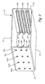
- FIG. 3 is a schematic perspective view of the housing of FIG. 1 .
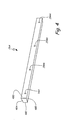
- FIG. 4 is a schematic perspective view of a tapered locking rail of FIG. 1 .
- FIG. 1 is a schematic view of assembly 10 including printed circuit boards (PCBs) 12A-12C connected to housing 14 via connecting mechanisms 16A-16F.
- PCBs 12A-12C can be virtually any kind of printed circuit board, such as polyimide boards used as engine controllers and diagnostic units in an aircraft electronics rack.
- PCBs 12A-12C can produce a relatively large amount of heat and benefit from that heat being conducted away.
- Housing 14 has sidewalls 18, 20, 22, and 24. Sidewall 18 is opposite and substantially parallel to sidewall 20. Sidewall 22 is opposite and substantially parallel to sidewall 24. Sidewall 22 and sidewall 24 each connect sidewall 18 to sidewall 20 so as to form a shape substantially that of a rectangular tube.
- housing 14 can be integrally formed and made by extrusion of aluminum. In other embodiments, housing 14 can be cast or machined and can be made of another suitable heat-conducting material.
- Connecting mechanisms 16A-16F include locking rails 26A-26F positioned in channels 28A-28F. Locking rails 26A-26F are attached to sidewalls 18 and 20 of housing 14 by connectors 30A-30F, respectively. Locking rails 26A-26F can be aluminum or other suitable heat-conducting material and can be extruded, cast, or machined. Connecting mechanisms 16A-16F can hold PCBs 12A-12C firmly in place and allow heat produced by PCBs 12A-12C to be conducted to housing 14. Thus, housing 14 can act as a heat sink.
- FIG. 2 is an enlarged view, taken from FIG. 1 , of connecting mechanism 16A connecting PCB 12A to housing 14. Though FIG. 2 shows only connecting mechanism 16A, the following description is equally applicably to connecting mechanisms 16B-16F (shown in FIG. 1 ). In the illustrated embodiment, connecting mechanisms 16B and 16C are substantially identical to connecting mechanism 16A, and connecting mechanisms 16D-16F are substantially identical mirror images of connecting mechanism 16A.
- Channel 28A is defined by guiderails 38 and 40, which extend, and protrude, from sidewall 18 toward sidewall 20 (shown in FIG. 1 ).
- Guiderails 38 and 40 can be integrally formed with sidewall 18.
- guiderail 38 tapers from its base 42A to its distal edge 42B.
- Guiderail 38 has surface 44A substantially perpendicular to sidewall 18 and has surface 44B not perpendicular with respect to sidewall 18.
- Guiderail 40 has surfaces 46A and 46B, both substantially perpendicular to sidewall 18.
- Locking rail 26A is positioned between guiderails 38 and 40.
- Locking rail 26A has surface 48A facing and engaging guiderail 38, surface 48B facing guiderail 40, surface 48C facing sidewall 18, and surface 48D facing sidewall 20.
- Surface 48B is substantially parallel to surface 44A, surface 46A, surface 46B, and PCB 12A, which are all substantially perpendicular to sidewall 18.
- Surface 48C is shorter than surface 48D such that locking rail 26A tapers from surface 48D to surface 48C.
- Surfaces 48A and 44B are inclined mating surfaces and are substantially parallel so as to facilitate sliding between locking rail 26A and guiderail 38.
- Surface 48A can be inclined with respect to surface 48B by an angle of between about 5 degrees to 30 degrees.
- Surface 44B can be inclined with respect to surface 44A by an angle of between about 5 degrees to 30 degrees.
- surfaces 48A and 44B can both be angled with respect to sidewall 18 by between about 60 degrees to 85 degrees.
- Surfaces 44B and 48A can be referred to as "beveled" surfaces.
- connector 30A is a threaded fastener such as a screw or bolt.
- connector 30A can be another type of connector suitable for attaching locking rail 26A to sidewall 18.
- Connector 30A extends through washer 50A, through hole 52A in sidewall 18, and into hole 54A in locking rail 26A.
- Connector 30A can be threadedly engaged with hole 54A such that locking rail 26A is forced laterally toward sidewall 18 as connector 30A is tightened.
- the angled incline of surface 48A and surface 48B forces locking rail 26A toward PCB 12A and guiderail 40.
- PCB 12A is positioned between surface 48B of locking rail 26A and surface 46A of guiderail 40.
- Locking rail 26A can, therefore, be tightened both against guiderail 38 of housing 14 and against an edge portion 56 of PCB 12A.
- the tapered incline of locking rail 26A causes locking rail 26A to clamp PCB 12A between locking rail 26A and guiderail 40 of mounting channel 28A in response to connector 30A forcing locking rail 26A laterally toward sidewall 18.
- hole 52A has a larger diameter than that of hole 54A.
- Hole 52A is large enough to allow connector 30A to slide in a direction from guiderail 38 toward guiderail 40 as connector 30A tightens locking rail 26A.
- FIG. 3 is a schematic perspective view showing housing 14 and locking rails 26D-26F.
- connector 30A is grouped with three other connectors 130A, 230A, and 330A for attaching locking rail 26A (shown in FIGS. 1 and 2 ) to sidewall 18.
- Connectors 30A, 130A, 230A, and 330A are spaced along a length of sidewall 18 and locking rail 26A.
- locking rail 26A can provide substantially even pressure on PCB 12A (shown in FIG. 1 ) along the length of locking rail 26A to encourage good contact for heat transfer purposes.
- locking rails 26B-26F are also attached to housing 14 with a plurality of connectors.
- FIG. 4 is a schematic perspective view of locking rail 26A. Though FIG. 4 shows only locking rail 26A, the following description is equally applicably to locking rails 26B-26F (shown in FIG. 1 ). FIG. 4 shows the shape of locking rail 26A in greater detail, as well as positioning of holes 54A, 154A, 254A, and 354A.
- locking rail 26A is a hexahedron with surfaces 48C and 48D being parallel and surfaces 48A and 48B being inclined.
- Locking rail 26A can be integrally formed as a single piece. Holes 54A, 154A, 254A, and 354A can extend from surface 48C to and through surface 48D.
- Assembly 10 offers numerous benefits and advantages. For example, the various surfaces being angled as described allows for connecting mechanisms 16A-16F to hold PCBs 12A-12C firmly to housing 14 by forcing locking rails 26A-26F laterally toward one of sidewall 18 or sidewall 20. This allows the respective connectors to be positioned in a way that facilitates ease of assembly. Also, by forming each locking rails 26A-26F integrally and forming housing 14 integrally, assembly 10 can be relatively simple, inexpensive, low weight, and reliable. Assembly 10 can be particularly useful in aerospace applications but may be used in other applications as well.
Landscapes
- Engineering & Computer Science (AREA)
- Microelectronics & Electronic Packaging (AREA)
- Mounting Of Printed Circuit Boards And The Like (AREA)
Abstract
An assembly includes a housing (14), a first locking rail (26A), and a second locking rail (26D). The housing has first and second sidewalls (18,20). First and second guiderails (38,40) on the first sidewall (18). Third and fourth guiderails on the second sidewall (20). The first locking rail is positioned between the first guiderail and the second guiderail. The first locking rail has a first surface (44B) nearest the first guiderail and a second surface (48B) nearest the second guiderail. The first surface is inclined with respect to the second surface. The second locking rail is positioned between the third guiderail and the fourth guiderail. The second locking rail has a third surface nearest the third guiderail and a fourth surface nearest the fourth guiderail. The third surface is inclined with respect to the fourth surface.
Description
- The present invention relates to a housing for a printed circuit board (PCB), and in particular, to mounting a PCB to its housing. In certain applications, one or more printed circuit boards are attached between two walls of a housing. Each wall typically has a channel into which the PCB is slid and clamped in place by a rather complicated wedge lock system. A conventional wedge lock system includes several trapezoidal wedges aligned end-to-end and connected to one another via a bolt extending through holes in each wedge. The bolt applies a longitudinal compressive force on the trapezoidal wedges forcing each adjacent trapezoidal wedge laterally in opposite directions. When such a wedge lock system is placed in the channels with the PCB, tightening the bolt provides a compressive force against the PCB and the channel, thus holding the PCB in place. Housings that utilize these conventional wedge lock systems can be relatively complicated, heavy, and expensive.
- According to one embodiment of the present invention, an assembly includes a housing, a first locking rail, and a second locking rail. The housing has first and second sidewalls. First and second guiderails extend from the first sidewall toward the second sidewall. Third and fourth guiderails extend from the second sidewall toward the first sidewall. The first locking rail is positioned between the first guiderail and the second guiderail. The first locking rail has a first surface nearest the first guiderail and a second surface nearest the second guiderail. The first surface is inclined with respect to the second surface. The second locking rail is positioned between the third guiderail and the fourth guiderail. The second locking rail has a third surface nearest the third guiderail and a fourth surface nearest the fourth guiderail. The third surface is inclined with respect to the fourth surface.
- Another embodiment of the present invention is a method for mounting a printed circuit board to a housing. The method includes positioning a printed circuit board (PCB) in a housing with a first edge portion of the PCB within a first mounting channel on a first sidewall of the housing and a second edge portion of the PCB within a second mounting channel on a second sidewall of the housing, positioning a first tapered locking rail in the first mounting channel and a second tapered locking rail in the second mounting channel, attaching the first tapered locking rail to the first sidewall with a first connector and the second tapered locking rail to the second sidewall with a second connector, and tightening the first and second connectors so as to clamp the PCB between the first tapered locking rail and the first mounting channel and between the second tapered locking rail and the second mounting channel.
-
FIG. 1 is a schematic view of printed circuit boards (PCBs) connected to a housing with tapered locking rails. -
FIG. 2 is an enlarged view, taken fromFIG. 1 , of a connecting mechanism for connecting a PCB to the housing. -
FIG. 3 is a schematic perspective view of the housing ofFIG. 1 . -
FIG. 4 is a schematic perspective view of a tapered locking rail ofFIG. 1 . -
FIG. 1 is a schematic view ofassembly 10 including printed circuit boards (PCBs) 12A-12C connected tohousing 14 via connectingmechanisms 16A-16F. PCBs 12A-12C can be virtually any kind of printed circuit board, such as polyimide boards used as engine controllers and diagnostic units in an aircraft electronics rack. PCBs 12A-12C can produce a relatively large amount of heat and benefit from that heat being conducted away. -
Housing 14 hassidewalls Sidewall 18 is opposite and substantially parallel tosidewall 20.Sidewall 22 is opposite and substantially parallel tosidewall 24.Sidewall 22 andsidewall 24 each connectsidewall 18 tosidewall 20 so as to form a shape substantially that of a rectangular tube. In one embodiment,housing 14 can be integrally formed and made by extrusion of aluminum. In other embodiments,housing 14 can be cast or machined and can be made of another suitable heat-conducting material. -
Connecting mechanisms 16A-16F includelocking rails 26A-26F positioned inchannels 28A-28F.Locking rails 26A-26F are attached tosidewalls housing 14 byconnectors 30A-30F, respectively.Locking rails 26A-26F can be aluminum or other suitable heat-conducting material and can be extruded, cast, or machined.Connecting mechanisms 16A-16F can holdPCBs 12A-12C firmly in place and allow heat produced byPCBs 12A-12C to be conducted to housing 14. Thus,housing 14 can act as a heat sink. -
FIG. 2 is an enlarged view, taken fromFIG. 1 , of connectingmechanism 16A connecting PCB 12A tohousing 14. ThoughFIG. 2 shows only connectingmechanism 16A, the following description is equally applicably to connectingmechanisms 16B-16F (shown inFIG. 1 ). In the illustrated embodiment, connectingmechanisms mechanism 16A, and connectingmechanisms 16D-16F are substantially identical mirror images ofconnecting mechanism 16A. -
Channel 28A is defined byguiderails sidewall 18 toward sidewall 20 (shown inFIG. 1 ).Guiderails sidewall 18. In the illustrated embodiment,guiderail 38 tapers from itsbase 42A to itsdistal edge 42B. Guiderail 38 hassurface 44A substantially perpendicular tosidewall 18 and hassurface 44B not perpendicular with respect tosidewall 18. Guiderail 40 hassurfaces sidewall 18. -
Locking rail 26A is positioned betweenguiderails Locking rail 26A hassurface 48A facing and engagingguiderail 38,surface 48B facing guiderail 40,surface 48C facing sidewall 18, andsurface 48D facing sidewall 20.Surface 48B is substantially parallel tosurface 44A,surface 46A,surface 46B, andPCB 12A, which are all substantially perpendicular tosidewall 18.Surface 48C is shorter thansurface 48D such thatlocking rail 26A tapers fromsurface 48D tosurface 48C.Surfaces locking rail 26A andguiderail 38.Surface 48A can be inclined with respect tosurface 48B by an angle of between about 5 degrees to 30 degrees.Surface 44B can be inclined with respect tosurface 44A by an angle of between about 5 degrees to 30 degrees. Thus,surfaces sidewall 18 by between about 60 degrees to 85 degrees.Surfaces - In the illustrated embodiment,
connector 30A is a threaded fastener such as a screw or bolt. In alternative embodiments,connector 30A can be another type of connector suitable for attachinglocking rail 26A tosidewall 18.Connector 30A extends throughwasher 50A, throughhole 52A insidewall 18, and intohole 54A inlocking rail 26A.Connector 30A can be threadedly engaged withhole 54A such thatlocking rail 26A is forced laterally towardsidewall 18 asconnector 30A is tightened. Aslocking rail 26A is forced towardsidewall 18, the angled incline ofsurface 48A andsurface 48Bforces locking rail 26A toward PCB 12A andguiderail 40. PCB 12A is positioned betweensurface 48B oflocking rail 26A andsurface 46A ofguiderail 40.Locking rail 26A can, therefore, be tightened both againstguiderail 38 ofhousing 14 and against anedge portion 56 of PCB 12A. Thus, the tapered incline of lockingrail 26A causes lockingrail 26A to clampPCB 12A between lockingrail 26A andguiderail 40 of mountingchannel 28A in response toconnector 30A forcing lockingrail 26A laterally towardsidewall 18. - In the illustrated embodiment,
hole 52A has a larger diameter than that ofhole 54A.Hole 52A is large enough to allowconnector 30A to slide in a direction fromguiderail 38 towardguiderail 40 asconnector 30A tightens lockingrail 26A. -
FIG. 3 is a schematic perspectiveview showing housing 14 and lockingrails 26D-26F. In the embodiment illustrated inFIG. 3 ,connector 30A is grouped with threeother connectors rail 26A (shown inFIGS. 1 and2 ) tosidewall 18.Connectors sidewall 18 and lockingrail 26A. Thus, lockingrail 26A can provide substantially even pressure onPCB 12A (shown inFIG. 1 ) along the length of lockingrail 26A to encourage good contact for heat transfer purposes. Similarly, lockingrails 26B-26F are also attached tohousing 14 with a plurality of connectors. -
FIG. 4 is a schematic perspective view of lockingrail 26A. ThoughFIG. 4 shows only lockingrail 26A, the following description is equally applicably to lockingrails 26B-26F (shown inFIG. 1 ).FIG. 4 shows the shape of lockingrail 26A in greater detail, as well as positioning ofholes rail 26A is a hexahedron withsurfaces surfaces rail 26A can be integrally formed as a single piece.Holes surface 48C to and throughsurface 48D. -
Assembly 10 offers numerous benefits and advantages. For example, the various surfaces being angled as described allows for connectingmechanisms 16A-16F to holdPCBs 12A-12C firmly tohousing 14 by forcing locking rails 26A-26F laterally toward one ofsidewall 18 orsidewall 20. This allows the respective connectors to be positioned in a way that facilitates ease of assembly. Also, by forming each locking rails 26A-26F integrally and forminghousing 14 integrally,assembly 10 can be relatively simple, inexpensive, low weight, and reliable.Assembly 10 can be particularly useful in aerospace applications but may be used in other applications as well. - While the invention has been described with reference to exemplary embodiment, it will be understood by those skilled in the art that various changes may be made and equivalents may be substituted for elements thereof without departing from the scope of the invention. In addition, many modifications may be made to adapt a particular situation or material to the teachings of the invention without departing from the essential scope thereof. Therefore, it is intended that the invention not be limited to the particular embodiments disclosed, but that the invention will include all embodiments falling within the scope of the appended claims. For example, not all surfaces need to be perpendicular, parallel, and/or angled precisely as illustrated but may be modified as suitable for a particular application.
Claims (15)
- A printed circuit board (PCB) mounting assembly comprising:a housing (14) having a first sidewall (18) with a first mounting channel (28A) with first and second opposed surfaces (44B,46A) and a second sidewall (20) with a second mounting channel (28D) with first and second opposed surfaces;first and second locking rails (26A,26D) positioned in the first and second mounting channels, respectively;a space between the first locking rail and the second wall of the first mounting channel and also between the second locking rail and the second wall of the second mounting channel for positioning a PCB; andfirst and second connectors (30A,30D) attaching the first and second locking rails to the first and second sidewalls, respectively, wherein the first locking rail is tapered so as to be arranged to clamp the PCB between the first locking rail and the second wall of the first mounting channel in response to the first connector forcing the first locking rail laterally toward the first sidewall, and wherein the second locking rail is tapered so as to be arranged to clamp the PCB between the second locking rail and the second wall of the second mounting channel in response to the second connector forcing the second locking rail laterally toward the second sidewall.
- The PCB mounting assembly of claim 1, wherein the first connector (30A) extends through a first hole (52A) in the first sidewall (18) and into a second hole (54A) in the first locking rail (26A), and wherein the second connector (30D) extends through a third hole in the second sidewall (20) and into a fourth hole in the second locking rail.
- The PCB mounting assembly of claim 2, wherein tightening the first and second connectors (30A,30D) tightens the first and second locking rails (26A,26D) against both the housing (14) and the PCB (12A).
- The PCB mounting assembly of claim 2 or 3, wherein the first hole (52A) has a larger diameter than that of the second hole (54A) and the third hole has a larger diameter than that of the fourth hole, and wherein the first connector (30A) is preferably threadedly engaged with the second hole (54A) and the second connector (30D) is preferably threadedly engaged with the fourth hole.
- The PCB mounting assembly of any preceding claim, wherein the first connector (30A) is one of a plurality of screws attaching the first locking rail (26A) to the first sidewall (18), and wherein the second connector (30D) is one of a plurality of screws attaching the second locking rail (26D) to the second sidewall.
- The PCB mounting assembly of any preceding claim, wherein the first locking rail is integrally formed as a single piece and the second locking rail is integrally formed as a single piece.
- The PCB mounting assembly of any preceding claim, wherein the housing (14) is made of extruded aluminum, and wherein the first and second locking rails (26A,26D) are preferably made of aluminum.
- The PCT mounting assembly of any preceding claim, wherein:the first mounting channel (28A) is formed by first and second guiderails (38,40) which extend from the first sidewall (18) toward the second sidewall (20);wherein the second mounting channel (28D) is formed by third and fourth guiderails which extend from the second sidewall (20) toward the first sidewall (18);
wherein the first locking rail (26A) has a first surface (48A) nearest the first guiderail (38) and a second surface (48B) nearest the second guiderail (40), and wherein the first surface is inclined with respect to the second surface; and
wherein a second locking rail (26D) is positioned between the third guiderail and the fourth guiderail, wherein the second locking rail has a third surface nearest the third guiderail and a fourth surface nearest the fourth guiderail, and wherein the third surface is inclined with respect to the fourth surface. - The assembly of claim 8, wherein a surface of the first guiderail (38), which is the first surface (44b) of the first channel (28A), facing the first surface (48A) of the locking rail (26A) is substantially parallel to the first surface for mating with the first surface, and wherein a surface of the third guiderail, which is the first surface of the second channel (28D), facing the third surface is substantially parallel to the third surface for mating with the third surface.
- The assembly of claim 9, wherein the first surface (48A) of the first locking rail (26A) is angled with respect to the second surface (48B) of the first locking rail (26A) by between about 5 degrees to 30 degrees, and wherein the third surface of the second locking rail (26D) is angled with respect to the fourth surface of the second locking rail by between about 5 degrees to 30 degrees, and wherein the surface (44B) of the first guiderail (38) facing the first locking rail is (28A) preferably angled with respect to a surface (46A) of the second guiderail (40) facing the first locking rail by between about 5 degrees to 30 degrees, and wherein a surface of the third guiderail facing the second locking rail (28D) is preferably angled with respect to a surface of the fourth guiderail facing the second locking rail by between about 5 degrees to 30 degrees.
- The assembly of claim 8, 9 or 10, wherein the first guiderail (38) tapers from its base (42A) to its distal edge (42B) and the third guiderail tapers from its base to its distal edge.
- The assembly of any one of claims 8 to 11, wherein the housing (14) further includes a third sidewall (22) and a fourth sidewall (24), both connecting the first sidewall (18) to the second sidewall (20), and wherein the first sidewall, second sidewall, third sidewall, fourth sidewall, first guiderail, second guiderail, third guiderail, and fourth guiderail are preferably integrally formed.
- A method for mounting a printed circuit board (12A) to a housing (14), the method comprising:positioning the printed circuit board (PCB) in the housing with a first edge portion of the PCB within a first mounting channel (28A) on a first sidewall (18) of the housing and a second edge portion of the PCB within a second mounting channel on a second sidewall (20) of the housing;positioning a first tapered locking rail (26A) in the first mounting channel and a second tapered locking rail (26D) in the second mounting channel;attaching the first tapered locking rail to the first sidewall with a first connector (30A) and the second tapered locking rail to the second sidewall with a second connector (30B); andtightening the first and second connectors so as to clamp the PCB between the first tapered locking rail and a wall of the first mounting channel and between the second tapered locking rail and a wall of the second mounting channel.
- The method of claim 13, wherein tightening the first connector (30A) forces the first tapered locking rail (26A) toward the PCB (12B) and toward the first sidewall (18), and wherein tightening the second connector (30D) forces the second tapered locking rail (26D) toward the PCB and toward the second sidewall (20)
the method preferably further comprising:inserting the first connector (30A) through a first hole (52A) in the first sidewall (18) and into a second hole (54A) in the first tapered locking rail (26A); andinserting the second connector (30D) through a third hole in the second sidewall (20) and into a fourth hole in the second tapered locking rail (26D). - The assembly of claim 13 or 14, wherein the housing (14) is aluminum and made by extrusion.
Applications Claiming Priority (1)
| Application Number | Priority Date | Filing Date | Title |
|---|---|---|---|
| US12/870,397 US20120051014A1 (en) | 2010-08-27 | 2010-08-27 | Printed circuit board housing with tapered locking rails |
Publications (1)
| Publication Number | Publication Date |
|---|---|
| EP2424341A1 true EP2424341A1 (en) | 2012-02-29 |
Family
ID=44913174
Family Applications (1)
| Application Number | Title | Priority Date | Filing Date |
|---|---|---|---|
| EP11176061A Withdrawn EP2424341A1 (en) | 2010-08-27 | 2011-07-29 | Printed circuit board housing with tapered locking rails |
Country Status (2)
| Country | Link |
|---|---|
| US (1) | US20120051014A1 (en) |
| EP (1) | EP2424341A1 (en) |
Cited By (1)
| Publication number | Priority date | Publication date | Assignee | Title |
|---|---|---|---|---|
| EP3890462A1 (en) * | 2020-04-01 | 2021-10-06 | Hamilton Sundstrand Corporation | Wedge lock support columns in electronic chassis |
Families Citing this family (3)
| Publication number | Priority date | Publication date | Assignee | Title |
|---|---|---|---|---|
| CN103874381A (en) * | 2012-12-18 | 2014-06-18 | 鸿富锦精密工业(深圳)有限公司 | Circuit board fixing device |
| US10020641B1 (en) * | 2016-12-22 | 2018-07-10 | Hamilton Sundstrand Corporation | Resistance-limited electrical interconnects |
| CN120711674B (en) * | 2025-08-28 | 2025-10-31 | 北京电擎科技有限公司 | Motor controller control panel plug structure |
Citations (3)
| Publication number | Priority date | Publication date | Assignee | Title |
|---|---|---|---|---|
| EP0456022A1 (en) * | 1990-05-09 | 1991-11-13 | Hughes Aircraft Company | Printed circuit board edge-locking device |
| US5954122A (en) * | 1998-07-09 | 1999-09-21 | Eastman Kodak Company | Wedge clamping device for a flat plate/printed circuit board |
| US20070211442A1 (en) * | 2005-05-19 | 2007-09-13 | Miller Richard D | High Density Card Retention Device |
Family Cites Families (16)
| Publication number | Priority date | Publication date | Assignee | Title |
|---|---|---|---|---|
| US1787090A (en) * | 1929-08-05 | 1930-12-30 | Richard T Scholes | Rail joint |
| US1833666A (en) * | 1930-05-26 | 1931-11-24 | John E Watson | Heat exchanger |
| US2213402A (en) * | 1937-08-23 | 1940-09-03 | Libbey Owens Ford Glass Co | Division, corner, and reverse bar |
| US2747703A (en) * | 1952-03-29 | 1956-05-29 | Smith Corp A O | Wall panel construction |
| US2869210A (en) * | 1955-04-18 | 1959-01-20 | Plan Hold Corp | Friction-type binder |
| US3119331A (en) * | 1961-08-10 | 1964-01-28 | Roland Offsetmaschf | Clamping device for clamping printing plates of printing machines |
| US3307699A (en) * | 1964-04-17 | 1967-03-07 | Barber Greene Co | Screen tensioning device |
| US4525770A (en) * | 1984-04-02 | 1985-06-25 | United Technologies Corporation | Clamping circuit board guides |
| EP0228989A1 (en) * | 1985-12-17 | 1987-07-15 | GebràDer Sulzer Aktiengesellschaft | Loom |
| US5057968A (en) * | 1989-10-16 | 1991-10-15 | Lockheed Corporation | Cooling system for electronic modules |
| SE9101690D0 (en) * | 1991-06-04 | 1991-06-04 | Mircona Ab | DEVICE FOR TOOL MACHINERY |
| US6434905B1 (en) * | 2000-08-02 | 2002-08-20 | C. R. Laurence Co., Inc. | Door rail system |
| US6639801B2 (en) * | 2001-08-10 | 2003-10-28 | Agilent Technologies, Inc. | Mechanical packaging architecture for heat dissipation |
| US7405928B2 (en) * | 2004-05-03 | 2008-07-29 | Hewlett-Packard Development Company, L.P. | Removable information storage device enclosure |
| US7193850B2 (en) * | 2004-08-31 | 2007-03-20 | Hamilton Sundstrand Corporation | Integrated heat removal and vibration damping for avionic equipment |
| US8477498B2 (en) * | 2010-03-25 | 2013-07-02 | Curtiss-Wright Controls, Inc. | Conduction-cooled apparatus and methods of forming said apparatus |
-
2010
- 2010-08-27 US US12/870,397 patent/US20120051014A1/en not_active Abandoned
-
2011
- 2011-07-29 EP EP11176061A patent/EP2424341A1/en not_active Withdrawn
Patent Citations (3)
| Publication number | Priority date | Publication date | Assignee | Title |
|---|---|---|---|---|
| EP0456022A1 (en) * | 1990-05-09 | 1991-11-13 | Hughes Aircraft Company | Printed circuit board edge-locking device |
| US5954122A (en) * | 1998-07-09 | 1999-09-21 | Eastman Kodak Company | Wedge clamping device for a flat plate/printed circuit board |
| US20070211442A1 (en) * | 2005-05-19 | 2007-09-13 | Miller Richard D | High Density Card Retention Device |
Cited By (2)
| Publication number | Priority date | Publication date | Assignee | Title |
|---|---|---|---|---|
| EP3890462A1 (en) * | 2020-04-01 | 2021-10-06 | Hamilton Sundstrand Corporation | Wedge lock support columns in electronic chassis |
| US11997815B2 (en) | 2020-04-01 | 2024-05-28 | Hamilton Sundstrand Corporation | Wedge lock support columns in electronic chassis |
Also Published As
| Publication number | Publication date |
|---|---|
| US20120051014A1 (en) | 2012-03-01 |
Similar Documents
| Publication | Publication Date | Title |
|---|---|---|
| US8456846B2 (en) | Wedge based circuit board retainer | |
| US20050191149A1 (en) | Fastener for variable mounting | |
| US4994937A (en) | Hydraulic thermal clamp for electronic modules | |
| US7349221B2 (en) | Device for increased thermal conductivity between a printed wiring assembly and a chassis | |
| EP3582597B1 (en) | Systems and methods for heatsink to rail thermal interface enhancement | |
| US6285564B1 (en) | Circuit card retainer assembly | |
| US7483271B2 (en) | High density card retention device | |
| EP1853097A2 (en) | Wedgelock device for increased thermal conductivity of a printed wiring assembly | |
| EP2403075A2 (en) | Connector for interconnecting conductors of circuit boards | |
| US20160100505A1 (en) | Device with heat transfer portion | |
| JP2002057477A (en) | Basic rack | |
| CN1806478A (en) | Mounting plate for electronic components | |
| EP0480865A1 (en) | Printed circuit board mounting apparatus | |
| US20120051014A1 (en) | Printed circuit board housing with tapered locking rails | |
| US20260107372A1 (en) | Electronic assemblies having embedded passive heat pipes and associated method | |
| US7477524B2 (en) | Retainer and method for holding a circuit card against a clamping surface of a chassis or heatsink | |
| RU2367126C2 (en) | Circuit board for electronic structural components | |
| EP3832808B1 (en) | Modular fixing system and method thereof | |
| US12610490B2 (en) | Wedge based circuit board retainer with dual end drivescrew | |
| CN111867307B (en) | Fixing buckle | |
| EP0289686A1 (en) | Spring loaded multi-wedge card retainer | |
| US7046506B2 (en) | Circuit board card guide and lock | |
| US20080037231A1 (en) | Heat Transferring Guide for Electronic Cards |
Legal Events
| Date | Code | Title | Description |
|---|---|---|---|
| AK | Designated contracting states |
Kind code of ref document: A1 Designated state(s): AL AT BE BG CH CY CZ DE DK EE ES FI FR GB GR HR HU IE IS IT LI LT LU LV MC MK MT NL NO PL PT RO RS SE SI SK SM TR |
|
| AX | Request for extension of the european patent |
Extension state: BA ME |
|
| PUAI | Public reference made under article 153(3) epc to a published international application that has entered the european phase |
Free format text: ORIGINAL CODE: 0009012 |
|
| STAA | Information on the status of an ep patent application or granted ep patent |
Free format text: STATUS: THE APPLICATION IS DEEMED TO BE WITHDRAWN |
|
| 18D | Application deemed to be withdrawn |
Effective date: 20120830 |