EP2424058A1 - Procede de gestion de la contraction thermique d'un cable supraconducteur et agencement pour la mise en oeuvre de ce procede - Google Patents
Procede de gestion de la contraction thermique d'un cable supraconducteur et agencement pour la mise en oeuvre de ce procede Download PDFInfo
- Publication number
- EP2424058A1 EP2424058A1 EP11177087A EP11177087A EP2424058A1 EP 2424058 A1 EP2424058 A1 EP 2424058A1 EP 11177087 A EP11177087 A EP 11177087A EP 11177087 A EP11177087 A EP 11177087A EP 2424058 A1 EP2424058 A1 EP 2424058A1
- Authority
- EP
- European Patent Office
- Prior art keywords
- cable
- screen
- ring
- locking
- blocking
- Prior art date
- Legal status (The legal status is an assumption and is not a legal conclusion. Google has not performed a legal analysis and makes no representation as to the accuracy of the status listed.)
- Granted
Links
Images




Classifications
-
- H—ELECTRICITY
- H02—GENERATION; CONVERSION OR DISTRIBUTION OF ELECTRIC POWER
- H02G—INSTALLATION OF ELECTRIC CABLES OR LINES, OR OF COMBINED OPTICAL AND ELECTRIC CABLES OR LINES
- H02G15/00—Cable fittings
- H02G15/34—Cable fittings for cryogenic cables
-
- H—ELECTRICITY
- H01—ELECTRIC ELEMENTS
- H01B—CABLES; CONDUCTORS; INSULATORS; SELECTION OF MATERIALS FOR THEIR CONDUCTIVE, INSULATING OR DIELECTRIC PROPERTIES
- H01B12/00—Superconductive or hyperconductive conductors, cables, or transmission lines
- H01B12/02—Superconductive or hyperconductive conductors, cables, or transmission lines characterised by their form
-
- H—ELECTRICITY
- H01—ELECTRIC ELEMENTS
- H01B—CABLES; CONDUCTORS; INSULATORS; SELECTION OF MATERIALS FOR THEIR CONDUCTIVE, INSULATING OR DIELECTRIC PROPERTIES
- H01B12/00—Superconductive or hyperconductive conductors, cables, or transmission lines
- H01B12/14—Superconductive or hyperconductive conductors, cables, or transmission lines characterised by the disposition of thermal insulation
-
- H—ELECTRICITY
- H01—ELECTRIC ELEMENTS
- H01B—CABLES; CONDUCTORS; INSULATORS; SELECTION OF MATERIALS FOR THEIR CONDUCTIVE, INSULATING OR DIELECTRIC PROPERTIES
- H01B13/00—Apparatus or processes specially adapted for manufacturing conductors or cables
-
- H—ELECTRICITY
- H01—ELECTRIC ELEMENTS
- H01B—CABLES; CONDUCTORS; INSULATORS; SELECTION OF MATERIALS FOR THEIR CONDUCTIVE, INSULATING OR DIELECTRIC PROPERTIES
- H01B17/00—Insulators or insulating bodies characterised by their form
- H01B17/38—Fittings, e.g. caps; Fastenings therefor
-
- H—ELECTRICITY
- H01—ELECTRIC ELEMENTS
- H01R—ELECTRICALLY-CONDUCTIVE CONNECTIONS; STRUCTURAL ASSOCIATIONS OF A PLURALITY OF MUTUALLY-INSULATED ELECTRICAL CONNECTING ELEMENTS; COUPLING DEVICES; CURRENT COLLECTORS
- H01R4/00—Electrically-conductive connections between two or more conductive members in direct contact, i.e. touching one another; Means for effecting or maintaining such contact; Electrically-conductive connections having two or more spaced connecting locations for conductors and using contact members penetrating insulation
- H01R4/58—Electrically-conductive connections between two or more conductive members in direct contact, i.e. touching one another; Means for effecting or maintaining such contact; Electrically-conductive connections having two or more spaced connecting locations for conductors and using contact members penetrating insulation characterised by the form or material of the contacting members
- H01R4/68—Connections to or between superconductive connectors
-
- H—ELECTRICITY
- H02—GENERATION; CONVERSION OR DISTRIBUTION OF ELECTRIC POWER
- H02G—INSTALLATION OF ELECTRIC CABLES OR LINES, OR OF COMBINED OPTICAL AND ELECTRIC CABLES OR LINES
- H02G15/00—Cable fittings
- H02G15/007—Devices for relieving mechanical stress
-
- H—ELECTRICITY
- H10—SEMICONDUCTOR DEVICES; ELECTRIC SOLID-STATE DEVICES NOT OTHERWISE PROVIDED FOR
- H10N—ELECTRIC SOLID-STATE DEVICES NOT OTHERWISE PROVIDED FOR
- H10N60/00—Superconducting devices
- H10N60/80—Constructional details
- H10N60/81—Containers; Mountings
-
- Y—GENERAL TAGGING OF NEW TECHNOLOGICAL DEVELOPMENTS; GENERAL TAGGING OF CROSS-SECTIONAL TECHNOLOGIES SPANNING OVER SEVERAL SECTIONS OF THE IPC; TECHNICAL SUBJECTS COVERED BY FORMER USPC CROSS-REFERENCE ART COLLECTIONS [XRACs] AND DIGESTS
- Y02—TECHNOLOGIES OR APPLICATIONS FOR MITIGATION OR ADAPTATION AGAINST CLIMATE CHANGE
- Y02E—REDUCTION OF GREENHOUSE GAS [GHG] EMISSIONS, RELATED TO ENERGY GENERATION, TRANSMISSION OR DISTRIBUTION
- Y02E40/00—Technologies for an efficient electrical power generation, transmission or distribution
- Y02E40/60—Superconducting electric elements or equipment; Power systems integrating superconducting elements or equipment
-
- Y—GENERAL TAGGING OF NEW TECHNOLOGICAL DEVELOPMENTS; GENERAL TAGGING OF CROSS-SECTIONAL TECHNOLOGIES SPANNING OVER SEVERAL SECTIONS OF THE IPC; TECHNICAL SUBJECTS COVERED BY FORMER USPC CROSS-REFERENCE ART COLLECTIONS [XRACs] AND DIGESTS
- Y10—TECHNICAL SUBJECTS COVERED BY FORMER USPC
- Y10T—TECHNICAL SUBJECTS COVERED BY FORMER US CLASSIFICATION
- Y10T29/00—Metal working
- Y10T29/49—Method of mechanical manufacture
- Y10T29/49002—Electrical device making
- Y10T29/49014—Superconductor
Definitions
- the invention relates to a method for managing the thermal contraction of a superconducting cable and an arrangement for carrying out this method.
- a superconducting cable generally consists of a metal support such as copper, on which is wound a tape of superconducting material, itself covered with an insulator such as paper, and an external metal screen consisting of strips or wire, copper, for example.
- the entire support, ribbon and insulation is called cable body in the following.
- a high temperature superconducting cable is immersed in a cryogenic fluid to function properly. This cooling at a temperature of the order of -200 ° C causes a significant thermal contraction of the cable to be managed.
- the invention solves this problem and proposes a method for managing the thermal contraction of a superconducting cable comprising a cable body surrounded by an outer screen consisting of wound metal elements and installed between its ends in an enclosure filled with a cryogenic fluid, characterized in that it consists in mechanically applying a blocking force only requesting said screen in a said blocking place near said ends of the cable.
- the conductive elements wound in a certain pitch, forming the screen are mechanically resistant wires or bands which can therefore be tightened without any problem. It is either resistive elements for example copper, or metal elements of mechanical reinforcement.
- the resulting constant contraction force tends to tighten these rolled elements of the screen and reduce their winding pitch, between the two ends of the cable .
- the screen being blocked at the two locking locations, this pitch remains constant but it results in a radial pressure on all other elements or layers of the superconducting cable constituting the cable body, which blocks them as for them. Only a blocking of the screen is necessary, in order to avoid any longitudinal displacement due to the thermal contraction of the cable.
- the method consists in mechanically locking said screen between each of said ends of the cable and said enclosure.
- the method consists in mechanically blocking said screen in an additional cryostat module inserted between each of said ends of the cable and said enclosure.
- said blocking force is transmitted to a support device fixed to the ground or equivalent.
- the contraction between said locking point and the near end of the cable can be managed by a sliding contact.
- the invention also relates to a locking arrangement for the implementation of such a method, characterized in that it comprises a ring disposed under said screen at said locking position and two annular flanges of complementary internal shape arranged on both sides. other of the plane of symmetry of said ring and clamped to one another.
- Such a locking arrangement can hold a relatively high force of the order of several tons.
- said ring has a curved outer surface in the shape of a circular arc and said annular flanges have a complementary rounded internal shape.
- At least one of said flanges is secured to a support device fixed to the ground or equivalent.
- the invention finally relates to a method of setting up such an arrangement, characterized in that it consists in sliding said ring under said screen from the end of the cable to the blocking position and then to put in place said flanges.
- said ring is equipped with two removable external handles arranged between two adjacent conductive elements of the screen and is turned and slid to the locking position.
- Such a method does not affect the continuity of the cable screen and therefore does not require a specific connection of the screen.
- a line of a superconducting cable comprises an enclosure filled with a cryogenic fluid called cryostat 1 containing the cable 2 whose ends are arranged in a terminal 3A, 3B where the resistive metal support of the cable is connected to the outputs 4A, 4B .
- the cable 2 comprises an external screen consisting of metal elements, in the form of son or strips, wound to which is mechanically applied a locking force only urging the screen in a so-called blocking location 5A, 5B near the ends of the cable .
- This blocking force does not stress the cable body at the blocking point.
- the line may also comprise an additional cryostat module 6A, 6B disposed between the cryostat 1 and the terminations 3A, 3B.
- the method according to the invention consists in mechanically locking the screen between each of the ends of the cable 1 and the cryostat 1.
- These blocking locations may be arranged in the terminations 3A, 3B as illustrated in FIG. figure 1 or preferably in the additional cryostat modules 6A, 6B as illustrated in FIG. figure 2 .
- the locking force is transmitted to a support device 7A, 7B mechanically resistant and fixed to the ground or equivalent.
- the locking arrangement is secured to the chamber of the cryostat 1 or the additional cryostat module 6A, 6B and this enclosure is for its solidly secured to the ground.
- the contraction between the blocking position 5A, 5B and the near end of the cable can be managed by a sliding contact.
- FIGS. 3 to 5 show in vertical section embodiments of a blocking arrangement for the implementation of such a method.
- This locking arrangement comprises a ring 8 having a smooth external surface disposed beneath the screen 2A at the said locking point and two annular flanges 9, 10 of internal diameter slightly greater than the external diameter of the cable 1 and of complementary internal shape arranged on both sides. other of the plane of symmetry of the ring and tightened to one another, by means of a screwing assembly.
- This ring has an internal diameter slightly greater than the outer diameter of the cable off the screen 2A.
- the ring 8 has a curved outer surface in the shape of a circular arc and the annular flanges 9, 10 have a complementary rounded internal shape.
- This ring 8 is mechanically resistant material and has no specific electrical property. It is preferably made of stainless steel.
- the screwing assembly 11 may be unique and ensure the attachment of the two flanges 9, 10 together and also on the support device 12, as shown in FIG. figure 3 .
- Two screwing assemblies may also be provided, one 11 'ensuring the attachment of the two flanges 9, 10 together, and the other 11' ensuring the attachment of one of the flanges 9 to the support device 12, as illustrated in FIG. the figure 4 .
- the screwing assembly 11 may be single and ensure the fixing of the two flanges 9, 10 together, one of the flanges 9 being welded to the support device 12, as illustrated in FIG. figure 5 .
- one of the flanges 10 is threaded on the cable 2 at its end concerned and a portion of the screen 2A is removed at this end and the ring 8 is threaded therein. It comprises a set of orifices 8A whose function will be specified later.
- the ring 8 is slid partially under the screen 2A.
- two removable external handles 13A, 13B are introduced into two diametrically opposed orifices 8A. These handles are in the form of simple tie rods.
- the two removable external handles 13A, 13B are arranged between two adjacent conductive elements of the screen 2A and the ring 8 is slid under the screen of the end of the cable to the locking location by rotation and sliding according to arrow F following the pitch of these two conductive elements to the blocking position.
- the handles 13A, 13B are disassembled and the second flange 9 is then threaded onto the end of the cable.
- the two flanges 9, 10 are brought into abutment against the bulge formed by the ring 8 under the screen 2A.
- the screw assembly 11 consisting of a number of bolts is disposed in orifices carried by the flanges 9, 10 and clamps the two flanges against the ring 8 with the screen 2A interposed.
Landscapes
- Physics & Mathematics (AREA)
- Condensed Matter Physics & Semiconductors (AREA)
- General Physics & Mathematics (AREA)
- Engineering & Computer Science (AREA)
- Manufacturing & Machinery (AREA)
- Gas Or Oil Filled Cable Accessories (AREA)
- Superconductors And Manufacturing Methods Therefor (AREA)
- Containers, Films, And Cooling For Superconductive Devices (AREA)
Abstract
Description
- L'invention concerne un procédé de gestion de la contraction thermique d'un câble supraconducteur et un agencement pour la mise en oeuvre de ce procédé.
- Un câble supraconducteur se compose généralement d'un support métallique tel que du cuivre, sur lequel est enroulé un ruban en matériau supraconducteur, lui-même recouvert d'un isolant tel que du papier, et d'un écran métallique externe constitué de bandes ou de fils, de cuivre par exemple. L'ensemble du support, du ruban et de l'isolant est appelé corps de câble dans ce qui suit.
- Un câble supraconducteur à haute température est immergé dans un fluide cryogénique afin de fonctionner correctement. Ce refroidissement à une température de l'ordre de -200°C entraîne une contraction thermique significative du câble qui doit être gérée.
- Il est connu, par exemple du document de brevet
EP 1 489 692 , de gérer cette contraction au moyen d'un conducteur flexible raccordé à l'extrémité du câble ou au moyen de contacts glissants. - Ceci étant, il s'avère que ce type de solution n'est pas exploitable industriellement. En effet, la contraction est de l'ordre de 0,3 % de la longueur du câble et, sur des lignes de longueur égale à plusieurs kilomètres, elle atteint plusieurs mètres, ingérables ou difficilement gérables économiquement par des contacts glissants ou des conducteurs flexibles. Il serait nécessaire de plus de réaliser des ouvrages de génie civil additionnels correspondant encombrants, ce qui peut même être impossible compte-tenu de la place disponible.
- L'invention résout ce problème et propose un procédé de gestion de la contraction thermique d'un câble supraconducteur comportant un corps de câble entouré d'un écran externe constitué d'éléments métalliques enroulés et installé entre ses extrémités dans une enceinte remplie d'un fluide cryogénique, caractérisé en ce qu'il consiste à appliquer mécaniquement un effort de blocage sollicitant uniquement ledit écran en un endroit dit de blocage à proximité desdites extrémités du câble.
- Les éléments conducteurs enroulés selon un certain pas, formant l'écran, sont des fils ou des bandes résistantes mécaniquement qui peuvent donc être serrées sans problème. Il s'agit soit d'éléments résistifs par exemple en cuivre, soit d'éléments métalliques de renforcement mécanique.
- Lors du refroidissement d'un tel câble, la force de contraction résultante constante, et de l'ordre de plusieurs tonnes, tend à resserrer ces éléments enroulés de l'écran et à diminuer leur pas d'enroulement, entre les deux extrémités du câble. Selon l'invention, l'écran étant bloqué aux deux endroits de blocage, ce pas reste constant mais il en résulte une pression radiale sur tous les autres éléments ou couches du câble supraconducteur constituant le corps de câble, qui les bloque quant à eux. Seul un blocage de l'écran est donc nécessaire, afin d'éviter tout déplacement longitudinal dû à la contraction thermique du câble.
- Selon un mode de réalisation préféré, le procédé consiste à bloquer mécaniquement ledit écran entre chacune desdites extrémités du câble et ladite enceinte.
- Avantageusement, le procédé consiste à bloquer mécaniquement ledit écran dans un module de cryostat supplémentaire intercalé entre chacune desdites extrémités du câble et ladite enceinte.
- De préférence, ledit effort de blocage est transmis à un dispositif de support fixé au sol ou équivalent.
- La contraction entre ledit endroit de blocage et l'extrémité proche du câble peut être gérée par un contact glissant.
- L'invention concerne également un agencement de blocage pour la mise en oeuvre d'un tel procédé, caractérisé en ce qu'il comporte une bague disposée sous ledit écran audit endroit de blocage et deux brides annulaires de forme interne complémentaire disposées de part et d'autre du plan de symétrie de ladite bague et serrées l'une à l'autre.
- Un tel agencement de blocage peut tenir une force relativement élevée de l'ordre de plusieurs tonnes.
- Selon un mode de réalisation préféré, ladite bague a une surface externe bombée en forme d'arc de cercle et lesdites brides annulaires ont une forme interne arrondie complémentaire.
- De préférence, au moins l'une desdites brides est solidarisée à un dispositif de support fixé au sol ou équivalent.
- L'invention concerne enfin un procédé de mise en place d'un tel agencement, caractérisé en ce qu'il consiste à glisser ladite bague sous ledit écran de l'extrémité du câble jusqu'à l'endroit de blocage puis de mettre en place lesdites brides.
- De préférence, à l'extrémité du câble, ladite bague est équipée de deux poignées externes amovibles disposées entre deux éléments conducteurs adjacents de l'écran et elle est tournée et coulissée jusqu'à l'endroit de blocage.
- Un tel procédé n'affecte pas la continuité de l'écran du câble et ne nécessite donc pas de connexion spécifique de l'écran.
- Il est par ailleurs particulièrement simple et peu coûteux.
- L'invention est décrite ci-après plus en détail en référence aux figures qui ne représentent qu'un mode de réalisation préféré de l'invention.
- Les
figures 1 et 2 sont des vues en coupe verticale d'une ligne d'un câble supraconducteur conforme à l'invention. - Les
figures 3 à 5 sont des vues en coupe verticale d'un agencement de blocage conforme à l'invention. - Les
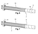
figures 6 à 13 illustrent en perspective le procédé de mise en place de cet agencement, conforme à l'invention. - Comme représenté sur les
figures 1 et 2 , une ligne d'un câble supraconducteur comporte une enceinte remplie d'un fluide cryogénique appelée cryostat 1 contenant le câble 2 dont les extrémités sont disposées dans une terminaison 3A, 3B où le support métallique résistif du câble est raccordé à des sorties 4A, 4B. - Le câble 2 comporte un écran externe constitué d'éléments métalliques, sous forme de fils ou de bandes, enroulés auquel est appliqué mécaniquement un effort de blocage sollicitant uniquement l'écran en un endroit dit de blocage 5A, 5B à proximité des extrémités du câble. Cet effort de blocage ne sollicite pas le corps de câble à l'endroit de blocage.
- La ligne peut également comprendre un module de cryostat additionnel 6A, 6B disposé entre le cryostat 1 et les terminaisons 3A, 3B.
- De façon générale, le procédé conforme à l'invention consiste à bloquer mécaniquement l'écran entre chacune des extrémités du câble 1 et le cryostat 1.
- Ces endroits de blocage peuvent être disposés dans les terminaisons 3A, 3B comme illustré sur la
figure 1 ou de préférence dans les modules de cryostat additionnel 6A, 6B comme illustré sur lafigure 2 . - L'effort de blocage est transmis à un dispositif de support 7A, 7B résistant mécaniquement et fixé au sol ou équivalent. En général, l'agencement de blocage est solidarisé à l'enceinte du cryostat 1 ou du module de cryostat additionnel 6A, 6B et cette enceinte est quant à elle solidement solidarisée au sol.
- La contraction entre l'endroit de blocage 5A, 5B et l'extrémité proche du câble peut quant à elle être gérée par un contact glissant.
- Les
figures 3 à 5 représentent en coupe verticale des modes de réalisation d'un agencement de blocage pour la mise en oeuvre d'un tel procédé. - Cet agencement de blocage comporte une bague 8 de surface externe lisse disposée sous l'écran 2A audit endroit de blocage et deux brides annulaires 9, 10 de diamètre interne légèrement supérieur au diamètre externe du câble 1 et de forme interne complémentaire disposées de part et d'autre du plan de symétrie de la bague et serrées l'une à l'autre, au moyen d'un ensemble de vissage. Cette bague présente un diamètre interne légèrement supérieur au diamètre externe du câble hors l'écran 2A.
- De préférence, la bague 8 a une surface externe bombée en forme d'arc de cercle et les brides annulaires 9, 10 ont une forme interne arrondie complémentaire.
- Cette bague 8 est en matériau résistant mécaniquement et n'a pas de propriété électrique spécifique. Elle est de préférence en acier inoxydable.
- Ces brides 9, 10 sont solidarisées à un dispositif de support 12 solidarisé au sol 7.
- L'ensemble de vissage 11 peut être unique et assurer la fixation des deux brides 9, 10 ensemble et également sur le dispositif de support 12, comme illustré sur la
figure 3 . - Deux ensembles de vissage peuvent également être prévus, l'une 11' assurant la fixation des deux brides 9, 10 ensemble, et l'autre 11" assurant la fixation d'une des brides 9 sur le dispositif de support 12, comme illustré sur la
figure 4 . - L'ensemble de vissage 11"' peut être unique et assurer la fixation des deux brides 9, 10 ensemble, l'une des brides 9 étant soudée sur le dispositif de support 12, comme illustré sur la
figure 5 . - Les
figures 6 à 13 illustrent en perspective le procédé de mise en place de cet agencement. - Comme illustré sur la
figure 6 , une des brides 10 est enfilé sur le câble 2 à son extrémité concernée et une partie de l'écran 2A est enlevée à cette extrémité et la bague 8 y est enfilée. Elle comporte un ensemble d'orifices 8A dont la fonction sera précisée plus loin. - Comme illustré sur la
figure 7 , la bague 8 est glissée partiellement sous l'écran 2A. - Comme illustré sur la
figure 8 , deux poignées externes amovibles 13A, 13B sont introduites dans deux orifices 8A diamétralement opposée. Ces poignées sont en forme de simples tirants. - Comme illustré sur les
figure 9 et 10 , les deux poignées externes amovibles 13A, 13B sont disposées entre deux éléments conducteurs adjacents de l'écran 2A et la bague 8 est glissée sous l'écran de l'extrémité du câble jusqu'à l'endroit de blocage par rotation et coulissement selon la flèche F en suivant le pas de ces deux éléments conducteurs, jusqu'à l'endroit de blocage. - Comme illustré sur la
figure 11 , les poignées 13A, 13B sont démontées et la seconde bride 9 est alors enfilée sur l'extrémité du câble. - Comme illustré sur la
figure 12 , les deux brides 9, 10 sont amenées en butée contre le renflement formé par la bague 8 sous l'écran 2A. - Comme illustré sur la
figure 13 , l'ensemble de vissage 11 constitué d'un certain nombre de boulons est disposé dans des orifices portés par les brides 9, 10 et vient serrer les deux brides contre la bague 8 avec l'écran 2A intercalé.
Claims (10)
- Procédé de gestion de la contraction thermique d'un câble supraconducteur (2) comportant un corps de câble entouré d'un écran externe (2A) constitué d'éléments métalliques enroulés et installé entre ses extrémités dans une enceinte (1) ou cryostat remplie d'un fluide cryogénique, caractérisé en ce qu'il consiste à appliquer mécaniquement un effort de blocage sollicitant uniquement ledit écran (2A) en un endroit dit de blocage (5A, 5B) à proximité desdites extrémités du câble.
- Procédé selon la revendication précédente, caractérisé en ce qu'il consiste à bloquer mécaniquement ledit écran (2A) entre chacune desdites extrémités du câble (2) et ladite enceinte (1).
- Procédé selon la revendication précédente, caractérisé en ce qu'il consiste à bloquer mécaniquement ledit écran (2A) dans un module de cryostat supplémentaire (6A, 6B) intercalé entre chacune desdites extrémités du câble (2) et ladite enceinte (1).
- Procédé selon l'une des revendications précédentes, caractérisé en ce que ledit effort de blocage est transmis à un dispositif de support (7A, 7B) fixé au sol ou équivalent.
- Procédé selon l'une des revendications précédentes, caractérisé en ce que la contraction entre ledit endroit de blocage (5A, 5B) et l'extrémité proche du câble (1) est gérée par un contact glissant.
- Agencement de blocage pour la mise en oeuvre du procédé selon l'une des revendications précédentes, caractérisé en ce qu'il comporte une bague (8) disposée sous ledit écran (2A) audit endroit de blocage (5A, 5B) et deux brides annulaires (9, 10) de forme interne complémentaire disposées de part et d'autre du plan de symétrie de ladite bague (8) et serrées l'une à l'autre
- Agencement selon la revendication précédente, caractérisé en ce que ladite bague (8) a une surface externe bombée en forme d'arc de cercle et lesdites brides annulaires (9, 10) ont une forme interne arrondie complémentaire.
- Agencement selon la 6 ou 7, caractérisé en ce que au moins l'une desdites brides (9, 10) est solidarisée à un dispositif de support (7A, 7B) fixé au sol ou équivalent.
- Procédé de mise en place d'un arrangement selon l'une des revendications 5 à 7, caractérisé en ce qu'il consiste à glisser ladite bague (8) sous ledit écran (2A) de l'extrémité du câble jusqu'à l'endroit de blocage (5A, 5B) puis de mettre en place lesdites brides (9, 10).
- Procédé selon la revendication précédente, caractérisé en ce qu'à l'extrémité du câble, ladite bague (8) est équipé de deux poignées externes amovibles (13A, 13B) disposées entre deux éléments conducteurs adjacents de l'écran (2A) et en ce qu'il est tourné et coulissé jusqu'à l'endroit de blocage (5A, 5B).
Applications Claiming Priority (1)
| Application Number | Priority Date | Filing Date | Title |
|---|---|---|---|
| FR1056878 | 2010-08-31 |
Publications (2)
| Publication Number | Publication Date |
|---|---|
| EP2424058A1 true EP2424058A1 (fr) | 2012-02-29 |
| EP2424058B1 EP2424058B1 (fr) | 2017-04-05 |
Family
ID=43855350
Family Applications (1)
| Application Number | Title | Priority Date | Filing Date |
|---|---|---|---|
| EP11177087.1A Active EP2424058B1 (fr) | 2010-08-31 | 2011-08-10 | Procede de gestion de la contraction thermique d'un cable supraconducteur et agencement pour la mise en oeuvre de ce procede |
Country Status (6)
| Country | Link |
|---|---|
| US (1) | US8583202B2 (fr) |
| EP (1) | EP2424058B1 (fr) |
| JP (1) | JP5916315B2 (fr) |
| KR (1) | KR101912842B1 (fr) |
| CN (1) | CN102385956B (fr) |
| RU (1) | RU2566297C2 (fr) |
Cited By (3)
| Publication number | Priority date | Publication date | Assignee | Title |
|---|---|---|---|---|
| CN105301461A (zh) * | 2015-11-27 | 2016-02-03 | 云南电网有限责任公司电力科学研究院 | 绕包超导体绝缘性能的测试装置及其测试方法 |
| US20210384126A1 (en) * | 2018-09-19 | 2021-12-09 | Psiquantum Corp | Tapered Connectors for Superconductor Circuits |
| WO2025196377A1 (fr) | 2024-03-20 | 2025-09-25 | Nexans | Procédé de formation d'une connexion électrique sur un câble supraconducteur |
Families Citing this family (3)
| Publication number | Priority date | Publication date | Assignee | Title |
|---|---|---|---|---|
| EP2426676A1 (fr) * | 2010-09-02 | 2012-03-07 | Nexans | Agencement doté d'au moins un câble supraconducteur |
| EP2961017A1 (fr) * | 2014-06-24 | 2015-12-30 | Nexans | Procédé et agencement de montage d'un système de câbles supraconducteurs |
| KR101557988B1 (ko) | 2014-09-11 | 2015-10-12 | 대한전선 주식회사 | 극저온 기중 종단접속함 |
Citations (4)
| Publication number | Priority date | Publication date | Assignee | Title |
|---|---|---|---|---|
| GB196511A (en) * | 1922-06-08 | 1923-04-26 | Johnson And Phillips Ltd | Improvements relating to means for gripping electric cables to junction boxes or thelike |
| EP0144146A2 (fr) * | 1983-11-01 | 1985-06-12 | John Sardinha Duarte | Jonction de câbles |
| EP1489692A2 (fr) | 2003-06-19 | 2004-12-22 | Sumitomo Electric Industries, Ltd. | Dispositif de connexion de câble cryogénique |
| WO2008113366A2 (fr) * | 2007-03-21 | 2008-09-25 | Nkt Cables Ultera A/S | Unité de terminaison |
Family Cites Families (6)
| Publication number | Priority date | Publication date | Assignee | Title |
|---|---|---|---|---|
| CA2399462C (fr) * | 2000-02-09 | 2008-07-29 | Nkt Cables Gmbh | Boite d'extremite de cable |
| CA2505501A1 (fr) * | 2004-05-04 | 2005-11-04 | Nexans | Methode de stabilisation mecanique de ceramiques supraconductrices en forme de tube et composite supraconducteur en forme de tube stabilise mecaniquement |
| JP2006014547A (ja) * | 2004-06-29 | 2006-01-12 | Tokyo Electric Power Co Inc:The | 超電導ケーブル接続装置 |
| CN1311918C (zh) * | 2004-07-23 | 2007-04-25 | 聚光科技(杭州)有限公司 | 在位式光电分析系统测量通道的除污方法及其装置 |
| JP4826797B2 (ja) * | 2007-02-23 | 2011-11-30 | 住友電気工業株式会社 | 超電導ケーブル線路の設計方法及び超電導ケーブル線路 |
| FR2930378B1 (fr) * | 2008-04-16 | 2010-05-14 | Nexans | Agencement de connexion de deux cables supraconducteurs |
-
2011
- 2011-08-08 US US13/204,897 patent/US8583202B2/en active Active
- 2011-08-10 EP EP11177087.1A patent/EP2424058B1/fr active Active
- 2011-08-16 JP JP2011177963A patent/JP5916315B2/ja active Active
- 2011-08-25 CN CN201110245105.XA patent/CN102385956B/zh not_active Expired - Fee Related
- 2011-08-30 RU RU2011136138/07A patent/RU2566297C2/ru active
- 2011-08-30 KR KR1020110087224A patent/KR101912842B1/ko not_active Expired - Fee Related
Patent Citations (4)
| Publication number | Priority date | Publication date | Assignee | Title |
|---|---|---|---|---|
| GB196511A (en) * | 1922-06-08 | 1923-04-26 | Johnson And Phillips Ltd | Improvements relating to means for gripping electric cables to junction boxes or thelike |
| EP0144146A2 (fr) * | 1983-11-01 | 1985-06-12 | John Sardinha Duarte | Jonction de câbles |
| EP1489692A2 (fr) | 2003-06-19 | 2004-12-22 | Sumitomo Electric Industries, Ltd. | Dispositif de connexion de câble cryogénique |
| WO2008113366A2 (fr) * | 2007-03-21 | 2008-09-25 | Nkt Cables Ultera A/S | Unité de terminaison |
Cited By (5)
| Publication number | Priority date | Publication date | Assignee | Title |
|---|---|---|---|---|
| CN105301461A (zh) * | 2015-11-27 | 2016-02-03 | 云南电网有限责任公司电力科学研究院 | 绕包超导体绝缘性能的测试装置及其测试方法 |
| US20210384126A1 (en) * | 2018-09-19 | 2021-12-09 | Psiquantum Corp | Tapered Connectors for Superconductor Circuits |
| US11830811B2 (en) * | 2018-09-19 | 2023-11-28 | PsiQuantum Corp. | Tapered connectors for superconductor circuits |
| US12199039B2 (en) | 2018-09-19 | 2025-01-14 | PsiQuantum Corp. | Tapered connectors for superconductor circuits |
| WO2025196377A1 (fr) | 2024-03-20 | 2025-09-25 | Nexans | Procédé de formation d'une connexion électrique sur un câble supraconducteur |
Also Published As
| Publication number | Publication date |
|---|---|
| JP5916315B2 (ja) | 2016-05-11 |
| KR20120042644A (ko) | 2012-05-03 |
| JP2012070617A (ja) | 2012-04-05 |
| RU2011136138A (ru) | 2013-03-10 |
| EP2424058B1 (fr) | 2017-04-05 |
| CN102385956A (zh) | 2012-03-21 |
| CN102385956B (zh) | 2015-11-25 |
| RU2566297C2 (ru) | 2015-10-20 |
| US20120053061A1 (en) | 2012-03-01 |
| US8583202B2 (en) | 2013-11-12 |
| KR101912842B1 (ko) | 2018-10-30 |
Similar Documents
| Publication | Publication Date | Title |
|---|---|---|
| EP2424058B1 (fr) | Procede de gestion de la contraction thermique d'un cable supraconducteur et agencement pour la mise en oeuvre de ce procede | |
| EP1928001B1 (fr) | Conducteur de transport électrique pour une ligne aérienne | |
| EP2146395B1 (fr) | Manchon de connexion d'un câble supraconducteur et terminaison de connexion au moyen de ce manchon | |
| EP2104197A1 (fr) | Structure de connexion électrique pour élement supraconducteur | |
| EP2110887B1 (fr) | Agencement de connexion de deux câbles supraconducteurs | |
| CN112041160B (zh) | 高架电缆的端接装置 | |
| FR2929454A1 (fr) | Dispositif de connexion de deux cables supraconducteurs | |
| EP2852001B1 (fr) | Jonction de câbles supraconducteurs | |
| EP0660478A1 (fr) | Ligne à haute tension à isolation gazeuse pour longue distance | |
| EP1703611A1 (fr) | Traversée électrique pour élement supraconducteur | |
| FR2844101A1 (fr) | Connecteur de deux cables d'energie electrique et connexion comportant un tel connecteur | |
| FR2460056A1 (fr) | Procede de fixation d'une piece de contact sur une ligne electrique | |
| EP2038978B1 (fr) | Structure de traversee electrique pour element supraconducteur | |
| WO2014176706A1 (fr) | Procede de fabrication d'un cable chauffant et cable chauffant realise selon ce procede | |
| EP0669677B1 (fr) | Dispositif de connexion électrique pour écrans de câbles conducteurs, et procédé pour sa mise en oeuvre | |
| FR3001574A1 (fr) | Cable d'energie et/ou de telecommunication comportant au moins une couche electriquement isolante | |
| FR2958807A1 (fr) | Dispositif de connexion de deux cables supraconducteurs | |
| EP3886276A1 (fr) | Dispositif support sous forme de potence pour cable electrique haute tension | |
| FR2585192A1 (fr) | Connecteur electrique destine a realiser une derivation electrique a partir d'un cable electrique forme d'un conducteur entoure d'une gaine isolante | |
| FR2748845A1 (fr) | Cable electrique de transmission haute frequence | |
| WO2025196377A1 (fr) | Procédé de formation d'une connexion électrique sur un câble supraconducteur | |
| FR2555372A1 (fr) | Jonction souple de raccordement de deux cables d'energie a haute tension | |
| FR3017986A1 (fr) | Blindage electromagnetique tresse pour cables | |
| FR3061556A1 (fr) | Procede de controle d'une conduite sous-marine et dispositif pour sa mise en œuvre | |
| EP4387023A1 (fr) | Procédé et ensemble de traitement d'un manchon d'ancrage de câble conducteur, manchon d'ancrage résultant |
Legal Events
| Date | Code | Title | Description |
|---|---|---|---|
| AK | Designated contracting states |
Kind code of ref document: A1 Designated state(s): AL AT BE BG CH CY CZ DE DK EE ES FI FR GB GR HR HU IE IS IT LI LT LU LV MC MK MT NL NO PL PT RO RS SE SI SK SM TR |
|
| AX | Request for extension of the european patent |
Extension state: BA ME |
|
| PUAI | Public reference made under article 153(3) epc to a published international application that has entered the european phase |
Free format text: ORIGINAL CODE: 0009012 |
|
| 17P | Request for examination filed |
Effective date: 20120829 |
|
| 17Q | First examination report despatched |
Effective date: 20151016 |
|
| GRAJ | Information related to disapproval of communication of intention to grant by the applicant or resumption of examination proceedings by the epo deleted |
Free format text: ORIGINAL CODE: EPIDOSDIGR1 |
|
| GRAP | Despatch of communication of intention to grant a patent |
Free format text: ORIGINAL CODE: EPIDOSNIGR1 |
|
| INTG | Intention to grant announced |
Effective date: 20161110 |
|
| RIN1 | Information on inventor provided before grant (corrected) |
Inventor name: LALLOUET, NICOLAS Inventor name: SCHMIDT, FRANK Inventor name: DELPLACE, SEBASTIEN Inventor name: MARZAHN, ERIK |
|
| GRAS | Grant fee paid |
Free format text: ORIGINAL CODE: EPIDOSNIGR3 |
|
| GRAA | (expected) grant |
Free format text: ORIGINAL CODE: 0009210 |
|
| AK | Designated contracting states |
Kind code of ref document: B1 Designated state(s): AL AT BE BG CH CY CZ DE DK EE ES FI FR GB GR HR HU IE IS IT LI LT LU LV MC MK MT NL NO PL PT RO RS SE SI SK SM TR |
|
| REG | Reference to a national code |
Ref country code: GB Ref legal event code: FG4D Free format text: NOT ENGLISH |
|
| REG | Reference to a national code |
Ref country code: CH Ref legal event code: EP |
|
| REG | Reference to a national code |
Ref country code: AT Ref legal event code: REF Ref document number: 882645 Country of ref document: AT Kind code of ref document: T Effective date: 20170415 |
|
| REG | Reference to a national code |
Ref country code: IE Ref legal event code: FG4D Free format text: LANGUAGE OF EP DOCUMENT: FRENCH |
|
| REG | Reference to a national code |
Ref country code: DE Ref legal event code: R096 Ref document number: 602011036601 Country of ref document: DE |
|
| REG | Reference to a national code |
Ref country code: NL Ref legal event code: FP |
|
| RAP2 | Party data changed (patent owner data changed or rights of a patent transferred) |
Owner name: NEXANS |
|
| REG | Reference to a national code |
Ref country code: FR Ref legal event code: PLFP Year of fee payment: 7 |
|
| REG | Reference to a national code |
Ref country code: LT Ref legal event code: MG4D |
|
| REG | Reference to a national code |
Ref country code: AT Ref legal event code: MK05 Ref document number: 882645 Country of ref document: AT Kind code of ref document: T Effective date: 20170405 |
|
| PG25 | Lapsed in a contracting state [announced via postgrant information from national office to epo] |
Ref country code: AT Free format text: LAPSE BECAUSE OF FAILURE TO SUBMIT A TRANSLATION OF THE DESCRIPTION OR TO PAY THE FEE WITHIN THE PRESCRIBED TIME-LIMIT Effective date: 20170405 Ref country code: LT Free format text: LAPSE BECAUSE OF FAILURE TO SUBMIT A TRANSLATION OF THE DESCRIPTION OR TO PAY THE FEE WITHIN THE PRESCRIBED TIME-LIMIT Effective date: 20170405 Ref country code: FI Free format text: LAPSE BECAUSE OF FAILURE TO SUBMIT A TRANSLATION OF THE DESCRIPTION OR TO PAY THE FEE WITHIN THE PRESCRIBED TIME-LIMIT Effective date: 20170405 Ref country code: HR Free format text: LAPSE BECAUSE OF FAILURE TO SUBMIT A TRANSLATION OF THE DESCRIPTION OR TO PAY THE FEE WITHIN THE PRESCRIBED TIME-LIMIT Effective date: 20170405 Ref country code: GR Free format text: LAPSE BECAUSE OF FAILURE TO SUBMIT A TRANSLATION OF THE DESCRIPTION OR TO PAY THE FEE WITHIN THE PRESCRIBED TIME-LIMIT Effective date: 20170706 Ref country code: NO Free format text: LAPSE BECAUSE OF FAILURE TO SUBMIT A TRANSLATION OF THE DESCRIPTION OR TO PAY THE FEE WITHIN THE PRESCRIBED TIME-LIMIT Effective date: 20170705 Ref country code: ES Free format text: LAPSE BECAUSE OF FAILURE TO SUBMIT A TRANSLATION OF THE DESCRIPTION OR TO PAY THE FEE WITHIN THE PRESCRIBED TIME-LIMIT Effective date: 20170405 |
|
| PG25 | Lapsed in a contracting state [announced via postgrant information from national office to epo] |
Ref country code: LV Free format text: LAPSE BECAUSE OF FAILURE TO SUBMIT A TRANSLATION OF THE DESCRIPTION OR TO PAY THE FEE WITHIN THE PRESCRIBED TIME-LIMIT Effective date: 20170405 Ref country code: PL Free format text: LAPSE BECAUSE OF FAILURE TO SUBMIT A TRANSLATION OF THE DESCRIPTION OR TO PAY THE FEE WITHIN THE PRESCRIBED TIME-LIMIT Effective date: 20170405 Ref country code: BG Free format text: LAPSE BECAUSE OF FAILURE TO SUBMIT A TRANSLATION OF THE DESCRIPTION OR TO PAY THE FEE WITHIN THE PRESCRIBED TIME-LIMIT Effective date: 20170705 Ref country code: IS Free format text: LAPSE BECAUSE OF FAILURE TO SUBMIT A TRANSLATION OF THE DESCRIPTION OR TO PAY THE FEE WITHIN THE PRESCRIBED TIME-LIMIT Effective date: 20170805 Ref country code: SE Free format text: LAPSE BECAUSE OF FAILURE TO SUBMIT A TRANSLATION OF THE DESCRIPTION OR TO PAY THE FEE WITHIN THE PRESCRIBED TIME-LIMIT Effective date: 20170405 Ref country code: RS Free format text: LAPSE BECAUSE OF FAILURE TO SUBMIT A TRANSLATION OF THE DESCRIPTION OR TO PAY THE FEE WITHIN THE PRESCRIBED TIME-LIMIT Effective date: 20170405 |
|
| REG | Reference to a national code |
Ref country code: DE Ref legal event code: R097 Ref document number: 602011036601 Country of ref document: DE |
|
| PG25 | Lapsed in a contracting state [announced via postgrant information from national office to epo] |
Ref country code: EE Free format text: LAPSE BECAUSE OF FAILURE TO SUBMIT A TRANSLATION OF THE DESCRIPTION OR TO PAY THE FEE WITHIN THE PRESCRIBED TIME-LIMIT Effective date: 20170405 Ref country code: CZ Free format text: LAPSE BECAUSE OF FAILURE TO SUBMIT A TRANSLATION OF THE DESCRIPTION OR TO PAY THE FEE WITHIN THE PRESCRIBED TIME-LIMIT Effective date: 20170405 Ref country code: SK Free format text: LAPSE BECAUSE OF FAILURE TO SUBMIT A TRANSLATION OF THE DESCRIPTION OR TO PAY THE FEE WITHIN THE PRESCRIBED TIME-LIMIT Effective date: 20170405 Ref country code: DK Free format text: LAPSE BECAUSE OF FAILURE TO SUBMIT A TRANSLATION OF THE DESCRIPTION OR TO PAY THE FEE WITHIN THE PRESCRIBED TIME-LIMIT Effective date: 20170405 Ref country code: RO Free format text: LAPSE BECAUSE OF FAILURE TO SUBMIT A TRANSLATION OF THE DESCRIPTION OR TO PAY THE FEE WITHIN THE PRESCRIBED TIME-LIMIT Effective date: 20170405 |
|
| PLBE | No opposition filed within time limit |
Free format text: ORIGINAL CODE: 0009261 |
|
| STAA | Information on the status of an ep patent application or granted ep patent |
Free format text: STATUS: NO OPPOSITION FILED WITHIN TIME LIMIT |
|
| PG25 | Lapsed in a contracting state [announced via postgrant information from national office to epo] |
Ref country code: IT Free format text: LAPSE BECAUSE OF FAILURE TO SUBMIT A TRANSLATION OF THE DESCRIPTION OR TO PAY THE FEE WITHIN THE PRESCRIBED TIME-LIMIT Effective date: 20170405 Ref country code: SM Free format text: LAPSE BECAUSE OF FAILURE TO SUBMIT A TRANSLATION OF THE DESCRIPTION OR TO PAY THE FEE WITHIN THE PRESCRIBED TIME-LIMIT Effective date: 20170405 |
|
| 26N | No opposition filed |
Effective date: 20180108 |
|
| REG | Reference to a national code |
Ref country code: CH Ref legal event code: PL |
|
| PG25 | Lapsed in a contracting state [announced via postgrant information from national office to epo] |
Ref country code: MC Free format text: LAPSE BECAUSE OF FAILURE TO SUBMIT A TRANSLATION OF THE DESCRIPTION OR TO PAY THE FEE WITHIN THE PRESCRIBED TIME-LIMIT Effective date: 20170405 |
|
| GBPC | Gb: european patent ceased through non-payment of renewal fee |
Effective date: 20170810 |
|
| PG25 | Lapsed in a contracting state [announced via postgrant information from national office to epo] |
Ref country code: LI Free format text: LAPSE BECAUSE OF NON-PAYMENT OF DUE FEES Effective date: 20170831 Ref country code: CH Free format text: LAPSE BECAUSE OF NON-PAYMENT OF DUE FEES Effective date: 20170831 |
|
| REG | Reference to a national code |
Ref country code: IE Ref legal event code: MM4A |
|
| PG25 | Lapsed in a contracting state [announced via postgrant information from national office to epo] |
Ref country code: SI Free format text: LAPSE BECAUSE OF FAILURE TO SUBMIT A TRANSLATION OF THE DESCRIPTION OR TO PAY THE FEE WITHIN THE PRESCRIBED TIME-LIMIT Effective date: 20170405 |
|
| REG | Reference to a national code |
Ref country code: BE Ref legal event code: MM Effective date: 20170831 |
|
| PG25 | Lapsed in a contracting state [announced via postgrant information from national office to epo] |
Ref country code: LU Free format text: LAPSE BECAUSE OF NON-PAYMENT OF DUE FEES Effective date: 20170810 |
|
| PG25 | Lapsed in a contracting state [announced via postgrant information from national office to epo] |
Ref country code: GB Free format text: LAPSE BECAUSE OF NON-PAYMENT OF DUE FEES Effective date: 20170810 Ref country code: IE Free format text: LAPSE BECAUSE OF NON-PAYMENT OF DUE FEES Effective date: 20170810 |
|
| REG | Reference to a national code |
Ref country code: FR Ref legal event code: PLFP Year of fee payment: 8 |
|
| PG25 | Lapsed in a contracting state [announced via postgrant information from national office to epo] |
Ref country code: BE Free format text: LAPSE BECAUSE OF NON-PAYMENT OF DUE FEES Effective date: 20170831 |
|
| PG25 | Lapsed in a contracting state [announced via postgrant information from national office to epo] |
Ref country code: MT Free format text: LAPSE BECAUSE OF FAILURE TO SUBMIT A TRANSLATION OF THE DESCRIPTION OR TO PAY THE FEE WITHIN THE PRESCRIBED TIME-LIMIT Effective date: 20170405 |
|
| PG25 | Lapsed in a contracting state [announced via postgrant information from national office to epo] |
Ref country code: HU Free format text: LAPSE BECAUSE OF FAILURE TO SUBMIT A TRANSLATION OF THE DESCRIPTION OR TO PAY THE FEE WITHIN THE PRESCRIBED TIME-LIMIT; INVALID AB INITIO Effective date: 20110810 |
|
| PG25 | Lapsed in a contracting state [announced via postgrant information from national office to epo] |
Ref country code: CY Free format text: LAPSE BECAUSE OF NON-PAYMENT OF DUE FEES Effective date: 20170405 |
|
| PG25 | Lapsed in a contracting state [announced via postgrant information from national office to epo] |
Ref country code: MK Free format text: LAPSE BECAUSE OF FAILURE TO SUBMIT A TRANSLATION OF THE DESCRIPTION OR TO PAY THE FEE WITHIN THE PRESCRIBED TIME-LIMIT Effective date: 20170405 |
|
| PG25 | Lapsed in a contracting state [announced via postgrant information from national office to epo] |
Ref country code: TR Free format text: LAPSE BECAUSE OF FAILURE TO SUBMIT A TRANSLATION OF THE DESCRIPTION OR TO PAY THE FEE WITHIN THE PRESCRIBED TIME-LIMIT Effective date: 20170405 |
|
| PG25 | Lapsed in a contracting state [announced via postgrant information from national office to epo] |
Ref country code: PT Free format text: LAPSE BECAUSE OF FAILURE TO SUBMIT A TRANSLATION OF THE DESCRIPTION OR TO PAY THE FEE WITHIN THE PRESCRIBED TIME-LIMIT Effective date: 20170405 |
|
| PG25 | Lapsed in a contracting state [announced via postgrant information from national office to epo] |
Ref country code: AL Free format text: LAPSE BECAUSE OF FAILURE TO SUBMIT A TRANSLATION OF THE DESCRIPTION OR TO PAY THE FEE WITHIN THE PRESCRIBED TIME-LIMIT Effective date: 20170405 |
|
| PGFP | Annual fee paid to national office [announced via postgrant information from national office to epo] |
Ref country code: NL Payment date: 20250821 Year of fee payment: 15 |
|
| PGFP | Annual fee paid to national office [announced via postgrant information from national office to epo] |
Ref country code: DE Payment date: 20250820 Year of fee payment: 15 |
|
| PGFP | Annual fee paid to national office [announced via postgrant information from national office to epo] |
Ref country code: FR Payment date: 20250829 Year of fee payment: 15 |