EP2423934A2 - Tactile switch and method for manufacturing tactile switch - Google Patents
Tactile switch and method for manufacturing tactile switch Download PDFInfo
- Publication number
- EP2423934A2 EP2423934A2 EP11179233A EP11179233A EP2423934A2 EP 2423934 A2 EP2423934 A2 EP 2423934A2 EP 11179233 A EP11179233 A EP 11179233A EP 11179233 A EP11179233 A EP 11179233A EP 2423934 A2 EP2423934 A2 EP 2423934A2
- Authority
- EP
- European Patent Office
- Prior art keywords
- cover sheet
- face
- end part
- tactile switch
- angle
- Prior art date
- Legal status (The legal status is an assumption and is not a legal conclusion. Google has not performed a legal analysis and makes no representation as to the accuracy of the status listed.)
- Granted
Links
- 238000000034 method Methods 0.000 title claims description 24
- 238000004519 manufacturing process Methods 0.000 title claims description 17
- 239000011347 resin Substances 0.000 claims description 72
- 229920005989 resin Polymers 0.000 claims description 72
- 238000007788 roughening Methods 0.000 claims description 5
- 230000003746 surface roughness Effects 0.000 claims description 5
- 238000007599 discharging Methods 0.000 claims description 2
- 239000000463 material Substances 0.000 description 27
- 238000003825 pressing Methods 0.000 description 18
- 230000002093 peripheral effect Effects 0.000 description 13
- 230000000052 comparative effect Effects 0.000 description 10
- 229920001721 polyimide Polymers 0.000 description 5
- 230000005489 elastic deformation Effects 0.000 description 4
- 239000012790 adhesive layer Substances 0.000 description 3
- 239000009719 polyimide resin Substances 0.000 description 3
- 239000004696 Poly ether ether ketone Substances 0.000 description 2
- 239000004642 Polyimide Substances 0.000 description 2
- 239000004734 Polyphenylene sulfide Substances 0.000 description 2
- 239000012141 concentrate Substances 0.000 description 2
- 238000010586 diagram Methods 0.000 description 2
- 229920002530 polyetherether ketone Polymers 0.000 description 2
- 229920000069 polyphenylene sulfide Polymers 0.000 description 2
- 238000005488 sandblasting Methods 0.000 description 2
- 239000004925 Acrylic resin Substances 0.000 description 1
- 229920000178 Acrylic resin Polymers 0.000 description 1
- 229920000106 Liquid crystal polymer Polymers 0.000 description 1
- 239000004977 Liquid-crystal polymers (LCPs) Substances 0.000 description 1
- 239000004677 Nylon Substances 0.000 description 1
- 244000137852 Petrea volubilis Species 0.000 description 1
- 230000001413 cellular effect Effects 0.000 description 1
- 238000005260 corrosion Methods 0.000 description 1
- 230000007797 corrosion Effects 0.000 description 1
- 239000000428 dust Substances 0.000 description 1
- 239000007788 liquid Substances 0.000 description 1
- 239000011344 liquid material Substances 0.000 description 1
- 239000002184 metal Substances 0.000 description 1
- 229920001778 nylon Polymers 0.000 description 1
- 238000005498 polishing Methods 0.000 description 1
- 229910000679 solder Inorganic materials 0.000 description 1
- 229920001187 thermosetting polymer Polymers 0.000 description 1
- XLYOFNOQVPJJNP-UHFFFAOYSA-N water Substances O XLYOFNOQVPJJNP-UHFFFAOYSA-N 0.000 description 1
Images



Classifications
-
- H—ELECTRICITY
- H01—ELECTRIC ELEMENTS
- H01H—ELECTRIC SWITCHES; RELAYS; SELECTORS; EMERGENCY PROTECTIVE DEVICES
- H01H13/00—Switches having rectilinearly-movable operating part or parts adapted for pushing or pulling in one direction only, e.g. push-button switch
- H01H13/02—Details
- H01H13/26—Snap-action arrangements depending upon deformation of elastic members
- H01H13/48—Snap-action arrangements depending upon deformation of elastic members using buckling of disc springs
-
- H—ELECTRICITY
- H01—ELECTRIC ELEMENTS
- H01H—ELECTRIC SWITCHES; RELAYS; SELECTORS; EMERGENCY PROTECTIVE DEVICES
- H01H13/00—Switches having rectilinearly-movable operating part or parts adapted for pushing or pulling in one direction only, e.g. push-button switch
- H01H13/02—Details
- H01H13/12—Movable parts; Contacts mounted thereon
- H01H13/14—Operating parts, e.g. push-button
-
- Y—GENERAL TAGGING OF NEW TECHNOLOGICAL DEVELOPMENTS; GENERAL TAGGING OF CROSS-SECTIONAL TECHNOLOGIES SPANNING OVER SEVERAL SECTIONS OF THE IPC; TECHNICAL SUBJECTS COVERED BY FORMER USPC CROSS-REFERENCE ART COLLECTIONS [XRACs] AND DIGESTS
- Y10—TECHNICAL SUBJECTS COVERED BY FORMER USPC
- Y10T—TECHNICAL SUBJECTS COVERED BY FORMER US CLASSIFICATION
- Y10T29/00—Metal working
- Y10T29/49—Method of mechanical manufacture
- Y10T29/49002—Electrical device making
- Y10T29/49105—Switch making
Definitions
- the present invention is related to a tactile switch used in various kinds of electronic devices and a method for manufacturing the tactile switch.
- a tactile switch is known as a signal input device used in a compact and thin electronic device such as a cellular phone.
- the tactile switch since the thickness can be reduced, a good sense of operation can be obtained during an operation and an electrically stable contact can be obtained, the tactile switch is frequently used in the compact and thin electronic device.
- the positioning protrusion 205a of the push switch 201 disclosed in the patent literature 1 is formed so as to rise substantially at orthogonal to the flexible sheet 205. Accordingly, when the push switch 201 is pressed and operated to elastically deform the dome shaped movable contact 204, a stress is concentrated on a corner part 205b in which the positioning protrusion 205a rises from the flexible sheet 205 to generate a large distortion in the corner part 205b. Thus, when pressing operations are repeated many times, cracks are generated in the corner part 205b, and the cracks shortly expand, so that there is a fear that the operating force concentrating member 206 may possibly slip out from the flexible sheet 205 to shorten the life of the push switch 201.
- Patent Literature 1 Japanese Patent Publication No. 2009-140711 A
- a tactile switch comprising:
- the end part, the root part and the bent part may be integrally formed.
- a radius of curvature of the bent part may be equal to or larger than 0.025 mm and equal to or smaller than 0.035 mm.
- the first angle may equal to or larger than 15 degrees and equal to or smaller than 25 degrees.
- a surface roughness of the face of the cover sheet may be equal to or more than 0.30 ⁇ m and equal to or less than 0.36 ⁇ m.
- a method for manufacturing a tactile switch including:
- a roughening process may be applied to the face of the cover sheet so that a surface roughness is equal to or more than 0.30 ⁇ m and equal to or less than 0.36 ⁇ m.
- the plate After the plate is provided on the upper face of the resin portion, the plate may be lifted to lift the resin.
- Fig.1 is an exploded perspective view of a tactile switch 1 according to the present embodiment.
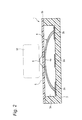
- the tactile switch 1 includes a base part 3 having an accommodating recessed part 3a opened to an upper part, a central fixed electrode 2a and peripheral fixed electrodes 2b (fixed contacts) fixed to a bottom surface of the accommodating recessed part 3a, a dome shaped click spring (an elastic conductive member) 4 accommodated in the accommodating recessed part 3a and arranged so as to protrude toward an opened surface side of the accommodating recessed part 3a and a cover sheet 5 that protects an upper surface 3b of the base part 3 and an upper part of the click spring 4.
- the base part 3 is a resin member of a substantially rectangular parallelepiped.
- the accommodating recessed part 3a opened to the upper part is formed.
- the central fixed electrode 2a is provided and the peripheral fixed electrodes 2b are provided in peripheral areas spaced from the central fixed electrode 2a.
- the click spring 4 made of metal is a member having a form of a dome protruding to an upper part and which can be elastically deformed. Further, at least a part of an end part of the click spring 4 comes into contact with the peripheral fixed electrodes 2b and is arranged in the recessed part 3a.
- the cover sheet 5 is a flexible insulating film provided on an upper part of the click spring 4.
- the cover sheer 5 is also elastically deformed so as to protrude downward in accordance with the deformation of the click spring 4.
- the cover sheet 5 covers the base part 3 and the click spring 4 to prevent dust or water from entering the accommodating recessed part 3a of the base part 3 from an external part and prevent the corrosion of the click spring 4 or the central fixed electrode 2a and the peripheral fixed electrodes 2b.
- the cover sheet 5 may be made of a resin such as polyimide. A back surface of the cover sheet 5 is bonded to the upper surface 3b of the base part 3 through an adhesive layer.
- An operating protrusion 6 is formed at a position of a substantially central part of a surface of the cover sheet 5 and corresponding to the central fixed electrode 2a.
- the operating protrusion 6 is provided so as to protrude to an opposite side to the click spring 4 from the surface of the cover sheet 5.
- the operating protrusion 6 is a member including an end part 6a whose end is a flat surface, a root part 6b fixed to the cover sheet 5 and having a diameter larger than that of the end part 6a and a bent part 6c that connects the end part 6a to the root part 6b.
- the end part 6a, the root part 6b and the bent part 6c are integrally formed.
- the operating protrusion 6 is formed in the shape whose diameter is gradually enlarged from the end part 6a to the root part 6b.
- a pressing member 10 having a large pressing area such as a button presses the top part 4a of the click spring 4 through the end part 6a of the operating protrusion 6 having a small area.
- a pressing force by the pressing member 10 is concentrated on the top part so that a large stress may be applied to the top part 4a of the click spring 4. Accordingly, even when relative positions of the pressing member 10 and the tactile switch 1 are slightly shifted, a pressing operation can be assuredly realized.
- a basic angle A1 of the root part 6b of the operating protrusion 6 is set to be smaller than an end angle A2 of the end part 6a.
- the basic angle A1 of the root part 6b is small, since the area of the root part 6b having the small thickness can be widely ensured in the diametrical direction and the large area is elastically deformed so that the concentration of stress may be suppressed, the occurrence or expansion of the cracks can be suppressed in the root part 6b. Since the concentration of stress does not occur in the end part 6a, a side wall of the end part 6a may have a sharp form (a form having a large end angle A2).
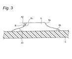
- the basic angle A1 mentioned herein is, as shown in Fig. 3 , an angle formed by the side wall of the root part 6b relative to the surface of the cover sheet 5.
- the end angle A2 is a supplementary angle of an angle formed by the side wall of the end part 6a relative to the surface of the cover sheet 5.
- the root part 6b is connected to the end part 6a by the bent part 6c and the basic angle A1 is made to be different from the end angle A2.
- a supplementary angle of an angle formed by a main part of the end part 6a relative to the surface of the cover sheet 5 is defined as the end angle A2 and an angle formed by a main part of the root part 6b relative to the surface of the cover sheet 5 is defined as the basic angle A1.
- a truncated cone shaped operating protrusion including a root part and an end part with a basic angle A1 equal to an end angle A2 that are formed in a straight line, which is different from the present embodiment
- the basic angle A1 when the basic angle A1 is tried to decrease, the operating protrusion becomes too large in a diametrical direction. Thus, an original purpose that the pressing force is to be concentrated cannot be achieved. Further, when the basic angle A1 is increased, the operating protrusion is liable to be separated from the cover sheet.
- the basic angle A1 of the operating protrusion in the present embodiment is preferably set to an angle of 15° or more and smaller than 25°.
- the thickness of the root part 6b is too small, so that the cracks are apt to occur due to an excessively small thickness.
- the thickness of the root part 6b is large, so that the root part 6b is hardly elastically deformed and the cracks are apt to occur.
- a boundary of the end part 6a and the root part 6b is preferably connected by the bent part 6c having a smooth curved surface with a radius of curvature of 0.025 mm or larger and 0.035 mm or smaller.
- the bent part 6c is formed in the boundary of the root part 6b and the end part 6a.
- the basic angle A1 of the root part 6b is set to be smaller than the end angle A2 of the end part 6a.
- the cover sheet 5 is elastically deformed together with the click spring 4
- the basic angle A1 of the operating protrusion 6 is small, the stress is hardly concentrated on the root part 6b of the operating protrusion 6. Accordingly, the cracks hardly occur in the root part 6b of the operating protrusion 6 and the operating protrusion 6 is hardly peeled off. Therefore, the tactile switch 1 having a long life can be provided.
- the operating protrusion 6 is provided in the opposite side to the click spring 4, however, the operating protrusion 6 may be provided in the same side as the click spring 4. Also in this case, since the pressing force can be concentrated on the top part 4a of the click spring 4, a good sense of operation can be obtained.
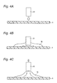
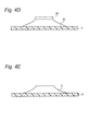
- FIGs. 4A to 4E are diagrams especially showing manufacturing processes of the operating protrusion 6.
- the operating protrusion 6 is provided on a polyimide tape forming the cover sheet 5.
- a discharge port of a nozzle 20 is allowed to come close to the surface of the cover sheet 5.
- the nozzle 20 serves to supply a liquid material resin such as an ultraviolet setting resin as a material of the operating protrusion 6 to the surface of the cover sheet 5 from a supply source not shown in the drawing.
- the material resin is discharged from the nozzle 20 to form a resin portion 30 on the surface of the cover sheet 5. Since the material resin discharged from the discharge port of the nozzle 20 is blocked on the surface of the cover sheet 5 to spread in the radial direction on the surface of the cover sheet 5, the material resin can be efficiently spread on a wide area.
- an amount of the discharged material resin is the same, as a contact surface of the resin portion 30 to the cover sheet 5 is more increased, an area of the operating protrusion 6 having the small thickness is more increased. Thus, preferably, the operating protrusion 6 is easily elastically deformed.
- a discharge pressure or a flow rate of the material resin and a space between the discharge port of the nozzle 20 and the surface of the cover sheet 5 are adjusted, a size of the bottom surface of the resin portion 30 can be adjusted.
- an angle formed by a terminal end (both ends of side parts in Fig. 4B ) of a part forming the root part 6b of the operating protrusion 6 relative to the surface of the cover sheet 5 may be occasionally large.
- the material resin is lifted upward by the lifting operation of the nozzle 20 as described above, since the peripheral area of the resin portion 30 is moved to the central area, the thickness of a terminal end area of the root part 6b of the operating protrusion 6 can be reduced.
- the operating protrusion 6 can be formed which is more hardly peeled off.
- a pressing plate 40 having a flat bottom surface is overlaid on the resin portion 30 from an upper part and held for a prescribed time to heat or irradiate the material resin with ultraviolet rays and harden the material resin.
- Fig. 4E when the material resin is hardened, and then, the pressing plate 40 is removed, the operating protrusion 6 can be formed on the surface of the cover sheet 5.
- the operating protrusion 6 can be preferably formed in which the basic angle A1 is small.
- the cover sheet 5 having the operating protrusion 6 obtained in such a way is overlaid and bonded onto the upper surface of the base part 3 having the accommodating recessed part 3a in which the central fixed electrode 2a, the peripheral fixed electrodes 2b and the click spring 4 are accommodated.
- the tactile switch 1 of the above-described embodiment can be obtained.
- thermosetting resin As the material resin of the operating protrusion 6, a thermosetting resin, an ultraviolet setting resin, a polyimide resin or the like may be used.
- a material of the cover sheet 5 an acrylic resin or a polyphenylene sulfide (PPS) resin, a liquid crystal polymer, a nylon resin and an a polyether ether ketone (PEEK) resin may be exemplified as well as the polyimide resin.
- PPS polyphenylene sulfide
- PEEK polyether ether ketone
- the bent part 6c that continuously and smoothly connects the end part 6a to the root part 6b can be formed.
- the bent part 6c can be formed which has a smooth curve with the radius of curvature R of 0.025 mm or larger and 0.035 mm or smaller. Accordingly, the occurrence and expansion of the cracks can be suppressed in the bent part 6c.
- the surface of the cover sheet 5 may be roughened by a roughening process such as a sand blasting method or a polishing method using a sand paper.
- a roughening process such as a sand blasting method or a polishing method using a sand paper.
- Ra an arithmetic mean roughness
- an adhesion of the cover sheet 5 to the operating protrusion 6 is preferably improved.
- the rigidity of the cover sheet 5 is preferably reduced to obtain a light sense of operation of the tactile switch 1.
- Figs. 5A to 5C are schematic diagrams showing a method for forming an operating protrusion 106 according to a comparative example.
- a discharge port of a nozzle 120 drops a material resin from the nozzle 120 at a position separating from a surface of a cover sheet 105 to form a liquid dam 130.
- a pressing plate 140 is overlaid on an upper surface of the resin portion 130 to form an end surface of an end part 106a of the operating protrusion 106.
- the material resin is hardened and the pressing plate 140 is removed to obtain the operating protrusion 106.
- the resin portion 130 does not greatly spread, so that the operating protrusion 106 having a large thick area is formed. Accordingly, a basic angle A1 of a root part 106b is larger than an end angle A2 of the end part 106a.
- the operating protrusion 106 hardly follows the elastic deformation of the cover sheet 105 in accordance with an ON/OFF operation of a tactile switch and a stress is concentrated on a specific part of the operating protrusion 106. Accordingly, cracks occur and expand and the operating protrusion 106 is liable to be peeled off.
- the manufacturing method of the comparative example since a process for lifting the material resin upward is not included, especially, the thin area is hardly formed in a peripheral edge part of the resin portion 130. Accordingly, since the root part of the operating protrusion 106 steeply rises from the surface of the cover sheet 105, the operating protrusion 106 formed by the manufacturing method according to the comparative example is liable to be separated from the surface of the cover sheet 105.
- the thickness of the peripheral area of the resin portion 30 is reduced by the process for lifting the nozzle 20 from the resin portion 30 so that the basic angle A1 of the root part 6b may be smaller than the end angle A2 of the end part 6a. Accordingly, the root part 6b of the operating protrusion 6 can be easily elastically deformed in accordance with an ON/OFF operation of the tactile switch 1 and the stress can be restrained from being concentrated on the root part 6b to generate and expand the cracks.
- the resin portion 30 can be formed to have a thin and large area and the area of the root part 6b of the operating protrusion 6 having the small thickness can be formed so as to be large. Accordingly, a large area of the operating protrusion 6 can be elastically deformed in accordance with the ON/OFF operation of the tactile switch 1 and the stress can be restrained from being concentrated on the root part to generate and expand the cracks.
- a life test of the tactile switch 1 is carried out that is provided with the operating protrusion 6 formed by the manufacturing method according to the embodiment of the present invention shown in Figs. 4A to 4E .
- a below-described life test is carried out for tactile switches of examples 1 to 3 in which the height of the operating protrusions 6 is set to 0.146 mm, a diameter of the root parts is fixed to 0.840 mm, diameters of end surfaces of end parts 6a of the operating protrusions 6 are made to be different and senses of operation (a sense of click) are made to be different.
- a time when the operating protrusions 6 are separated from cover sheets 5 is considered to be a completion of a test to evaluate the lives of the tactile switches according to the examples 1 to 3.
- a tactile switch is manufactured that has an operating protrusion 6 formed by the manufacturing method shown in Figs. 5A to 5C and compared with the above-described examples 1 to 3.
- Results of the life test are shown in Table 1.
- Table 1 Diameter of end surface [mm] basic angle A1 [°] End angle A2 [°] Radius of curvature of bent part [mm] life
- Example 1 0.384 15 to 18 75 to 90 0.028 300000 times or more
- Example 2 0.461 19 to 20 45 to 60 0.029 to 0.032 300000 times or more
- Example 3 0.531 18 to 21 45 to 80 0.027 to 0.037 300000 times or more Comparative Example 1 No record No record No record No record 100000 times
- the basic angle formed by the side wall of the root part of the operating protrusion relative to the surface of the cover sheet is smaller than the end angle as the supplementary angle of the angle formed by the side wall of the end part of the operating protrusion relative to the surface of the cover sheet.
- the nozzle is lifted from the resin portion.
- the material resin is lifted upward together with the nozzle so that a thin area which can be easily elastically deformed is readily formed in the peripheral part of the operating protrusion. Accordingly, the tactile switch having the long life can be provided in which the stress is hardly concentrated on the root part of the operating protrusion and the operating protrusion is hardly peeled off.
Landscapes
- Push-Button Switches (AREA)
- Manufacture Of Switches (AREA)
Abstract
Description
- The present invention is related to a tactile switch used in various kinds of electronic devices and a method for manufacturing the tactile switch.
- A tactile switch is known as a signal input device used in a compact and thin electronic device such as a cellular phone. In the tactile switch, since the thickness can be reduced, a good sense of operation can be obtained during an operation and an electrically stable contact can be obtained, the tactile switch is frequently used in the compact and thin electronic device.
- As such a tactile switch, a push switch disclosed in
patent literature 1 is known. Apush switch 201 disclosed in thepatent literature 1 includes, as shown inFig. 6 , afixed contact 202, ahousing 203 having anaccommodating space 203a, a dome shapedmovable contact 204 accommodated in theaccommodating space 203a so that its center is opposed to thefixed contact 202 and aflexible sheet 205 held on themovable contact 204 by anadhesive layer 207. Thepush switch 201 includes an operating force concentrating member (an operating protrusion) 206 at a position of themovable contact 204 opposed to the fixedcontact 202 in order to concentrate a pressure operating force applied to themovable contact 204 on the central part of themovable contact 204. The operatingforce concentrating member 206 is inserted into ahollow positioning protrusion 205a of theflexible sheet 205 which is formed at a position overlapped on the central part of themovable contact 204 and theadhesive layer 207 adheres thereto. - The
positioning protrusion 205a of thepush switch 201 disclosed in thepatent literature 1 is formed so as to rise substantially at orthogonal to theflexible sheet 205. Accordingly, when thepush switch 201 is pressed and operated to elastically deform the dome shapedmovable contact 204, a stress is concentrated on acorner part 205b in which thepositioning protrusion 205a rises from theflexible sheet 205 to generate a large distortion in thecorner part 205b. Thus, when pressing operations are repeated many times, cracks are generated in thecorner part 205b, and the cracks shortly expand, so that there is a fear that the operatingforce concentrating member 206 may possibly slip out from theflexible sheet 205 to shorten the life of thepush switch 201. - [Patent Literature 1] Japanese Patent Publication No.
2009-140711 A - It is therefore one advantageous aspect of the present invention to provide a tactile switch having a long life by preventing an operating protrusion from slipping out and a method for manufacturing a tactile switch.
- According to one aspect of the invention, there is provided a tactile switch, comprising:
- a base, in which a fixed contact is provided;
- an elastic conductive member, having a dome shape, opposing the fixed contact, and configured to be elastically deformed to be electrically conducted with the fixed contact;
- a cover sheet, covering the elastic conductive member; and
- an operating protrusion, provided on a face of the cover sheet at a position corresponding to the fixed contact, and including:
- an end part;
- a root part fixed to the cover sheet and having a diameter larger than a diameter of the end part; and
- a bent part connecting the end part to the root part so that a first angle formed by a side wall of the root part with respect to the face of the cover sheet is smaller than a supplementary angle of a second angle formed by a side wall of the end part with respect to the face of the cover sheet.
- The end part, the root part and the bent part may be integrally formed.
- A radius of curvature of the bent part may be equal to or larger than 0.025 mm and equal to or smaller than 0.035 mm.
- The first angle may equal to or larger than 15 degrees and equal to or smaller than 25 degrees.
- A surface roughness of the face of the cover sheet may be equal to or more than 0.30 µm and equal to or less than 0.36 µm.
- According to another aspect of the invention, there is provided a method for manufacturing a tactile switch including:
- a base, in which a fixed contact is provided;
- an elastic conductive member, having a dome shape, opposing the fixed contact, and configured to be elastically deformed to be electrically conducted with the fixed contact;
- a cover sheet, covering the elastic conductive member; and
- an operating protrusion, provided on a face of the cover sheet at a position corresponding to the fixed contact, and including:
- an end part;
- a root part fixed to the cover sheet and having a diameter larger than a diameter of the end part; and
- a bent part connecting the end part to the root part so that a first angle formed by a side wall of the root part with respect to the face of the cover sheet is smaller than a second angle which is a supplementary angle of an angle formed by a side wall of the end part with respect to the face of the cover sheet,
- the method comprising:
- disposing a nozzle of a discharge port supplying a resin forming the operating protrusion at a position close to the face of the cover sheet;
- discharging the resin from the nozzle to form a resin portion on the face so that the nozzle is inside of the resin portion;
- lifting the nozzle from the resin portion;
- providing a plate on an upper face of the resin portion; and
- curing the resin while holding the plate at a predetermined height from the face.
- A roughening process may be applied to the face of the cover sheet so that a surface roughness is equal to or more than 0.30 µm and equal to or less than 0.36 µm.
- After the plate is provided on the upper face of the resin portion, the plate may be lifted to lift the resin.
-
-
Fig. 1 is an exploded perspective view of a tactile switch according to an embodiment of the present invention. -
Fig. 2 is a sectional view of the tactile switch shown inFig. 1 . -
Fig. 3 is an enlarged sectional view of a main part of a cover sheet of the tactile switch shown inFig. 1 . -
Figs. 4A to 4E are schematic views showing a manufacturing method of the cover sheet shown inFig. 3 . -
Figs. 5A to 5C are schematic views showing a manufacturing method of a cover sheet according to a comparative example. -
Fig. 6 is a sectional view of a tactile switch according to a usual example. - A tactile switch according to an embodiment of the present invention will be described below by referring to the drawings.
-
Fig.1 is an exploded perspective view of atactile switch 1 according to the present embodiment. As shown inFig. 1 , thetactile switch 1 includes abase part 3 having an accommodating recessedpart 3a opened to an upper part, a centralfixed electrode 2a and peripheralfixed electrodes 2b (fixed contacts) fixed to a bottom surface of the accommodating recessedpart 3a, a dome shaped click spring (an elastic conductive member) 4 accommodated in the accommodatingrecessed part 3a and arranged so as to protrude toward an opened surface side of the accommodatingrecessed part 3a and acover sheet 5 that protects anupper surface 3b of thebase part 3 and an upper part of theclick spring 4. - By referring to
Figs. 1 and2 , thebase part 3 is a resin member of a substantially rectangular parallelepiped. In a center of an upper surface thereof, the accommodatingrecessed part 3a opened to the upper part is formed. In a center of the bottom surface of the accommodating recessedpart 3a, the centralfixed electrode 2a is provided and the peripheral fixedelectrodes 2b are provided in peripheral areas spaced from the centralfixed electrode 2a. - The
click spring 4 made of metal is a member having a form of a dome protruding to an upper part and which can be elastically deformed. Further, at least a part of an end part of theclick spring 4 comes into contact with the peripheral fixedelectrodes 2b and is arranged in therecessed part 3a. - Under an ordinary state that any load is not externally applied to the
click spring 4, atop part 4a of theclick spring 4 is separated from the central fixedelectrode 2a. Thus, the centralfixed electrode 2a is not electrically conducted to the peripheral fixedelectrodes 2b and thetactile switch 1 is in a state of OFF. On the other hand, under a state that thetop part 4a of theclick spring 4 is pressed downward, theclick spring 4 is elastically deformed so that thetop part 4a of theclick spring 4 comes into contact with the central fixedelectrode 2a. Thus, the central fixedelectrode 2a is electrically conducted to the peripheral fixedelectrodes 2b and thetactile switch 1 is in a state of ON. - The
cover sheet 5 is a flexible insulating film provided on an upper part of theclick spring 4. When thetop part 4a of theclick spring 4 is pressed, the cover sheer 5 is also elastically deformed so as to protrude downward in accordance with the deformation of theclick spring 4. Further, thecover sheet 5 covers thebase part 3 and theclick spring 4 to prevent dust or water from entering the accommodating recessedpart 3a of thebase part 3 from an external part and prevent the corrosion of theclick spring 4 or the central fixedelectrode 2a and the peripheralfixed electrodes 2b. - The
cover sheet 5 may be made of a resin such as polyimide. A back surface of thecover sheet 5 is bonded to theupper surface 3b of thebase part 3 through an adhesive layer. - An operating
protrusion 6 is formed at a position of a substantially central part of a surface of thecover sheet 5 and corresponding to the central fixedelectrode 2a. The operatingprotrusion 6 is provided so as to protrude to an opposite side to theclick spring 4 from the surface of thecover sheet 5. The operatingprotrusion 6 is a member including anend part 6a whose end is a flat surface, aroot part 6b fixed to thecover sheet 5 and having a diameter larger than that of theend part 6a and abent part 6c that connects theend part 6a to theroot part 6b. Theend part 6a, theroot part 6b and thebent part 6c are integrally formed. Further, the operatingprotrusion 6 is formed in the shape whose diameter is gradually enlarged from theend part 6a to theroot part 6b. - When the
top part 4a of theclick spring 4 is pressed to turn on thetactile switch 1, a pressing member 10 having a large pressing area such as a button presses thetop part 4a of theclick spring 4 through theend part 6a of the operatingprotrusion 6 having a small area. Thus, a pressing force by the pressing member 10 is concentrated on the top part so that a large stress may be applied to thetop part 4a of theclick spring 4. Accordingly, even when relative positions of the pressing member 10 and thetactile switch 1 are slightly shifted, a pressing operation can be assuredly realized. - When the
top part 4a of theclick spring 4 is pressed, since thecover sheet 5 is also elastically deformed to protrude downward in accordance with theclick spring 4, if theroot part 6b that connects the operatingprotrusion 6 to thecover sheet 5 is not elastically deformed in accordance therewith, the stress concentrates on theroot part 6b. In this point, when the thickness of theroot part 6b is large, its rigidity is high, so that theroot part 6b cannot be greatly elastically deformed so as to follow the elastic deformation of thecover sheet 5. On the other hand, when the thickness of theroot part 6b is small, rigidity is low, so that theroot part 6b can easily follow the elastic deformation of thecover sheet 5. Namely, when a wide area of theroot part 6b can be elastically deformed so as to follow the elastic deformation of thecover sheet 5, a concentration of stress on theroot part 6b can be mitigated and the occurrence or expansion of cracks can be suppressed. - Thus, in the present embodiment, in order to ensure widely an area of the
root part 6b having a small thickness in a diametrical direction, a basic angle A1 of theroot part 6b of the operatingprotrusion 6 is set to be smaller than an end angle A2 of theend part 6a. When the basic angle A1 of theroot part 6b is small, since the area of theroot part 6b having the small thickness can be widely ensured in the diametrical direction and the large area is elastically deformed so that the concentration of stress may be suppressed, the occurrence or expansion of the cracks can be suppressed in theroot part 6b. Since the concentration of stress does not occur in theend part 6a, a side wall of theend part 6a may have a sharp form (a form having a large end angle A2). - The basic angle A1 mentioned herein is, as shown in
Fig. 3 , an angle formed by the side wall of theroot part 6b relative to the surface of thecover sheet 5. The end angle A2 is a supplementary angle of an angle formed by the side wall of theend part 6a relative to the surface of thecover sheet 5. In the this embodiment, theroot part 6b is connected to theend part 6a by thebent part 6c and the basic angle A1 is made to be different from the end angle A2. When a side surface of theend part 6a or theroot part 6b is a curved surface, a supplementary angle of an angle formed by a main part of theend part 6a relative to the surface of thecover sheet 5 is defined as the end angle A2 and an angle formed by a main part of theroot part 6b relative to the surface of thecover sheet 5 is defined as the basic angle A1. - In a truncated cone shaped operating protrusion including a root part and an end part with a basic angle A1 equal to an end angle A2 that are formed in a straight line, which is different from the present embodiment, when the basic angle A1 is tried to decrease, the operating protrusion becomes too large in a diametrical direction. Thus, an original purpose that the pressing force is to be concentrated cannot be achieved. Further, when the basic angle A1 is increased, the operating protrusion is liable to be separated from the cover sheet.
- The basic angle A1 of the operating protrusion in the present embodiment is preferably set to an angle of 15° or more and smaller than 25°. When the basic angle A1 is smaller than 15°, the thickness of the
root part 6b is too small, so that the cracks are apt to occur due to an excessively small thickness. Further, when the basic angle A1 is larger than 25°, the thickness of theroot part 6b is large, so that theroot part 6b is hardly elastically deformed and the cracks are apt to occur. - When the
end part 6a, theroot part 6b and thebent part 6c are integrally formed with the same material, since interfaces are not generated respectively between theparts 6a to 6c, the cracks are more effectively prevented from occurring in the operatingprotrusion 6. - Further, a boundary of the
end part 6a and theroot part 6b is preferably connected by thebent part 6c having a smooth curved surface with a radius of curvature of 0.025 mm or larger and 0.035 mm or smaller. In the present embodiment, since the basic angle A1 of theroot part 6b is made to be different from the end angle A2 of theend part 6a, thebent part 6c is formed in the boundary of theroot part 6b and theend part 6a. When the radius of curvature R of thebent part 6c is set to 0.025 mm or larger and 0.035 mm or smaller, the concentration of stress on thebent part 6c can be suppressed and the occurrence and expansion of the cracks can be suppressed. - As described above, the basic angle A1 of the
root part 6b is set to be smaller than the end angle A2 of theend part 6a. Thus, even when thecover sheet 5 is elastically deformed together with theclick spring 4, since the basic angle A1 of the operatingprotrusion 6 is small, the stress is hardly concentrated on theroot part 6b of the operatingprotrusion 6. Accordingly, the cracks hardly occur in theroot part 6b of the operatingprotrusion 6 and the operatingprotrusion 6 is hardly peeled off. Therefore, thetactile switch 1 having a long life can be provided. - In the above-described embodiment, the operating
protrusion 6 is provided in the opposite side to theclick spring 4, however, the operatingprotrusion 6 may be provided in the same side as theclick spring 4. Also in this case, since the pressing force can be concentrated on thetop part 4a of theclick spring 4, a good sense of operation can be obtained. - A manufacturing method of the
tactile switch 1 will be described below.Figs. 4A to 4E are diagrams especially showing manufacturing processes of the operatingprotrusion 6. The operatingprotrusion 6 is provided on a polyimide tape forming thecover sheet 5. - Initially, as shown in
Fig. 4A , a discharge port of anozzle 20 is allowed to come close to the surface of thecover sheet 5. Thenozzle 20 serves to supply a liquid material resin such as an ultraviolet setting resin as a material of the operatingprotrusion 6 to the surface of thecover sheet 5 from a supply source not shown in the drawing. - Then, as shown in
Fig. 4B , under a state that the discharge port of thenozzle 20 is allowed to sufficiently come close to the surface of thecover sheet 5, the material resin is discharged from thenozzle 20 to form aresin portion 30 on the surface of thecover sheet 5. Since the material resin discharged from the discharge port of thenozzle 20 is blocked on the surface of thecover sheet 5 to spread in the radial direction on the surface of thecover sheet 5, the material resin can be efficiently spread on a wide area. - When an amount of the discharged material resin is the same, as a contact surface of the
resin portion 30 to thecover sheet 5 is more increased, an area of the operatingprotrusion 6 having the small thickness is more increased. Thus, preferably, the operatingprotrusion 6 is easily elastically deformed. When a discharge pressure or a flow rate of the material resin and a space between the discharge port of thenozzle 20 and the surface of thecover sheet 5 are adjusted, a size of the bottom surface of theresin portion 30 can be adjusted. - Now, as shown in
Fig. 4C , when the material resin is discharged from the discharge port of thenozzle 20 to form the resin portion so as to sink the discharge port of thenozzle 20 in the surface of thecover sheet 5, the discharge of the material resin is stopped to raise the discharge port of thenozzle 20 from theresin portion 30. At this time, the material resin adhering to an end of thenozzle 20 due to the viscosity of the material resin is also lifted upward in accordance with a lifting operation of thenozzle 20. As a result, a central area of theresin portion 30 is lifted upward and a peripheral area is also attracted to a central part. Accordingly, much material resin is gathered to the central area of theresin portion 30 as theend part 6a, so that the operatingprotrusion 6 can be formed in which the basic angle A1 of theroot part 6b is smaller than the end angle A2 of theend part 6a. - Since a surface tension is applied to the
resin portion 30, an angle formed by a terminal end (both ends of side parts inFig. 4B ) of a part forming theroot part 6b of the operatingprotrusion 6 relative to the surface of thecover sheet 5 may be occasionally large. However, as described above, when the material resin is lifted upward by the lifting operation of thenozzle 20 as described above, since the peripheral area of theresin portion 30 is moved to the central area, the thickness of a terminal end area of theroot part 6b of the operatingprotrusion 6 can be reduced. Thus, the operatingprotrusion 6 can be formed which is more hardly peeled off. - Subsequently, as shown in
Fig. 4D , in order to form a flat end surface of theend part 6a of the operatingprotrusion 6, apressing plate 40 having a flat bottom surface is overlaid on theresin portion 30 from an upper part and held for a prescribed time to heat or irradiate the material resin with ultraviolet rays and harden the material resin. As shown inFig. 4E , when the material resin is hardened, and then, thepressing plate 40 is removed, the operatingprotrusion 6 can be formed on the surface of thecover sheet 5. At this time, when thepressing plate 40 is overlaid on theresin portion 30, and then, thepressing plate 40 is moved upward so as to temporarily lift the pressing plate, since the material resin has the viscosity, the material resin adheres to the bottom surface of thepressing plate 40 and an entire part of the material resin is lifted upward. Thus, as described above, the operatingprotrusion 6 can be preferably formed in which the basic angle A1 is small. - The
cover sheet 5 having the operatingprotrusion 6 obtained in such a way is overlaid and bonded onto the upper surface of thebase part 3 having the accommodating recessedpart 3a in which the central fixedelectrode 2a, the peripheralfixed electrodes 2b and theclick spring 4 are accommodated. Thus, thetactile switch 1 of the above-described embodiment can be obtained. - As the material resin of the operating
protrusion 6, a thermosetting resin, an ultraviolet setting resin, a polyimide resin or the like may be used. As a material of thecover sheet 5, an acrylic resin or a polyphenylene sulfide (PPS) resin, a liquid crystal polymer, a nylon resin and an a polyether ether ketone (PEEK) resin may be exemplified as well as the polyimide resin. When the polyimide resin excellent in its heat resistance is used among them, a solder re-flow method may be preferably applied to thetactile switch 1. - Further, according to the manufacturing method of the present embodiment, since the
end part 6a, theroot part 6b and thebent part 6c are integrally formed, thebent part 6c that continuously and smoothly connects theend part 6a to theroot part 6b can be formed. Specifically, thebent part 6c can be formed which has a smooth curve with the radius of curvature R of 0.025 mm or larger and 0.035 mm or smaller. Accordingly, the occurrence and expansion of the cracks can be suppressed in thebent part 6c. - Before the
resin portion 30 is formed on the surface of thecover sheet 5, the surface of thecover sheet 5 may be roughened by a roughening process such as a sand blasting method or a polishing method using a sand paper. For instance, when the roughening process is applied so that surface roughness Ra (an arithmetic mean roughness) is 0.30 µm or higher and 0.36 µ m or lower, an adhesion of thecover sheet 5 to the operatingprotrusion 6 is preferably improved. Especially, when the sand blasting method is used for the roughening process, the rigidity of thecover sheet 5 is preferably reduced to obtain a light sense of operation of thetactile switch 1. -
Figs. 5A to 5C are schematic diagrams showing a method for forming anoperating protrusion 106 according to a comparative example. In this comparative example, as shown inFig. 5A , a discharge port of anozzle 120 drops a material resin from thenozzle 120 at a position separating from a surface of acover sheet 105 to form aliquid dam 130. As shown inFig. 5B , apressing plate 140 is overlaid on an upper surface of theresin portion 130 to form an end surface of anend part 106a of the operatingprotrusion 106. As shown inFig. 5C , the material resin is hardened and thepressing plate 140 is removed to obtain theoperating protrusion 106. - According to the above-described manufacturing method of the comparative example, since the material resin is merely dropped from the
nozzle 120, theresin portion 130 does not greatly spread, so that the operatingprotrusion 106 having a large thick area is formed. Accordingly, a basic angle A1 of aroot part 106b is larger than an end angle A2 of theend part 106a. Thus, since a large thin area that is easily elastically deformed is not formed in the operatingprotrusion 106, the operatingprotrusion 106 hardly follows the elastic deformation of thecover sheet 105 in accordance with an ON/OFF operation of a tactile switch and a stress is concentrated on a specific part of the operatingprotrusion 106. Accordingly, cracks occur and expand and the operatingprotrusion 106 is liable to be peeled off. - Further, according to the manufacturing method of the comparative example, since a process for lifting the material resin upward is not included, especially, the thin area is hardly formed in a peripheral edge part of the
resin portion 130. Accordingly, since the root part of the operatingprotrusion 106 steeply rises from the surface of thecover sheet 105, the operatingprotrusion 106 formed by the manufacturing method according to the comparative example is liable to be separated from the surface of thecover sheet 105. - As described above, as compared with the method for forming the operating protrusion of the comparative example, according to the manufacturing method of the operating protrusion of the present embodiment, the thickness of the peripheral area of the
resin portion 30 is reduced by the process for lifting thenozzle 20 from theresin portion 30 so that the basic angle A1 of theroot part 6b may be smaller than the end angle A2 of theend part 6a. Accordingly, theroot part 6b of the operatingprotrusion 6 can be easily elastically deformed in accordance with an ON/OFF operation of thetactile switch 1 and the stress can be restrained from being concentrated on theroot part 6b to generate and expand the cracks. - Further, by the process that allows the end of the
nozzle 20 to come close to the surface of thecover sheet 5, and then, forms theresin portion 30, theresin portion 30 can be formed to have a thin and large area and the area of theroot part 6b of the operatingprotrusion 6 having the small thickness can be formed so as to be large. Accordingly, a large area of the operatingprotrusion 6 can be elastically deformed in accordance with the ON/OFF operation of thetactile switch 1 and the stress can be restrained from being concentrated on the root part to generate and expand the cracks. - A life test of the
tactile switch 1 is carried out that is provided with the operatingprotrusion 6 formed by the manufacturing method according to the embodiment of the present invention shown inFigs. 4A to 4E . A below-described life test is carried out for tactile switches of examples 1 to 3 in which the height of the operatingprotrusions 6 is set to 0.146 mm, a diameter of the root parts is fixed to 0.840 mm, diameters of end surfaces ofend parts 6a of the operatingprotrusions 6 are made to be different and senses of operation (a sense of click) are made to be different. A time when the operatingprotrusions 6 are separated fromcover sheets 5 is considered to be a completion of a test to evaluate the lives of the tactile switches according to the examples 1 to 3. - Further, as a comparative example 1, a tactile switch is manufactured that has an operating
protrusion 6 formed by the manufacturing method shown inFigs. 5A to 5C and compared with the above-described examples 1 to 3. Results of the life test are shown in Table 1.[Table 1] Diameter of end surface [mm] basic angle A1 [°] End angle A2 [°] Radius of curvature of bent part [mm] life Example 1 0.384 15 to 18 75 to 90 0.028 300000 times or more Example 2 0.461 19 to 20 45 to 60 0.029 to 0.032 300000 times or more Example 3 0.531 18 to 21 45 to 80 0.027 to 0.037 300000 times or more Comparative Example 1 No record No record No record No record 100000 times - As shown in the Table 1, as compared with the tactile switch according to the comparative example, it can be recognized that, in any of the tactile switches of the examples 1 to 3 having the different diameters of the end surfaces, even when pressing operations are repeated 300000 times or more, the operating
protrusions 6 are not peeled off to provide the tactile switches having the long lives. - Since the basic angle A1 and the end angle A2 are uneven over an entire circumference of the operating
protrusion 6, angles of the basic angle A1 and the end angle A2 are respectively expressed with ranges in the Table 1. Similarly, since the radius of curvature of the bent part is uneven in an entire circumference of the operatingprotrusion 6, the radius of curvature is also expressed with ranges. - According to the tactile switch of the present invention, the basic angle formed by the side wall of the root part of the operating protrusion relative to the surface of the cover sheet is smaller than the end angle as the supplementary angle of the angle formed by the side wall of the end part of the operating protrusion relative to the surface of the cover sheet. Thus, even when the cover sheet is elastically deformed together with the dome shaped elastic member, since the basic angle of the operating protrusion is small, the stress is hardly concentrated on the root part of the operating protrusion. Accordingly, the cracks hardly occur in the root part of the operating protrusion and the operating protrusion is hardly peeled off. Therefore, the tactile switch having a long life can be provided.
- Further, according to the method for manufacturing the tactile switch according to the present invention, after the discharge port of the nozzle is allowed to come close to the surface of the cover sheet to discharge the material resin until the discharge port of the nozzle sinks in the resin portion, the nozzle is lifted from the resin portion. Thus, the material resin is lifted upward together with the nozzle so that a thin area which can be easily elastically deformed is readily formed in the peripheral part of the operating protrusion. Accordingly, the tactile switch having the long life can be provided in which the stress is hardly concentrated on the root part of the operating protrusion and the operating protrusion is hardly peeled off.
Claims (8)
- A tactile switch, comprising:a base, in which a fixed contact is provided;an elastic conductive member, having a dome shape, opposing the fixed contact, and configured to be elastically deformed to be electrically conducted with the fixed contact;a cover sheet, covering the elastic conductive member; andan operating protrusion, provided on a face of the cover sheet at a position corresponding to the fixed contact, and including:an end part;a root part fixed to the cover sheet and having a diameter larger than a diameter of the end part; anda bent part connecting the end part to the root part so that a first angle formed by a side wall of the root part with respect to the face of the cover sheet is smaller than a supplementary angle of a second angle formed by a side wall of the end part with respect to the face of the cover sheet.
- The tactile switch according to claim 1, wherein
the end part, the root part and the bent part are integrally formed. - The tactile switch according to claim 1 or 2, wherein
a radius of curvature of the bent part is equal to or larger than 0.025 mm and equal to or smaller than 0.035 mm. - The tactile switch according to any one of claims 1 to 3, wherein
the first angle is equal to or larger than 15 degrees and equal to or smaller than 25 degrees. - The tactile switch according to any one of claims 1 to 4, wherein
a surface roughness of the face of the cover sheet is equal to or more than 0.30 µm and equal to or less than 0.36 µm. - A method for manufacturing a tactile switch including:a base, in which a fixed contact is provided;an elastic conductive member, having a dome shape, opposing the fixed contact, and configured to be elastically deformed to be electrically conducted with the fixed contact;a cover sheet, covering the elastic conductive member; andan operating protrusion, provided on a face of the cover sheet at a position corresponding to the fixed contact, and including:an end part;a root part fixed to the cover sheet and having a diameter larger than a diameter of the end part; anda bent part connecting the end part to the root part so that a first angle formed by a side wall of the root part with respect to the face of the cover sheet is smaller than a second angle which is a supplementary angle of an angle formed by a side wall of the end part with respect to the face of the cover sheet,the method comprising:disposing a nozzle of a discharge port supplying a resin forming the operating protrusion at a position close to the face of the cover sheet;discharging the resin from the nozzle to form a resin portion on the face so that the nozzle is inside of the resin portion;lifting the nozzle from the resin portion;providing a plate on an upper face of the resin portion; andcuring the resin while holding the plate at a predetermined height from the face.
- The method according to claim 6, wherein
a roughening process is applied to the face of the cover sheet so that a surface roughness is equal to or more than 0.30 µm and equal to or less than 0.36 µm. - The method according to claim 6 or 7, wherein
after the plate is provided on the upper face of the resin portion, the plate is lifted to lift the resin.
Applications Claiming Priority (1)
| Application Number | Priority Date | Filing Date | Title |
|---|---|---|---|
| JP2010193982A JP5573503B2 (en) | 2010-08-31 | 2010-08-31 | Manufacturing method of tactile switch |
Publications (3)
| Publication Number | Publication Date |
|---|---|
| EP2423934A2 true EP2423934A2 (en) | 2012-02-29 |
| EP2423934A3 EP2423934A3 (en) | 2012-09-05 |
| EP2423934B1 EP2423934B1 (en) | 2014-10-08 |
Family
ID=44674348
Family Applications (1)
| Application Number | Title | Priority Date | Filing Date |
|---|---|---|---|
| EP11179233.9A Not-in-force EP2423934B1 (en) | 2010-08-31 | 2011-08-30 | Tactile switch and method for manufacturing tactile switch |
Country Status (4)
| Country | Link |
|---|---|
| US (1) | US20120048707A1 (en) |
| EP (1) | EP2423934B1 (en) |
| JP (1) | JP5573503B2 (en) |
| CN (1) | CN102436941B (en) |
Families Citing this family (8)
| Publication number | Priority date | Publication date | Assignee | Title |
|---|---|---|---|---|
| WO2016056238A1 (en) * | 2014-10-09 | 2016-04-14 | パナソニックIpマネジメント株式会社 | Optical disc, magazine device, and method for manufacturing optical disc |
| JP2017050089A (en) * | 2015-08-31 | 2017-03-09 | ミツミ電機株式会社 | Switch and method for manufacturing switch |
| USD817896S1 (en) | 2016-06-14 | 2018-05-15 | Omron Corporation | Push switch |
| JP1566806S (en) * | 2016-06-14 | 2017-01-16 | ||
| WO2018051995A1 (en) * | 2016-09-13 | 2018-03-22 | パナソニックIpマネジメント株式会社 | Push switch |
| TW201905649A (en) * | 2017-06-23 | 2019-02-01 | 致伸科技股份有限公司 | Mouse |
| CN107525051A (en) * | 2017-09-05 | 2017-12-29 | 浙江工贸职业技术学院 | a smart switch |
| TWI696101B (en) * | 2018-08-10 | 2020-06-11 | 致伸科技股份有限公司 | Smd type switch and touch pad module and computer using the same |
Family Cites Families (11)
| Publication number | Priority date | Publication date | Assignee | Title |
|---|---|---|---|---|
| DE2531841C3 (en) * | 1975-07-16 | 1981-02-26 | Rudolf Schadow Gmbh, 1000 Berlin | Electrical snap switch |
| JP2003187671A (en) * | 2001-12-14 | 2003-07-04 | Nec Saitama Ltd | Key input circuit, and input device for portable terminal equipment |
| JP2003217394A (en) * | 2002-01-25 | 2003-07-31 | Matsushita Electric Ind Co Ltd | Movable contact body and switch using the same |
| CN1950916B (en) * | 2004-05-07 | 2011-01-19 | 三箭株式会社 | Key unit with supporting frame |
| US20060042923A1 (en) * | 2004-09-01 | 2006-03-02 | Emmanuel De Richecour | Hyper thin tactile keyboard assembly |
| JP4302024B2 (en) * | 2004-09-17 | 2009-07-22 | 株式会社ソニー・コンピュータエンタテインメント | Button structure, portable electronic device |
| JP4466314B2 (en) * | 2004-10-20 | 2010-05-26 | パナソニック株式会社 | Push-on switch |
| JP2008097844A (en) * | 2006-10-06 | 2008-04-24 | Fuji Denshi Kogyo Kk | Contact spring for switch |
| JP2008218156A (en) * | 2007-03-02 | 2008-09-18 | Fujikura Ltd | Click switch |
| JP2009021142A (en) * | 2007-07-13 | 2009-01-29 | Citizen Electronics Co Ltd | Sheet switch module |
| WO2009091394A1 (en) * | 2008-01-16 | 2009-07-23 | Snaptron Inc. | Tactile apparatus and methods |
-
2010
- 2010-08-31 JP JP2010193982A patent/JP5573503B2/en not_active Expired - Fee Related
-
2011
- 2011-08-18 US US13/212,303 patent/US20120048707A1/en not_active Abandoned
- 2011-08-30 CN CN201110261535.0A patent/CN102436941B/en not_active Expired - Fee Related
- 2011-08-30 EP EP11179233.9A patent/EP2423934B1/en not_active Not-in-force
Non-Patent Citations (1)
| Title |
|---|
| None |
Also Published As
| Publication number | Publication date |
|---|---|
| JP5573503B2 (en) | 2014-08-20 |
| CN102436941A (en) | 2012-05-02 |
| EP2423934A3 (en) | 2012-09-05 |
| JP2012054021A (en) | 2012-03-15 |
| CN102436941B (en) | 2015-07-22 |
| EP2423934B1 (en) | 2014-10-08 |
| US20120048707A1 (en) | 2012-03-01 |
Similar Documents
| Publication | Publication Date | Title |
|---|---|---|
| EP2423934B1 (en) | Tactile switch and method for manufacturing tactile switch | |
| US8698028B2 (en) | Push-on switch | |
| KR20050025329A (en) | Switch integrated casing and electronic equipment having the casing | |
| US7687735B2 (en) | Packaging structure for depression switches | |
| US20160104587A1 (en) | Push switch | |
| US20230131247A1 (en) | Supporting backplane, manufacturing method therefor and backplane | |
| US7129435B2 (en) | Movable contact element and panel switch using the same | |
| US20090183977A1 (en) | Dome contact used in pushbutton switch and method for fabricating same | |
| JP5194764B2 (en) | Movable contact body and manufacturing method thereof | |
| CN1145993C (en) | Switches, locking plates for switches and fixing methods for locking plates for switches | |
| JP5722198B2 (en) | Waterproof pushbutton switch member and electronic device including the same | |
| US11668294B2 (en) | Thin gas transportation device | |
| US6924448B2 (en) | Movable contact unit with operating projections, method of mounting operating projections and operating panel switch using movable contact unit with operating projections | |
| CN100437859C (en) | Movable contact unit and panel switch using same | |
| JP6424353B2 (en) | Tact switch | |
| US7329823B2 (en) | Movable contact element and panel switch formed using the same | |
| JP2005129301A (en) | Push-button switch | |
| JP3648415B2 (en) | Pushbutton switch member and manufacturing method thereof | |
| JP2010097708A (en) | Key switch and switch sheet | |
| JP5249650B2 (en) | Membrane switch and manufacturing method thereof | |
| EP1293999A1 (en) | Keyswitch for an electronic instrument | |
| CN221079934U (en) | Wire bonding pressing plate | |
| JP4370090B2 (en) | Domed metal spring and switch seat | |
| KR200400380Y1 (en) | Key pad for electronic device | |
| JP4056521B2 (en) | Manufacturing method of pushbutton switch member |
Legal Events
| Date | Code | Title | Description |
|---|---|---|---|
| AK | Designated contracting states |
Kind code of ref document: A2 Designated state(s): AL AT BE BG CH CY CZ DE DK EE ES FI FR GB GR HR HU IE IS IT LI LT LU LV MC MK MT NL NO PL PT RO RS SE SI SK SM TR |
|
| AX | Request for extension of the european patent |
Extension state: BA ME |
|
| PUAI | Public reference made under article 153(3) epc to a published international application that has entered the european phase |
Free format text: ORIGINAL CODE: 0009012 |
|
| PUAL | Search report despatched |
Free format text: ORIGINAL CODE: 0009013 |
|
| AK | Designated contracting states |
Kind code of ref document: A3 Designated state(s): AL AT BE BG CH CY CZ DE DK EE ES FI FR GB GR HR HU IE IS IT LI LT LU LV MC MK MT NL NO PL PT RO RS SE SI SK SM TR |
|
| AX | Request for extension of the european patent |
Extension state: BA ME |
|
| RIC1 | Information provided on ipc code assigned before grant |
Ipc: H01H 13/48 20060101ALI20120727BHEP Ipc: H01H 13/14 20060101AFI20120727BHEP |
|
| 17P | Request for examination filed |
Effective date: 20130227 |
|
| REG | Reference to a national code |
Ref country code: DE Ref legal event code: R079 Ref document number: 602011010387 Country of ref document: DE Free format text: PREVIOUS MAIN CLASS: H01H0013700000 Ipc: H01H0013140000 |
|
| GRAP | Despatch of communication of intention to grant a patent |
Free format text: ORIGINAL CODE: EPIDOSNIGR1 |
|
| RIC1 | Information provided on ipc code assigned before grant |
Ipc: H01H 13/14 20060101AFI20140228BHEP Ipc: H01H 13/48 20060101ALI20140228BHEP |
|
| INTG | Intention to grant announced |
Effective date: 20140318 |
|
| GRAS | Grant fee paid |
Free format text: ORIGINAL CODE: EPIDOSNIGR3 |
|
| GRAA | (expected) grant |
Free format text: ORIGINAL CODE: 0009210 |
|
| AK | Designated contracting states |
Kind code of ref document: B1 Designated state(s): AL AT BE BG CH CY CZ DE DK EE ES FI FR GB GR HR HU IE IS IT LI LT LU LV MC MK MT NL NO PL PT RO RS SE SI SK SM TR |
|
| REG | Reference to a national code |
Ref country code: GB Ref legal event code: FG4D |
|
| REG | Reference to a national code |
Ref country code: AT Ref legal event code: REF Ref document number: 691015 Country of ref document: AT Kind code of ref document: T Effective date: 20141015 Ref country code: CH Ref legal event code: EP |
|
| REG | Reference to a national code |
Ref country code: IE Ref legal event code: FG4D |
|
| REG | Reference to a national code |
Ref country code: DE Ref legal event code: R096 Ref document number: 602011010387 Country of ref document: DE Effective date: 20141120 |
|
| REG | Reference to a national code |
Ref country code: NL Ref legal event code: VDEP Effective date: 20141008 |
|
| REG | Reference to a national code |
Ref country code: AT Ref legal event code: MK05 Ref document number: 691015 Country of ref document: AT Kind code of ref document: T Effective date: 20141008 |
|
| REG | Reference to a national code |
Ref country code: LT Ref legal event code: MG4D |
|
| PG25 | Lapsed in a contracting state [announced via postgrant information from national office to epo] |
Ref country code: NL Free format text: LAPSE BECAUSE OF FAILURE TO SUBMIT A TRANSLATION OF THE DESCRIPTION OR TO PAY THE FEE WITHIN THE PRESCRIBED TIME-LIMIT Effective date: 20141008 |
|
| PG25 | Lapsed in a contracting state [announced via postgrant information from national office to epo] |
Ref country code: NO Free format text: LAPSE BECAUSE OF FAILURE TO SUBMIT A TRANSLATION OF THE DESCRIPTION OR TO PAY THE FEE WITHIN THE PRESCRIBED TIME-LIMIT Effective date: 20150108 Ref country code: ES Free format text: LAPSE BECAUSE OF FAILURE TO SUBMIT A TRANSLATION OF THE DESCRIPTION OR TO PAY THE FEE WITHIN THE PRESCRIBED TIME-LIMIT Effective date: 20141008 Ref country code: PT Free format text: LAPSE BECAUSE OF FAILURE TO SUBMIT A TRANSLATION OF THE DESCRIPTION OR TO PAY THE FEE WITHIN THE PRESCRIBED TIME-LIMIT Effective date: 20150209 Ref country code: LT Free format text: LAPSE BECAUSE OF FAILURE TO SUBMIT A TRANSLATION OF THE DESCRIPTION OR TO PAY THE FEE WITHIN THE PRESCRIBED TIME-LIMIT Effective date: 20141008 Ref country code: FI Free format text: LAPSE BECAUSE OF FAILURE TO SUBMIT A TRANSLATION OF THE DESCRIPTION OR TO PAY THE FEE WITHIN THE PRESCRIBED TIME-LIMIT Effective date: 20141008 Ref country code: IS Free format text: LAPSE BECAUSE OF FAILURE TO SUBMIT A TRANSLATION OF THE DESCRIPTION OR TO PAY THE FEE WITHIN THE PRESCRIBED TIME-LIMIT Effective date: 20150208 |
|
| PG25 | Lapsed in a contracting state [announced via postgrant information from national office to epo] |
Ref country code: SE Free format text: LAPSE BECAUSE OF FAILURE TO SUBMIT A TRANSLATION OF THE DESCRIPTION OR TO PAY THE FEE WITHIN THE PRESCRIBED TIME-LIMIT Effective date: 20141008 Ref country code: LV Free format text: LAPSE BECAUSE OF FAILURE TO SUBMIT A TRANSLATION OF THE DESCRIPTION OR TO PAY THE FEE WITHIN THE PRESCRIBED TIME-LIMIT Effective date: 20141008 Ref country code: CY Free format text: LAPSE BECAUSE OF FAILURE TO SUBMIT A TRANSLATION OF THE DESCRIPTION OR TO PAY THE FEE WITHIN THE PRESCRIBED TIME-LIMIT Effective date: 20141008 Ref country code: GR Free format text: LAPSE BECAUSE OF FAILURE TO SUBMIT A TRANSLATION OF THE DESCRIPTION OR TO PAY THE FEE WITHIN THE PRESCRIBED TIME-LIMIT Effective date: 20150109 Ref country code: PL Free format text: LAPSE BECAUSE OF FAILURE TO SUBMIT A TRANSLATION OF THE DESCRIPTION OR TO PAY THE FEE WITHIN THE PRESCRIBED TIME-LIMIT Effective date: 20141008 Ref country code: AT Free format text: LAPSE BECAUSE OF FAILURE TO SUBMIT A TRANSLATION OF THE DESCRIPTION OR TO PAY THE FEE WITHIN THE PRESCRIBED TIME-LIMIT Effective date: 20141008 Ref country code: HR Free format text: LAPSE BECAUSE OF FAILURE TO SUBMIT A TRANSLATION OF THE DESCRIPTION OR TO PAY THE FEE WITHIN THE PRESCRIBED TIME-LIMIT Effective date: 20141008 Ref country code: RS Free format text: LAPSE BECAUSE OF FAILURE TO SUBMIT A TRANSLATION OF THE DESCRIPTION OR TO PAY THE FEE WITHIN THE PRESCRIBED TIME-LIMIT Effective date: 20141008 |
|
| REG | Reference to a national code |
Ref country code: DE Ref legal event code: R097 Ref document number: 602011010387 Country of ref document: DE |
|
| PG25 | Lapsed in a contracting state [announced via postgrant information from national office to epo] |
Ref country code: RO Free format text: LAPSE BECAUSE OF FAILURE TO SUBMIT A TRANSLATION OF THE DESCRIPTION OR TO PAY THE FEE WITHIN THE PRESCRIBED TIME-LIMIT Effective date: 20141008 Ref country code: EE Free format text: LAPSE BECAUSE OF FAILURE TO SUBMIT A TRANSLATION OF THE DESCRIPTION OR TO PAY THE FEE WITHIN THE PRESCRIBED TIME-LIMIT Effective date: 20141008 Ref country code: SK Free format text: LAPSE BECAUSE OF FAILURE TO SUBMIT A TRANSLATION OF THE DESCRIPTION OR TO PAY THE FEE WITHIN THE PRESCRIBED TIME-LIMIT Effective date: 20141008 Ref country code: DK Free format text: LAPSE BECAUSE OF FAILURE TO SUBMIT A TRANSLATION OF THE DESCRIPTION OR TO PAY THE FEE WITHIN THE PRESCRIBED TIME-LIMIT Effective date: 20141008 Ref country code: CZ Free format text: LAPSE BECAUSE OF FAILURE TO SUBMIT A TRANSLATION OF THE DESCRIPTION OR TO PAY THE FEE WITHIN THE PRESCRIBED TIME-LIMIT Effective date: 20141008 |
|
| PLBE | No opposition filed within time limit |
Free format text: ORIGINAL CODE: 0009261 |
|
| STAA | Information on the status of an ep patent application or granted ep patent |
Free format text: STATUS: NO OPPOSITION FILED WITHIN TIME LIMIT |
|
| PG25 | Lapsed in a contracting state [announced via postgrant information from national office to epo] |
Ref country code: IT Free format text: LAPSE BECAUSE OF FAILURE TO SUBMIT A TRANSLATION OF THE DESCRIPTION OR TO PAY THE FEE WITHIN THE PRESCRIBED TIME-LIMIT Effective date: 20141008 |
|
| 26N | No opposition filed |
Effective date: 20150709 |
|
| PG25 | Lapsed in a contracting state [announced via postgrant information from national office to epo] |
Ref country code: SI Free format text: LAPSE BECAUSE OF FAILURE TO SUBMIT A TRANSLATION OF THE DESCRIPTION OR TO PAY THE FEE WITHIN THE PRESCRIBED TIME-LIMIT Effective date: 20141008 |
|
| PG25 | Lapsed in a contracting state [announced via postgrant information from national office to epo] |
Ref country code: LU Free format text: LAPSE BECAUSE OF FAILURE TO SUBMIT A TRANSLATION OF THE DESCRIPTION OR TO PAY THE FEE WITHIN THE PRESCRIBED TIME-LIMIT Effective date: 20150830 Ref country code: MC Free format text: LAPSE BECAUSE OF FAILURE TO SUBMIT A TRANSLATION OF THE DESCRIPTION OR TO PAY THE FEE WITHIN THE PRESCRIBED TIME-LIMIT Effective date: 20141008 |
|
| REG | Reference to a national code |
Ref country code: CH Ref legal event code: PL |
|
| PG25 | Lapsed in a contracting state [announced via postgrant information from national office to epo] |
Ref country code: CH Free format text: LAPSE BECAUSE OF NON-PAYMENT OF DUE FEES Effective date: 20150831 Ref country code: LI Free format text: LAPSE BECAUSE OF NON-PAYMENT OF DUE FEES Effective date: 20150831 |
|
| REG | Reference to a national code |
Ref country code: IE Ref legal event code: MM4A |
|
| REG | Reference to a national code |
Ref country code: FR Ref legal event code: PLFP Year of fee payment: 6 |
|
| PG25 | Lapsed in a contracting state [announced via postgrant information from national office to epo] |
Ref country code: IE Free format text: LAPSE BECAUSE OF NON-PAYMENT OF DUE FEES Effective date: 20150830 |
|
| PG25 | Lapsed in a contracting state [announced via postgrant information from national office to epo] |
Ref country code: MT Free format text: LAPSE BECAUSE OF FAILURE TO SUBMIT A TRANSLATION OF THE DESCRIPTION OR TO PAY THE FEE WITHIN THE PRESCRIBED TIME-LIMIT Effective date: 20141008 |
|
| PG25 | Lapsed in a contracting state [announced via postgrant information from national office to epo] |
Ref country code: BG Free format text: LAPSE BECAUSE OF FAILURE TO SUBMIT A TRANSLATION OF THE DESCRIPTION OR TO PAY THE FEE WITHIN THE PRESCRIBED TIME-LIMIT Effective date: 20141008 Ref country code: HU Free format text: LAPSE BECAUSE OF FAILURE TO SUBMIT A TRANSLATION OF THE DESCRIPTION OR TO PAY THE FEE WITHIN THE PRESCRIBED TIME-LIMIT; INVALID AB INITIO Effective date: 20110830 Ref country code: SM Free format text: LAPSE BECAUSE OF FAILURE TO SUBMIT A TRANSLATION OF THE DESCRIPTION OR TO PAY THE FEE WITHIN THE PRESCRIBED TIME-LIMIT Effective date: 20141008 |
|
| REG | Reference to a national code |
Ref country code: FR Ref legal event code: PLFP Year of fee payment: 7 |
|
| PG25 | Lapsed in a contracting state [announced via postgrant information from national office to epo] |
Ref country code: TR Free format text: LAPSE BECAUSE OF FAILURE TO SUBMIT A TRANSLATION OF THE DESCRIPTION OR TO PAY THE FEE WITHIN THE PRESCRIBED TIME-LIMIT Effective date: 20141008 |
|
| PG25 | Lapsed in a contracting state [announced via postgrant information from national office to epo] |
Ref country code: BE Free format text: LAPSE BECAUSE OF FAILURE TO SUBMIT A TRANSLATION OF THE DESCRIPTION OR TO PAY THE FEE WITHIN THE PRESCRIBED TIME-LIMIT Effective date: 20141008 |
|
| PG25 | Lapsed in a contracting state [announced via postgrant information from national office to epo] |
Ref country code: MK Free format text: LAPSE BECAUSE OF FAILURE TO SUBMIT A TRANSLATION OF THE DESCRIPTION OR TO PAY THE FEE WITHIN THE PRESCRIBED TIME-LIMIT Effective date: 20141008 |
|
| REG | Reference to a national code |
Ref country code: FR Ref legal event code: PLFP Year of fee payment: 8 |
|
| PG25 | Lapsed in a contracting state [announced via postgrant information from national office to epo] |
Ref country code: AL Free format text: LAPSE BECAUSE OF FAILURE TO SUBMIT A TRANSLATION OF THE DESCRIPTION OR TO PAY THE FEE WITHIN THE PRESCRIBED TIME-LIMIT Effective date: 20141008 |
|
| PGFP | Annual fee paid to national office [announced via postgrant information from national office to epo] |
Ref country code: DE Payment date: 20200819 Year of fee payment: 10 Ref country code: FR Payment date: 20200715 Year of fee payment: 10 Ref country code: GB Payment date: 20200819 Year of fee payment: 10 |
|
| REG | Reference to a national code |
Ref country code: DE Ref legal event code: R119 Ref document number: 602011010387 Country of ref document: DE |
|
| GBPC | Gb: european patent ceased through non-payment of renewal fee |
Effective date: 20210830 |
|
| PG25 | Lapsed in a contracting state [announced via postgrant information from national office to epo] |
Ref country code: GB Free format text: LAPSE BECAUSE OF NON-PAYMENT OF DUE FEES Effective date: 20210830 Ref country code: FR Free format text: LAPSE BECAUSE OF NON-PAYMENT OF DUE FEES Effective date: 20210831 Ref country code: DE Free format text: LAPSE BECAUSE OF NON-PAYMENT OF DUE FEES Effective date: 20220301 |