EP2423703B1 - Handheld global positioning system device - Google Patents
Handheld global positioning system device Download PDFInfo
- Publication number
- EP2423703B1 EP2423703B1 EP11179395.6A EP11179395A EP2423703B1 EP 2423703 B1 EP2423703 B1 EP 2423703B1 EP 11179395 A EP11179395 A EP 11179395A EP 2423703 B1 EP2423703 B1 EP 2423703B1
- Authority
- EP
- European Patent Office
- Prior art keywords
- data
- antenna
- interest
- gnss
- point
- Prior art date
- Legal status (The legal status is an assumption and is not a legal conclusion. Google has not performed a legal analysis and makes no representation as to the accuracy of the status listed.)
- Active
Links
- 238000004891 communication Methods 0.000 claims description 57
- 238000000034 method Methods 0.000 claims description 18
- 238000003384 imaging method Methods 0.000 claims description 10
- 238000012937 correction Methods 0.000 claims description 9
- 239000003550 marker Substances 0.000 description 21
- 238000003860 storage Methods 0.000 description 15
- 238000005259 measurement Methods 0.000 description 9
- 230000003287 optical effect Effects 0.000 description 8
- 238000012545 processing Methods 0.000 description 8
- 238000004590 computer program Methods 0.000 description 5
- 238000005516 engineering process Methods 0.000 description 5
- 230000006870 function Effects 0.000 description 3
- 230000007246 mechanism Effects 0.000 description 3
- 238000010586 diagram Methods 0.000 description 2
- 230000008569 process Effects 0.000 description 2
- 230000004044 response Effects 0.000 description 2
- 238000000926 separation method Methods 0.000 description 2
- 230000003068 static effect Effects 0.000 description 2
- 238000004364 calculation method Methods 0.000 description 1
- 230000001413 cellular effect Effects 0.000 description 1
- 238000009826 distribution Methods 0.000 description 1
- 230000000694 effects Effects 0.000 description 1
- 230000010354 integration Effects 0.000 description 1
- 230000002452 interceptive effect Effects 0.000 description 1
- 239000004973 liquid crystal related substance Substances 0.000 description 1
- 238000004519 manufacturing process Methods 0.000 description 1
- 239000000463 material Substances 0.000 description 1
- 238000010295 mobile communication Methods 0.000 description 1
- 238000012986 modification Methods 0.000 description 1
- 230000004048 modification Effects 0.000 description 1
- 230000008520 organization Effects 0.000 description 1
- 238000001454 recorded image Methods 0.000 description 1
- 238000005096 rolling process Methods 0.000 description 1
Images


Classifications
-
- G—PHYSICS
- G01—MEASURING; TESTING
- G01S—RADIO DIRECTION-FINDING; RADIO NAVIGATION; DETERMINING DISTANCE OR VELOCITY BY USE OF RADIO WAVES; LOCATING OR PRESENCE-DETECTING BY USE OF THE REFLECTION OR RERADIATION OF RADIO WAVES; ANALOGOUS ARRANGEMENTS USING OTHER WAVES
- G01S19/00—Satellite radio beacon positioning systems; Determining position, velocity or attitude using signals transmitted by such systems
- G01S19/38—Determining a navigation solution using signals transmitted by a satellite radio beacon positioning system
- G01S19/39—Determining a navigation solution using signals transmitted by a satellite radio beacon positioning system the satellite radio beacon positioning system transmitting time-stamped messages, e.g. GPS [Global Positioning System], GLONASS [Global Orbiting Navigation Satellite System] or GALILEO
- G01S19/42—Determining position
- G01S19/43—Determining position using carrier phase measurements, e.g. kinematic positioning; using long or short baseline interferometry
-
- G—PHYSICS
- G01—MEASURING; TESTING
- G01C—MEASURING DISTANCES, LEVELS OR BEARINGS; SURVEYING; NAVIGATION; GYROSCOPIC INSTRUMENTS; PHOTOGRAMMETRY OR VIDEOGRAMMETRY
- G01C11/00—Photogrammetry or videogrammetry, e.g. stereogrammetry; Photographic surveying
-
- G—PHYSICS
- G01—MEASURING; TESTING
- G01S—RADIO DIRECTION-FINDING; RADIO NAVIGATION; DETERMINING DISTANCE OR VELOCITY BY USE OF RADIO WAVES; LOCATING OR PRESENCE-DETECTING BY USE OF THE REFLECTION OR RERADIATION OF RADIO WAVES; ANALOGOUS ARRANGEMENTS USING OTHER WAVES
- G01S19/00—Satellite radio beacon positioning systems; Determining position, velocity or attitude using signals transmitted by such systems
- G01S19/38—Determining a navigation solution using signals transmitted by a satellite radio beacon positioning system
- G01S19/39—Determining a navigation solution using signals transmitted by a satellite radio beacon positioning system the satellite radio beacon positioning system transmitting time-stamped messages, e.g. GPS [Global Positioning System], GLONASS [Global Orbiting Navigation Satellite System] or GALILEO
- G01S19/42—Determining position
- G01S19/45—Determining position by combining measurements of signals from the satellite radio beacon positioning system with a supplementary measurement
- G01S19/47—Determining position by combining measurements of signals from the satellite radio beacon positioning system with a supplementary measurement the supplementary measurement being an inertial measurement, e.g. tightly coupled inertial
-
- G—PHYSICS
- G01—MEASURING; TESTING
- G01S—RADIO DIRECTION-FINDING; RADIO NAVIGATION; DETERMINING DISTANCE OR VELOCITY BY USE OF RADIO WAVES; LOCATING OR PRESENCE-DETECTING BY USE OF THE REFLECTION OR RERADIATION OF RADIO WAVES; ANALOGOUS ARRANGEMENTS USING OTHER WAVES
- G01S5/00—Position-fixing by co-ordinating two or more direction or position line determinations; Position-fixing by co-ordinating two or more distance determinations
- G01S5/16—Position-fixing by co-ordinating two or more direction or position line determinations; Position-fixing by co-ordinating two or more distance determinations using electromagnetic waves other than radio waves
Definitions
- the present invention relates to a portable Global Navigation Satellite System (GNSS), including Global Positioning System (GPS), GLONASS, Galileo, and other satellite navigation and positioning systems.
- GNSS Global Navigation Satellite System
- GPS Global Positioning System
- GLONASS Global Positioning System
- Galileo Galileo Satellite Navigation and positioning systems
- GNSS information is a valuable tool for geodesists.
- Geodesists commonly use GNSS devices to determine the location of a point of interest anywhere on, or in the vicinity of, the Earth. Often, these points of interest are located at remote destinations which are difficult to access. Thus, compact, easy-to-carry positioning devices are desired.
- GNSS receivers work by receiving data from GNSS satellites. To achieve millimeter and centimeter level accuracy, at least two GNSS receivers are needed. One receiver is positioned at a site where the position is known. A second receiver is positioned at a site whose position needs to be determined. The measurement from the first receiver is used to correct GNSS system errors at the second receiver. In post-processed mode, the data from both receivers can be stored and then transferred to a computer for processing. Alternatively, the corrections from the first receiver, the known receiver, may be transmitted in real time (via radio modems, Global System for Mobile Communications (GSM), etc.) to the unknown receiver, and the accurate position of the unknown receiver determined in real time.
- GSM Global System for Mobile Communications
- a GNSS receiver typically includes a GNSS antenna, a signal processing section, a display and control section, a data communications section (for real-time processing), a battery, and a charger. Some degree of integration of these sections is usually desired for a handheld portable unit.
- US2003090415 discloses a GPS positioning system which comprises a fixed station and a mobile station.
- the mobile station has: positional positioning means; imaging means; direction detecting means; and arithmetic processing means.
- the positional positioning means measures positional coordinates by receiving radio wave from a satellite.
- the imaging means is arranged in a predetermined position for the GPS positional positioning means.
- WO2006070047 concerns an electronic device for providing information concerning one or more targets, relative to which target the device is to be aligned in a set manner. By pointing the target by the device, the desired target can be sought or define the location of the target, by applying defining means. In certain situations there may be a need for higher reliability in precision position measurements.
- Embodiments of the present disclosure are directed to a handheld GNSS device for determining position data for a point of interest.
- the device includes a housing, handgrips integral to the housing for enabling a user to hold the device, and a display screen integral with the housing for displaying image data and orientation data to assist a user in positioning the device.
- the device further includes a GNSS antenna and at least one communication antenna, both integral with the housing.
- the GNSS antenna receives position data from a plurality of satellites.
- One or more communication antennas receive positioning assistance data related to the position data from a base station.
- the GNSS antenna has a first antenna pattern, and the at least one communication antenna has a second antenna pattern.
- the GNSS antenna and the communication antenna(s) are configured such that the first and second antenna patterns are substantially separated.
- the device couples to the GNSS antenna, within the housing, is at least one receiver.
- the device includes, within the housing, orientation circuitry for generating orientation data of the housing based upon a position of the housing related to the horizon, imaging circuitry for obtaining image data concerning the point of interest for display on the display screen, and positioning circuitry, coupled to the at least one receiver, the imaging circuitry, and the orientation circuitry, for determining a position for the point of interest based on at least the position data, the positioning assistance data, the orientation data, and the image data.
- Embodiments of the invention relate to mounting a GNSS antenna and communication antennas in a single housing.
- the communication antennas are for receiving differential correction data from a fixed or mobile base transceiver, as described in U.S. Patent Application No. 12/360,808 , assigned to the assignee of the present invention.
- Differential correction data may include, for example, the difference between measured satellite pseudo-ranges and actual pseudo-ranges.
- This correction data received from a base station may help to eliminate errors in the GNSS data received from the satellites.
- the communication antenna may receive raw range data from a moving base transceiver.
- Raw positioning data received by the communication antenna may be, for example, coordinates of the base and other raw data, such as the carrier phase of a satellite signal received at the base transceiver and the pseudo-range of the satellite to the base transceiver.
- a second navigation antenna may be connected to the handheld GNSS device to function as the primary navigation antenna if the conditions and/or orientation do not allow the first GNSS antenna to receive a strong GNSS signal.
- the communication antenna is configured such that its antenna pattern is substantially separated from the antenna pattern of the GNSS antenna such that there is minimal or nearly minimal mutual interference between the antennas.
- substantially separation may be achieved by positioning the communication antenna below the main ground plane of the GNSS antenna, as shown in Figure 1 .
- a substantial separation attenuates interference between the communication antenna and the GNSS antenna by as much as 40 dB.
- the communication antenna and the GNSS antenna are positioned such that the body of the user holding the GNSS device does not substantially interfere with the GNSS signal.
- the GNSS antenna must be precisely positioned so that the position of the point of interest may be accurately determined.
- external hardware such as a tripod
- Such hardware is bulky and difficult to carry.
- compact positioning tools included in the single unit housing, are useful for a portable handheld GNSS device.
- the handheld GNSS device may include various sensors, such as a camera, distance sensor, and horizon sensors.
- a display element may also be included for assisting a user to position the device without the aid of external positioning equipment (e.g ., a tripod or pole).
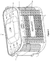
- FIG 1 illustrates an exemplary handheld GNSS device 100.
- Handheld GNSS device 100 utilizes a single housing 102.
- Several GNSS elements are integral to the housing 102 in that they are within the housing or securely mounted thereto. A securely mounted element may be removable.
- Housing 102 allows the user to hold the handheld GNSS device 100 similar to the way one would hold a typical camera.
- the housing 102 may include GNSS antenna cover 104 to cover a GNSS antenna 802 (shown in Figure 8 ) which may receive signals transmitted by a plurality of GNSS satellites and used by handheld GNSS device 100 to determine position.
- the GNSS antenna 802 is integral with the housing 102 in that it resides in the housing 102 under the GNSS antenna cover 104.
- GNSS antenna 802 may receive signals transmitted by at least four GNSS satellites.
- GNSS antenna cover 104 is located on the top side of handheld GNSS device 100.
- An exemplary top side view of the handheld GNSS device 100 is illustrated in Figure 5 .
- Handheld GNSS device 100 further includes covers for communication antennas 106 integral with the housing 102.
- communication antennas 106 there may be three such communication antennas, including GSM, UHF, and WiFi/Bluetooth antennas enclosed beneath covers for the communication antennas 106.
- Communication antennas 806 are positioned beneath the covers 106.
- the GSM and UHF antennas may be only one-way communication antennas. In other words, the GSM and UHF antenna may only be used to receive signals, but not transmit signals.
- the WiFi antenna may allow two-way communication.
- the communication antennas 806 receive positioning assistance data, such as differential correction data or raw positioning data from base transceivers.
- the GNSS antenna cover 104 is located on the top of the housing 102.
- the communication antenna covers 106 are located on the front of the housing 102.
- Handheld GNSS device 100 may further include at least one handgrip 108.
- two handgrips 108 are integral to the housing 102.
- the handgrips 108 may be covered with a rubber material for comfort and to reduce slippage of a user's hands.
- the GNSS antenna cover 104, the communication antenna covers 106 and the handgrips 108 are shown from another view in the exemplary front view illustrated in Figure 7 .
- a front camera lens 110 is located on the front side of the handheld GNSS device 100.
- a second bottom camera lens 116 may be located on the bottom side of the handheld GNSS device 100 in the example shown in Figure 4 .
- the camera included may be a still or video camera.
- the handgrips 108 may also be positioned to be near to the communication antenna covers 106.
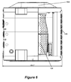
- Handgrips 108 are shown in a position, as in Figure 6 , that, when a user is gripping the handgrips 108, the user minimally interferes with the antenna patterns of GNSS antenna 802 and communication antennas 806. For example, the user's hands do not cause more than -40 dB of interference while gripping the handgrips 108 in this configuration, e.g., with the handgrips 108 behind and off to the side of the communication antenna covers 106.
- handheld GNSS device 100 may further include display 112 for displaying information to assist the user in positioning the device.
- Display 112 may be any electronic display such as a liquid crystal (LCD) display, light emitting diode (LED) display, and the like. Such display devices are well-known by those of ordinary skill in the art and any such device may be used.
- display 112 is integral with the back side of the housing 102 of handheld GNSS device 100.
- Handheld GNSS device 100 may further include a camera for recording still images or video. Such recording devices are well-known by those of ordinary skill in the art and any such device may be used.
- front camera lens 110 is located on the front side of handheld GNSS device 100. A more detailed description of the positioning of front camera lens 110 is provided in US Patent Application No. 12/571,244, filed September 30, 2009 .
- display 112 may be used to display the output of front camera lens 110 .
- handheld GNSS device 100 may also include a second bottom camera lens 116 on the bottom of handheld GNSS device 100 for viewing and alignment of the handheld GNSS device 100 with a point of interest marker.
- the image of the point of interest marker may also be recorded along with the GNSS data to ensure that the GNSS receiver 808 was mounted correctly, or compensate for misalignment later based on the recorded camera information.
- Handheld GNSS device 100 may further include horizon sensors (not shown) for determining the orientation of the device.
- the horizon sensors may be any type of horizon sensor, such as an inclinometer, accelerometer, and the like. Such horizon sensors are well-known by those of ordinary skill in the art and any such device may be used.
- a representation of the output of the horizon sensors may be displayed using display 112. A more detailed description of display 112 is provided below.
- the horizon sensor information can be recorded along with GNSS data to later compensate for mis-leveling of the antenna.
- Handheld GNSS device 100 may further include a distance sensor (not shown) to measure a linear distance.
- the distance sensor may use any range-finding technology, such as sonar, laser, radar, and the like. Such distance sensors are well-known by those of ordinary skill in the art and any such device may be used.
- Figure 4 illustrates a bottom view of the handheld GNSS device 100 according to embodiments of the invention.
- the handheld GNSS device 100 may be mounted on a tripod, or some other support structure, by a mounting structure such as three threaded bushes 114, in some embodiments of the invention.
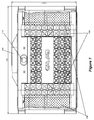
- Figure 8 illustrates an exploded view of the handheld GNSS device 100.
- GNSS antenna 802 is covered by the GNSS antenna cover 104, and the communication antennas 806 are covered by the communication antenna covers 106.
- Figure 9A illustrates an exemplary view 900 of display 112 for positioning handheld GNSS device 100.
- display 112 may display the output of camera.
- the display of the output of camera lens 116 or 110 includes point of interest marker 902.
- point of interest marker 902 is a small circular object identifying a particular location on the ground.
- the location to be measured is located on the ground, and that the point of interest is identifiable by a visible marker ( e.g ., point of interest marker 902).
- the marker may be any object having a small height value. For instance, an "X" painted on the ground or a circular piece of colored paper placed on the point of interest may serve as point of interest marker 902.
- display 112 may further include virtual linear bubble levels 904 and 906 corresponding to the roll and pitch of handheld GNSS device 100, respectively.
- Virtual linear bubble levels 904 and 906 may include virtual bubbles 908 and 910, which identify the amount and direction of roll and pitch of handheld GNSS device 100.
- Virtual linear bubble levels 904 and 906 and virtual bubbles 908 and 910 may be generated by a CPU 1108 and overlaid on the actual image output of the camera.
- positioning of virtual bubbles 908 and 910 in the middle of virtual linear bubble levels 904 and 906 indicate that the device is positioned "horizontally.” As used herein, "horizontally" refers to the orientation whereby the antenna ground plane is parallel to the local horizon.
- data from horizon sensors may be used to generate the linear bubble levels 904 and 906.
- sensor data from horizon sensors may be sent to CPU 1108 which may convert a scaled sensor measurement into a bubble coordinate within virtual linear bubble levels 904 and 906.
- CPU 1108 may then cause the display on display 112 of virtual bubbles 908 and 910 appropriately placed within virtual linear bubble levels 904 and 906.
- virtual linear bubble levels 904 and 906 may act like traditional bubble levels, with virtual bubbles 908 and 910 moving in response to tilting and rolling of handheld GNSS device 100. For example, if handheld GNSS device 100 is tilted forward, virtual bubble 908 may move downwards within virtual linear bubble level 906.
- virtual bubble 908 may move to the right within virtual linear bubble level 904.
- virtual linear bubble levels 904 and 906 are generated by CPU 1108, movement of virtual bubbles 908 and 910 may be programmed to move in any direction in response to movement of handheld GNSS device 100.
- display 112 may further include planar bubble level 912.
- Planar bubble level 912 represents a combination of virtual linear bubble levels 904 and 906 (e.g., placed at the intersection of the virtual bubbles 908 and 910 within the linear levels 904 and 906 ) and may be generated by combining measurements of two orthogonal horizon sensors (not shown). For instance, scaled measurements of horizon sensors may be converted by CPU 1108 into X and Y coordinates on display 112. In one example, measurements from one horizon sensor may be used to generate the X coordinate and measurements from a second horizon sensor may be used to generate the Y coordinate of planar bubble level 912.
- display 112 may further include central crosshair 914.
- central crosshair 914 may be placed in the center of display 112.
- the location of central crosshair 914 may represent the point in display 112 corresponding to the view of front camera lens 110 along optical axis 242.
- placement of planar bubble level 912 within central crosshair 914 may correspond to handheld GNSS device 100 being positioned horizontally.
- Central crosshair 914 may be drawn on the screen of display 112 or may be electronically displayed to display 112.
- Display 112 may be used to aid the user in positioning handheld GNSS device 100 over a point of interest by providing feedback regarding the placement and orientation of the device. For instance, the camera output portion of display 112 provides information to the user regarding the placement of handheld GNSS device 100 with respect to objects on the ground. Additionally, virtual linear bubble levels 904 and 906 provide information to the user regarding the orientation of handheld GNSS device 100 with respect to the horizon. Using at least one of the two types of output displayed on display 112, the user may properly position handheld GNSS device 100 without the use of external positioning equipment.
- both point of interest marker 902 and planar bubble level 912 are shown as off-center from central crosshair 914. This indicates that optical axis 242 of camera lens 110 or 116 is not pointed directly at the point of interest and that the device is not positioned horizontally. If the user wishes to position the device horizontally above a particular point on the ground, the user must center both planar bubble level 912 and point of interest marker 902 within central crosshair 914 as shown in Figure 9B .
- Figure 9B illustrates another exemplary view 920 of display 112.
- virtual linear bubble levels 904 and 906 are shown with their respective virtual bubbles 908 and 910 centered, indicating that the device is horizontal.
- planar bubble level 912 is also centered within central crosshair 914.
- point of interest marker 902 is shown as centered within central crosshair 914. This indicates that optical axis 242 of front camera lens 110 is pointing towards point of interest marker 902.
- handheld GNSS device 100 is positioned horizontally above point of interest marker 902.
- the bottom camera lens 116 or front camera lens 110 can be used to record images of a marker of a known configuration, a point of interest, placed on the ground.
- pixels and linear dimensions of the image are analyzed to estimate a distance to the point of interest.
- Using a magnetic compass or a MEMS gyro in combination with two horizon angles allows the three dimensional orientation of the GNSS handheld device 100 to be determined. Then, the position of the point of interest may be calculated based upon the position of the GNSS antenna 802 through trigonometry.
- a second navigation antenna is coupled to the housing 102 of the GNSS handheld device 100 via an external jack 804 ( Figure 8 ). The second navigation antenna can be used instead of magnetic compass to complete estimation of full three-dimensional attitude along with two dimensional horizon sensors.
- Estimation of a distance to a point of interest can be estimated as described in US Patent Application No. 12/571,244 .
- the bottom camera lens 116 may also be used.
- the measurement is reduced to the calculation of the intersection of at least three cones using equations and methods described in Appendices A, B, and C to this application.
- the misalignment with the survey mark can be recorded and compensated by analyzing the recorded image bitmaps.
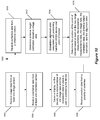
- FIG 10 illustrates an exemplary process 1000 for determining the position of a point of interest using a handheld GNSS device 100 according to embodiments of the invention.
- a user will position the handheld GNSS device 100 such that an image sensor, such as front camera lens 110, obtains image data of the point of interest at 1002.
- Orientation data is received from an orientation sensor of the handheld GNSS device at 1004.
- the image data and the orientation data are displayed on the display 112, such that the user may position the handheld GNSS device 100 to accurately determine the position of the point of interest at 1006.
- the user may position the handheld GNSS device 100 as in the example shown in Figures 9A and 9B .
- position data may be received by the GNSS antenna 802 at 1008.
- Positioning assistance data is also received at 1010 by at least one communication antenna 806.
- the antenna height of the GNSS antenna 802 is a factor in determining the position data of a point of interest marker.
- the point of interest marker position determination takes into account the antenna height in order to determine a more accurate position of the point of interest.
- the optical axis of the bottom camera lens 116 goes through GNSS antenna. After the bottom camera lens 116 records image data of the point of interest marker, at 1012, the antenna height is estimated based on analyzing the image data. For example, by analyzing the size of the point of interest marker in the image, a height of the GNSS antenna 802 can be estimated.
- a misalignment of the handheld GNSS device 100 may add to an error in position determination of the point of interest marker.
- the user using the handheld GNSS device 100 may not have aligned the handheld GNSS device 100 with the point of interest marker exactly, which could affect the accuracy of the position determination of the point of interest.
- an alignment error associated with the handheld GNSS device 100 in relation to the point of interest is determined.
- the position data associated with the point of interest is determined using at least the image data, the orientation data, the position data, the position assistance data, the antenna height estimation, and the alignment error.
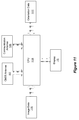
- Figure 11 illustrates an exemplary logic diagram showing the relationships between the various components of handheld GNSS device 100.
- GNSS antenna 802 may send position data received from GNSS satellites to receiver 808.
- Receiver 808 may convert the received GNSS satellite signals into Earth-based coordinates, such as WGS84, ECEF, ENU, and the like.
- GNSS receiver 808 may further send the coordinates to CPU 1108 for processing along with position assistance data received from communication antennas 806.
- Communication antennas 806 are connected to a communication board 810.
- Orientation data 1112 may also be sent to CPU 1108.
- Orientation data 1112 may include pitch data from pitch horizon sensors and roll data from roll horizon sensors, for example.
- Image data 1110 from video or still camera may also be sent along to the CPU 1108 with the position data received by the GNSS antenna 802, positioning assistance data received by communication antenna 106, and orientation data 1112.
- Distance data from a distance sensor may also be used by CPU 1108.
- CPU 1108 processes the data to determine the position of the point of interest marker and provides display data to be displayed on display 112.
- FIG. 12 illustrates an exemplary computing system 1200 that may be employed to implement processing functionality for various aspects of the current technology (e.g., as a GNSS device, receiver, CPU 1108, activity data logic/database, combinations thereof, and the like.).
- Computing system 1200 may represent, for example, a user device such as a desktop, mobile phone, geodesic device, and so on as may be desirable or appropriate for a given application or environment.
- Computing system 1200 can include one or more processors, such as a processor 1204.
- Processor 1204 can be implemented using a general or special purpose processing engine such as, for example, a microprocessor, microcontroller or other control logic. In this example, processor 1204 is connected to a bus 1202 or other communication medium.
- Computing system 1200 can also include a main memory 1208, such as random access memory (RAM) or other dynamic memory, for storing information and instructions to be executed by processor 1204.
- Main memory 1208 also may be used for storing temporary variables or other intermediate information during execution of instructions to be executed by processor 1204.
- Computing system 1200 may likewise include a read only memory (“ROM”) or other static storage device coupled to bus 1202 for storing static information and instructions for processor 1204.
- ROM read only memory
- the computing system 1200 may also include information storage mechanism 1210, which may include, for example, a media drive 1212 and a removable storage interface 1220.
- the media drive 1212 may include a drive or other mechanism to support fixed or removable storage media, such as a hard disk drive, a floppy disk drive, a magnetic tape drive, an optical disk drive, a CD or DVD drive (R or RW), or other removable or fixed media drive.
- Storage media 1218 may include, for example, a hard disk, floppy disk, magnetic tape, optical disk, CD or DVD, or other fixed or removable medium that is read by and written to by media drive 1212. As these examples illustrate, the storage media 1218 may include a computer-readable storage medium having stored therein particular computer software or data.
- information storage mechanism 1210 may include other similar instrumentalities for allowing computer programs or other instructions or data to be loaded into computing system 1200.
- Such instrumentalities may include, for example, a removable storage unit 1222 and an interface 1220, such as a program cartridge and cartridge interface, a removable memory (for example, a flash memory or other removable memory module) and memory slot, and other removable storage units 1222 and interfaces 1220 that allow software and data to be transferred from the removable storage unit 1222 to computing system 1200.
- Computing system 1200 can also include a communications interface 1224.
- Communications interface 1224 can be used to allow software and data to be transferred between computing system 1200 and external devices.
- Examples of communications interface 1224 can include a modem, a network interface (such as an Ethernet or other NIC card), a communications port (such as for example, a USB port), a PCMCIA slot and card, etc.
- Some examples of a channel include a phone line, a cellular phone link, an RF link, a network interface, a local or wide area network, and other communications channels.
- computer program product and “computer-readable storage medium” may be used generally to refer to media such as, for example, memory 1208, storage media 1218, or removable storage unit 1222. These and other forms of computer-readable media may be involved in providing one or more sequences of one or more instructions to processor 1204 for execution. Such instructions, generally referred to as "computer program code” (which may be grouped in the form of computer programs or other groupings), when executed, enable the computing system 1200 to perform features or functions of embodiments of the current technology.
- the software may be stored in a computer-readable medium and loaded into computing system 1200 using, for example, removable storage drive 1222, media drive 1212 or communications interface 1224.
- the control logic in this example, software instructions or computer program code
- the processor 1204 when executed by the processor 1204, causes the processor 1204 to perform the functions of the technology as described herein.
Description
- The present invention relates to a portable Global Navigation Satellite System (GNSS), including Global Positioning System (GPS), GLONASS, Galileo, and other satellite navigation and positioning systems.
- Today, the number of applications utilizing GNSS information is rapidly increasing. For example, GNSS information is a valuable tool for geodesists. Geodesists commonly use GNSS devices to determine the location of a point of interest anywhere on, or in the vicinity of, the Earth. Often, these points of interest are located at remote destinations which are difficult to access. Thus, compact, easy-to-carry positioning devices are desired.
- GNSS receivers work by receiving data from GNSS satellites. To achieve millimeter and centimeter level accuracy, at least two GNSS receivers are needed. One receiver is positioned at a site where the position is known. A second receiver is positioned at a site whose position needs to be determined. The measurement from the first receiver is used to correct GNSS system errors at the second receiver. In post-processed mode, the data from both receivers can be stored and then transferred to a computer for processing. Alternatively, the corrections from the first receiver, the known receiver, may be transmitted in real time (via radio modems, Global System for Mobile Communications (GSM), etc.) to the unknown receiver, and the accurate position of the unknown receiver determined in real time.
- A GNSS receiver typically includes a GNSS antenna, a signal processing section, a display and control section, a data communications section (for real-time processing), a battery, and a charger. Some degree of integration of these sections is usually desired for a handheld portable unit.
- Another challenge of portable GNSS units is precisely positioning a GNSS antenna on the point of interest for location measurement. Previously, bulky equipment such as a separate tripod or other external hardware was used to "level" the antenna. In other systems, light low-precision antennas were used. Such devices are bulky and difficult to carry. Thus, even as portable GNSS positioning devices become more compact, they suffer from the drawback of requiring additional bulky positioning equipment.
US2003090415 discloses a GPS positioning system which comprises a fixed station and a mobile station. The mobile station has: positional positioning means; imaging means; direction detecting means; and arithmetic processing means. The positional positioning means measures positional coordinates by receiving radio wave from a satellite. The imaging means is arranged in a predetermined position for the GPS positional positioning means. A disadvantage with this system is that it comprises several parts including a mobile station and a fixed station and that the system is difficult to carry. - Thus, for high-precision applications, the use of multiple units to house the various components required for prior GNSS systems, and the requirement for cables and connectors to couple the units, creates problems regarding portability, reliability, and durability. In addition, the systems are expensive to manufacture and assemble.
WO2006070047 concerns an electronic device for providing information concerning one or more targets, relative to which target the device is to be aligned in a set manner. By pointing the target by the device, the desired target can be sought or define the location of the target, by applying defining means. In certain situations there may be a need for higher reliability in precision position measurements. - Therefore, a high precision, portable, complete handheld GNSS device that overcomes these disadvantages of conventional devices is desired.
- Embodiments of the present disclosure are directed to a handheld GNSS device for determining position data for a point of interest. The device includes a housing, handgrips integral to the housing for enabling a user to hold the device, and a display screen integral with the housing for displaying image data and orientation data to assist a user in positioning the device. The device further includes a GNSS antenna and at least one communication antenna, both integral with the housing. The GNSS antenna receives position data from a plurality of satellites. One or more communication antennas receive positioning assistance data related to the position data from a base station. The GNSS antenna has a first antenna pattern, and the at least one communication antenna has a second antenna pattern. The GNSS antenna and the communication antenna(s) are configured such that the first and second antenna patterns are substantially separated.
- Coupled to the GNSS antenna, within the housing, is at least one receiver. Further, the device includes, within the housing, orientation circuitry for generating orientation data of the housing based upon a position of the housing related to the horizon, imaging circuitry for obtaining image data concerning the point of interest for display on the display screen, and positioning circuitry, coupled to the at least one receiver, the imaging circuitry, and the orientation circuitry, for determining a position for the point of interest based on at least the position data, the positioning assistance data, the orientation data, and the image data.
-
-
Figure 1 illustrates a perspective view of a handheld GNSS device according to embodiments of the invention; -
Figure 2 illustrates another perspective view of a handheld GNSS device according to embodiments of the invention; -
Figure 3 illustrates a back view of a handheld GNSS device including a display screen for a user according to embodiments of the invention; -
Figure 4 illustrates a bottom view of a handheld GNSS device according to embodiments of the invention; -
Figure 5 illustrates a top view of a handheld GNSS device according to embodiments of the invention; -
Figure 6 illustrates a side view of a handheld GNSS device including handgrips for a user according to embodiments of the invention; -
Figure 7 illustrates a front view of a handheld GNSS device including a viewfinder for a camera according to embodiments of the invention; -
Figure 8 illustrates an exploded view of a handheld GNSS device including a viewfinder for a camera according to embodiments of the invention; -
Figure 9A illustrates an exemplary view of the display screen of a handheld GNSS device including elements used for positioning the device; -
Figure 9B illustrates another exemplary view of the display screen of a GNSS handheld device oriented horizontally and above a point of interest; -
Figure 10 illustrates a flowchart of a method for measuring position using a handheld GNSS device according to embodiments of the invention; -
Figure 11 illustrates a logic diagram showing the relationships between the various components of a handheld GNSS device according to embodiments of the invention; and -
Figure 12 illustrates a typical computing system that may be employed to implement some or all of the processing functionality in certain embodiments. - In the following description, reference is made to the accompanying drawings which form a part thereof, and which illustrate several embodiments of the present invention. It is understood that other embodiments may be utilized and structural and operational changes may be made without departing from the scope of the present invention. The use of the same reference symbols in different drawings indicates similar or identical items.
- The following description is presented to enable a person of ordinary skill in the art to make and use the various embodiments. Descriptions of specific devices, techniques, and applications are provided only as examples. Various modifications to the examples described herein will be readily apparent to those of ordinary skill in the art, and the general principles defined herein may be applied to other examples and applications. Thus, the various embodiments are not intended to be limited to the examples described herein and shown, but are to be accorded the scope consistent with the claims.
- Embodiments of the invention relate to mounting a GNSS antenna and communication antennas in a single housing. The communication antennas are for receiving differential correction data from a fixed or mobile base transceiver, as described in
U.S. Patent Application No. 12/360,808 , assigned to the assignee of the present invention. Differential correction data may include, for example, the difference between measured satellite pseudo-ranges and actual pseudo-ranges. This correction data received from a base station may help to eliminate errors in the GNSS data received from the satellites. Alternatively, or in addition, the communication antenna may receive raw range data from a moving base transceiver. Raw positioning data received by the communication antenna may be, for example, coordinates of the base and other raw data, such as the carrier phase of a satellite signal received at the base transceiver and the pseudo-range of the satellite to the base transceiver. - Additionally, a second navigation antenna may be connected to the handheld GNSS device to function as the primary navigation antenna if the conditions and/or orientation do not allow the first GNSS antenna to receive a strong GNSS signal.
- The communication antenna is configured such that its antenna pattern is substantially separated from the antenna pattern of the GNSS antenna such that there is minimal or nearly minimal mutual interference between the antennas. As used herein, "substantial" separation may be achieved by positioning the communication antenna below the main ground plane of the GNSS antenna, as shown in
Figure 1 . According to embodiments of the invention, a substantial separation attenuates interference between the communication antenna and the GNSS antenna by as much as 40 dB. Furthermore, the communication antenna and the GNSS antenna are positioned such that the body of the user holding the GNSS device does not substantially interfere with the GNSS signal. - Moreover, as mentioned above, to properly measure the position of a given point using a GNSS-based device, the GNSS antenna must be precisely positioned so that the position of the point of interest may be accurately determined. To position a GNSS device in such a manner, external hardware, such as a tripod, is commonly used. Such hardware is bulky and difficult to carry. Thus, according to embodiments of the invention, compact positioning tools, included in the single unit housing, are useful for a portable handheld GNSS device.
- As such, various embodiments are described below relating to a handheld GNSS device. The handheld GNSS device may include various sensors, such as a camera, distance sensor, and horizon sensors. A display element may also be included for assisting a user to position the device without the aid of external positioning equipment (e.g., a tripod or pole).
-
Figure 1 illustrates an exemplaryhandheld GNSS device 100.Handheld GNSS device 100 utilizes asingle housing 102. Several GNSS elements are integral to thehousing 102 in that they are within the housing or securely mounted thereto. A securely mounted element may be removable.Housing 102 allows the user to hold thehandheld GNSS device 100 similar to the way one would hold a typical camera. In one example, thehousing 102 may includeGNSS antenna cover 104 to cover a GNSS antenna 802 (shown inFigure 8 ) which may receive signals transmitted by a plurality of GNSS satellites and used byhandheld GNSS device 100 to determine position. TheGNSS antenna 802 is integral with thehousing 102 in that it resides in thehousing 102 under theGNSS antenna cover 104. - In one example,
GNSS antenna 802 may receive signals transmitted by at least four GNSS satellites. In the example shown byFigure 1 ,GNSS antenna cover 104 is located on the top side ofhandheld GNSS device 100. An exemplary top side view of thehandheld GNSS device 100 is illustrated inFigure 5 . -
Handheld GNSS device 100 further includes covers forcommunication antennas 106 integral with thehousing 102. In embodiments of the invention there may be three such communication antennas, including GSM, UHF, and WiFi/Bluetooth antennas enclosed beneath covers for thecommunication antennas 106. - An exemplary exploded view of
handheld GNSS device 100 is shown inFigure 8 .Communication antennas 806 are positioned beneath thecovers 106. The GSM and UHF antennas may be only one-way communication antennas. In other words, the GSM and UHF antenna may only be used to receive signals, but not transmit signals. The WiFi antenna may allow two-way communication. Thecommunication antennas 806 receive positioning assistance data, such as differential correction data or raw positioning data from base transceivers. - In the example shown in
Figure 1 , theGNSS antenna cover 104 is located on the top of thehousing 102. In the same example ofFigure 1 , the communication antenna covers 106 are located on the front of thehousing 102. -
Handheld GNSS device 100 may further include at least onehandgrip 108. In the example shown inFigure 1 , twohandgrips 108 are integral to thehousing 102. Thehandgrips 108 may be covered with a rubber material for comfort and to reduce slippage of a user's hands. - The
GNSS antenna cover 104, the communication antenna covers 106 and thehandgrips 108 are shown from another view in the exemplary front view illustrated inFigure 7 . Afront camera lens 110 is located on the front side of thehandheld GNSS device 100. A secondbottom camera lens 116 may be located on the bottom side of thehandheld GNSS device 100 in the example shown inFigure 4 . The camera included may be a still or video camera. - The
handgrips 108, in certain embodiments, may also be positioned to be near to the communication antenna covers 106.Handgrips 108 are shown in a position, as inFigure 6 , that, when a user is gripping thehandgrips 108, the user minimally interferes with the antenna patterns ofGNSS antenna 802 andcommunication antennas 806. For example, the user's hands do not cause more than -40 dB of interference while gripping thehandgrips 108 in this configuration, e.g., with thehandgrips 108 behind and off to the side of the communication antenna covers 106. - As shown in
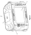
Figure 2 andFigure 3 ,handheld GNSS device 100 may further includedisplay 112 for displaying information to assist the user in positioning the device.Display 112 may be any electronic display such as a liquid crystal (LCD) display, light emitting diode (LED) display, and the like. Such display devices are well-known by those of ordinary skill in the art and any such device may be used. In the example shown byFigure 2 ,display 112 is integral with the back side of thehousing 102 ofhandheld GNSS device 100. -
Handheld GNSS device 100 may further include a camera for recording still images or video. Such recording devices are well-known by those of ordinary skill in the art and any such device may be used. In the example illustrated inFigure 1 ,front camera lens 110 is located on the front side ofhandheld GNSS device 100. A more detailed description of the positioning offront camera lens 110 is provided inUS Patent Application No. 12/571,244, filed September 30, 2009 display 112 may be used to display the output offront camera lens 110. - With reference to
Figure 4 ,handheld GNSS device 100 may also include a secondbottom camera lens 116 on the bottom ofhandheld GNSS device 100 for viewing and alignment of thehandheld GNSS device 100 with a point of interest marker. The image of the point of interest marker may also be recorded along with the GNSS data to ensure that theGNSS receiver 808 was mounted correctly, or compensate for misalignment later based on the recorded camera information. -
Handheld GNSS device 100 may further include horizon sensors (not shown) for determining the orientation of the device. The horizon sensors may be any type of horizon sensor, such as an inclinometer, accelerometer, and the like. Such horizon sensors are well-known by those of ordinary skill in the art and any such device may be used. In one example, a representation of the output of the horizon sensors may be displayed usingdisplay 112. A more detailed description ofdisplay 112 is provided below. The horizon sensor information can be recorded along with GNSS data to later compensate for mis-leveling of the antenna. -
Handheld GNSS device 100 may further include a distance sensor (not shown) to measure a linear distance. The distance sensor may use any range-finding technology, such as sonar, laser, radar, and the like. Such distance sensors are well-known by those of ordinary skill in the art and any such device may be used. -
Figure 4 illustrates a bottom view of thehandheld GNSS device 100 according to embodiments of the invention. Thehandheld GNSS device 100 may be mounted on a tripod, or some other support structure, by a mounting structure such as three threadedbushes 114, in some embodiments of the invention. -
Figure 8 illustrates an exploded view of thehandheld GNSS device 100. When assembled,GNSS antenna 802 is covered by theGNSS antenna cover 104, and thecommunication antennas 806 are covered by the communication antenna covers 106. -
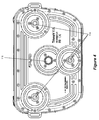
Figure 9A illustrates anexemplary view 900 ofdisplay 112 for positioninghandheld GNSS device 100. In one example,display 112 may display the output of camera. In this example, the display of the output ofcamera lens interest marker 902. As shown inFigure 9A , point ofinterest marker 902 is a small circular object identifying a particular location on the ground. In the examples provided herein, we assume that the location to be measured is located on the ground, and that the point of interest is identifiable by a visible marker (e.g., point of interest marker 902). The marker may be any object having a small height value. For instance, an "X" painted on the ground or a circular piece of colored paper placed on the point of interest may serve as point ofinterest marker 902. - In another example,
display 112 may further include virtuallinear bubble levels handheld GNSS device 100, respectively. Virtuallinear bubble levels virtual bubbles handheld GNSS device 100. Virtuallinear bubble levels virtual bubbles CPU 1108 and overlaid on the actual image output of the camera. In one example, positioning ofvirtual bubbles linear bubble levels - In one example, data from horizon sensors may be used to generate the
linear bubble levels CPU 1108 which may convert a scaled sensor measurement into a bubble coordinate within virtuallinear bubble levels CPU 1108 may then cause the display ondisplay 112 ofvirtual bubbles linear bubble levels linear bubble levels virtual bubbles handheld GNSS device 100. For example, ifhandheld GNSS device 100 is tilted forward,virtual bubble 908 may move downwards within virtuallinear bubble level 906. Additionally, ifhandheld GNSS device 100 is rolled to the left,virtual bubble 908 may move to the right within virtuallinear bubble level 904. However, since virtuallinear bubble levels CPU 1108, movement ofvirtual bubbles handheld GNSS device 100. - In another example,
display 112 may further includeplanar bubble level 912.Planar bubble level 912 represents a combination of virtuallinear bubble levels 904 and 906 (e.g., placed at the intersection of thevirtual bubbles linear levels 904 and 906) and may be generated by combining measurements of two orthogonal horizon sensors (not shown). For instance, scaled measurements of horizon sensors may be converted byCPU 1108 into X and Y coordinates ondisplay 112. In one example, measurements from one horizon sensor may be used to generate the X coordinate and measurements from a second horizon sensor may be used to generate the Y coordinate ofplanar bubble level 912. - As shown in
Figure 9A ,display 112 may further includecentral crosshair 914. In one example,central crosshair 914 may be placed in the center ofdisplay 112. In another example, the location ofcentral crosshair 914 may represent the point indisplay 112 corresponding to the view offront camera lens 110 along optical axis 242. In yet another example, placement ofplanar bubble level 912 withincentral crosshair 914 may correspond tohandheld GNSS device 100 being positioned horizontally.Central crosshair 914 may be drawn on the screen ofdisplay 112 or may be electronically displayed to display 112. -
Display 112 may be used to aid the user in positioninghandheld GNSS device 100 over a point of interest by providing feedback regarding the placement and orientation of the device. For instance, the camera output portion ofdisplay 112 provides information to the user regarding the placement ofhandheld GNSS device 100 with respect to objects on the ground. Additionally, virtuallinear bubble levels handheld GNSS device 100 with respect to the horizon. Using at least one of the two types of output displayed ondisplay 112, the user may properly positionhandheld GNSS device 100 without the use of external positioning equipment. - In the example illustrated by
Figure 9A , both point ofinterest marker 902 andplanar bubble level 912 are shown as off-center fromcentral crosshair 914. This indicates that optical axis 242 ofcamera lens planar bubble level 912 and point ofinterest marker 902 withincentral crosshair 914 as shown inFigure 9B . -
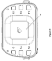
Figure 9B illustrates anotherexemplary view 920 ofdisplay 112. In this example, virtuallinear bubble levels virtual bubbles planar bubble level 912 is also centered withincentral crosshair 914. Additionally, in this example, point ofinterest marker 902 is shown as centered withincentral crosshair 914. This indicates that optical axis 242 offront camera lens 110 is pointing towards point ofinterest marker 902. Thus, in the example shown byFigure 9B ,handheld GNSS device 100 is positioned horizontally above point ofinterest marker 902. - The
bottom camera lens 116 orfront camera lens 110 can be used to record images of a marker of a known configuration, a point of interest, placed on the ground. In one application, pixels and linear dimensions of the image are analyzed to estimate a distance to the point of interest. Using a magnetic compass or a MEMS gyro in combination with two horizon angles allows the three dimensional orientation of theGNSS handheld device 100 to be determined. Then, the position of the point of interest may be calculated based upon the position of theGNSS antenna 802 through trigonometry. In one embodiment, a second navigation antenna is coupled to thehousing 102 of theGNSS handheld device 100 via an external jack 804 (Figure 8 ). The second navigation antenna can be used instead of magnetic compass to complete estimation of full three-dimensional attitude along with two dimensional horizon sensors. - Estimation of a distance to a point of interest can be estimated as described in
US Patent Application No. 12/571,244 bottom camera lens 116 may also be used. The measurement is reduced to the calculation of the intersection of at least three cones using equations and methods described in Appendices A, B, and C to this application. - If the optical axis of the camera is not pointing directly at the point of interest, the misalignment with the survey mark can be recorded and compensated by analyzing the recorded image bitmaps.
-
Figure 10 illustrates anexemplary process 1000 for determining the position of a point of interest using ahandheld GNSS device 100 according to embodiments of the invention. With reference toFigure 1 , a user will position thehandheld GNSS device 100 such that an image sensor, such asfront camera lens 110, obtains image data of the point of interest at 1002. Orientation data is received from an orientation sensor of the handheld GNSS device at 1004. The image data and the orientation data are displayed on thedisplay 112, such that the user may position thehandheld GNSS device 100 to accurately determine the position of the point of interest at 1006. The user may position thehandheld GNSS device 100 as in the example shown inFigures 9A and 9B . - When the
handheld GNSS device 100 is positioned to accurately determine the position of the point of interest, position data may be received by theGNSS antenna 802 at 1008. Positioning assistance data is also received at 1010 by at least onecommunication antenna 806. - The antenna height of the
GNSS antenna 802 is a factor in determining the position data of a point of interest marker. The point of interest marker position determination takes into account the antenna height in order to determine a more accurate position of the point of interest. The optical axis of thebottom camera lens 116 goes through GNSS antenna. After thebottom camera lens 116 records image data of the point of interest marker, at 1012, the antenna height is estimated based on analyzing the image data. For example, by analyzing the size of the point of interest marker in the image, a height of theGNSS antenna 802 can be estimated. - Further, a misalignment of the
handheld GNSS device 100 may add to an error in position determination of the point of interest marker. The user using thehandheld GNSS device 100 may not have aligned thehandheld GNSS device 100 with the point of interest marker exactly, which could affect the accuracy of the position determination of the point of interest. As such, at 1014, an alignment error associated with thehandheld GNSS device 100 in relation to the point of interest is determined. - Then, at 1016, the position data associated with the point of interest is determined using at least the image data, the orientation data, the position data, the position assistance data, the antenna height estimation, and the alignment error.
-
Figure 11 illustrates an exemplary logic diagram showing the relationships between the various components ofhandheld GNSS device 100. In one example,GNSS antenna 802 may send position data received from GNSS satellites toreceiver 808.Receiver 808 may convert the received GNSS satellite signals into Earth-based coordinates, such as WGS84, ECEF, ENU, and the like.GNSS receiver 808 may further send the coordinates toCPU 1108 for processing along with position assistance data received fromcommunication antennas 806.Communication antennas 806 are connected to acommunication board 810.Orientation data 1112 may also be sent toCPU 1108.Orientation data 1112 may include pitch data from pitch horizon sensors and roll data from roll horizon sensors, for example.Image data 1110 from video or still camera may also be sent along to theCPU 1108 with the position data received by theGNSS antenna 802, positioning assistance data received bycommunication antenna 106, andorientation data 1112. Distance data from a distance sensor may also be used byCPU 1108.CPU 1108 processes the data to determine the position of the point of interest marker and provides display data to be displayed ondisplay 112. -
Figure 12 illustrates an exemplary computing system 1200 that may be employed to implement processing functionality for various aspects of the current technology (e.g., as a GNSS device, receiver,CPU 1108, activity data logic/database, combinations thereof, and the like.). Those skilled in the relevant art will also recognize how to implement the current technology using other computer systems or architectures. Computing system 1200 may represent, for example, a user device such as a desktop, mobile phone, geodesic device, and so on as may be desirable or appropriate for a given application or environment. Computing system 1200 can include one or more processors, such as aprocessor 1204.Processor 1204 can be implemented using a general or special purpose processing engine such as, for example, a microprocessor, microcontroller or other control logic. In this example,processor 1204 is connected to abus 1202 or other communication medium. - Computing system 1200 can also include a
main memory 1208, such as random access memory (RAM) or other dynamic memory, for storing information and instructions to be executed byprocessor 1204.Main memory 1208 also may be used for storing temporary variables or other intermediate information during execution of instructions to be executed byprocessor 1204. Computing system 1200 may likewise include a read only memory ("ROM") or other static storage device coupled tobus 1202 for storing static information and instructions forprocessor 1204. - The computing system 1200 may also include
information storage mechanism 1210, which may include, for example, amedia drive 1212 and aremovable storage interface 1220. The media drive 1212 may include a drive or other mechanism to support fixed or removable storage media, such as a hard disk drive, a floppy disk drive, a magnetic tape drive, an optical disk drive, a CD or DVD drive (R or RW), or other removable or fixed media drive.Storage media 1218 may include, for example, a hard disk, floppy disk, magnetic tape, optical disk, CD or DVD, or other fixed or removable medium that is read by and written to bymedia drive 1212. As these examples illustrate, thestorage media 1218 may include a computer-readable storage medium having stored therein particular computer software or data. - In alternative embodiments,
information storage mechanism 1210 may include other similar instrumentalities for allowing computer programs or other instructions or data to be loaded into computing system 1200. Such instrumentalities may include, for example, a removable storage unit 1222 and aninterface 1220, such as a program cartridge and cartridge interface, a removable memory (for example, a flash memory or other removable memory module) and memory slot, and other removable storage units 1222 andinterfaces 1220 that allow software and data to be transferred from the removable storage unit 1222 to computing system 1200. - Computing system 1200 can also include a
communications interface 1224. Communications interface 1224 can be used to allow software and data to be transferred between computing system 1200 and external devices. Examples ofcommunications interface 1224 can include a modem, a network interface (such as an Ethernet or other NIC card), a communications port (such as for example, a USB port), a PCMCIA slot and card, etc. Software and data transferred viacommunications interface 1224. Some examples of a channel include a phone line, a cellular phone link, an RF link, a network interface, a local or wide area network, and other communications channels. - In this document, the terms "computer program product" and "computer-readable storage medium" may be used generally to refer to media such as, for example,
memory 1208,storage media 1218, or removable storage unit 1222. These and other forms of computer-readable media may be involved in providing one or more sequences of one or more instructions toprocessor 1204 for execution. Such instructions, generally referred to as "computer program code" (which may be grouped in the form of computer programs or other groupings), when executed, enable the computing system 1200 to perform features or functions of embodiments of the current technology. - In an embodiment where the elements are implemented using software, the software may be stored in a computer-readable medium and loaded into computing system 1200 using, for example, removable storage drive 1222, media drive 1212 or
communications interface 1224. The control logic (in this example, software instructions or computer program code), when executed by theprocessor 1204, causes theprocessor 1204 to perform the functions of the technology as described herein. - It will be appreciated that, for clarity purposes, the above description has described embodiments with reference to different functional units and processors. However, it will be apparent that any suitable distribution of functionality between different functional units, processors, or domains may be used. For example, functionality illustrated to be performed by separate processors or controllers may be performed by the same processor or controller. Hence, references to specific functional units are only to be seen as references to suitable means for providing the described functionality, rather than indicative of a strict logical or physical structure or organization.
- Furthermore, although individually listed, a plurality of means, elements, or method steps may be implemented by, for example, a single unit or processor. Additionally, although individual features may be included in different claims, these may possibly be advantageously combined, and the inclusion in different claims does not imply that a combination of features is not feasible or advantageous. Also, the inclusion of a feature in one category of claims does not imply a limitation to this category, but rather the feature may be equally applicable to other claim categories, as appropriate.
- Although a feature may appear to be described in connection with a particular embodiment, one skilled in the art would recognize that various features of the described embodiments may be combined. Moreover, aspects described in connection with an embodiment may stand alone.
- Below are some aspects of the invention disclosed herein.
-
Aspect 1. An apparatus for determining position data for a point of interest, comprising:- a housing;
- at least one handgrip, integral with the housing, for enabling a user to hold the apparatus;
- a display screen, integral with the housing, for displaying image data and orientation data to assist a user in positioning the apparatus;
- a GNSS antenna, integral with the housing, and having a first pattern for receiving position data from a plurality of satellites;
- at least one communication antenna, integral with the housing for receiving positioning assistance data related to the position data from a base station, wherein the at least one communication antenna has a second pattern, and the GNSS antenna and the at least one communication antenna are configured such that the first and second patterns are substantially separated;
- at least one receiver within the housing and coupled to the GNSS antenna;
- orientation circuitry, within the housing, for generating orientation data of the housing based upon a position of the housing related to the horizon;
- imaging circuitry, within the housing, for obtaining image data concerning the point of interest for display on the display screen; and
- positioning circuitry, coupled to the at least one receiver, the imaging circuitry, and the orientation circuitry, for determining a position for the point of interest based on at least the position data, the positioning assistance data, the orientation data, and the image data.
- Aspect 2. The apparatus of
aspect 1, wherein the at least one communication antenna is an antenna selected from a group consisting of: a GSM antenna, a UHF antenna, and a WiFi/Bluetooth antenna. -
Aspect 3. The apparatus ofaspect 1, wherein the at least one communication antenna comprises three communication antennas. - Aspect 4. The apparatus of
aspect 1, wherein the orientation of the GNSS antenna is substantially orthogonal to the display. - Aspect 5. The apparatus of
aspect 1, further comprising a GNSS antenna connector, integral with the housing, for connecting a second GNSS antenna. - Aspect 6. The apparatus of
aspect 1, wherein the at least one handgrip enables the user to hold the apparatus at substantially the user's eye level. - Aspect 7. The apparatus of
aspect 1, further comprising a monopod connector. - Aspect 8. The apparatus of
aspect 1, further comprising a shoulder strap. - Aspect 9. The apparatus of
aspect 1, wherein the positioning assistance data includes raw position data of the base station for comparing with the position data received by the GNSS antenna to determine the position of the point of interest. - Aspect 10. The apparatus of
aspect 1, wherein the positioning assistance data includes correction data for compensating for errors in the position data in determining the position of the point of interest. - Aspect 11. The apparatus of
aspect 1, wherein the at least one handgrip is positioned with respect to the at least one communication antenna to enable a user to grasp the at least one handgrip without substantially interfering with receiving the positioning assistance data by the at least one communication antenna. - Aspect 12. The apparatus of
aspect 1, wherein the imaging circuitry includes an optical sensor, integral with the housing, for acquiring image data of the point of interest, wherein the image data is stored in a memory. - Aspect 13. The apparatus of aspect 12, wherein the image data includes information about the point of interest to determine orientation and position data of the apparatus.
- Aspect 14. The apparatus of
aspect 1, wherein a GNSS antenna cover of the housing is transparent to a GNSS signal. - Aspect 15. The apparatus of
aspect 1, wherein the display screen is integral with the housing such that the display screen faces the user when the user uses the apparatus. - Aspect 16. The apparatus of
aspect 1, further comprising:- a headset;
- a speaker; and
- a microphone.
- Aspect 17. The apparatus of aspect 16, wherein the imaging circuitry and the microphone begin operating without a user input.
- Aspect 18. The apparatus of aspect 17, wherein the microphone is operable for recording voice comments from the user.
- Aspect 19. The apparatus of
aspect 1, further comprising an orientation indicator, integral with the housing, for assisting the user in positioning the apparatus relative to the point of interest. -
Aspect 20. The apparatus ofaspect 1, wherein the image data includes at least one image, and the at least one image represents a view of the point of interest viewed from the apparatus. - Aspect 21. The apparatus of
aspect 1, wherein the orientation data represents an orientation of the apparatus with respect to a plane parallel with a horizon. - Aspect 22. A computer-implemented method for determining a position of a point of interest by a handheld device, the computer-implemented method comprising:
- receiving image data from at least one image sensor;
- receiving orientation data from at least one orientation sensor;
- causing a display, on the device, of a representation of the image data and the orientation data to assist a user in positioning the device;
- receiving position data, by a GNSS antenna, from a plurality of satellites;
- receiving positioning assistance data, by at least one communication antenna, from a reference station;
- determining a GNSS antenna height estimation based on the image data;
- determining an alignment error associated with the handheld device and the point of interest based on the image data; and
- determining a position of the point of interest based at least on the position data, the positioning assistance data, the orientation data, the antenna height estimation, and the alignment error.
- Aspect 23. The computer-implemented method of aspect 22, wherein the GNSS antenna height estimation is determined based on analyzing pixels of the image data.
- Aspect 24. The computer-implemented method of aspect 22, wherein the alignment error is determined based on analyzing pixels of the image data.
-
Aspect 25. The computer-implemented method of aspect 22, wherein the positioning assistance data includes raw position data of the base station for comparing with the position data received by the GNSS antenna to determine the position of the point of interest. - Aspect 26. The computer-implemented method of aspect 22, wherein the positioning assistance data includes correction data for compensating for errors in the position data in determining the position of the point of interest.
- Aspect 27. A computer-readable medium encoded with executable instructions for determining a position of a point of interest by a handheld device, the instructions comprising instructions for:
- receiving image data from at least one image sensor;
- receiving orientation data from at least one orientation sensor;
- causing a display, on the device, of a representation of the image data and the orientation data to assist a user in positioning the device;
- receiving position data, by a GNSS antenna, from a plurality of satellites;
- receiving positioning assistance data, by at least one communication antenna, from a reference station;
- determining a GNSS antenna height estimation based on the image data;
- determining an alignment error associated with the handheld device and the point of interest based on the image data; and
- determining a position of the point of interest based at least on the position data, the positioning assistance data, the orientation data, the antenna height estimation, and the alignment error.
- Aspect 28. The computer-readable medium of aspect 27, wherein the GNSS antenna height estimation is determined based on analyzing pixels of the image data.
- Aspect 29. The computer-readable medium of aspect 27, wherein the alignment error is determined based on analyzing pixels of the image data.
- Aspect 30. The computer-readable medium of aspect 27, wherein the positioning assistance data includes raw position data of the base station for comparing with the position data received by the GNSS antenna to determine the position of the point of interest.
- Aspect 31. The computer-readable medium of aspect 27, wherein the positioning assistance data includes correction data for compensating for errors in the position data in determining the position of the point of interest.
Claims (14)
- An apparatus (100) for determining position data for a point of interest, comprising:a housing (102);characterized in that it further comprises:at least one handgrip (108), integral with the housing (102), for enabling a user to hold the apparatus; (100) a display screen (112), integral with the housing (102), for displaying image data (1110) and orientation data (1112) to assist a user in positioning the apparatus; (100)a GNSS antenna (802), integral with the housing (102), for receiving position data from a plurality of satellites;at least one communication antenna (806), integral with the housing (102), for receiving positioning assistance data related to the position data from a base station;at least one receiver (808) within the housing (102), and coupled to the GNSS antenna (802);orientation circuitry, within the housing (102), for generating orientation data (1112) of the housing (102), based upon a position of the housing (102), related to the horizon;imaging circuitry (116), within the housing (102), for obtaining image data (1110) concerning the point of interest for display on the display screen (112); and positioning circuitry (1108), coupled to the at least one receiver (808), the imaging circuitry (116), and the orientation circuitry, adapted for:determining a GNSS antenna height estimation and an alignment error between the apparatus and the point of interest, based on the image data (1110); anddetermining a position for the point of interest based on at least the position data from the plurality of satellites, the positioning assistance data, the orientation data (1112), the GNSS antenna height estimation, and the alignment error between the apparatus (100) and the point of interest.
- The apparatus of claim 1, wherein the at least one communication antenna (806) is an antenna selected from a group consisting of: a GSM antenna, a UHF antenna, and a WiFi/Bluetooth antenna.
- The apparatus of claim 1, wherein the at least one communication antenna (806) comprises three communication antennas.
- The apparatus of claim 1, wherein the orientation of the GNSS antenna (802) is orthogonal to the display screen (112).
- The apparatus of claim 1, further comprising a GNSS antenna connector (804), integral with the housing (102), for connecting a second GNSS antenna.
- The apparatus of claim 1, wherein the positioning assistance data includes raw position data of the base station for comparing with the position data received by the GNSS antenna (802) to determine the position of the point of interest.
- The apparatus of claim 1, wherein the positioning assistance data includes correction data for compensating for errors in the position data in determining the position of the point of interest.
- The apparatus of claim 1, wherein the at least one handgrip (108) is positioned with respect to the at least one communication antenna (806) to enable a user to grasp the at least one handgrip (108) without causing more than -40 dB of interference with receiving the positioning assistance data by the at least one communication antenna (806).
- The apparatus of claim 1, wherein a GNSS antenna cover (104) of the housing (102) is transparent to a GNSS signal.
- A computer-implemented method for determining a position of a point of interest by a handheld device (100), the computer-implemented method comprising:receiving image data (1110) from at least one image sensor (116);receiving orientation data (1112) from at least one orientation sensor;causing a display, (112) on the device (100), of a representation of the image data (1110) and the orientation data (1112) to assist a user in positioning the device (100);characterized in that
receiving position data, by a GNSS antenna (802), from a plurality of satellites;receiving positioning assistance data, by at least one communication antenna (806), from a reference station;determining a GNSS antenna height estimation based on the image data (1110);determining an alignment error associated with the handheld device (100) and the point of interest based on the image data (1110); anddetermining a position of the point of interest based at least on the position data,the positioning assistance data, the orientation data (1112), the antenna height estimation, and the alignment error. - The computer-implemented method of claim 10,
wherein the positioning assistance data comprises raw position data of the reference station for comparing with the position data received by the GNSS antenna (802) to determine the position of the point of interest. - The computer-implemented method of claim 10, wherein the GNSS antenna height estimation is determined based on analyzing pixels of the image data (1110).
- The computer-implemented method of claim 10, wherein the alignment error is determined based on analyzing pixels of the image data (1110).
- A computer-readable medium encoded with executable instructions for determining a position of a point of interest by a handheld device (100), the instructions comprising instructions for performing the computer-implemented method according to any of the claims 10 to 13, when executed by the handheld device (100).
Applications Claiming Priority (1)
| Application Number | Priority Date | Filing Date | Title |
|---|---|---|---|
| US12/871,705 US8125376B1 (en) | 2010-08-30 | 2010-08-30 | Handheld global positioning system device |
Publications (2)
| Publication Number | Publication Date |
|---|---|
| EP2423703A1 EP2423703A1 (en) | 2012-02-29 |
| EP2423703B1 true EP2423703B1 (en) | 2016-03-23 |
Family
ID=44582493
Family Applications (1)
| Application Number | Title | Priority Date | Filing Date |
|---|---|---|---|
| EP11179395.6A Active EP2423703B1 (en) | 2010-08-30 | 2011-08-30 | Handheld global positioning system device |
Country Status (3)
| Country | Link |
|---|---|
| US (2) | US8125376B1 (en) |
| EP (1) | EP2423703B1 (en) |
| JP (1) | JP5901006B2 (en) |
Families Citing this family (30)
| Publication number | Priority date | Publication date | Assignee | Title |
|---|---|---|---|---|
| US9250328B2 (en) * | 2009-09-30 | 2016-02-02 | Javad Gnss, Inc. | Graphics-aided remote position measurement with handheld geodesic device |
| US11209550B2 (en) | 2010-09-10 | 2021-12-28 | Javad Gnss, Inc. | Band-spectrum interference visualizer in a global navigation satellite system receiver |
| US8620582B2 (en) * | 2011-01-04 | 2013-12-31 | Blackberry Limited | Device position method and apparatus using celestial objects |
| AT511191B1 (en) * | 2011-07-01 | 2012-10-15 | Thomas Dr Neubauer | METHOD AND DEVICE FOR DETERMINING AND STORING THE POSITION AND ORIENTATION OF ANTENNA STRUCTURES |
| US8736487B2 (en) * | 2011-09-21 | 2014-05-27 | Csr Technology Inc. | Method and apparatus of using height aiding from a contour table for GNSS positioning |
| US9228835B2 (en) | 2011-09-26 | 2016-01-05 | Ja Vad Gnss, Inc. | Visual stakeout |
| US9720093B2 (en) | 2013-08-23 | 2017-08-01 | Javad Gnss, Inc. | Land surveying using GNSS device |
| US10386497B2 (en) | 2013-10-08 | 2019-08-20 | Javad Gnss, Inc. | Automated localization for GNSS device |
| US20150116145A1 (en) | 2013-10-30 | 2015-04-30 | Javad Gnss, Inc. | Interference map for gnss device |
| US20150153456A1 (en) * | 2013-12-02 | 2015-06-04 | Hemisphere Gnss Inc. | Integrated machine guidance system |
| WO2015103404A1 (en) * | 2013-12-31 | 2015-07-09 | Hemisphere Gnss Inc. | Gnss extension device |
| US9671497B2 (en) | 2014-05-09 | 2017-06-06 | Javad Gnss, Inc. | Synchronization using multiple offset GNSS receiver channels |
| US11662470B2 (en) | 2014-06-06 | 2023-05-30 | Carlson Software, Inc. | Survey range pole and data collector with electronic height detection, leveling and hands-free data collection |
| US11422270B2 (en) | 2014-06-06 | 2022-08-23 | Carlson Software, Inc. | GNSS mobile base station and data collector with electronic leveling and hands-free data collection |
| US10101459B2 (en) * | 2014-06-06 | 2018-10-16 | Carlson Software, Inc. | GNSS mobile base station and data collector with electronic leveling |
| US10281588B2 (en) | 2014-07-17 | 2019-05-07 | Javad Gnss, Inc. | GNSS surveying using RTK engine verification |
| CN104391308A (en) * | 2014-11-18 | 2015-03-04 | 无锡悟莘科技有限公司 | An E-shaped antenna global positioning system |
| CN104391309A (en) * | 2014-11-18 | 2015-03-04 | 无锡悟莘科技有限公司 | Beidou positioning system adopting helical antenna design |
| US10613231B2 (en) | 2014-12-18 | 2020-04-07 | Javad Gnss, Inc. | Portable GNSS survey system |
| US10408944B2 (en) | 2016-01-29 | 2019-09-10 | Javad Gnss, Inc. | Hybrid RTK |
| US10514467B2 (en) | 2016-04-08 | 2019-12-24 | Javad Gnss, Inc. | Up sampling reference station data |
| WO2017205839A1 (en) | 2016-05-27 | 2017-11-30 | Javad Gnss, Inc | Magnetic locator for gnss device |
| US10754045B2 (en) | 2016-08-09 | 2020-08-25 | Javad Gnss, Inc. | Clustering GNSS data |
| US20190011570A1 (en) | 2017-07-07 | 2019-01-10 | Javad Gnss, Inc. | Gnss device location verification |
| WO2019168571A2 (en) | 2017-11-20 | 2019-09-06 | Javad Gnss, Inc. | Spoofing detection and rejection |
| CN108168545B (en) * | 2017-12-04 | 2021-03-23 | 东北电力大学 | Cone error compensation algorithm for optimizing compensation coefficient by quasi-Newton method |
| US11656076B2 (en) | 2018-05-15 | 2023-05-23 | Javad Gnss, Inc. | Method of calibrating a total station using a GNSS device |
| US11808866B2 (en) | 2019-08-16 | 2023-11-07 | Javad Gnss, Inc. | Total station with GNSS device |
| JP2023522710A (en) | 2020-04-21 | 2023-05-31 | ジャバド ジーエヌエスエス, インコーポレイテッド | Augmented real-time kinematics (RTK) |
| WO2023178440A1 (en) * | 2022-03-23 | 2023-09-28 | Eos Positioning Systems Inc. | Method, system and apparatus for communication for geolocation devices |
Family Cites Families (44)
| Publication number | Priority date | Publication date | Assignee | Title |
|---|---|---|---|---|
| US5471218A (en) | 1993-07-01 | 1995-11-28 | Trimble Navigation Limited | Integrated terrestrial survey and satellite positioning system |
| US5528518A (en) | 1994-10-25 | 1996-06-18 | Laser Technology, Inc. | System and method for collecting data used to form a geographic information system database |
| US5913078A (en) | 1994-11-01 | 1999-06-15 | Konica Corporation | Camera utilizing a satellite positioning system |
| US5672820A (en) * | 1995-05-16 | 1997-09-30 | Boeing North American, Inc. | Object location identification system for providing location data of an object being pointed at by a pointing device |
| AU7604796A (en) * | 1995-11-01 | 1997-05-22 | Carl Kupersmit | Vehicle speed monitoring system |
| JP2001503134A (en) * | 1996-09-06 | 2001-03-06 | ユニバーシティー オブ フロリダ | Portable handheld digital geodata manager |
| US6522292B1 (en) | 2000-02-23 | 2003-02-18 | Geovector Corp. | Information systems having position measuring capacity |
| GB2368219A (en) | 2000-09-13 | 2002-04-24 | Roke Manor Research | Camera system with GPS |
| US6810293B1 (en) | 2001-07-26 | 2004-10-26 | United International Engineering, Inc. | Compact integrated self contained surveillance unit |
| US20040257441A1 (en) * | 2001-08-29 | 2004-12-23 | Geovantage, Inc. | Digital imaging system for airborne applications |
| JP2003090872A (en) | 2001-09-18 | 2003-03-28 | Fujitsu Ltd | Position measuring device, terminal provided therewith and position measuring method |
| JP2003139838A (en) * | 2001-10-30 | 2003-05-14 | Mitsui & Co Ltd | Gps positioning system |
| JP3816806B2 (en) | 2002-01-21 | 2006-08-30 | 株式会社トプコン | Construction machine control system |
| JP2003315890A (en) * | 2002-04-24 | 2003-11-06 | Canon Inc | Camera |
| US6906664B2 (en) | 2002-10-08 | 2005-06-14 | The Aerospace Corporation | Method and system using a GPS-based phased-array scheme for three-axis attitude determination |
| US20040202292A1 (en) * | 2002-10-17 | 2004-10-14 | Jennifer Cook | Mobile station tracking in a wireless telecommunication system |
| US6839020B2 (en) * | 2003-06-02 | 2005-01-04 | Motorola, Inc. | Aiding location determinations in satellite positioning system receivers |
| US6943728B2 (en) * | 2003-07-02 | 2005-09-13 | Thales North America, Inc. | Enhanced rapid real time kinematics determination method and apparatus |
| JP4337507B2 (en) * | 2003-11-05 | 2009-09-30 | ソニー株式会社 | Wireless communication system, wireless communication apparatus and wireless communication method, and computer program |
| US20060012777A1 (en) | 2004-07-13 | 2006-01-19 | Talbot Nicholas C | Combination laser system and global navigation satellite system |
| US7764365B2 (en) | 2004-07-23 | 2010-07-27 | Trimble Navigation Limited | Combination laser detector and global navigation satellite receiver system |
| EP1645846A1 (en) | 2004-10-11 | 2006-04-12 | Leica Geosystems AG | Geodetic position determining system |
| US7109937B2 (en) | 2004-11-29 | 2006-09-19 | Elta Systems Ltd. | Phased array planar antenna and a method thereof |
| US9451219B2 (en) * | 2004-12-31 | 2016-09-20 | Nokia Technologies Oy | Provision of target specific information |
| US20060256007A1 (en) | 2005-05-13 | 2006-11-16 | Outland Research, Llc | Triangulation method and apparatus for targeting and accessing spatially associated information |
| US20060259574A1 (en) | 2005-05-13 | 2006-11-16 | Outland Research, Llc | Method and apparatus for accessing spatially associated information |
| US20070018890A1 (en) * | 2005-07-22 | 2007-01-25 | Kulyukin Vladimir A | Multi-sensor wayfinding device |
| TW200719518A (en) | 2005-11-15 | 2007-05-16 | Ind Tech Res Inst | An EMC metal-plate antenna and a communication system using the same |
| US20070206175A1 (en) * | 2006-03-03 | 2007-09-06 | Rai Barinder S | Range finder integrated digital camera |
| JP4444927B2 (en) * | 2006-03-30 | 2010-03-31 | 富士フイルム株式会社 | Ranging apparatus and method |
| US7634380B2 (en) | 2006-06-13 | 2009-12-15 | Trimble Navigation Limited | Geo-referenced object identification method, system, and apparatus |
| US20100070162A1 (en) | 2006-10-13 | 2010-03-18 | Navitime Japan Co., Ltd. | Navigation system, mobile terminal device, and route guiding method |
| US8606498B2 (en) | 2007-02-16 | 2013-12-10 | Javad Gnss, Inc. | Path approximation for planar motion of a ground vehicle |
| EP2136178A1 (en) * | 2007-04-05 | 2009-12-23 | Nikon Corporation | Geometry measurement instrument and method for measuring geometry |
| WO2008157736A1 (en) * | 2007-06-19 | 2008-12-24 | Qualcomm Incorporated | Methods and apparatus for determining distances to selected targets on a golf course using a wireless communication device |
| JP4976948B2 (en) * | 2007-07-25 | 2012-07-18 | 古野電気株式会社 | Attitude measurement device |
| US8089549B2 (en) | 2007-09-19 | 2012-01-03 | Ricoh Company, Ltd. | Imaging apparatus capable of detecting and displaying information with respect to an incline thereof |
| US8467804B2 (en) * | 2007-10-16 | 2013-06-18 | Sony Corporation | Mobile terminals and methods for regulating power-on/off of a GPS positioning circuit |
| US8120527B2 (en) | 2008-01-30 | 2012-02-21 | Javad Gnss, Inc. | Satellite differential positioning receiver using multiple base-rover antennas |
| JP5150307B2 (en) | 2008-03-03 | 2013-02-20 | 株式会社トプコン | Geographic data collection device |
| US20100008515A1 (en) | 2008-07-10 | 2010-01-14 | David Robert Fulton | Multiple acoustic threat assessment system |
| JP5227110B2 (en) | 2008-08-07 | 2013-07-03 | 株式会社トプコン | Omnidirectional camera with GPS and spatial data collection device |
| US8773465B2 (en) | 2009-09-11 | 2014-07-08 | Trimble Navigation Limited | Methods and apparatus for providing navigational information associated with locations of objects |
| US9250328B2 (en) | 2009-09-30 | 2016-02-02 | Javad Gnss, Inc. | Graphics-aided remote position measurement with handheld geodesic device |
-
2010
- 2010-08-30 US US12/871,705 patent/US8125376B1/en active Active
-
2011
- 2011-08-29 JP JP2011186384A patent/JP5901006B2/en active Active
- 2011-08-30 EP EP11179395.6A patent/EP2423703B1/en active Active
-
2012
- 2012-01-18 US US13/353,220 patent/US8717232B2/en active Active
Also Published As
| Publication number | Publication date |
|---|---|
| US20120050099A1 (en) | 2012-03-01 |
| US8717232B2 (en) | 2014-05-06 |
| JP5901006B2 (en) | 2016-04-06 |
| JP2012047746A (en) | 2012-03-08 |
| US8125376B1 (en) | 2012-02-28 |
| US20120188122A1 (en) | 2012-07-26 |
| EP2423703A1 (en) | 2012-02-29 |
Similar Documents
| Publication | Publication Date | Title |
|---|---|---|
| EP2423703B1 (en) | Handheld global positioning system device | |
| US9228835B2 (en) | Visual stakeout | |
| US8717233B2 (en) | Satellite signal multipath mitigation in GNSS devices | |
| JP5688793B2 (en) | Hand-held geodetic device, computer-implemented method and computer-readable storage medium for determining the location of a point of interest | |
| US10613231B2 (en) | Portable GNSS survey system | |
| US11656076B2 (en) | Method of calibrating a total station using a GNSS device | |
| EP2458405A1 (en) | Graphics-aided remote position measurement with handheld geodesic device | |
| US20080122785A1 (en) | Portable display with improved functionality | |
| CN103869348B (en) | For method, system and the equipment of the inaccuracy for reducing GLONASS position and velocity solution | |
| US10976441B2 (en) | Method of using GNSS system having magnetic locator | |
| US10754045B2 (en) | Clustering GNSS data | |
| US20170293032A1 (en) | Up sampling reference station data | |
| US20240019587A1 (en) | Total station with gnss device | |
| CN113295174B (en) | Lane-level positioning method, related device, equipment and storage medium | |
| JP2006300602A (en) | Acquiring method, acquiring device, and acquiring system for positioning data | |
| EP2696168A1 (en) | Using gravity measurements within a photogrammetric adjustment | |
| CN106405603A (en) | Portable efficient long-distance accurate target positioning system and positioning method | |
| JPH04175606A (en) | Surveying device equipped with gps function and ts surveying function | |
| CN113985458A (en) | System and method for outdoor high-precision positioning and displaying |
Legal Events
| Date | Code | Title | Description |
|---|---|---|---|
| AK | Designated contracting states |
Kind code of ref document: A1 Designated state(s): AL AT BE BG CH CY CZ DE DK EE ES FI FR GB GR HR HU IE IS IT LI LT LU LV MC MK MT NL NO PL PT RO RS SE SI SK SM TR |
|
| AX | Request for extension of the european patent |
Extension state: BA ME |
|
| PUAI | Public reference made under article 153(3) epc to a published international application that has entered the european phase |
Free format text: ORIGINAL CODE: 0009012 |
|
| 17P | Request for examination filed |
Effective date: 20120829 |
|
| 17Q | First examination report despatched |
Effective date: 20130107 |
|
| REG | Reference to a national code |
Ref country code: DE Ref legal event code: R079 Ref document number: 602011024257 Country of ref document: DE Free format text: PREVIOUS MAIN CLASS: G01S0005160000 Ipc: G01C0011000000 |
|
| GRAP | Despatch of communication of intention to grant a patent |
Free format text: ORIGINAL CODE: EPIDOSNIGR1 |
|
| RIC1 | Information provided on ipc code assigned before grant |
Ipc: G01C 11/00 20060101AFI20150911BHEP Ipc: G01S 19/47 20100101ALI20150911BHEP Ipc: G01S 19/43 20100101ALI20150911BHEP Ipc: G01S 5/16 20060101ALI20150911BHEP |
|
| INTG | Intention to grant announced |
Effective date: 20151009 |
|
| GRAS | Grant fee paid |
Free format text: ORIGINAL CODE: EPIDOSNIGR3 |
|
| GRAA | (expected) grant |
Free format text: ORIGINAL CODE: 0009210 |
|
| AK | Designated contracting states |
Kind code of ref document: B1 Designated state(s): AL AT BE BG CH CY CZ DE DK EE ES FI FR GB GR HR HU IE IS IT LI LT LU LV MC MK MT NL NO PL PT RO RS SE SI SK SM TR |
|
| REG | Reference to a national code |
Ref country code: GB Ref legal event code: FG4D |
|
| REG | Reference to a national code |
Ref country code: CH Ref legal event code: EP |
|
| REG | Reference to a national code |
Ref country code: AT Ref legal event code: REF Ref document number: 783599 Country of ref document: AT Kind code of ref document: T Effective date: 20160415 |
|
| REG | Reference to a national code |
Ref country code: IE Ref legal event code: FG4D |
|
| REG | Reference to a national code |
Ref country code: DE Ref legal event code: R096 Ref document number: 602011024257 Country of ref document: DE |
|
| REG | Reference to a national code |
Ref country code: FR Ref legal event code: PLFP Year of fee payment: 6 |
|
| REG | Reference to a national code |
Ref country code: LT Ref legal event code: MG4D |
|
| REG | Reference to a national code |
Ref country code: NL Ref legal event code: MP Effective date: 20160323 |
|
| PG25 | Lapsed in a contracting state [announced via postgrant information from national office to epo] |
Ref country code: FI Free format text: LAPSE BECAUSE OF FAILURE TO SUBMIT A TRANSLATION OF THE DESCRIPTION OR TO PAY THE FEE WITHIN THE PRESCRIBED TIME-LIMIT Effective date: 20160323 Ref country code: NO Free format text: LAPSE BECAUSE OF FAILURE TO SUBMIT A TRANSLATION OF THE DESCRIPTION OR TO PAY THE FEE WITHIN THE PRESCRIBED TIME-LIMIT Effective date: 20160623 Ref country code: GR Free format text: LAPSE BECAUSE OF FAILURE TO SUBMIT A TRANSLATION OF THE DESCRIPTION OR TO PAY THE FEE WITHIN THE PRESCRIBED TIME-LIMIT Effective date: 20160624 Ref country code: HR Free format text: LAPSE BECAUSE OF FAILURE TO SUBMIT A TRANSLATION OF THE DESCRIPTION OR TO PAY THE FEE WITHIN THE PRESCRIBED TIME-LIMIT Effective date: 20160323 |
|
| REG | Reference to a national code |
Ref country code: AT Ref legal event code: MK05 Ref document number: 783599 Country of ref document: AT Kind code of ref document: T Effective date: 20160323 |
|
| PG25 | Lapsed in a contracting state [announced via postgrant information from national office to epo] |
Ref country code: SE Free format text: LAPSE BECAUSE OF FAILURE TO SUBMIT A TRANSLATION OF THE DESCRIPTION OR TO PAY THE FEE WITHIN THE PRESCRIBED TIME-LIMIT Effective date: 20160323 Ref country code: NL Free format text: LAPSE BECAUSE OF FAILURE TO SUBMIT A TRANSLATION OF THE DESCRIPTION OR TO PAY THE FEE WITHIN THE PRESCRIBED TIME-LIMIT Effective date: 20160323 Ref country code: RS Free format text: LAPSE BECAUSE OF FAILURE TO SUBMIT A TRANSLATION OF THE DESCRIPTION OR TO PAY THE FEE WITHIN THE PRESCRIBED TIME-LIMIT Effective date: 20160323 Ref country code: LT Free format text: LAPSE BECAUSE OF FAILURE TO SUBMIT A TRANSLATION OF THE DESCRIPTION OR TO PAY THE FEE WITHIN THE PRESCRIBED TIME-LIMIT Effective date: 20160323 Ref country code: LV Free format text: LAPSE BECAUSE OF FAILURE TO SUBMIT A TRANSLATION OF THE DESCRIPTION OR TO PAY THE FEE WITHIN THE PRESCRIBED TIME-LIMIT Effective date: 20160323 |
|
| PG25 | Lapsed in a contracting state [announced via postgrant information from national office to epo] |
Ref country code: EE Free format text: LAPSE BECAUSE OF FAILURE TO SUBMIT A TRANSLATION OF THE DESCRIPTION OR TO PAY THE FEE WITHIN THE PRESCRIBED TIME-LIMIT Effective date: 20160323 Ref country code: PL Free format text: LAPSE BECAUSE OF FAILURE TO SUBMIT A TRANSLATION OF THE DESCRIPTION OR TO PAY THE FEE WITHIN THE PRESCRIBED TIME-LIMIT Effective date: 20160323 Ref country code: IS Free format text: LAPSE BECAUSE OF FAILURE TO SUBMIT A TRANSLATION OF THE DESCRIPTION OR TO PAY THE FEE WITHIN THE PRESCRIBED TIME-LIMIT Effective date: 20160723 |
|
| PG25 | Lapsed in a contracting state [announced via postgrant information from national office to epo] |
Ref country code: SK Free format text: LAPSE BECAUSE OF FAILURE TO SUBMIT A TRANSLATION OF THE DESCRIPTION OR TO PAY THE FEE WITHIN THE PRESCRIBED TIME-LIMIT Effective date: 20160323 Ref country code: ES Free format text: LAPSE BECAUSE OF FAILURE TO SUBMIT A TRANSLATION OF THE DESCRIPTION OR TO PAY THE FEE WITHIN THE PRESCRIBED TIME-LIMIT Effective date: 20160323 Ref country code: AT Free format text: LAPSE BECAUSE OF FAILURE TO SUBMIT A TRANSLATION OF THE DESCRIPTION OR TO PAY THE FEE WITHIN THE PRESCRIBED TIME-LIMIT Effective date: 20160323 Ref country code: PT Free format text: LAPSE BECAUSE OF FAILURE TO SUBMIT A TRANSLATION OF THE DESCRIPTION OR TO PAY THE FEE WITHIN THE PRESCRIBED TIME-LIMIT Effective date: 20160725 Ref country code: SM Free format text: LAPSE BECAUSE OF FAILURE TO SUBMIT A TRANSLATION OF THE DESCRIPTION OR TO PAY THE FEE WITHIN THE PRESCRIBED TIME-LIMIT Effective date: 20160323 Ref country code: RO Free format text: LAPSE BECAUSE OF FAILURE TO SUBMIT A TRANSLATION OF THE DESCRIPTION OR TO PAY THE FEE WITHIN THE PRESCRIBED TIME-LIMIT Effective date: 20160323 Ref country code: CZ Free format text: LAPSE BECAUSE OF FAILURE TO SUBMIT A TRANSLATION OF THE DESCRIPTION OR TO PAY THE FEE WITHIN THE PRESCRIBED TIME-LIMIT Effective date: 20160323 |
|
| PG25 | Lapsed in a contracting state [announced via postgrant information from national office to epo] |
Ref country code: IT Free format text: LAPSE BECAUSE OF FAILURE TO SUBMIT A TRANSLATION OF THE DESCRIPTION OR TO PAY THE FEE WITHIN THE PRESCRIBED TIME-LIMIT Effective date: 20160323 Ref country code: BE Free format text: LAPSE BECAUSE OF FAILURE TO SUBMIT A TRANSLATION OF THE DESCRIPTION OR TO PAY THE FEE WITHIN THE PRESCRIBED TIME-LIMIT Effective date: 20160323 |
|
| REG | Reference to a national code |
Ref country code: DE Ref legal event code: R097 Ref document number: 602011024257 Country of ref document: DE |
|
| PLBE | No opposition filed within time limit |
Free format text: ORIGINAL CODE: 0009261 |
|
| STAA | Information on the status of an ep patent application or granted ep patent |
Free format text: STATUS: NO OPPOSITION FILED WITHIN TIME LIMIT |
|
| PG25 | Lapsed in a contracting state [announced via postgrant information from national office to epo] |
Ref country code: DK Free format text: LAPSE BECAUSE OF FAILURE TO SUBMIT A TRANSLATION OF THE DESCRIPTION OR TO PAY THE FEE WITHIN THE PRESCRIBED TIME-LIMIT Effective date: 20160323 |
|
| PG25 | Lapsed in a contracting state [announced via postgrant information from national office to epo] |
Ref country code: BG Free format text: LAPSE BECAUSE OF FAILURE TO SUBMIT A TRANSLATION OF THE DESCRIPTION OR TO PAY THE FEE WITHIN THE PRESCRIBED TIME-LIMIT Effective date: 20160623 |
|
| 26N | No opposition filed |
Effective date: 20170102 |
|
| PG25 | Lapsed in a contracting state [announced via postgrant information from national office to epo] |
Ref country code: MC Free format text: LAPSE BECAUSE OF FAILURE TO SUBMIT A TRANSLATION OF THE DESCRIPTION OR TO PAY THE FEE WITHIN THE PRESCRIBED TIME-LIMIT Effective date: 20160323 |
|
| REG | Reference to a national code |
Ref country code: CH Ref legal event code: PL |
|
| PG25 | Lapsed in a contracting state [announced via postgrant information from national office to epo] |
Ref country code: CH Free format text: LAPSE BECAUSE OF NON-PAYMENT OF DUE FEES Effective date: 20160831 Ref country code: LI Free format text: LAPSE BECAUSE OF NON-PAYMENT OF DUE FEES Effective date: 20160831 |
|
| PG25 | Lapsed in a contracting state [announced via postgrant information from national office to epo] |
Ref country code: SI Free format text: LAPSE BECAUSE OF FAILURE TO SUBMIT A TRANSLATION OF THE DESCRIPTION OR TO PAY THE FEE WITHIN THE PRESCRIBED TIME-LIMIT Effective date: 20160323 |
|
| REG | Reference to a national code |
Ref country code: IE Ref legal event code: MM4A |
|
| REG | Reference to a national code |
Ref country code: FR Ref legal event code: PLFP Year of fee payment: 7 |
|
| PG25 | Lapsed in a contracting state [announced via postgrant information from national office to epo] |
Ref country code: IE Free format text: LAPSE BECAUSE OF NON-PAYMENT OF DUE FEES Effective date: 20160830 |
|
| PG25 | Lapsed in a contracting state [announced via postgrant information from national office to epo] |
Ref country code: LU Free format text: LAPSE BECAUSE OF NON-PAYMENT OF DUE FEES Effective date: 20160830 |
|
| PG25 | Lapsed in a contracting state [announced via postgrant information from national office to epo] |
Ref country code: CY Free format text: LAPSE BECAUSE OF FAILURE TO SUBMIT A TRANSLATION OF THE DESCRIPTION OR TO PAY THE FEE WITHIN THE PRESCRIBED TIME-LIMIT Effective date: 20160323 Ref country code: HU Free format text: LAPSE BECAUSE OF FAILURE TO SUBMIT A TRANSLATION OF THE DESCRIPTION OR TO PAY THE FEE WITHIN THE PRESCRIBED TIME-LIMIT; INVALID AB INITIO Effective date: 20110830 |
|
| PG25 | Lapsed in a contracting state [announced via postgrant information from national office to epo] |
Ref country code: MT Free format text: LAPSE BECAUSE OF NON-PAYMENT OF DUE FEES Effective date: 20160831 Ref country code: MK Free format text: LAPSE BECAUSE OF FAILURE TO SUBMIT A TRANSLATION OF THE DESCRIPTION OR TO PAY THE FEE WITHIN THE PRESCRIBED TIME-LIMIT Effective date: 20160323 Ref country code: TR Free format text: LAPSE BECAUSE OF FAILURE TO SUBMIT A TRANSLATION OF THE DESCRIPTION OR TO PAY THE FEE WITHIN THE PRESCRIBED TIME-LIMIT Effective date: 20160323 |
|
| REG | Reference to a national code |
Ref country code: FR Ref legal event code: PLFP Year of fee payment: 8 |
|
| PG25 | Lapsed in a contracting state [announced via postgrant information from national office to epo] |
Ref country code: AL Free format text: LAPSE BECAUSE OF FAILURE TO SUBMIT A TRANSLATION OF THE DESCRIPTION OR TO PAY THE FEE WITHIN THE PRESCRIBED TIME-LIMIT Effective date: 20160323 |
|
| PGFP | Annual fee paid to national office [announced via postgrant information from national office to epo] |
Ref country code: GB Payment date: 20230706 Year of fee payment: 13 |
|
| PGFP | Annual fee paid to national office [announced via postgrant information from national office to epo] |
Ref country code: FR Payment date: 20230703 Year of fee payment: 13 Ref country code: DE Payment date: 20230705 Year of fee payment: 13 |