EP2423696A1 - Generator tester - Google Patents
Generator tester Download PDFInfo
- Publication number
- EP2423696A1 EP2423696A1 EP11178647A EP11178647A EP2423696A1 EP 2423696 A1 EP2423696 A1 EP 2423696A1 EP 11178647 A EP11178647 A EP 11178647A EP 11178647 A EP11178647 A EP 11178647A EP 2423696 A1 EP2423696 A1 EP 2423696A1
- Authority
- EP
- European Patent Office
- Prior art keywords
- generator
- test
- testing
- identifier
- assembly
- Prior art date
- Legal status (The legal status is an assumption and is not a legal conclusion. Google has not performed a legal analysis and makes no representation as to the accuracy of the status listed.)
- Withdrawn
Links
Images

Classifications
-
- G—PHYSICS
- G01—MEASURING; TESTING
- G01R—MEASURING ELECTRIC VARIABLES; MEASURING MAGNETIC VARIABLES
- G01R31/00—Arrangements for testing electric properties; Arrangements for locating electric faults; Arrangements for electrical testing characterised by what is being tested not provided for elsewhere
- G01R31/34—Testing dynamo-electric machines
-
- G—PHYSICS
- G01—MEASURING; TESTING
- G01R—MEASURING ELECTRIC VARIABLES; MEASURING MAGNETIC VARIABLES
- G01R31/00—Arrangements for testing electric properties; Arrangements for locating electric faults; Arrangements for electrical testing characterised by what is being tested not provided for elsewhere
- G01R31/34—Testing dynamo-electric machines
- G01R31/346—Testing of armature or field windings
Definitions
- This disclosure relates generally to testing a generator and, more particularly, to adjusting a test procedure for the generator based on an identifier associated with the generator.
- Generators are well known. Many aircraft, for example, include generators that are used to produce electric power for various components. Turbomachines on the aircraft are often used to power the generator. Some aircraft use the generator as a motor during start-up to accelerate rotors of the turbomachine until the rotor is rotating fast enough to sustain operation of the turbomachine. Other aircraft only use a generator to provide power, such as an integrated drive generator (IDG). In both of these examples, the turbomachine drives the generator when the generator is providing power. The type and size of the generator depends on the components to be powered and other variables.
- IDG integrated drive generator
- An example generator test assembly includes a testing module operative to test a generator according to a test procedure. At least one connector is configured to couple the generator to the testing module. The generator has a generator identifier. The test module is configured to select the test procedure from a plurality of potential test procedures based on the generator identifier.
- Another example generator test assembly includes at least one connector and a testing module operative to test a generator according to a test procedure.
- the test module is configured to select the test procedure from a plurality of potential test procedures based on an identifier associated with the generator.
- the generator includes at least one connection interface that is used to electrically couple the generator to an aircraft when the generator is in an installed position and to electrically couple the generator to the testing module when the generator is in a testing position.
- An example generator testing method includes connecting a test module to a generator and providing the test module with an identifier associated with the generator. The method uses the test module to select a test procedure based on the identifier and uses the test module to test the generator according to the test procedure.
- an example aircraft 10 includes a differential gear assembly 14 rotatably coupling a gas turbine engine 18 to a generator 22.
- the differential gear assembly 14 adjusts a rotational output from the gas turbine engine 18 so that the generator 22 is provided with a relatively consistent rotatable input, which allows the generator 22 to power a plurality of aircraft components 26.
- the aircraft components 26 include lights and sensors onboard the aircraft 10.
- the generator 22 is an integrated drive generator in this example.
- the generator 22 includes a plurality of connection interfaces 30a-30c that electrically couple the components 26 to the generator 22.
- the connection interfaces 30a-30c are pin connectors in this example.
- the components 26 are decoupled from the connection interfaces 30a-30c when the generator 22 is removed from the aircraft 10.
- the connection interfaces 30a-30c are used for communications between the generator 22 and a generator control unit in the aircraft 10, for example.
- the generator 22 is periodically tested to determine the integrity of windings and coils within the generator 22, for example.
- the generator 22 is also tested prior to installing the generator 22 in the aircraft 10 for the first time.
- the generator 22 is removed from the aircraft 10 and placed in a testing position, such as a bench in a testing lab.
- Example tests performed on the generator 22 include dielectric tests, resistance tests, insulation tests, etc.
- a generator test assembly 34 is used to test the generator 22.
- the generator test assembly 34 includes a testing module 38 that is coupled to the generator 22 using a plurality of connectors 42.
- each of the connectors 42 engages one of the connection interfaces 30a-30c.
- the connection interfaces 30a-30c are the same as the connection interfaces 30a-30c that electrically couple generator 22 to the components 26 when the generator 22 is in an installed position within the aircraft 10.
- the testing module 38 is a type of computing device in this example.
- a power supply 46 provides power to the testing module 38.
- the example testing module 38 is linked to a printer 50 and a display 54, and includes a memory portion 58 and a processor 62.
- the computing device can include the processor 62, memory portion 58, and one or more input and/or output (I/O) device interface(s) that are communicatively coupled via a local interface.
- the local interface can include, for example but not limited to, one or more buses and/or other wired or wireless connections.
- the local interface may have additional elements, which are omitted for simplicity, such as controllers, buffers (caches), drivers, repeaters, and receivers to enable communications. Further, the local interface may include address, control, and/or data connections to enable appropriate communications among the aforementioned components.
- the processor 62 may be a hardware device for executing software, particularly software stored in the memory portion 58.
- the processor 62 can be a custom made or commercially available processor, a central processing unit (CPU), an auxiliary processor among several processors associated with the computing device, a semiconductor based microprocessor (in the form of a microchip or chip set) or generally any device for executing software instructions.
- the memory portion 58 can include any one or combination of volatile memory elements (e.g., random access memory (RAM, such as DRAM, SRAM, SDRAM, VRAM, etc.)) and/or nonvolatile memory elements (e.g., ROM, hard drive, tape, CD-ROM, etc.). Moreover, the memory portion 58 may incorporate electronic, magnetic, optical, and/or other types of storage media. Note that the memory portion 58 can also have a distributed architecture, where various components are situated remotely from one another, but can be accessed by the processor 62.
- the software in the memory portion 58 may include one or more separate programs, each of which includes an ordered listing of executable instructions for implementing logical functions.
- a system component embodied as software may also be construed as a source program, executable program (object code), script, or any other entity comprising a set of instructions to be performed.
- the program is translated via a compiler, assembler, interpreter, or the like, which may or may not be included within the memory portion 58.
- the Input/Output devices that may be coupled to system I/O Interface(s) may include input devices, for example but not limited to, a keyboard, mouse, scanner, microphone, camera, proximity device, etc. Further, the Input/Output devices may also include output devices, for example but not limited to, the printer 50, the display 54, etc. Finally, the Input/Output devices may further include devices that communicate both as inputs and outputs, for instance but not limited to, a modulator/demodulator (modem; for accessing another device, system, or network), a radio frequency (RF) or other transceiver, a telephonic interface, a bridge, a router, etc.
- modem for accessing another device, system, or network
- RF radio frequency
- the processor 62 can be configured to execute software stored within the memory portion 58, to communicate data to and from the memory portion 58, and to generally control operations of the computing device pursuant to the software.
- Software in memory, in whole or in part, is read by the processor 62, perhaps buffered within the processor 62, and then executed.
- the generator 22 has an associated generator identifier 66a.
- the generator identifier 66a is a generator part number.
- the generator part number is used as the generator identifier in this example, other examples may include other types of generator identifiers.
- generators include other generator identifiers 66b-66f. As known, testing requirements for the generator 22 vary depending on the type of generator.
- the example memory portion 58 of the testing module 38 stores a plurality of automated component maintenance procedures 68 that are derived from a component maintenance manual.
- the component maintenance procedures 68 include a plurality of test requirements 70a-70e. Each of the testing requirements 70a-70e is associated with one of the generator identifiers 66a-66f.
- the component maintenance procedures 68 include testing requirements 70a-70f for the generator 22 and various other types of generators.
- the processor 62 selects the appropriate testing requirement from the component maintenance procedures 68 of the memory portion 58.
- the testing requirement 70a is the appropriate testing requirement in this example because the testing requirement 70a is associated with the generator identifier 66a.
- the testing module 38 After determining the testing requirement 70a, the testing module 38 performs tests on the generator 22 according to the testing requirements 70a.
- Example tests include dielectric tests, resistance tests, and insulation tests on the generator 22. Some of the tests require transmitting voltage to the generator 22 and then measuring relevant variables. Other tests, such as resistance tests, do not transmit voltage.
- the resistance limit of a current transformer assembly within the generator 22 is tested. The current transformer assembly passes the test if the resistance limit of the current transformer assembly is 21.6 Ohms +/- 2 Ohms.
- the example generator test assembly 34 connects to another generator 74 at the connection interfaces 30a-30c. As the generator 74 has been removed from the aircraft 10 ( Figure 1 ), the connection interfaces 30a-30c are available for connection to the generator test assembly 34.
- connection interfaces 30a-30c each include multiple individual pins 82 used to communicate power to and from the generator 74.
- An end 86 of one or more of the connectors 42 is a cannon plug in this example.
- the cannon plug includes multiple apertures each configured to receive a respective pin from the connection interface 30a.
- the testing module 38 is able to communicate with each pin 82 within the connection interface 30a.
- the end 86 communicates voltage through selected ones of the pins 82 to test the generator 74. The specific voltage levels are dictated by the appropriate testing requirements 70a-70f.
- Features of the disclosed example include automatically testing and determining testing requirements for a generator. That is, a technician is not required to test individual pins within the generator or to look up specific testing requirements within a component maintenance manual.
Landscapes
- Physics & Mathematics (AREA)
- General Physics & Mathematics (AREA)
- Tests Of Circuit Breakers, Generators, And Electric Motors (AREA)
- Tests Of Electronic Circuits (AREA)
- Electrochromic Elements, Electrophoresis, Or Variable Reflection Or Absorption Elements (AREA)
Abstract
An example generator test assembly (34) includes a testing module (38) operative to test a generator (22;74) according to a test procedure. At least one connector (42) is configured to couple the generator to the testing module. The generator has a generator identifier (66a-66f). The test module is configured to select the test procedure from a plurality of potential test procedures based on the generator identifier.
Description
- This disclosure relates generally to testing a generator and, more particularly, to adjusting a test procedure for the generator based on an identifier associated with the generator.
- Generators are well known. Many aircraft, for example, include generators that are used to produce electric power for various components. Turbomachines on the aircraft are often used to power the generator. Some aircraft use the generator as a motor during start-up to accelerate rotors of the turbomachine until the rotor is rotating fast enough to sustain operation of the turbomachine. Other aircraft only use a generator to provide power, such as an integrated drive generator (IDG). In both of these examples, the turbomachine drives the generator when the generator is providing power. The type and size of the generator depends on the components to be powered and other variables.
- Technicians typically test a generator before installing the generator in the aircraft. After installation, the generator is periodically removed from the aircraft for other tests. As known, a component maintenance manual associated with the generator describes the required tests. The tests may evaluate the electrical integrity of the generator and identify potential problems. Testing the generator is labor intensive and time consuming.
- An example generator test assembly includes a testing module operative to test a generator according to a test procedure. At least one connector is configured to couple the generator to the testing module. The generator has a generator identifier. The test module is configured to select the test procedure from a plurality of potential test procedures based on the generator identifier.
- Another example generator test assembly includes at least one connector and a testing module operative to test a generator according to a test procedure. The test module is configured to select the test procedure from a plurality of potential test procedures based on an identifier associated with the generator. The generator includes at least one connection interface that is used to electrically couple the generator to an aircraft when the generator is in an installed position and to electrically couple the generator to the testing module when the generator is in a testing position.
- An example generator testing method includes connecting a test module to a generator and providing the test module with an identifier associated with the generator. The method uses the test module to select a test procedure based on the identifier and uses the test module to test the generator according to the test procedure.
- These and other features of the disclosed examples can be best understood from the following specification and drawings, the following of which is a brief description.
-
-
Figure 1 shows a schematic view of a generator in an installed position within an aircraft. -
Figure 2 shows a schematic view of theFigure 1 generator in a testing position coupled to an example generator test assembly. -
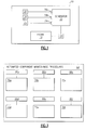
Figure 3 shows a schematic view of a memory portion of theFigure 2 generator test assembly. -
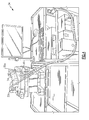
Figure 4 shows a perspective view of the generator and generator test assembly ofFigure 2 . -
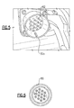
Figure 5 shows a close-up view of a connection interface of theFigure 4 generator. -
Figure 6 shows an end view of a cannon plug from theFigure 4 generator test assembly. - Referring to
Figure 1 , an example aircraft 10 includes adifferential gear assembly 14 rotatably coupling agas turbine engine 18 to agenerator 22. Thedifferential gear assembly 14 adjusts a rotational output from thegas turbine engine 18 so that thegenerator 22 is provided with a relatively consistent rotatable input, which allows thegenerator 22 to power a plurality ofaircraft components 26. Examples of theaircraft components 26 include lights and sensors onboard the aircraft 10. - The
generator 22 is an integrated drive generator in this example. Thegenerator 22 includes a plurality ofconnection interfaces 30a-30c that electrically couple thecomponents 26 to thegenerator 22. Theconnection interfaces 30a-30c are pin connectors in this example. Thecomponents 26 are decoupled from theconnection interfaces 30a-30c when thegenerator 22 is removed from the aircraft 10. When thegenerator 22 is installed within the aircraft 10, theconnection interfaces 30a-30c are used for communications between thegenerator 22 and a generator control unit in the aircraft 10, for example. - Referring now to
Figure 2 with continuing reference toFigure 1 , thegenerator 22 is periodically tested to determine the integrity of windings and coils within thegenerator 22, for example. Thegenerator 22 is also tested prior to installing thegenerator 22 in the aircraft 10 for the first time. During testing, thegenerator 22 is removed from the aircraft 10 and placed in a testing position, such as a bench in a testing lab. Example tests performed on thegenerator 22 include dielectric tests, resistance tests, insulation tests, etc. - In this example, a
generator test assembly 34 is used to test thegenerator 22. Thegenerator test assembly 34 includes atesting module 38 that is coupled to thegenerator 22 using a plurality of connectors 42. In this example, each of the connectors 42 engages one of theconnection interfaces 30a-30c. Notably, theconnection interfaces 30a-30c are the same as theconnection interfaces 30a-30c that electrically couplegenerator 22 to thecomponents 26 when thegenerator 22 is in an installed position within the aircraft 10. - The
testing module 38 is a type of computing device in this example. Apower supply 46 provides power to thetesting module 38. Theexample testing module 38 is linked to aprinter 50 and adisplay 54, and includes amemory portion 58 and aprocessor 62. - It should be noted that various types of computing devices can be used as the
testing module 38. In terms of hardware architecture, the computing device can include theprocessor 62,memory portion 58, and one or more input and/or output (I/O) device interface(s) that are communicatively coupled via a local interface. The local interface can include, for example but not limited to, one or more buses and/or other wired or wireless connections. The local interface may have additional elements, which are omitted for simplicity, such as controllers, buffers (caches), drivers, repeaters, and receivers to enable communications. Further, the local interface may include address, control, and/or data connections to enable appropriate communications among the aforementioned components. - The
processor 62 may be a hardware device for executing software, particularly software stored in thememory portion 58. Theprocessor 62 can be a custom made or commercially available processor, a central processing unit (CPU), an auxiliary processor among several processors associated with the computing device, a semiconductor based microprocessor (in the form of a microchip or chip set) or generally any device for executing software instructions. - The
memory portion 58 can include any one or combination of volatile memory elements (e.g., random access memory (RAM, such as DRAM, SRAM, SDRAM, VRAM, etc.)) and/or nonvolatile memory elements (e.g., ROM, hard drive, tape, CD-ROM, etc.). Moreover, thememory portion 58 may incorporate electronic, magnetic, optical, and/or other types of storage media. Note that thememory portion 58 can also have a distributed architecture, where various components are situated remotely from one another, but can be accessed by theprocessor 62. - The software in the
memory portion 58 may include one or more separate programs, each of which includes an ordered listing of executable instructions for implementing logical functions. A system component embodied as software may also be construed as a source program, executable program (object code), script, or any other entity comprising a set of instructions to be performed. When constructed as a source program, the program is translated via a compiler, assembler, interpreter, or the like, which may or may not be included within thememory portion 58. - The Input/Output devices that may be coupled to system I/O Interface(s) may include input devices, for example but not limited to, a keyboard, mouse, scanner, microphone, camera, proximity device, etc. Further, the Input/Output devices may also include output devices, for example but not limited to, the
printer 50, thedisplay 54, etc. Finally, the Input/Output devices may further include devices that communicate both as inputs and outputs, for instance but not limited to, a modulator/demodulator (modem; for accessing another device, system, or network), a radio frequency (RF) or other transceiver, a telephonic interface, a bridge, a router, etc. - When the computing device is in operation, the
processor 62 can be configured to execute software stored within thememory portion 58, to communicate data to and from thememory portion 58, and to generally control operations of the computing device pursuant to the software. Software in memory, in whole or in part, is read by theprocessor 62, perhaps buffered within theprocessor 62, and then executed. - Referring now to
Figure 3 with continuing reference toFigure 2 , thegenerator 22 has an associatedgenerator identifier 66a. In this example, thegenerator identifier 66a is a generator part number. Although the generator part number is used as the generator identifier in this example, other examples may include other types of generator identifiers. - Other types of generators include
other generator identifiers 66b-66f. As known, testing requirements for thegenerator 22 vary depending on the type of generator. - The
example memory portion 58 of thetesting module 38 stores a plurality of automatedcomponent maintenance procedures 68 that are derived from a component maintenance manual. Thecomponent maintenance procedures 68 include a plurality oftest requirements 70a-70e. Each of thetesting requirements 70a-70e is associated with one of thegenerator identifiers 66a-66f. Thecomponent maintenance procedures 68 includetesting requirements 70a-70f for thegenerator 22 and various other types of generators. - When testing the
generator 22, an operator inputs thegenerator identifier 66a into thetesting module 38 using theinput device 56. Theprocessor 62 then selects the appropriate testing requirement from thecomponent maintenance procedures 68 of thememory portion 58. Thetesting requirement 70a is the appropriate testing requirement in this example because thetesting requirement 70a is associated with thegenerator identifier 66a. - After determining the
testing requirement 70a, thetesting module 38 performs tests on thegenerator 22 according to thetesting requirements 70a. Example tests include dielectric tests, resistance tests, and insulation tests on thegenerator 22. Some of the tests require transmitting voltage to thegenerator 22 and then measuring relevant variables. Other tests, such as resistance tests, do not transmit voltage. In one specific test example, the resistance limit of a current transformer assembly within thegenerator 22 is tested. The current transformer assembly passes the test if the resistance limit of the current transformer assembly is 21.6 Ohms +/- 2 Ohms. - Referring to
Figure 4 , the examplegenerator test assembly 34 connects to anothergenerator 74 at the connection interfaces 30a-30c. As thegenerator 74 has been removed from the aircraft 10 (Figure 1 ), the connection interfaces 30a-30c are available for connection to thegenerator test assembly 34. - Referring now to
Figures 5 and 6 with continuing reference toFigure 4 , the connection interfaces 30a-30c each include multipleindividual pins 82 used to communicate power to and from thegenerator 74. - An
end 86 of one or more of the connectors 42 is a cannon plug in this example. The cannon plug includes multiple apertures each configured to receive a respective pin from theconnection interface 30a. Thetesting module 38 is able to communicate with eachpin 82 within theconnection interface 30a. Theend 86 communicates voltage through selected ones of thepins 82 to test thegenerator 74. The specific voltage levels are dictated by theappropriate testing requirements 70a-70f. - Features of the disclosed example include automatically testing and determining testing requirements for a generator. That is, a technician is not required to test individual pins within the generator or to look up specific testing requirements within a component maintenance manual.
- The preceding description is exemplary rather than limiting in nature. Variations and modifications to the disclosed examples may become apparent to those skilled in the art that do not necessarily depart from the scope of this disclosure. Thus, the scope of legal protection given to this disclosure can only be determined by studying the following claims.
Claims (15)
- A generator test assembly (34) comprising:a testing module (38) operative to test a generator (22;74) according to a test procedure; andat least one connector (42) configured to couple the generator to the testing module (38), wherein the generator (22;74) has a generator identifier (66a-66f) and the testing module is configured to select the test procedure from a plurality of potential test procedures based on the generator identifier.
- The generator test assembly (34) of claim 1, wherein the testing module (38) communicates a voltage to the generator (22;74) through the at least one connector (42).
- The generator test assembly (34) of claim 1 or 2, wherein the test comprises a dielectric test, a resistance test, an insulation test, or some combination of these.
- The generator test (34) assembly of claim 1, 2 or 3, wherein the at least one connector (42) comprises a cannon plug.
- The generator test assembly (34) of claim 1, 2, 3 or 4, wherein the generator identifier (66a-66f) comprises a generator part number.
- The generator test assembly (34) of any preceding claim, wherein the generator (22;74) is an integrated drive generator.
- The generator test assembly (34) of any preceding claim, wherein the generator (22;74) is configured to provide power to a plurality of aircraft components (26).
- The generator test assembly (34) any preceding claim, wherein the generator (22;74) includes at least one connection interface (30a-30c) that electrically couples the generator to an aircraft (10) when the generator is in an installed position and electrically couples the generator to the testing module (38) when the generator is in a testing position.
- A generator testing method, comprising:connecting a testing module (38) to a generator (22;74);providing the testing module with an identifier (66a-66f) associated with the generator (22;74);using the testing module (38) to select a test procedure based on the identifier; andusing the testing module (38) to test the generator (22;74) according to the test procedure.
- The generator testing method of claim 9, wherein the identifier (66a-66f) comprises a part number of the generator (22;74).
- The generator testing method of claim 9 or 10, wherein the test procedure is selected from a group of potential test procedures and preferably wherein the selecting comprises automatically selecting the test procedure from a plurality of component maintenance procedures.
- The generator testing method of claim 11, wherein the component maintenance procedures are electronically stored within a memory portion (58) of the testing module (38).
- The generator testing method of claim 9, 10, 11 or 12, wherein the testing comprises dielectric testing, resistance testing, insulation testing, or some combination of these.
- The generator testing method of any of claims 9 to 13, wherein the generator (22;74) is an integrated drive generator.
- The generator testing method of any of claims 9 to 14, including connecting using a cannon plug.
Applications Claiming Priority (1)
| Application Number | Priority Date | Filing Date | Title |
|---|---|---|---|
| US12/868,011 US8319517B2 (en) | 2010-08-25 | 2010-08-25 | Generator tester |
Publications (1)
| Publication Number | Publication Date |
|---|---|
| EP2423696A1 true EP2423696A1 (en) | 2012-02-29 |
Family
ID=44785255
Family Applications (1)
| Application Number | Title | Priority Date | Filing Date |
|---|---|---|---|
| EP11178647A Withdrawn EP2423696A1 (en) | 2010-08-25 | 2011-08-24 | Generator tester |
Country Status (4)
| Country | Link |
|---|---|
| US (1) | US8319517B2 (en) |
| EP (1) | EP2423696A1 (en) |
| CN (1) | CN102385038A (en) |
| SG (1) | SG178685A1 (en) |
Cited By (1)
| Publication number | Priority date | Publication date | Assignee | Title |
|---|---|---|---|---|
| CN116449202A (en) * | 2023-04-24 | 2023-07-18 | 杭州天盾电气设备有限公司 | Automatic program testing system for generator |
Families Citing this family (4)
| Publication number | Priority date | Publication date | Assignee | Title |
|---|---|---|---|---|
| US8855952B2 (en) * | 2011-01-05 | 2014-10-07 | Hamilton Sundstrand Corporation | Ram air turbine with flux regulated permanent magnet generator and testing method |
| US20160150327A1 (en) * | 2014-11-25 | 2016-05-26 | Knowles Electronics, Llc | Photosensitive Microphone |
| US10274542B1 (en) | 2018-11-27 | 2019-04-30 | Professional Generator Testers LLC | Electrical generator testing appliance |
| FR3114877B1 (en) * | 2020-10-06 | 2022-11-04 | Safran Aircraft Engines | DIAGNOSIS OF AN AIRCRAFT ENGINE COMPUTER |
Citations (3)
| Publication number | Priority date | Publication date | Assignee | Title |
|---|---|---|---|---|
| US5949247A (en) * | 1996-05-23 | 1999-09-07 | Fremont/Dynamics Coporation Of America | Method and apparatus for automatically testing and evaluating electric generator sets |
| EP1693661A1 (en) * | 2003-12-12 | 2006-08-23 | Hirata Corporation | Test equipment of engine motoring |
| US20070229018A1 (en) * | 2006-03-29 | 2007-10-04 | Mitchell Lawrence H | Brushless servo motor tester |
Family Cites Families (19)
| Publication number | Priority date | Publication date | Assignee | Title |
|---|---|---|---|---|
| US2700301A (en) | 1949-05-26 | 1955-01-25 | Weltronic Co | Engine testing apparatus |
| US4658213A (en) * | 1984-11-16 | 1987-04-14 | Finley Stanton M | Method and apparatus for testing direct current motors and generators, electromagnetic devices, and the like |
| US4799130A (en) | 1987-07-29 | 1989-01-17 | Acme Electric Corporation | Dielectric strength tester |
| JPH0776724B2 (en) | 1988-02-18 | 1995-08-16 | 富士重工業株式会社 | Vehicle diagnostic device |
| JP2522537B2 (en) | 1989-01-31 | 1996-08-07 | 株式会社テック | Facsimile diagnostic device |
| US5416416A (en) * | 1992-02-24 | 1995-05-16 | Bisher; Roger C. | Method and apparatus for testing an auxiliary power system |
| US5241277A (en) | 1992-02-28 | 1993-08-31 | United Technologies Corporation | Test system for automatic testing of insulation resistance, capacitance and attenuation of each contact pair in a filter pin connector |
| US5408412A (en) * | 1992-04-09 | 1995-04-18 | United Technologies Corporation | Engine fault diagnostic system |
| US5363317A (en) | 1992-10-29 | 1994-11-08 | United Technologies Corporation | Engine failure monitor for a multi-engine aircraft having partial engine failure and driveshaft failure detection |
| US5365166A (en) * | 1993-02-08 | 1994-11-15 | Westinghouse Electric Corporation | System and method for testing electrical generators |
| US6051987A (en) | 1997-04-18 | 2000-04-18 | Stokes; Robert | Apparatus and method for detection of residual magnetic fields in dynamoelectric machines |
| US5928022A (en) | 1997-10-28 | 1999-07-27 | Reliance Electric Industrial Company | Mechanically-assited clip device for use in testing electrical equipment |
| US6329933B1 (en) * | 1999-10-07 | 2001-12-11 | Stephen J. Mikesic | Portable emergency landing area lighting device for helicopters |
| US6651441B2 (en) * | 2002-01-22 | 2003-11-25 | Hamilton Sundstrand | Fluid flow system for a gas turbine engine |
| US6972554B1 (en) * | 2004-07-26 | 2005-12-06 | Honeywell International, Inc. | Universal aircraft generator electrical bench test apparatus |
| US7690573B2 (en) | 2006-07-27 | 2010-04-06 | Spx Corporation | Alternator and starter tester with bar code functionality and method |
| US7376876B2 (en) * | 2004-12-23 | 2008-05-20 | Honeywell International Inc. | Test program set generation tool |
| US7339776B1 (en) | 2006-12-12 | 2008-03-04 | Pratt & Whitney Rocketdyne, Inc. | Silicon carbide diode voltage limiter |
| CN101685138B (en) | 2008-09-26 | 2012-02-01 | 浙江师范大学 | A test method for the electrical performance of an alternator set |
-
2010
- 2010-08-25 US US12/868,011 patent/US8319517B2/en not_active Expired - Fee Related
-
2011
- 2011-08-16 SG SG2011058831A patent/SG178685A1/en unknown
- 2011-08-24 EP EP11178647A patent/EP2423696A1/en not_active Withdrawn
- 2011-08-25 CN CN201110246194XA patent/CN102385038A/en active Pending
Patent Citations (3)
| Publication number | Priority date | Publication date | Assignee | Title |
|---|---|---|---|---|
| US5949247A (en) * | 1996-05-23 | 1999-09-07 | Fremont/Dynamics Coporation Of America | Method and apparatus for automatically testing and evaluating electric generator sets |
| EP1693661A1 (en) * | 2003-12-12 | 2006-08-23 | Hirata Corporation | Test equipment of engine motoring |
| US20070229018A1 (en) * | 2006-03-29 | 2007-10-04 | Mitchell Lawrence H | Brushless servo motor tester |
Cited By (2)
| Publication number | Priority date | Publication date | Assignee | Title |
|---|---|---|---|---|
| CN116449202A (en) * | 2023-04-24 | 2023-07-18 | 杭州天盾电气设备有限公司 | Automatic program testing system for generator |
| CN116449202B (en) * | 2023-04-24 | 2024-03-29 | 杭州天盾电气设备有限公司 | A generator automatic program testing system |
Also Published As
| Publication number | Publication date |
|---|---|
| US8319517B2 (en) | 2012-11-27 |
| CN102385038A (en) | 2012-03-21 |
| SG178685A1 (en) | 2012-03-29 |
| US20120049886A1 (en) | 2012-03-01 |
Similar Documents
| Publication | Publication Date | Title |
|---|---|---|
| US8319517B2 (en) | Generator tester | |
| CN109507981B (en) | Vehicle testing method, apparatus and machine-readable storage medium | |
| EP2677618A2 (en) | Electrical power generation and distribution fault management system for a vehicle | |
| US20140081527A1 (en) | Alternator and Starter Tester with Increased Load and Cable Identification | |
| CN106546857A (en) | Electromagnetic interference test system and method for electric drive system of electric automobile | |
| CN103217264B (en) | A kind of accelerated reliability design test method being applicable to electronic product | |
| KR102554814B1 (en) | testing system and portable device for charging apparatus of electric vehicle | |
| TW201825913A (en) | Automated microtester array, computer implemented method and computer program product | |
| US10024923B2 (en) | Device and method for interfacing a vehicle-external testing device to a battery removed from a vehicle | |
| JPH0627178A (en) | Automatic test equipment for filter pin connector and method thereof | |
| EP1806591A2 (en) | High-voltage power supply control system and wireless controller and method therefor | |
| US20230408567A1 (en) | Diagnosis of an aircraft engine control unit | |
| US8577544B2 (en) | Method for examining a state of an electric circuit of a motor vehicle | |
| CN102650263B (en) | To the method and apparatus that wind turbine equipment is tested | |
| US12306239B2 (en) | Diagnosis of an aircraft engine control unit | |
| MXPA01007096A (en) | Device for testing cables that are provided with plug connectors. | |
| CN116653621B (en) | Relay drive control device, method, equipment, storage medium and vehicle | |
| EP3729576A2 (en) | Automatic multi-channel electronic test and measurement device | |
| KR102359560B1 (en) | Integrated automatizing and monitoring apparatus for EMC test | |
| JPS6333091B2 (en) | ||
| KR101663219B1 (en) | Apparatus and Method for checking electricity electronic circuit using interface signal simulation between in components | |
| KR20150062744A (en) | Method and Apparatus for Testing Vehicle and Engine | |
| US20250362358A1 (en) | Jumper wire, module and method for diagnosing the state of health of a plurality of electrical cables | |
| US20230266390A1 (en) | Test Abstraction Data Model | |
| JP2012255678A (en) | Testing apparatus and testing method for vehicular electronic module |
Legal Events
| Date | Code | Title | Description |
|---|---|---|---|
| AK | Designated contracting states |
Kind code of ref document: A1 Designated state(s): AL AT BE BG CH CY CZ DE DK EE ES FI FR GB GR HR HU IE IS IT LI LT LU LV MC MK MT NL NO PL PT RO RS SE SI SK SM TR |
|
| AX | Request for extension of the european patent |
Extension state: BA ME |
|
| PUAI | Public reference made under article 153(3) epc to a published international application that has entered the european phase |
Free format text: ORIGINAL CODE: 0009012 |
|
| 17P | Request for examination filed |
Effective date: 20120829 |
|
| 17Q | First examination report despatched |
Effective date: 20130410 |
|
| STAA | Information on the status of an ep patent application or granted ep patent |
Free format text: STATUS: THE APPLICATION IS DEEMED TO BE WITHDRAWN |
|
| 18D | Application deemed to be withdrawn |
Effective date: 20150303 |