EP2423624A2 - A cooling device - Google Patents
A cooling device Download PDFInfo
- Publication number
- EP2423624A2 EP2423624A2 EP11174512A EP11174512A EP2423624A2 EP 2423624 A2 EP2423624 A2 EP 2423624A2 EP 11174512 A EP11174512 A EP 11174512A EP 11174512 A EP11174512 A EP 11174512A EP 2423624 A2 EP2423624 A2 EP 2423624A2
- Authority
- EP
- European Patent Office
- Prior art keywords
- air
- chamber
- channel
- evaporator
- cooling device
- Prior art date
- Legal status (The legal status is an assumption and is not a legal conclusion. Google has not performed a legal analysis and makes no representation as to the accuracy of the status listed.)
- Withdrawn
Links
- 238000001816 cooling Methods 0.000 title claims abstract description 43
- 238000007664 blowing Methods 0.000 claims abstract description 7
- 125000004122 cyclic group Chemical group 0.000 description 11
- 239000003507 refrigerant Substances 0.000 description 8
- 230000007423 decrease Effects 0.000 description 1
- 230000003247 decreasing effect Effects 0.000 description 1
- 238000001704 evaporation Methods 0.000 description 1
Images



Classifications
-
- F—MECHANICAL ENGINEERING; LIGHTING; HEATING; WEAPONS; BLASTING
- F25—REFRIGERATION OR COOLING; COMBINED HEATING AND REFRIGERATION SYSTEMS; HEAT PUMP SYSTEMS; MANUFACTURE OR STORAGE OF ICE; LIQUEFACTION SOLIDIFICATION OF GASES
- F25D—REFRIGERATORS; COLD ROOMS; ICE-BOXES; COOLING OR FREEZING APPARATUS NOT OTHERWISE PROVIDED FOR
- F25D17/00—Arrangements for circulating cooling fluids; Arrangements for circulating gas, e.g. air, within refrigerated spaces
- F25D17/04—Arrangements for circulating cooling fluids; Arrangements for circulating gas, e.g. air, within refrigerated spaces for circulating air, e.g. by convection
- F25D17/06—Arrangements for circulating cooling fluids; Arrangements for circulating gas, e.g. air, within refrigerated spaces for circulating air, e.g. by convection by forced circulation
- F25D17/062—Arrangements for circulating cooling fluids; Arrangements for circulating gas, e.g. air, within refrigerated spaces for circulating air, e.g. by convection by forced circulation in household refrigerators
- F25D17/065—Arrangements for circulating cooling fluids; Arrangements for circulating gas, e.g. air, within refrigerated spaces for circulating air, e.g. by convection by forced circulation in household refrigerators with compartments at different temperatures
-
- F—MECHANICAL ENGINEERING; LIGHTING; HEATING; WEAPONS; BLASTING
- F25—REFRIGERATION OR COOLING; COMBINED HEATING AND REFRIGERATION SYSTEMS; HEAT PUMP SYSTEMS; MANUFACTURE OR STORAGE OF ICE; LIQUEFACTION SOLIDIFICATION OF GASES
- F25D—REFRIGERATORS; COLD ROOMS; ICE-BOXES; COOLING OR FREEZING APPARATUS NOT OTHERWISE PROVIDED FOR
- F25D2317/00—Details or arrangements for circulating cooling fluids; Details or arrangements for circulating gas, e.g. air, within refrigerated spaces, not provided for in other groups of this subclass
- F25D2317/06—Details or arrangements for circulating cooling fluids; Details or arrangements for circulating gas, e.g. air, within refrigerated spaces, not provided for in other groups of this subclass with forced air circulation
- F25D2317/065—Details or arrangements for circulating cooling fluids; Details or arrangements for circulating gas, e.g. air, within refrigerated spaces, not provided for in other groups of this subclass with forced air circulation characterised by the air return
- F25D2317/0654—Details or arrangements for circulating cooling fluids; Details or arrangements for circulating gas, e.g. air, within refrigerated spaces, not provided for in other groups of this subclass with forced air circulation characterised by the air return through the side
-
- F—MECHANICAL ENGINEERING; LIGHTING; HEATING; WEAPONS; BLASTING
- F25—REFRIGERATION OR COOLING; COMBINED HEATING AND REFRIGERATION SYSTEMS; HEAT PUMP SYSTEMS; MANUFACTURE OR STORAGE OF ICE; LIQUEFACTION SOLIDIFICATION OF GASES
- F25D—REFRIGERATORS; COLD ROOMS; ICE-BOXES; COOLING OR FREEZING APPARATUS NOT OTHERWISE PROVIDED FOR
- F25D2317/00—Details or arrangements for circulating cooling fluids; Details or arrangements for circulating gas, e.g. air, within refrigerated spaces, not provided for in other groups of this subclass
- F25D2317/06—Details or arrangements for circulating cooling fluids; Details or arrangements for circulating gas, e.g. air, within refrigerated spaces, not provided for in other groups of this subclass with forced air circulation
- F25D2317/066—Details or arrangements for circulating cooling fluids; Details or arrangements for circulating gas, e.g. air, within refrigerated spaces, not provided for in other groups of this subclass with forced air circulation characterised by the air supply
- F25D2317/0664—Details or arrangements for circulating cooling fluids; Details or arrangements for circulating gas, e.g. air, within refrigerated spaces, not provided for in other groups of this subclass with forced air circulation characterised by the air supply from the side
Definitions
- Present invention relates to air circulation between chamber and cooling element provided in cooling devices.
- Cooling cycle is generally carried out in cooling devices by units of compressor, condenser, capillary tube and cooling element (evaporator). Accordingly, in cooling system, refrigerant coming out of the compressor as hot is condensed after it releases its heat to external ambient and it gets cooled to some extent. Then, refrigerant, whose pressure decreases after it passes through the capillary tube, comes to evaporator. Herein, after the refrigerant vaporizes easily by both heat it takes from the chamber and low pressure it has, it gasifies. In evaporator, the refrigerant, which cools the chamber by taking heat from the chamber, comes to the compressor again, and then, cooling cycle known in state of art is completed and it is maintained in a cyclic way.
- cooling element evaporator
- Air circulation is created between the chamber and the evaporator in order to provide an efficient cooling and equal temperature distribution within the chamber provided in the cooling devices.
- One of these embodiments is disclosed in a patent application No. US3702544A in prior art.
- air cooled by means of the evaporator is guided to the air channels, whose one end corresponds with the evaporator and other end corresponds with the chamber. Air coming to the chamber by means of said channel firstly passes through the air passages provided between the chamber and the evaporator, secondly returns to the evaporator and finally, air circulation is created between the chamber and the evaporator.
- the present invention discloses a cooling device, in whose chamber cyclic air circulation is ensured.
- Said device comprises at least one chamber; at least one carrier element placed in this chamber; at least one compressor and one evaporator serving for cooling of said chamber; at least one air blowing unit canalizing air, which is cooled in evaporator, to the chamber by at least one air channel; at least one separator, which is provided in the channel and throughout the air channel, and then separates said channel into at least two portion as air forward channel and air return channel; at least one air inlet, which is provided in an upper portion formed by carrier element for the aim of ensuring air circulation in said portion and which is in connection with the air forward channel transferring cool air coming from the evaporator to the chamber; at least one air outlet, which is in connection with air return channel transferring hot air coming from the chamber to the evaporator; at least one air inlet, which is provided in lower portion formed by carrier element for the aim of ensuring air circulation in said portion and which is in connection with the air forward channel transferring cool
- Cool air coming from the evaporator gets in the chamber through the air inlets and by passing through air forward channel by means of air blowing device. Air, temperature of which increases due to heat of chamber, passes from the air outlets to the air return channel, finally returns to the evaporator. Thus, air circulation is created between the chamber and the evaporator. After cooled air gets in the chamber through air inlets and leaves the chamber through air outlets, cyclic air circulation is created. This ensures the chamber to be cooled in a more effective way and prevents air to accumulate in a certain point in the chamber. In addition, thanks to cyclic air circulation, equal temperature distribution is ensured within the chamber and stuff in the chamber is cooled in a more effective way.
- An aim of the invention is to develop a cooling device, in whose chamber cyclic air circulation is created.
- Another aim of the invention is to develop a cooling device, whose chamber is cooled in an efficient way.
- a further aim of the invention is to develop a cooling device, in whose chamber equal temperature distribution is obtained.
- Still a further aim of the invention is to develop a cooling device, which ensures foodstuff placed in the chamber to contact with air for much longer time.
- Yet a further aim of the invention is to prevent air to accumulate in a certain portion in the chamber provided in the cooling device.
- Cooling device Compressor (1) Condenser (2) Capillary tube (3) Cooling element (4) Chamber (5) Lower portion (5a) Upper portion (5b) Wall (6) Air channel (7) Air forward channel (7a) Air return channel (7b) Air inlet (8) Air outlet (9) Separator (10) Air blowing unit (11) Carrier element (12)
- Cooling system in cooling devices generally comprises at least one compressor (1), at least one condenser (2), at least one capillary tube (3) and at least one cooling element (evaporator) (4) shown in Figure 1 .
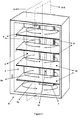
- An exemplary cooling device (S) comprising at least one chamber (5) and at least one cooling element (evaporator) (4) used for cooling said chamber (5) is illustrated in Figure 2 .
- Refrigerant coming out of the compressor (1) which is provided in said cooling device (S), as hot transfers its heat to external ambient while it passes through the condenser (2) and thus, it is condensed and cooled to some extent. Then, refrigerant, whose pressure is decreased after it passes through the capillary tube (3), comes to the evaporator (4).
- refrigerant which cools the chamber (5) due to heat it takes from the chamber (5), comes to compressor (1) again, and cooling cycle known in state of art is completed and it is maintained in a cyclic way.
- air flow between the evaporator (4) and the chamber (5) is carried out by means of at least one air channel (7) positioned on at least one wall (6). At least one side of this channel (7) corresponds with the evaporator (4) and by means of air inlet and outlet (8, 9) in the channel (7) air circulation is created between the chamber (5) and the chamber (4).
- Said air inlet and outlet (8, 9) are preferably provided on sides of the air channels (7), and thus cyclic air circulation is created within the chamber (5) after air coming from the air inlet (8) to chamber (5) leaves the chamber (5) by means of air outlet (9).
- Said air channel (7) is divided into at least two portions as air forward channel (7a) (shown in Figure 3 ) and air return channel (7b) (shown in Figure 4 ) by means of at least one separator (10) positioned throughout the channel (7) in the channel (7).
- Said separator (10) is in air-tight structure and air passage between two channels (7a, 7b) is prevented.
- Cool air leaving the evaporator (4) provided in the cooling device (S), whose A-A cross-section is illustrated in Figure 3 comes to the chamber (5) after it passes through the air forward channel (7a) by means of at least one air inlet (8), which connects said channel (7a) and the chamber (5).
- Air whose temperature increases by heat it takes from the chamber (5), comes to air return channel (7b) by means of at least one air outlet (9), which connects the chamber (5) and air return channel (7b) as shown in Figure 4 , and then it reaches the evaporator (4) by passing through in said channel (7b). Therefore, cyclic air circulation is created between inlet and outlet (8, 9) within the chamber (5) and also, the chamber (5) is cooled in a much efficient way.
- At least one air blowing unit (11) positioned output of the evaporator (4).
- Said air blowing unit (11) canalizes air cooled in evaporator (4) to air forward channel (7a).
- cyclic air circulation in the chamber (5) ensures equal temperature distribution in the chamber (5).
- foodstuff provided in the device (S) is ensured to contact with air for much longer time and air is prevented to accumulate in a certain portion of the chamber (5).
- inlet and outlet (8, 9) are positioned so as to they are present at lower portion (5a) and upper portion (5b) of at least one carrier element (12) (a rack may set example for the carrier element (12)) provided in the chamber (5).
- a rack may set example for the carrier element (12)
- cyclic air circulation within the portions (5a, 5b) formed by the carrier element (12) placed in the chamber (5) is maintained in separate inlet and outlet (5a, 5b) as independently from each other.
- foodstuff placed on the carrier element (12) is cooled more efficiently and thanks to cyclic air circulation, cool air reaches to food in equal amount.
- inlet and outlet (8, 9) are positioned between the carrier elements (12), equal temperature distribution is ensured in that portion between these elements.
Landscapes
- Engineering & Computer Science (AREA)
- Chemical & Material Sciences (AREA)
- Combustion & Propulsion (AREA)
- Physics & Mathematics (AREA)
- Mechanical Engineering (AREA)
- Thermal Sciences (AREA)
- General Engineering & Computer Science (AREA)
- Cold Air Circulating Systems And Constructional Details In Refrigerators (AREA)
- Devices That Are Associated With Refrigeration Equipment (AREA)
- Cooling Or The Like Of Electrical Apparatus (AREA)
Abstract
Description
- Present invention relates to air circulation between chamber and cooling element provided in cooling devices.
- Cooling cycle is generally carried out in cooling devices by units of compressor, condenser, capillary tube and cooling element (evaporator). Accordingly, in cooling system, refrigerant coming out of the compressor as hot is condensed after it releases its heat to external ambient and it gets cooled to some extent. Then, refrigerant, whose pressure decreases after it passes through the capillary tube, comes to evaporator. Herein, after the refrigerant vaporizes easily by both heat it takes from the chamber and low pressure it has, it gasifies. In evaporator, the refrigerant, which cools the chamber by taking heat from the chamber, comes to the compressor again, and then, cooling cycle known in state of art is completed and it is maintained in a cyclic way.
- Air circulation is created between the chamber and the evaporator in order to provide an efficient cooling and equal temperature distribution within the chamber provided in the cooling devices. There are various embodiments for said air circulation. One of these embodiments is disclosed in a patent application No.
US3702544A in prior art. In the device disclosed in this document, air cooled by means of the evaporator is guided to the air channels, whose one end corresponds with the evaporator and other end corresponds with the chamber. Air coming to the chamber by means of said channel firstly passes through the air passages provided between the chamber and the evaporator, secondly returns to the evaporator and finally, air circulation is created between the chamber and the evaporator. - In the cooling device disclosed in patent document No.
KR20030052103A - The present invention discloses a cooling device, in whose chamber cyclic air circulation is ensured. Said device comprises at least one chamber; at least one carrier element placed in this chamber; at least one compressor and one evaporator serving for cooling of said chamber; at least one air blowing unit canalizing air, which is cooled in evaporator, to the chamber by at least one air channel; at least one separator, which is provided in the channel and throughout the air channel, and then separates said channel into at least two portion as air forward channel and air return channel; at least one air inlet, which is provided in an upper portion formed by carrier element for the aim of ensuring air circulation in said portion and which is in connection with the air forward channel transferring cool air coming from the evaporator to the chamber; at least one air outlet, which is in connection with air return channel transferring hot air coming from the chamber to the evaporator; at least one air inlet, which is provided in lower portion formed by carrier element for the aim of ensuring air circulation in said portion and which is in connection with the air forward channel transferring cool air coming from the evaporator to the chamber; at least one air outlet, which is in connection with air return channel transferring hot air coming from the chamber to the evaporator.
- Cool air coming from the evaporator gets in the chamber through the air inlets and by passing through air forward channel by means of air blowing device. Air, temperature of which increases due to heat of chamber, passes from the air outlets to the air return channel, finally returns to the evaporator. Thus, air circulation is created between the chamber and the evaporator. After cooled air gets in the chamber through air inlets and leaves the chamber through air outlets, cyclic air circulation is created. This ensures the chamber to be cooled in a more effective way and prevents air to accumulate in a certain point in the chamber. In addition, thanks to cyclic air circulation, equal temperature distribution is ensured within the chamber and stuff in the chamber is cooled in a more effective way.
- An aim of the invention is to develop a cooling device, in whose chamber cyclic air circulation is created.
- Another aim of the invention is to develop a cooling device, whose chamber is cooled in an efficient way.
- A further aim of the invention is to develop a cooling device, in whose chamber equal temperature distribution is obtained.
- Still a further aim of the invention is to develop a cooling device, which ensures foodstuff placed in the chamber to contact with air for much longer time.
- Yet a further aim of the invention is to prevent air to accumulate in a certain portion in the chamber provided in the cooling device.
- An exemplary cooling device of the invention and cooling cycle elements therein are illustrated in annexed figures, wherein;
-
Figure 1 is view of the cooling cycle elements and cooling cycle. -
Figure 2 is perspective view of the cooling device. -
Figure 3 is a view of A-A cross-section of the cooling device illustrated inFigure 2 . -
Figure 4 is a view of B-B cross-section of the cooling device illustrated inFigure 2 . - All the parts illustrated in figures are individually assigned a reference numeral and the corresponding terms of these numbers are listed below:
Cooling device (S) Compressor (1) Condenser (2) Capillary tube (3) Cooling element (4) Chamber (5) Lower portion (5a) Upper portion (5b) Wall (6) Air channel (7) Air forward channel (7a) Air return channel (7b) Air inlet (8) Air outlet (9) Separator (10) Air blowing unit (11) Carrier element (12) - Cooling system in cooling devices (shown in
figures 2-4 ) generally comprises at least one compressor (1), at least one condenser (2), at least one capillary tube (3) and at least one cooling element (evaporator) (4) shown inFigure 1 . An exemplary cooling device (S) comprising at least one chamber (5) and at least one cooling element (evaporator) (4) used for cooling said chamber (5) is illustrated inFigure 2 . Refrigerant coming out of the compressor (1), which is provided in said cooling device (S), as hot transfers its heat to external ambient while it passes through the condenser (2) and thus, it is condensed and cooled to some extent. Then, refrigerant, whose pressure is decreased after it passes through the capillary tube (3), comes to the evaporator (4). Refrigerant gasifies by evaporating easily due to both heat it takes from the chamber (5) and low pressure it has. In the evaporator (4), refrigerant, which cools the chamber (5) due to heat it takes from the chamber (5), comes to compressor (1) again, and cooling cycle known in state of art is completed and it is maintained in a cyclic way. - In the device (S) of the invention illustrated in
Figure 2 , air flow between the evaporator (4) and the chamber (5) is carried out by means of at least one air channel (7) positioned on at least one wall (6). At least one side of this channel (7) corresponds with the evaporator (4) and by means of air inlet and outlet (8, 9) in the channel (7) air circulation is created between the chamber (5) and the chamber (4). Said air inlet and outlet (8, 9) are preferably provided on sides of the air channels (7), and thus cyclic air circulation is created within the chamber (5) after air coming from the air inlet (8) to chamber (5) leaves the chamber (5) by means of air outlet (9). - Said air channel (7) is divided into at least two portions as air forward channel (7a) (shown in
Figure 3 ) and air return channel (7b) (shown inFigure 4 ) by means of at least one separator (10) positioned throughout the channel (7) in the channel (7). Said separator (10) is in air-tight structure and air passage between two channels (7a, 7b) is prevented. Cool air leaving the evaporator (4) provided in the cooling device (S), whose A-A cross-section is illustrated inFigure 3 , comes to the chamber (5) after it passes through the air forward channel (7a) by means of at least one air inlet (8), which connects said channel (7a) and the chamber (5). Air, whose temperature increases by heat it takes from the chamber (5), comes to air return channel (7b) by means of at least one air outlet (9), which connects the chamber (5) and air return channel (7b) as shown inFigure 4 , and then it reaches the evaporator (4) by passing through in said channel (7b). Therefore, cyclic air circulation is created between inlet and outlet (8, 9) within the chamber (5) and also, the chamber (5) is cooled in a much efficient way. - In an exemplary embodiment of the invention illustrated in figures, there is provided at least one air blowing unit (11) positioned output of the evaporator (4). Said air blowing unit (11) canalizes air cooled in evaporator (4) to air forward channel (7a).
- In the embodiment developed by said invention, cyclic air circulation in the chamber (5) ensures equal temperature distribution in the chamber (5). In addition to this, thanks to this system, foodstuff provided in the device (S) is ensured to contact with air for much longer time and air is prevented to accumulate in a certain portion of the chamber (5).
- In an exemplary embodiment of the invention, inlet and outlet (8, 9) are positioned so as to they are present at lower portion (5a) and upper portion (5b) of at least one carrier element (12) (a rack may set example for the carrier element (12)) provided in the chamber (5). In other words, cyclic air circulation within the portions (5a, 5b) formed by the carrier element (12) placed in the chamber (5) is maintained in separate inlet and outlet (5a, 5b) as independently from each other. Thus, foodstuff placed on the carrier element (12) is cooled more efficiently and thanks to cyclic air circulation, cool air reaches to food in equal amount. Moreover, since inlet and outlet (8, 9) are positioned between the carrier elements (12), equal temperature distribution is ensured in that portion between these elements.
Claims (5)
- A cooling device (S) comprising at least one chamber (5); at least one carrier element (12) placed in said chamber (5); at least one compressor (1) and at least one evaporator (4) used for cooling said chamber (5); at least one air blowing unit (11) canalizing air cooled in the evaporator (4) to the chamber (5) by means of at least one air channel (7) characterized in that it comprises- at least one separator (10), which is provided in the channel (7) and positioned throughout the channel (7), and then separates said channel (7) into at least two portion as air forward channel (7a) and air return channel (7b);- at least one air inlet (8), which is provided in upper portion (5b) formed by carrier element (12) for the aim of ensuring air circulation in said portion (5b) and which is in connection with the air forward channel (7a) transferring cool air coming from the evaporator (4) to the chamber (5); at least one air outlet (9), which is in connection with air return channel (7b) transferring hot air coming from the chamber (5) to the evaporator (4);- at least one air inlet (8), which is provided in lower portion (5a) formed by carrier element (12) for the aim of ensuring air circulation in said portion (5a) and which is in connection with the air forward channel (7a) transferring cool air coming from the evaporator (4) to the chamber (5); at least one air outlet (9), which is in connection with air return channel (7b) transferring hot air coming from the chamber (5) to the evaporator (4).
- A cooling device (S) according to Claim 1 characterized in that, the air channel (7) is positioned on at least one wall (6) of the device (S).
- A cooling device (S) according to Claim 1 characterized in that, at least one side of said air channel (7) faces the evaporator (4).
- A cooling device (S) according to Claim 1 characterized in that, said separator (10) has air-tight structure.
- A cooling device (S) according to Claim 1 characterized in that, said inlet and outlet (8, 9) are provided on sides of air channel (7).
Applications Claiming Priority (1)
| Application Number | Priority Date | Filing Date | Title |
|---|---|---|---|
| TR2010/07211A TR201007211A2 (en) | 2010-08-27 | 2010-08-27 | A cooling device. |
Publications (2)
| Publication Number | Publication Date |
|---|---|
| EP2423624A2 true EP2423624A2 (en) | 2012-02-29 |
| EP2423624A3 EP2423624A3 (en) | 2013-12-11 |
Family
ID=44947416
Family Applications (1)
| Application Number | Title | Priority Date | Filing Date |
|---|---|---|---|
| EP11174512.1A Withdrawn EP2423624A3 (en) | 2010-08-27 | 2011-07-19 | A cooling device |
Country Status (2)
| Country | Link |
|---|---|
| EP (1) | EP2423624A3 (en) |
| TR (1) | TR201007211A2 (en) |
Cited By (1)
| Publication number | Priority date | Publication date | Assignee | Title |
|---|---|---|---|---|
| WO2020228414A1 (en) * | 2019-05-10 | 2020-11-19 | 青岛海尔电冰箱有限公司 | Refrigerating and freezing device |
Citations (2)
| Publication number | Priority date | Publication date | Assignee | Title |
|---|---|---|---|---|
| US3702544A (en) | 1970-09-25 | 1972-11-14 | Unitec Ind Inc | Refrigerator |
| KR20030052103A (en) | 2001-12-20 | 2003-06-26 | 주식회사 엘지이아이 | Refrigerator having structure for circulation of cooling air |
Family Cites Families (5)
| Publication number | Priority date | Publication date | Assignee | Title |
|---|---|---|---|---|
| US3982584A (en) * | 1975-04-23 | 1976-09-28 | Owens-Illinois, Inc. | Gas temperature and flow control system |
| KR100504048B1 (en) * | 1998-09-02 | 2005-09-26 | 삼성전자주식회사 | Refrigerator |
| DE202005009581U1 (en) * | 2005-06-18 | 2005-10-13 | Geiger, Johann | Cooling modules for container with swing door may be installed in one sidewall or in the roof and have heat rejection fins on outside and circulating fans on inside of container |
| EP1873468A2 (en) * | 2006-06-26 | 2008-01-02 | Dometic Sweden AB | Refrigerator cabinet |
| BRPI0705750A2 (en) * | 2007-08-17 | 2009-04-14 | Whirlpool Sa | cooling module, cooling system, cooling tower and distribution duct |
-
2010
- 2010-08-27 TR TR2010/07211A patent/TR201007211A2/en unknown
-
2011
- 2011-07-19 EP EP11174512.1A patent/EP2423624A3/en not_active Withdrawn
Patent Citations (2)
| Publication number | Priority date | Publication date | Assignee | Title |
|---|---|---|---|---|
| US3702544A (en) | 1970-09-25 | 1972-11-14 | Unitec Ind Inc | Refrigerator |
| KR20030052103A (en) | 2001-12-20 | 2003-06-26 | 주식회사 엘지이아이 | Refrigerator having structure for circulation of cooling air |
Cited By (1)
| Publication number | Priority date | Publication date | Assignee | Title |
|---|---|---|---|---|
| WO2020228414A1 (en) * | 2019-05-10 | 2020-11-19 | 青岛海尔电冰箱有限公司 | Refrigerating and freezing device |
Also Published As
| Publication number | Publication date |
|---|---|
| TR201007211A2 (en) | 2010-12-21 |
| EP2423624A3 (en) | 2013-12-11 |
Similar Documents
| Publication | Publication Date | Title |
|---|---|---|
| KR100409265B1 (en) | Regenerative evaporative cooler | |
| KR101443873B1 (en) | Auxiliary cooling system | |
| US20140260364A1 (en) | Specialty cooling features using extruded evaporator | |
| EP3396279A1 (en) | Refrigerator | |
| JP6679573B2 (en) | Thermosiphon with integrated components | |
| US20080110604A1 (en) | Heat exchanger | |
| GB2578023A (en) | Refrigeration cycle device | |
| US7644983B2 (en) | Evaporatively pre-cooled seat assembly | |
| CN106196333A (en) | Air conditioner | |
| KR100261476B1 (en) | Evaporator of separating type airconditioner | |
| US20160363378A1 (en) | Heat exchanger and a method for forming a heat exchanger | |
| JP2016003831A (en) | refrigerator | |
| EP2423624A2 (en) | A cooling device | |
| EP2860477B1 (en) | A cooling unit for a climatized cabinet | |
| US9625203B2 (en) | Moisture control system for an appliance and method for controlling moisture within an appliance | |
| CN101965141A (en) | Device for generating an air wall in an upright refrigerated cabinet | |
| US11277939B2 (en) | Evaporator and manufacturing method | |
| US7334431B2 (en) | Evaporator and heat exchanger with external loop, as well as heat pump system and air conditioning system comprising said evaporator or heat exchanger | |
| WO2016173790A1 (en) | Cooling device comprising a condenser used in two independent refrigeration cycles | |
| US20070125110A1 (en) | Device for transfer of heat | |
| US8910488B2 (en) | Display case including heat exchanger for reducing relative humidity | |
| EP2426441A2 (en) | A cooling device | |
| EP3112791B1 (en) | Laminated header, heat exchanger, and air conditioning device | |
| EP1853139B1 (en) | Refridgerated display chest | |
| JP5278025B2 (en) | vending machine |
Legal Events
| Date | Code | Title | Description |
|---|---|---|---|
| AK | Designated contracting states |
Kind code of ref document: A2 Designated state(s): AL AT BE BG CH CY CZ DE DK EE ES FI FR GB GR HR HU IE IS IT LI LT LU LV MC MK MT NL NO PL PT RO RS SE SI SK SM TR |
|
| AX | Request for extension of the european patent |
Extension state: BA ME |
|
| PUAI | Public reference made under article 153(3) epc to a published international application that has entered the european phase |
Free format text: ORIGINAL CODE: 0009012 |
|
| PUAL | Search report despatched |
Free format text: ORIGINAL CODE: 0009013 |
|
| AK | Designated contracting states |
Kind code of ref document: A3 Designated state(s): AL AT BE BG CH CY CZ DE DK EE ES FI FR GB GR HR HU IE IS IT LI LT LU LV MC MK MT NL NO PL PT RO RS SE SI SK SM TR |
|
| AX | Request for extension of the european patent |
Extension state: BA ME |
|
| RIC1 | Information provided on ipc code assigned before grant |
Ipc: F25D 17/06 20060101AFI20131105BHEP |
|
| 17P | Request for examination filed |
Effective date: 20140220 |
|
| STAA | Information on the status of an ep patent application or granted ep patent |
Free format text: STATUS: THE APPLICATION IS DEEMED TO BE WITHDRAWN |
|
| 18D | Application deemed to be withdrawn |
Effective date: 20160202 |