EP2423468A2 - Combined cycle power plant - Google Patents
Combined cycle power plant Download PDFInfo
- Publication number
- EP2423468A2 EP2423468A2 EP09174687A EP09174687A EP2423468A2 EP 2423468 A2 EP2423468 A2 EP 2423468A2 EP 09174687 A EP09174687 A EP 09174687A EP 09174687 A EP09174687 A EP 09174687A EP 2423468 A2 EP2423468 A2 EP 2423468A2
- Authority
- EP
- European Patent Office
- Prior art keywords
- heat transfer
- metal foam
- transfer tubes
- steam
- gas turbine
- Prior art date
- Legal status (The legal status is an assumption and is not a legal conclusion. Google has not performed a legal analysis and makes no representation as to the accuracy of the status listed.)
- Withdrawn
Links
- XLYOFNOQVPJJNP-UHFFFAOYSA-N water Substances O XLYOFNOQVPJJNP-UHFFFAOYSA-N 0.000 claims abstract description 20
- 238000000034 method Methods 0.000 claims abstract description 16
- 238000011084 recovery Methods 0.000 claims abstract description 15
- 230000001413 cellular effect Effects 0.000 claims abstract description 9
- 239000000463 material Substances 0.000 claims abstract description 9
- 238000004891 communication Methods 0.000 claims abstract description 7
- 239000012530 fluid Substances 0.000 claims abstract description 6
- 239000006262 metallic foam Substances 0.000 claims description 41
- 238000002485 combustion reaction Methods 0.000 claims 1
- 230000005611 electricity Effects 0.000 abstract description 3
- 239000008236 heating water Substances 0.000 abstract 1
- 230000003111 delayed effect Effects 0.000 description 2
- 238000000926 separation method Methods 0.000 description 2
- 238000005219 brazing Methods 0.000 description 1
- 238000009792 diffusion process Methods 0.000 description 1
- 230000008030 elimination Effects 0.000 description 1
- 238000003379 elimination reaction Methods 0.000 description 1
- 239000002184 metal Substances 0.000 description 1
- 229910052751 metal Inorganic materials 0.000 description 1
- 150000002739 metals Chemical class 0.000 description 1
- 239000000843 powder Substances 0.000 description 1
- 239000007787 solid Substances 0.000 description 1
- 238000003466 welding Methods 0.000 description 1
Images


Classifications
-
- F—MECHANICAL ENGINEERING; LIGHTING; HEATING; WEAPONS; BLASTING
- F02—COMBUSTION ENGINES; HOT-GAS OR COMBUSTION-PRODUCT ENGINE PLANTS
- F02C—GAS-TURBINE PLANTS; AIR INTAKES FOR JET-PROPULSION PLANTS; CONTROLLING FUEL SUPPLY IN AIR-BREATHING JET-PROPULSION PLANTS
- F02C6/00—Plural gas-turbine plants; Combinations of gas-turbine plants with other apparatus; Adaptations of gas-turbine plants for special use
- F02C6/18—Plural gas-turbine plants; Combinations of gas-turbine plants with other apparatus; Adaptations of gas-turbine plants for special use using the waste heat of gas-turbine plants outside the plants themselves, e.g. gas-turbine power heat plants
-
- F—MECHANICAL ENGINEERING; LIGHTING; HEATING; WEAPONS; BLASTING
- F01—MACHINES OR ENGINES IN GENERAL; ENGINE PLANTS IN GENERAL; STEAM ENGINES
- F01K—STEAM ENGINE PLANTS; STEAM ACCUMULATORS; ENGINE PLANTS NOT OTHERWISE PROVIDED FOR; ENGINES USING SPECIAL WORKING FLUIDS OR CYCLES
- F01K23/00—Plants characterised by more than one engine delivering power external to the plant, the engines being driven by different fluids
- F01K23/02—Plants characterised by more than one engine delivering power external to the plant, the engines being driven by different fluids the engine cycles being thermally coupled
- F01K23/06—Plants characterised by more than one engine delivering power external to the plant, the engines being driven by different fluids the engine cycles being thermally coupled combustion heat from one cycle heating the fluid in another cycle
- F01K23/10—Plants characterised by more than one engine delivering power external to the plant, the engines being driven by different fluids the engine cycles being thermally coupled combustion heat from one cycle heating the fluid in another cycle with exhaust fluid of one cycle heating the fluid in another cycle
-
- F—MECHANICAL ENGINEERING; LIGHTING; HEATING; WEAPONS; BLASTING
- F28—HEAT EXCHANGE IN GENERAL
- F28D—HEAT-EXCHANGE APPARATUS, NOT PROVIDED FOR IN ANOTHER SUBCLASS, IN WHICH THE HEAT-EXCHANGE MEDIA DO NOT COME INTO DIRECT CONTACT
- F28D7/00—Heat-exchange apparatus having stationary tubular conduit assemblies for both heat-exchange media, the media being in contact with different sides of a conduit wall
- F28D7/16—Heat-exchange apparatus having stationary tubular conduit assemblies for both heat-exchange media, the media being in contact with different sides of a conduit wall the conduits being arranged in parallel spaced relation
- F28D7/1615—Heat-exchange apparatus having stationary tubular conduit assemblies for both heat-exchange media, the media being in contact with different sides of a conduit wall the conduits being arranged in parallel spaced relation the conduits being inside a casing and extending at an angle to the longitudinal axis of the casing; the conduits crossing the conduit for the other heat exchange medium
-
- F—MECHANICAL ENGINEERING; LIGHTING; HEATING; WEAPONS; BLASTING
- F28—HEAT EXCHANGE IN GENERAL
- F28F—DETAILS OF HEAT-EXCHANGE AND HEAT-TRANSFER APPARATUS, OF GENERAL APPLICATION
- F28F13/00—Arrangements for modifying heat-transfer, e.g. increasing, decreasing
- F28F13/003—Arrangements for modifying heat-transfer, e.g. increasing, decreasing by using permeable mass, perforated or porous materials
-
- F—MECHANICAL ENGINEERING; LIGHTING; HEATING; WEAPONS; BLASTING
- F05—INDEXING SCHEMES RELATING TO ENGINES OR PUMPS IN VARIOUS SUBCLASSES OF CLASSES F01-F04
- F05D—INDEXING SCHEME FOR ASPECTS RELATING TO NON-POSITIVE-DISPLACEMENT MACHINES OR ENGINES, GAS-TURBINES OR JET-PROPULSION PLANTS
- F05D2220/00—Application
- F05D2220/30—Application in turbines
- F05D2220/31—Application in turbines in steam turbines
-
- Y—GENERAL TAGGING OF NEW TECHNOLOGICAL DEVELOPMENTS; GENERAL TAGGING OF CROSS-SECTIONAL TECHNOLOGIES SPANNING OVER SEVERAL SECTIONS OF THE IPC; TECHNICAL SUBJECTS COVERED BY FORMER USPC CROSS-REFERENCE ART COLLECTIONS [XRACs] AND DIGESTS
- Y02—TECHNOLOGIES OR APPLICATIONS FOR MITIGATION OR ADAPTATION AGAINST CLIMATE CHANGE
- Y02E—REDUCTION OF GREENHOUSE GAS [GHG] EMISSIONS, RELATED TO ENERGY GENERATION, TRANSMISSION OR DISTRIBUTION
- Y02E20/00—Combustion technologies with mitigation potential
- Y02E20/14—Combined heat and power generation [CHP]
-
- Y—GENERAL TAGGING OF NEW TECHNOLOGICAL DEVELOPMENTS; GENERAL TAGGING OF CROSS-SECTIONAL TECHNOLOGIES SPANNING OVER SEVERAL SECTIONS OF THE IPC; TECHNICAL SUBJECTS COVERED BY FORMER USPC CROSS-REFERENCE ART COLLECTIONS [XRACs] AND DIGESTS
- Y02—TECHNOLOGIES OR APPLICATIONS FOR MITIGATION OR ADAPTATION AGAINST CLIMATE CHANGE
- Y02E—REDUCTION OF GREENHOUSE GAS [GHG] EMISSIONS, RELATED TO ENERGY GENERATION, TRANSMISSION OR DISTRIBUTION
- Y02E20/00—Combustion technologies with mitigation potential
- Y02E20/16—Combined cycle power plant [CCPP], or combined cycle gas turbine [CCGT]
Definitions
- the subject matter disclosed herein relates to a combined cycle power plant and, more particularly, to the heat recovery boiler with enhanced heat transfer surface area for improved combined cycle performance and economics.
- the subject matter applies to a single shaft, combined cycle power plant, a multi-shaft, combined cycle power plant and a cogeneration power plant.
- the subject matter may be applicable to natural circulation, forced circulation and once through heat recovery boilers configured with horizontal and/or vertical heat transfer tubes with gas turbine exhaust flow in either a horizontal and/or vertical direction.
- the heat recovery boiler tube arrangement may be in-line or staggered and the heat recovery boiler may be unfired or supplementary fired.
- Combined cycle power plants utilize at least one gas turbine, at least one steam turbine and heat recovery boilers in combination to produce electricity and/or to process steam.
- the power plant is arranged such that the gas turbine is thermally connected to the steam turbine and/or process steam system through a heat recovery boiler such as a Heat Recovery Steam Generator ("HRSG").
- HRSG Heat Recovery Steam Generator
- the HRSG is essentially a large duct with water/steam filled heat exchanger tube bundles interposed therein. Feed water enters an economizer and circulates through the tube bundles such that the water is converted to steam as the gas turbine exhaust gas passes through the duct and over the tube bundles.
- the combined cycle power plant derives its thermal efficiency from the use of the heat rejected from the gas turbine as a supply of energy for the steam bottoming cycle (steam turbine and/or process steam).
- the performance and economics of the HRSG is directly related to the efficiency of heat transfer between the gas turbine exhaust gas (hot side) and the water/steam in the tube bundles (cold side).
- HRSGs typically utilize finned type tubes (solid and serrated) to enhance the rate of heat transfer from the gas turbine exhaust gas to the water/steam in the tube bundles however, overall heat transfer is limited by the heat transfer surface area which is located within the duct of the HRSG and the need to maintain reasonable flow characteristics and pressure drop of the gas turbine exhaust gas.
- a combined cycle power plant includes a gas turbine and a steam turbine that are thermally connected by a heat recovery steam generator.
- the heat recovery steam generator includes a duct for receiving and confining gas turbine exhaust gas from the gas turbine.
- Heat transfer tubes are disposed within the duct and have exterior surfaces in fluid communication with the gas turbine exhaust gas and interior surfaces in circulatory fluid communication with water and steam.
- a cellular material is attached to the exterior surfaces of the heat transfer tubes and operates to enhance heat transfer from the gas turbine exhaust gas to the water and/or steam.
- a method of configuring a combined cycle power plant heat recovery steam generator may comprise the steps of configuring a duct to receive and confine gas turbine exhaust gas. Disposing a series of heat transfer tubes in the duct that are configured to receive water and/or steam and applying a cellular material to the exterior surfaces of the heat transfer tubes.
- FIG. 1 shows an exemplary embodiment of a single shaft, combined cycle power plant 10.
- the combined cycle power plant includes a gas turbine system 12, a steam turbine system 14 and a generator 16 that is driven by the gas and steam turbines to generate electricity.
- the gas turbine system includes, in serial flow communication, a multistage axial compressor 18, a combustor 20, and a multi-stage turbine 22.
- the gas turbine system 12 and the steam turbine system 14 are thermally connected through HRSG 24.
- the HRSG 24 is a heat exchanger configured to include a duct 28 for receipt and confinement of gas turbine exhaust gas 30 exiting the multi-stage turbine 22.
- Bundles of heat transfer tubes 32 are disposed within the duct 28 of the HRSG 24 and are adapted to receive feed water 34 (condensate from steam turbine condenser 15) that is circulated through the tubes by the feed water pump 36. As the feed water 34 passes through the heat transfer tubes 32, heat from the gas turbine exhaust gas 30 passing through the HRSG duct 28 is transferred to the water, creating steam. The steam is supplied to, and drives, the steam turbine 14, through the main steam piping 38. In addition, the steam from the HRSG may also be supplied to a process steam system (not shown).
- the exterior of the heat transfer tubes 32 represent the "hot side” surface area while the interior, or wet side, of the heat transfer tubes represent the "cold side” surface area.
- Enhanced transfer of heat between the hot and cold side surface areas of the HRSG will operate to increase the performance and economics of the combined cycle power plant 10.
- a portion of the heat transfer tubes 32 is shown.
- a cellular material, such as metal foam extended surface 40 surrounds the heat transfer tubes 32.
- the metal foam extended surface is comprised of a relatively new class of materials having low density, high surface area and good strength.
- the metal foam extended surface may be formed from various powder metals and, with varying porosity.
- Controlling the material properties and configuration of the metal foam extended surface 40 is an important aspect of the invention in that the pressure drop of the gas turbine exhaust gas 30 passing through the HRSG duct 28 is a consideration in the design of the HRSG. High pressure drops across the bundles of heat transfer tubes 32 will reduce the power output of the gas turbine system 12. As indicated in the plot shown, studies show that metal foam with appropriate porosity and density, which relates directly to pressure drop, can achieve lower pressure drop. Additionally, due to the unique structural characteristics of the metal foam, it has sound and vibration absorptive characteristics that are useful in relieving acoustical and vibration issues in the HRSG 24 and may allow for reduction or elimination of costly silencers and acoustic baffles used to modify the acoustic characteristics of the HRSG.
- the metal foam extended surface 40 is defined by a series of metal foam segments 42 having a relatively discshaped configuration with an axially extending opening 45 and interior and exterior surfaces 44 and 46, respectively.
- the axially extending openings have a diameter "d" configured to receive a heat transfer tube 32 therein.
- the diameter "d" closely matches the outside diameter of the heat transfer tubes 32 such that when a metal foam segment 42 is installed onto a tube, surface area contact between the interior surface 44 of the segment and the outer surface 52 of the heat transfer tube 32 is high.
- the metal foam segments 42 are attached using appropriate metallurgical joining techniques such as brazing, welding, diffusion bonding or other suitable methods.
- each metal foam segment 42 of the metal foam extended surface 40 operates to increase the rate of heat transfer from the gas turbine exhaust gas passing through the HRSG duct 28 to the water/steam 35 circulating in the heat transfer tubes 32.
- exhaust gas backpressure experienced by the gas turbine can be maintained at acceptable levels.
- each metal foam segment 42 has an axial height "h” and is preferably spaced from adjacent segments by an axial distance "g".
- Backpressure within the HRSG duct 28 has been found to fall within a desirable range when the ratio of the metal foam segment height "h" to the segment spacing "g" is within a range of greater than 0 to about 50 (i.e. 0 ⁇ h/g ⁇ 50).
- heat transfer reaches satisfactory levels when the ratio of the metal foam segment outer diameter "D" to the segment inner diameter "d” is within a range of about 1.2 to about 10 (i.e. 1.2 ⁇ D / d ⁇ 10).
- the gas turbine exhaust gas flowing through the HRSG duct 28 will produce a smaller wake area 54, as compared with a conventionally finned tube, due to delayed flow separation.
- the smaller wake area 54 is a result of a turbulent boundary layer directly adjacent the exterior surface 46 and it operates to reduce backpressure through the HRSG 24.
- metal foam segments 42 have been generally described as cylindrical in configuration, the present invention contemplates segments in a variety of shapes and sizes. It is contemplated that the configuration and spacing of the metal foam segments 42 will be selected to efficiently transfer heat to the heat transfer tubes 32 while lowering the gas turbine exhaust backpressure within the duct 28 of the HRSG 24.
- the combined cycle power plant 10 has been described having a single shaft configuration with a single gas turbine, steam turbine and generator, any number of application driven variations are also contemplated. For example it is contemplated that the invention has similar applicability to multiple shaft, combined cycle power plants and cogeneration power plants.
- the invention may be used in natural circulation, forced circulation and once through HRSGs configured with horizontal and/or vertical heat transfer tubes with gas turbine exhaust gas flow in horizontal and/or vertical directions.
- the HRSG tube arrangement may be either in-line or staggered and the HRSG may be either unfired or supplementary fired.
Landscapes
- Engineering & Computer Science (AREA)
- Chemical & Material Sciences (AREA)
- Mechanical Engineering (AREA)
- General Engineering & Computer Science (AREA)
- Combustion & Propulsion (AREA)
- Physics & Mathematics (AREA)
- Thermal Sciences (AREA)
- Dispersion Chemistry (AREA)
- Engine Equipment That Uses Special Cycles (AREA)
Abstract
A combined cycle power plant (10) includes at least one gas turbine (12), at least one steam turbine (14) and a heat recovery boiler (24) in combination to produce electricity and/or process steam. The heat recovery boiler (24) has a duct (28) for receiving and confining gas turbine exhaust gas (30) from the gas turbine (12). Heat transfer tubes (32) for heating water and steam (35) for use in the bottoming steam cycle (steam turbine and/or process steam) are disposed within the heat recovery boiler (24) and have exterior surfaces in fluid communication with the gas turbine exhaust gas (30) and interior surfaces in circulatory fluid communication with water and/or steam (35). A cellular material (40) is attached to the exterior surfaces of the heat transfer tubes (32) and operates to enhance heat transfer from the gas turbine exhaust gas (30) to the water and/or steam (35).
Description
- The subject matter disclosed herein relates to a combined cycle power plant and, more particularly, to the heat recovery boiler with enhanced heat transfer surface area for improved combined cycle performance and economics. The subject matter applies to a single shaft, combined cycle power plant, a multi-shaft, combined cycle power plant and a cogeneration power plant. In addition the subject matter may be applicable to natural circulation, forced circulation and once through heat recovery boilers configured with horizontal and/or vertical heat transfer tubes with gas turbine exhaust flow in either a horizontal and/or vertical direction. The heat recovery boiler tube arrangement may be in-line or staggered and the heat recovery boiler may be unfired or supplementary fired.
- Combined cycle power plants utilize at least one gas turbine, at least one steam turbine and heat recovery boilers in combination to produce electricity and/or to process steam. The power plant is arranged such that the gas turbine is thermally connected to the steam turbine and/or process steam system through a heat recovery boiler such as a Heat Recovery Steam Generator ("HRSG"). The HRSG is essentially a large duct with water/steam filled heat exchanger tube bundles interposed therein. Feed water enters an economizer and circulates through the tube bundles such that the water is converted to steam as the gas turbine exhaust gas passes through the duct and over the tube bundles. The combined cycle power plant derives its thermal efficiency from the use of the heat rejected from the gas turbine as a supply of energy for the steam bottoming cycle (steam turbine and/or process steam). The performance and economics of the HRSG is directly related to the efficiency of heat transfer between the gas turbine exhaust gas (hot side) and the water/steam in the tube bundles (cold side). HRSGs typically utilize finned type tubes (solid and serrated) to enhance the rate of heat transfer from the gas turbine exhaust gas to the water/steam in the tube bundles however, overall heat transfer is limited by the heat transfer surface area which is located within the duct of the HRSG and the need to maintain reasonable flow characteristics and pressure drop of the gas turbine exhaust gas.
- It is therefore desired to provide a combined cycle power plant that is configured to have increased performance and economics through the improvement of heat transfer in the HRSG.
- A combined cycle power plant includes a gas turbine and a steam turbine that are thermally connected by a heat recovery steam generator. The heat recovery steam generator includes a duct for receiving and confining gas turbine exhaust gas from the gas turbine. Heat transfer tubes are disposed within the duct and have exterior surfaces in fluid communication with the gas turbine exhaust gas and interior surfaces in circulatory fluid communication with water and steam. A cellular material is attached to the exterior surfaces of the heat transfer tubes and operates to enhance heat transfer from the gas turbine exhaust gas to the water and/or steam.
- A method of configuring a combined cycle power plant heat recovery steam generator may comprise the steps of configuring a duct to receive and confine gas turbine exhaust gas. Disposing a series of heat transfer tubes in the duct that are configured to receive water and/or steam and applying a cellular material to the exterior surfaces of the heat transfer tubes.
- There follows a detailed description of embodiments of the invention by way of example only with reference to the accompanying drawings, in which:
-
FIG. 1 is a schematic view of a single shaft, combined cycle power plant embodying the present invention; -
FIG. 2 is an illustration of a portion of heat transfer tubes of the combined cycle power plant HRSG ofFIG. 1 ; -
FIG. 3 is an enlarged view of one of the heat transfer tubes illustrated inFIG. 2 ; -
FIG. 4 is an enlarged view of a metal foam segments illustrated inFIG. 2 ; -
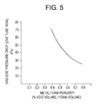
FIG. 5 illustrates the porosity versus back pressure of the metal foam segments ofFIG. 4 ; and -
FIG. 6 is a sectional view taken along line 6-6 inFIG 3 that illustrates the flow performance of the metal foam segments. - Referring now to the drawings, in which like numerals indicate like elements throughout the views,
FIG. 1 shows an exemplary embodiment of a single shaft, combinedcycle power plant 10. The combined cycle power plant includes agas turbine system 12, asteam turbine system 14 and agenerator 16 that is driven by the gas and steam turbines to generate electricity. The gas turbine system includes, in serial flow communication, a multistageaxial compressor 18, acombustor 20, and amulti-stage turbine 22. Thegas turbine system 12 and thesteam turbine system 14 are thermally connected through HRSG 24. The HRSG 24 is a heat exchanger configured to include aduct 28 for receipt and confinement of gasturbine exhaust gas 30 exiting themulti-stage turbine 22. Bundles ofheat transfer tubes 32 are disposed within theduct 28 of theHRSG 24 and are adapted to receive feed water 34 (condensate from steam turbine condenser 15) that is circulated through the tubes by thefeed water pump 36. As thefeed water 34 passes through theheat transfer tubes 32, heat from the gasturbine exhaust gas 30 passing through theHRSG duct 28 is transferred to the water, creating steam. The steam is supplied to, and drives, thesteam turbine 14, through themain steam piping 38. In addition, the steam from the HRSG may also be supplied to a process steam system (not shown). - Within the
duct 28 of HRSG 24 the exterior of theheat transfer tubes 32 represent the "hot side" surface area while the interior, or wet side, of the heat transfer tubes represent the "cold side" surface area. Enhanced transfer of heat between the hot and cold side surface areas of the HRSG will operate to increase the performance and economics of the combinedcycle power plant 10. Referring toFIG. 2 , a portion of theheat transfer tubes 32 is shown. In an exemplary embodiment of the invention a cellular material, such as metal foam extendedsurface 40, surrounds theheat transfer tubes 32. The metal foam extended surface is comprised of a relatively new class of materials having low density, high surface area and good strength. The metal foam extended surface may be formed from various powder metals and, with varying porosity. - Controlling the material properties and configuration of the metal foam extended
surface 40 is an important aspect of the invention in that the pressure drop of the gasturbine exhaust gas 30 passing through theHRSG duct 28 is a consideration in the design of the HRSG. High pressure drops across the bundles ofheat transfer tubes 32 will reduce the power output of thegas turbine system 12. As indicated in the plot shown, studies show that metal foam with appropriate porosity and density, which relates directly to pressure drop, can achieve lower pressure drop. Additionally, due to the unique structural characteristics of the metal foam, it has sound and vibration absorptive characteristics that are useful in relieving acoustical and vibration issues in the HRSG 24 and may allow for reduction or elimination of costly silencers and acoustic baffles used to modify the acoustic characteristics of the HRSG. - Referring to
FIGS. 2 ,3 and 4 , in an exemplary embodiment the metal foam extendedsurface 40 is defined by a series ofmetal foam segments 42 having a relatively discshaped configuration with an axially extending opening 45 and interior andexterior surfaces heat transfer tube 32 therein. The diameter "d" closely matches the outside diameter of theheat transfer tubes 32 such that when ametal foam segment 42 is installed onto a tube, surface area contact between theinterior surface 44 of the segment and theouter surface 52 of theheat transfer tube 32 is high. Once mounted on the heat transfer tubes, themetal foam segments 42 are attached using appropriate metallurgical joining techniques such as brazing, welding, diffusion bonding or other suitable methods. - The cylindrical,
metal foam segments 42 of the metal foam extendedsurface 40 operates to increase the rate of heat transfer from the gas turbine exhaust gas passing through theHRSG duct 28 to the water/steam 35 circulating in theheat transfer tubes 32. At the same time, exhaust gas backpressure experienced by the gas turbine can be maintained at acceptable levels. For example, eachmetal foam segment 42 has an axial height "h" and is preferably spaced from adjacent segments by an axial distance "g". Backpressure within theHRSG duct 28 has been found to fall within a desirable range when the ratio of the metal foam segment height "h" to the segment spacing "g" is within a range of greater than 0 to about 50 (i.e. 0 < h/g < 50). In addition, heat transfer reaches satisfactory levels when the ratio of the metal foam segment outer diameter "D" to the segment inner diameter "d" is within a range of about 1.2 to about 10 (i.e. 1.2 < D / d <10). - As indicated, due to the high surface area of metal foam, the overall heat transfer from the gas
turbine exhaust gas 30 to the water/steam 35 is enhanced significantly. Additionally, due to the non-smooth surface characteristics of themetal foam segments 42,FIG. 6 , the gas turbine exhaust gas flowing through theHRSG duct 28 will produce asmaller wake area 54, as compared with a conventionally finned tube, due to delayed flow separation. Thesmaller wake area 54 is a result of a turbulent boundary layer directly adjacent theexterior surface 46 and it operates to reduce backpressure through theHRSG 24. It has been determined that the benefit of delayed flow separation can be achieved when theheat transfer tubes 32 having metal foam extended surfaces are installed in theduct 28 ofHRSG 24 such that they have a ratio of frontal spacing "T" (transverse pitch) to metal foam segment outside diameter "D" within the range of about 1.05 to about 2 (i.e. 1.05 < T / D < 2), and a ratio of axial spacing "L" (longitudinal pitch) to metal foam segment outside diameter "D" within the range of about 0.2 to about 1.5 (i.e. 0.2 < L / D < 1.5). - While the described
metal foam segments 42 have been generally described as cylindrical in configuration, the present invention contemplates segments in a variety of shapes and sizes. It is contemplated that the configuration and spacing of themetal foam segments 42 will be selected to efficiently transfer heat to theheat transfer tubes 32 while lowering the gas turbine exhaust backpressure within theduct 28 of theHRSG 24. In addition, while the combinedcycle power plant 10 has been described having a single shaft configuration with a single gas turbine, steam turbine and generator, any number of application driven variations are also contemplated. For example it is contemplated that the invention has similar applicability to multiple shaft, combined cycle power plants and cogeneration power plants. The invention may be used in natural circulation, forced circulation and once through HRSGs configured with horizontal and/or vertical heat transfer tubes with gas turbine exhaust gas flow in horizontal and/or vertical directions. The HRSG tube arrangement may be either in-line or staggered and the HRSG may be either unfired or supplementary fired. - The written description uses examples to disclose the invention, including the best mode, and also to enable any person skilled in the art to practice the invention, including making and using any devices or systems and performing any incorporated methods. The patentable scope of the invention is defined by the claims, and may include other examples that occur to those skilled in the art. Such other examples are intended to be within the scope of the claims if they have structural elements that do not differ from the literal language of the claims, or if they include equivalent structural elements with insubstantial differences from the literal language of the claims.
Claims (12)
- A combined cycle power plant (10) including at least one gas turbine (12) and at least one steam turbine (14) thermally connected by a heat recovery steam generator (24), the steam generator comprising:a duct (28) configured to receive and confine gas turbine exhaust gas (30) from the at least one gas turbine (12);heat transfer tubes (32) disposed within the duct (28) and having exterior surfaces for fluid communication with the gas turbine exhaust gas (30) and interior surfaces configured for circulatory fluid communication with water and/or steam (35); anda cellular extended surface (40) attached to exterior surfaces of the heat transfer tubes (32) and operable to increase heat transfer from the hot combustion exhaust gas (30) to the water and/or steam (35).
- The combined cycle power plant (10) of claim 1, the cellular extended surface (40) comprising a series of spaced apart metal foam segments (42).
- The combined cycle power plant (10) of claim 2, the spaced apart metal foam segments (42) having an axial height and an axial spacing therebetween, wherein the ratio of the metal foam segment height to the axial spacing therebetween is within a range of greater than 0 to about 50.
- The combined cycle power plant (10) of claim 2, the spaced apart metal foam segments having an outer diameter and an inner diameter wherein the ratio of the metal foam segment outer diameter to the metal foam segment inner diameter is within a range of about 1.2 to about 10.
- The combined cycle power plant (10) of any of the preceding claims, the heat transfer tubes (32) having a frontal spacing (transverse pitch) in the duct (28) such that the ratio of the frontal spacing to the metal foam segment outside diameter is within the range of about 1.05 to about 2.
- The combined cycle power plant (10) of claim 5, the heat transfer tubes (32) having an axial spacing (longitudinal spacing) in the duct (28) such that the ratio of the axial spacing to the metal foam segment outside diameter is within the range of about 0.2 to about 1.5.
- A method of configuring a combined cycle power plant heat recovery steam generator (24) comprising the steps of:configuring a duct (28) to receive and confine gas turbine exhaust gas (30) from at least one gas turbine (12);disposing a series of heat transfer tubes (32) in the duct (28) such that the heat transfer tubes (32) are configured to receive a water and/or steam (35) therein; andapplying to an exterior surface of the heat transfer tubes (32) a cellular material (40) such that the cellular material is operable to increase heat transfer, when the heat transfer tube (32) is exposed to the gas turbine exhaust gas (30), from the gas turbine exhaust gas to the water and/or steam (35).
- The method of claim 7, further comprising the steps of configuring the cellular material as a series of metal foam segments (42) having axially extending openings (45) for engagement with the exterior surface of the heat transfer tubes (32); and
mounting the series of metal foam segments (42) on the heat transfer tubes (32) in an axially spaced apart relationship. - The method of claim 8, further comprising the steps of configuring the metal foam segments (42) to have an axial height such that the ratio of the metal foam segment axial height to the axial spacing therebetween is within a range of greater than 0 to about 50.
- The method of claim 8, further comprising the steps configuring the metal foam segments (42) to have an outer diameter such that the ratio of the metal foam segment (42) outer diameter to the diameter of the axially extending openings is within a range of about 1.2 to about 10.
- The method of claim 8, further comprising the steps of arranging the heat transfer tubes within the duct such that the ratio of the frontal spacing (transverse pitch) between the heat transfer tubes to the metal foam segment outside diameter is within the range of about 1.05 to about 2.
- The method of claim 8, further comprising the steps of arranging the heat transfer tubes axially within the duct such that the ratio of the axial spacing (longitudinal pitch) to the metal foam segment outside diameter is within the range of about 0.2 to about 1.5.
Applications Claiming Priority (1)
| Application Number | Priority Date | Filing Date | Title |
|---|---|---|---|
| US12/265,228 US8408003B2 (en) | 2008-11-05 | 2008-11-05 | Combined cycle power plant |
Publications (1)
| Publication Number | Publication Date |
|---|---|
| EP2423468A2 true EP2423468A2 (en) | 2012-02-29 |
Family
ID=42129769
Family Applications (1)
| Application Number | Title | Priority Date | Filing Date |
|---|---|---|---|
| EP09174687A Withdrawn EP2423468A2 (en) | 2008-11-05 | 2009-10-30 | Combined cycle power plant |
Country Status (4)
| Country | Link |
|---|---|
| US (1) | US8408003B2 (en) |
| EP (1) | EP2423468A2 (en) |
| JP (1) | JP2010112375A (en) |
| CN (1) | CN101737107A (en) |
Families Citing this family (8)
| Publication number | Priority date | Publication date | Assignee | Title |
|---|---|---|---|---|
| DE102010040249A1 (en) * | 2010-09-03 | 2012-03-08 | Man Diesel & Turbo Se | Double walled pipe |
| CN103517967B (en) * | 2011-07-14 | 2016-01-20 | 三菱日立电力系统株式会社 | Gas cooler, gasification furnace and carbonaceous fuel gasifying combined generating device |
| US9494086B2 (en) * | 2014-02-28 | 2016-11-15 | General Electric Company | Systems and methods for improved combined cycle control |
| US20170167389A1 (en) * | 2015-12-15 | 2017-06-15 | General Electric Company | System and Method for Controlling Gas Turbine Exhaust Energy Via Exhaust Gas Damper and Compressed Gas Supply |
| US11225907B2 (en) | 2016-02-11 | 2022-01-18 | General Electric Company | Gas turbine engine pipe cover |
| US10907511B2 (en) | 2016-09-20 | 2021-02-02 | General Electric Company | System and method for recovering turbine system extractions |
| US20210389061A1 (en) * | 2020-06-11 | 2021-12-16 | Ut-Battelle, Llc | Heat exchange apparatus and method |
| EP3929410B1 (en) | 2020-06-23 | 2022-10-26 | General Electric Technology GmbH | Exhaust duct for a gas turbine engine |
Family Cites Families (13)
| Publication number | Priority date | Publication date | Assignee | Title |
|---|---|---|---|---|
| US3095255A (en) * | 1960-04-25 | 1963-06-25 | Carrier Corp | Heat exchange apparatus of the evaporative type |
| US3442324A (en) * | 1967-03-06 | 1969-05-06 | American Mach & Foundry | Heat recovery device for turbine gases |
| US3543843A (en) * | 1968-08-20 | 1970-12-01 | Hudson Products Corp | Air cooled condenser apparatus |
| US5441716A (en) * | 1989-03-08 | 1995-08-15 | Rocky Research | Method and apparatus for achieving high reaction rates |
| US6234245B1 (en) | 1998-07-02 | 2001-05-22 | Fintube Technologies, Inc. | Aero curve fin segment |
| US6019070A (en) * | 1998-12-03 | 2000-02-01 | Duffy; Thomas E. | Circuit assembly for once-through steam generators |
| US6709739B1 (en) * | 1999-06-03 | 2004-03-23 | Case Western Reserve University | Closed cell metal composites |
| US6499302B1 (en) | 2001-06-29 | 2002-12-31 | General Electric Company | Method and apparatus for fuel gas heating in combined cycle power plants |
| NL1020708C2 (en) * | 2002-05-29 | 2003-12-02 | Andries Meuzelaar | Device for transferring heat. |
| CN1703599A (en) * | 2002-10-04 | 2005-11-30 | 鲁特/埃里克森有限公司 | Once-through evaporator for a steam generator |
| US20050076644A1 (en) | 2003-10-08 | 2005-04-14 | Hardwicke Canan Uslu | Quiet combustor for a gas turbine engine |
| NL1027646C2 (en) * | 2004-12-03 | 2006-06-07 | Andries Meuzelaar | Heat exchanger for motorized transport device e.g. racing car, aircraft, has thermally conductive open-cell metal foam with number of pores per inch (ppi) that lies between 2 and 20 and thickness that lies between 5 and 50 millimeters |
| US8281564B2 (en) * | 2009-01-23 | 2012-10-09 | General Electric Company | Heat transfer tubes having dimples arranged between adjacent fins |
-
2008
- 2008-11-05 US US12/265,228 patent/US8408003B2/en active Active
-
2009
- 2009-10-28 JP JP2009247158A patent/JP2010112375A/en active Pending
- 2009-10-30 EP EP09174687A patent/EP2423468A2/en not_active Withdrawn
- 2009-11-05 CN CN200910212267A patent/CN101737107A/en active Pending
Also Published As
| Publication number | Publication date |
|---|---|
| US20100107595A1 (en) | 2010-05-06 |
| CN101737107A (en) | 2010-06-16 |
| JP2010112375A (en) | 2010-05-20 |
| US8408003B2 (en) | 2013-04-02 |
Similar Documents
| Publication | Publication Date | Title |
|---|---|---|
| US8408003B2 (en) | Combined cycle power plant | |
| JP4322902B2 (en) | Solar power generation equipment and heat medium supply equipment | |
| RU2620309C2 (en) | Device and method for heat recovery steam generator close conjunction with gas turbine | |
| US4316435A (en) | Boiler tube silencer | |
| JP2009185820A (en) | Exhaust stack and power generation system for improving gas turbine output | |
| US11879691B2 (en) | Counter-flow heat exchanger | |
| JP4549868B2 (en) | Waste heat boiler | |
| US20100243228A1 (en) | Method and Apparatus to Effect Heat Transfer | |
| KR20110128849A (en) | Continuous Flow Evaporator | |
| MY134345A (en) | Device for cooling coolant in a gas turbine (2) and gas and steam turbine with said device | |
| KR20120027021A (en) | Continuous evaporator | |
| EP2275650A1 (en) | Combined cycle power plant | |
| US20120024241A1 (en) | Continuous evaporator | |
| JP2010048546A (en) | Dimple and serrated molded finned tube structure | |
| EP2530420A2 (en) | Fin and tube heat exchanger | |
| US20150075166A1 (en) | Sound damper for evaporation channels in steam power plants with air condensers | |
| KR101662348B1 (en) | Continuous evaporator | |
| US8857183B2 (en) | Steam turbine, power plant and method for operating steam turbine | |
| US20120186253A1 (en) | Heat Recovery Steam Generator Boiler Tube Arrangement | |
| JP2019143917A (en) | Evaporator, waste heat recovery boiler with the same, and evaporator modification method | |
| JP2002286379A (en) | Steam / hot water generator | |
| RU2360181C1 (en) | High-pressure heater of regeneration system of steam turbine | |
| CN214250700U (en) | Module combined heat exchanger for steam generating device | |
| KR20130090765A (en) | Method of manufacturing steam generator tube | |
| JP2017194223A (en) | Heat exchanger |
Legal Events
| Date | Code | Title | Description |
|---|---|---|---|
| AK | Designated contracting states |
Kind code of ref document: A2 Designated state(s): AT BE BG CH CY CZ DE DK EE ES FI FR GB GR HR HU IE IS IT LI LT LU LV MC MK MT NL NO PL PT RO SE SI SK SM TR |
|
| AX | Request for extension of the european patent |
Extension state: AL BA RS |
|
| PUAI | Public reference made under article 153(3) epc to a published international application that has entered the european phase |
Free format text: ORIGINAL CODE: 0009012 |
|
| STAA | Information on the status of an ep patent application or granted ep patent |
Free format text: STATUS: THE APPLICATION IS DEEMED TO BE WITHDRAWN |
|
| 18D | Application deemed to be withdrawn |
Effective date: 20140501 |