EP2423458A2 - Condenser for Power Plant - Google Patents
Condenser for Power Plant Download PDFInfo
- Publication number
- EP2423458A2 EP2423458A2 EP10156208A EP10156208A EP2423458A2 EP 2423458 A2 EP2423458 A2 EP 2423458A2 EP 10156208 A EP10156208 A EP 10156208A EP 10156208 A EP10156208 A EP 10156208A EP 2423458 A2 EP2423458 A2 EP 2423458A2
- Authority
- EP
- European Patent Office
- Prior art keywords
- cooling
- coolant
- condenser
- power plant
- steam turbine
- Prior art date
- Legal status (The legal status is an assumption and is not a legal conclusion. Google has not performed a legal analysis and makes no representation as to the accuracy of the status listed.)
- Withdrawn
Links
- 238000001816 cooling Methods 0.000 claims abstract description 149
- 239000002826 coolant Substances 0.000 claims abstract description 83
- 238000000034 method Methods 0.000 claims description 10
- 238000011144 upstream manufacturing Methods 0.000 claims description 7
- 239000000498 cooling water Substances 0.000 claims description 4
- XLYOFNOQVPJJNP-UHFFFAOYSA-N water Substances O XLYOFNOQVPJJNP-UHFFFAOYSA-N 0.000 description 4
- 230000001143 conditioned effect Effects 0.000 description 2
- 238000010586 diagram Methods 0.000 description 2
- 239000000446 fuel Substances 0.000 description 2
- 239000007788 liquid Substances 0.000 description 2
- 230000009467 reduction Effects 0.000 description 2
- 230000004075 alteration Effects 0.000 description 1
- 230000015572 biosynthetic process Effects 0.000 description 1
- 238000002485 combustion reaction Methods 0.000 description 1
- 238000009833 condensation Methods 0.000 description 1
- 230000005494 condensation Effects 0.000 description 1
- 230000000694 effects Effects 0.000 description 1
- 238000005755 formation reaction Methods 0.000 description 1
- 238000012423 maintenance Methods 0.000 description 1
- 238000007789 sealing Methods 0.000 description 1
- 238000004513 sizing Methods 0.000 description 1
- 238000006467 substitution reaction Methods 0.000 description 1
Images
Classifications
-
- F—MECHANICAL ENGINEERING; LIGHTING; HEATING; WEAPONS; BLASTING
- F28—HEAT EXCHANGE IN GENERAL
- F28B—STEAM OR VAPOUR CONDENSERS
- F28B1/00—Condensers in which the steam or vapour is separate from the cooling medium by walls, e.g. surface condenser
- F28B1/02—Condensers in which the steam or vapour is separate from the cooling medium by walls, e.g. surface condenser using water or other liquid as the cooling medium
-
- F—MECHANICAL ENGINEERING; LIGHTING; HEATING; WEAPONS; BLASTING
- F01—MACHINES OR ENGINES IN GENERAL; ENGINE PLANTS IN GENERAL; STEAM ENGINES
- F01K—STEAM ENGINE PLANTS; STEAM ACCUMULATORS; ENGINE PLANTS NOT OTHERWISE PROVIDED FOR; ENGINES USING SPECIAL WORKING FLUIDS OR CYCLES
- F01K9/00—Plants characterised by condensers arranged or modified to co-operate with the engines
- F01K9/003—Plants characterised by condensers arranged or modified to co-operate with the engines condenser cooling circuits
-
- F—MECHANICAL ENGINEERING; LIGHTING; HEATING; WEAPONS; BLASTING
- F28—HEAT EXCHANGE IN GENERAL
- F28B—STEAM OR VAPOUR CONDENSERS
- F28B11/00—Controlling arrangements with features specially adapted for condensers
-
- F—MECHANICAL ENGINEERING; LIGHTING; HEATING; WEAPONS; BLASTING
- F28—HEAT EXCHANGE IN GENERAL
- F28F—DETAILS OF HEAT-EXCHANGE AND HEAT-TRANSFER APPARATUS, OF GENERAL APPLICATION
- F28F2265/00—Safety or protection arrangements; Arrangements for preventing malfunction
- F28F2265/10—Safety or protection arrangements; Arrangements for preventing malfunction for preventing overheating, e.g. heat shields
Definitions
- the subject matter disclosed herein relates to a condenser for a power plant.
- a gas turbine engine In combined cycle power plants, a gas turbine engine generates power from the heat generated by the combustion of fuel and air. The heat is then reused to generate additional power as a result of the generation of steam that is introduced into steam turbines. Steam turbine discharge is then condensed in a condenser.
- a condenser includes a body through which steam turbine discharge flows over cooling members and in which condensation occurs.
- Ready-start conditions refer to several power plant characteristics including, but not limited to, the ability of a combined cycle power plant condenser to cool steam turbine discharge during shut down times. Steam discharge during shutdown is often limited to a small amount used for sealing the steam turbine against air ingress while the condenser is under vacuum. With that said, the cooling members of the condenser are generally ill equipped to condense the reduced quantities of steam turbine discharge that is produced during the shut down times. Because the normal condenser coolant pump is generally sized for 33% to 100% full steam flow, the need to run a pump to pump coolant to the cooling members during the shut down times is costly and inefficient.
- a condenser includes a body into and through which steam turbine discharge is able to flow, and first and second cooling members disposed in the body, wherein the first and second cooling members are each independently receptive of first and second coolant, respectively, the first cooling member, being receptive of the first coolant, is configured to cool the discharge during at least a first cooling operation, and the second cooling member, being receptive of the second coolant, is configured to cool the discharge during a second cooling operation.
- a power plant includes a condenser body, into and through which steam turbine discharge is able to flow and in which first and second cooling members are disposed, the first and second cooling members each being independently receptive of first and second coolant, respectively, and configured to respectively cool the steam turbine discharge during at least a first cooling operation and a second cooling operation, a coolant source, a first pump, coupled to the coolant source and the first cooling member, which is configured to pump the first coolant to the first cooling member during at least the first cooling operation, and a second pump, coupled to the coolant source and the second cooling member, which is configured to pump the second coolant to the second cooling member during the second cooling operation.
- a method of operating a power plant including a condenser body through which steam turbine discharge is able to flow, includes supplying a first coolant to a first cooling member disposed within the condenser body to cool the steam turbine discharge during at least a first cooling operation, supplying a second coolant to a second cooling member disposed within the condenser body to cool the steam turbine discharge during a second cooling operation, timing a duration of each of the first and second cooling operations, and alternating an engagement of the first and second cooling operations in accordance with the timing, preselected scheduling and current conditions.
- a steam cycle cooling subsystem for a combined cycle power plant or any other plant employing a steam cycle 10 is provided.
- the power plant 10 includes a gas turbine engine and a steam turbine or other means of generating steam.
- the steam turbine generates power from steam and produces steam turbine discharge, such as excess steam, that is condensed.
- the power plant 10 is able to operate continuously or in cycles of active and shut down states with relatively fast start-up characteristics.
- the power plant 10, being fast start capable, requires less time to achieve a significant load in the active state and is therefore more efficient.
- the power plant 10 includes a condenser 20 in which a condenser vacuum is maintained.
- the condenser 20 includes an inlet 40, a condenser body 50 and a hotwell 60.
- the steam turbine discharge enters the condenser 20 through the inlet 40 and proceeds to flow through an interior of the condenser body 50 where it is conditioned and cooled.
- As the steam turbine discharge is conditioned and cooled in the condenser body 50, it is condensed and collects as liquid water in the hotwell 60 and becomes available for further use in the power plant 10.
- the normal conditions refer to those periods during which the power plant 10 is in the active state.
- steam turbine discharge continues to enter the condenser 20 and, in order to maintain ready-start conditions that enable the power plant 10 to exhibit the fast start-up characteristics, the condenser vacuum still needs to be maintained. As such, it is necessary to continue to condense steam turbine discharge within the condenser body 50 even while the power plant 10 is shut down.
- a first cooling member 80 is disposed within the condenser body 50 and is configured to cool the steam turbine discharge during at least a first cooling operation, such as the maintenance of the ready-start conditions.
- a second cooling member 90 is also disposed within the condenser body 50 and is configured to cool the steam turbine discharge during a second cooling operation, such as operation of the power plant 10 in the active state.
- the first and second cooling members 80 and 90 are each positioned within the condenser body 50 such that the steam turbine discharge comes into contact with their respective surfaces.
- the first and second cooling members are each independently receptive of first and second supplies of coolant, such as water, respectively.
- the first cooling member 80 may be disposed within the condenser body 50 at a position which is upstream from a position of the second cooling member 90.
- this arrangement is merely exemplary and it is understood that the first cooling member 80 may also be disposed downstream from the second cooling member 90 or, in accordance with another embodiment, the first and second cooling members 80 and 90 may overlap with one another as long as they remain independently receptive of the first and second supplies of the coolant.
- the condenser body 50 may also include a dummy member 70.
- the dummy member 70 is generally disposed upstream from the first and second cooling member 80 and 90 and is configured to condition and/or initially cool the steam turbine discharge. With its upstream location, the dummy member 70 serves to protect the first and second cooling members 80 and 90 from damage resulting from contact with, e.g., very hot steam turbine discharge, discharge from a steam bypass system and/or any other dangerous matter entering the condenser body 50.
- the dummy member 70 and the first and second cooling members 80 and 90 each comprise a plurality of tubes 71, 81 and 91, respectively, which can be arranged in similar and/or varied formations relative to one another. That is, the dummy member 70 may include a set of horizontally arrayed tubes, the first cooling member 80 may include a set of vertically and horizontally aligned tubes and the second cooling member 90 may include a set of vertically and horizontally staggered tubes.
- the tubes are generally hollow and, at least in the case of the first and second cooling members 80 and 90, define interiors in which the first and second coolant supplies are to be received.
- the tubes of the first cooling member 80 include ready condition hold tubes, and the tubes of the second cooling member 90 include main cooling water tubes.
- a size of the first cooling member 80 may be significantly smaller than that of the second cooling member 90.
- an amount of the first coolant supply need not be equal to that of the second coolant supply and is, in fact, significantly smaller. As such, power required to supply the first cooling member 80 with the first coolant supply is correspondingly reducible.
- a size of the first cooling member 80 is sufficient to be adequate for cooling steam during the steam turbine shut down state with relatively good water distribution and with a pump of complimentary size offering considerable power savings over a main coolant pump.
- the power plant may further include a coolant source 100 and a system whereby the first and second coolant supplies are deliverable to the first and second cooling members 80 and 90.
- the coolant source 100 provides for a supply of the coolant from which the first and second coolant supplies are drawn.
- the coolant source 100 may include a cooling tower, a shown in FIG. 1 , or a trough source, such as a lake, a river or an ocean.
- the system may include a first pump 110 and/or a second pump 120 along with first and/or second piping 130 and 135.
- the first pump 110 is coupled to the coolant source 100 and, via optional valve 150, to the first cooling member 80. With this arrangement, the first pump 110 is configured to pump the first coolant to the first cooling member 80 during at least the first cooling operation.
- the second pump 120 is coupled to the coolant source 100 and, via optional valve 151, to the second cooling member 90 and is configured to pump the second coolant to the second cooling member 90 during the second cooling operation.
- the first piping 130 is jointly and/or separately coupled to the first and second cooling members 80 and 90 and to the coolant source 100 and is configured to return the coolant to the coolant source 100.
- the second piping 135 is jointly and/or separately coupled to the coolant source 100 and to the first and second pumps 110 and 120 and is configured to transport the coolant from the coolant source 100 to the pumps 110 and 120.
- the second pump 120 has a larger capacity than the first pump 110 and is therefore employed during the activate state of the power plant 10 to pump the second supply of the coolant to the second cooling member 90.
- the first pump 110 requires less power to operate than the second pump.
- the condenser vacuum can be maintained with the power plant 10 shut down at a reduced operating cost.
- a method of operating a power the plant 10, including a condenser body 50 through which steam turbine discharge is able to flow includes supplying a first coolant to a first cooling member 80, which is disposed within the condenser body 50, to cool the steam turbine discharge during at least a first cooling operation, supplying a second coolant to a second cooling member 90, which is disposed within the condenser body 50, to cool the steam turbine discharge during a second cooling operation, timing a duration of each of the first and second cooling operations and alternating an engagement of the first and second cooling operations in accordance with the timing, preselected scheduling and current conditions.
- the powerplant 10 may be operated in cycles of shut down and active states with the active state being in effect, for example, 5 days per week and 16 hours per day on those active days.
- the power plant 10 may be understood as, at some point, initially operating in the active state (operation 200) during which the second coolant is supplied to the second cooling member 90 (operation 205).
- operation 200 the active state
- operation 205 the second coolant is supplied to the second cooling member 90
- operation 210 Once the time for the active state is determined to have ended (operation 210), the power plant 10 shut down state is initiated (operation 220) and, for the duration of the shut down state, the first coolant supply is supplied to the first cooling member 80 (operation 230).
- shut down state if current conditions, such as an instance of unexpected power reduction or loss of a wind turbine or solar power source or other power source subject to uncontrolled power reductions, or some other alternate power generating apparatus, necessitates that the power plant 10 be returned to the active state (operation 240), control returns to operation 200.
Landscapes
- Engineering & Computer Science (AREA)
- Mechanical Engineering (AREA)
- General Engineering & Computer Science (AREA)
- Chemical & Material Sciences (AREA)
- Combustion & Propulsion (AREA)
- Engine Equipment That Uses Special Cycles (AREA)
- Control Of Turbines (AREA)
Abstract
Description
- The subject matter disclosed herein relates to a condenser for a power plant.
- In combined cycle power plants, a gas turbine engine generates power from the heat generated by the combustion of fuel and air. The heat is then reused to generate additional power as a result of the generation of steam that is introduced into steam turbines. Steam turbine discharge is then condensed in a condenser. Generally, such a condenser includes a body through which steam turbine discharge flows over cooling members and in which condensation occurs.
- Currently, many combined cycle power plants are operated and shut down in cycles to save fuel and energy costs during period of low power requirements, such as nights and weekends. As such, the combined cycle power plants need to go through start-up operations frequently in accordance with their respective schedules and, in some cases, in response to unexpected power requirements. Start-up operations are, however, inefficient and time consuming so it is typically a goal of power plant designers to shorten start-up times as much as possible.
- As an example, some combined cycle power plants are now maintained with ready-start conditions during shut down times. Ready-start conditions refer to several power plant characteristics including, but not limited to, the ability of a combined cycle power plant condenser to cool steam turbine discharge during shut down times. Steam discharge during shutdown is often limited to a small amount used for sealing the steam turbine against air ingress while the condenser is under vacuum. With that said, the cooling members of the condenser are generally ill equipped to condense the reduced quantities of steam turbine discharge that is produced during the shut down times. Because the normal condenser coolant pump is generally sized for 33% to 100% full steam flow, the need to run a pump to pump coolant to the cooling members during the shut down times is costly and inefficient. Due to the sizing of the condenser cooling members (tube bank) for full cooling water flow, flow from a small pump, although thermodynamically sufficient for cooling the shutdown steam flow, will not distribute evenly within the tube bank. The uneven distribution means some shutdown steam will not be cooled leading to excess temperature and pressure in the condenser.
- According to one aspect of the invention, a condenser is provided and includes a body into and through which steam turbine discharge is able to flow, and first and second cooling members disposed in the body, wherein the first and second cooling members are each independently receptive of first and second coolant, respectively, the first cooling member, being receptive of the first coolant, is configured to cool the discharge during at least a first cooling operation, and the second cooling member, being receptive of the second coolant, is configured to cool the discharge during a second cooling operation.
- According to another aspect of the invention, a power plant is provided and includes a condenser body, into and through which steam turbine discharge is able to flow and in which first and second cooling members are disposed, the first and second cooling members each being independently receptive of first and second coolant, respectively, and configured to respectively cool the steam turbine discharge during at least a first cooling operation and a second cooling operation, a coolant source, a first pump, coupled to the coolant source and the first cooling member, which is configured to pump the first coolant to the first cooling member during at least the first cooling operation, and a second pump, coupled to the coolant source and the second cooling member, which is configured to pump the second coolant to the second cooling member during the second cooling operation.
- According to yet another aspect of the invention, a method of operating a power plant, including a condenser body through which steam turbine discharge is able to flow, is provided and includes supplying a first coolant to a first cooling member disposed within the condenser body to cool the steam turbine discharge during at least a first cooling operation, supplying a second coolant to a second cooling member disposed within the condenser body to cool the steam turbine discharge during a second cooling operation, timing a duration of each of the first and second cooling operations, and alternating an engagement of the first and second cooling operations in accordance with the timing, preselected scheduling and current conditions.
- These and other advantages and features will become more apparent from the following description taken in conjunction with the drawings.
- There follows a detailed description of embodiments of the invention by way of example only with reference to the accompanying drawings, in which:
-
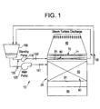
FIG. 1 is a schematic diagram of a combined cycle power plant; and -
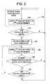
FIG. 2 is a flow diagram illustrating a method of operating a combined cycle power plant. - With reference to
FIG. 1 , a steam cycle cooling subsystem for a combined cycle power plant or any other plant employing asteam cycle 10 is provided. Thepower plant 10 includes a gas turbine engine and a steam turbine or other means of generating steam. The steam turbine generates power from steam and produces steam turbine discharge, such as excess steam, that is condensed. In the case of a combined cycle power plant, as will be described below, thepower plant 10 is able to operate continuously or in cycles of active and shut down states with relatively fast start-up characteristics. Thepower plant 10, being fast start capable, requires less time to achieve a significant load in the active state and is therefore more efficient. - For the steam turbine discharge to be condensed during normal conditions, the
power plant 10 includes acondenser 20 in which a condenser vacuum is maintained. Thecondenser 20 includes aninlet 40, acondenser body 50 and ahotwell 60. The steam turbine discharge enters thecondenser 20 through theinlet 40 and proceeds to flow through an interior of thecondenser body 50 where it is conditioned and cooled. As the steam turbine discharge is conditioned and cooled in thecondenser body 50, it is condensed and collects as liquid water in thehotwell 60 and becomes available for further use in thepower plant 10. - Generally, the normal conditions refer to those periods during which the
power plant 10 is in the active state. When thepower plant 10 is in the shut down state, however, steam turbine discharge continues to enter thecondenser 20 and, in order to maintain ready-start conditions that enable thepower plant 10 to exhibit the fast start-up characteristics, the condenser vacuum still needs to be maintained. As such, it is necessary to continue to condense steam turbine discharge within thecondenser body 50 even while thepower plant 10 is shut down. - A
first cooling member 80 is disposed within thecondenser body 50 and is configured to cool the steam turbine discharge during at least a first cooling operation, such as the maintenance of the ready-start conditions. Similarly, asecond cooling member 90 is also disposed within thecondenser body 50 and is configured to cool the steam turbine discharge during a second cooling operation, such as operation of thepower plant 10 in the active state. - The first and
second cooling members condenser body 50 such that the steam turbine discharge comes into contact with their respective surfaces. In addition, the first and second cooling members are each independently receptive of first and second supplies of coolant, such as water, respectively. Thus, as steam turbine discharge proceeds through thecondenser body 50 and contacts the surfaces of the first andsecond cooling members second cooling members hotwell 60. - As shown in
FIG. 1 , thefirst cooling member 80 may be disposed within thecondenser body 50 at a position which is upstream from a position of thesecond cooling member 90. However, this arrangement is merely exemplary and it is understood that thefirst cooling member 80 may also be disposed downstream from thesecond cooling member 90 or, in accordance with another embodiment, the first andsecond cooling members - The
condenser body 50 may also include adummy member 70. Thedummy member 70 is generally disposed upstream from the first andsecond cooling member dummy member 70 serves to protect the first andsecond cooling members condenser body 50. - The
dummy member 70 and the first andsecond cooling members tubes dummy member 70 may include a set of horizontally arrayed tubes, thefirst cooling member 80 may include a set of vertically and horizontally aligned tubes and thesecond cooling member 90 may include a set of vertically and horizontally staggered tubes. The tubes are generally hollow and, at least in the case of the first andsecond cooling members first cooling member 80 include ready condition hold tubes, and the tubes of thesecond cooling member 90 include main cooling water tubes. - When the
power plant 10 is in the shut down state, an amount of the steam turbine discharge entering thecondenser 20 is relatively greatly reduced from the amount entering thecondenser 20 during the active state of thepower plant 10. Thus, a size of thefirst cooling member 80 may be significantly smaller than that of thesecond cooling member 90. Similarly, an amount of the first coolant supply need not be equal to that of the second coolant supply and is, in fact, significantly smaller. As such, power required to supply thefirst cooling member 80 with the first coolant supply is correspondingly reducible. - That is, in accordance with embodiments, a size of the
first cooling member 80 is sufficient to be adequate for cooling steam during the steam turbine shut down state with relatively good water distribution and with a pump of complimentary size offering considerable power savings over a main coolant pump. - In accordance with a further aspect of the invention, the power plant may further include a
coolant source 100 and a system whereby the first and second coolant supplies are deliverable to the first andsecond cooling members coolant source 100 provides for a supply of the coolant from which the first and second coolant supplies are drawn. In this way, thecoolant source 100 may include a cooling tower, a shown inFIG. 1 , or a trough source, such as a lake, a river or an ocean. - In further embodiments, the system may include a
first pump 110 and/or asecond pump 120 along with first and/orsecond piping first pump 110 is coupled to thecoolant source 100 and, viaoptional valve 150, to thefirst cooling member 80. With this arrangement, thefirst pump 110 is configured to pump the first coolant to thefirst cooling member 80 during at least the first cooling operation. Thesecond pump 120 is coupled to thecoolant source 100 and, viaoptional valve 151, to thesecond cooling member 90 and is configured to pump the second coolant to thesecond cooling member 90 during the second cooling operation. Thefirst piping 130 is jointly and/or separately coupled to the first andsecond cooling members coolant source 100 and is configured to return the coolant to thecoolant source 100. Thesecond piping 135 is jointly and/or separately coupled to thecoolant source 100 and to the first andsecond pumps coolant source 100 to thepumps - The
second pump 120 has a larger capacity than thefirst pump 110 and is therefore employed during the activate state of thepower plant 10 to pump the second supply of the coolant to thesecond cooling member 90. Thefirst pump 110, on the other hand, requires less power to operate than the second pump. Thus, by using thefirst pump 110 to pump the first coolant supply to thefirst cooling member 80, the condenser vacuum can be maintained with thepower plant 10 shut down at a reduced operating cost. - With reference to
FIG. 2 , and in accordance with another aspect of the invention, a method of operating a power theplant 10, including acondenser body 50 through which steam turbine discharge is able to flow is provided. The method includes supplying a first coolant to afirst cooling member 80, which is disposed within thecondenser body 50, to cool the steam turbine discharge during at least a first cooling operation, supplying a second coolant to asecond cooling member 90, which is disposed within thecondenser body 50, to cool the steam turbine discharge during a second cooling operation, timing a duration of each of the first and second cooling operations and alternating an engagement of the first and second cooling operations in accordance with the timing, preselected scheduling and current conditions. - That is, as shown in
FIG. 2 , thepowerplant 10 may be operated in cycles of shut down and active states with the active state being in effect, for example, 5 days per week and 16 hours per day on those active days. As such, thepower plant 10 may be understood as, at some point, initially operating in the active state (operation 200) during which the second coolant is supplied to the second cooling member 90 (operation 205). Once the time for the active state is determined to have ended (operation 210), thepower plant 10 shut down state is initiated (operation 220) and, for the duration of the shut down state, the first coolant supply is supplied to the first cooling member 80 (operation 230). During the shut down state, if current conditions, such as an instance of unexpected power reduction or loss of a wind turbine or solar power source or other power source subject to uncontrolled power reductions, or some other alternate power generating apparatus, necessitates that thepower plant 10 be returned to the active state (operation 240), control returns tooperation 200. - While the invention has been described in detail in connection with only a limited number of embodiments, it should be readily understood that the invention is not limited to such disclosed embodiments. Rather, the invention can be modified to incorporate any number of variations, alterations, substitutions or equivalent arrangements not heretofore described, but which are commensurate with the spirit and scope of the invention. Additionally, while various embodiments of the invention have been described, it is to be understood that aspects of the invention may include only some of the described embodiments. Accordingly, the invention is not to be seen as limited by the foregoing description, but is only limited by the scope of the appended claims.
- For completeness, various aspects of the invention are now set out in the following numbered clauses:
- 1. A condenser, comprising:
- a body into and through which steam turbine discharge is able to flow; and
- first and second cooling members disposed in the body, wherein
- the first and second cooling members are each independently receptive of first and second coolant, respectively, the first cooling member, being receptive of the first coolant, is configured to cool the discharge during at least a first cooling operation, and the second cooling member, being receptive of the second coolant, is configured to cool the discharge during a second cooling operation.
- 2. The condenser according to
claim 1, wherein the first cooling member is disposed upstream from the second cooling member. - 3. The condenser according to claim 2, further comprising a dummy member, disposed in the body and upstream from the first cooling member, which is configured to condition the discharge.
- 4. The condenser according to
claim 1, wherein the dummy member and the first and second cooling members each comprise a plurality of tubes. - 5. The condenser according to claim 4, wherein the plurality of the tubes of the first cooling member comprise ready condition hold tubes, and the plurality of the tubes of the second cooling member comprise main cooling water tubes.
- 6. The condenser according to
claim 1, wherein an amount of the first coolant is less than that of the second coolant. - 7. The condenser according to
claim 1, wherein the first and second cooling operations are conducted during power plant shut down cycles and active power plant cycles, respectively. - 8. The condenser according to
claim 1, wherein an amount of the discharge to be cooled during the first cooling operation is less than that of the second cooling operation. - 9. A power plant, comprising:
- a condenser body, into and through which steam turbine discharge is able to flow and
- in which first and second cooling members are disposed, the first and second cooling members each being independently receptive of first and second coolant, respectively, and configured to respectively cool the steam turbine discharge during at least a first cooling operation and a second cooling operation;
- a coolant source;
- a first pump, coupled to the coolant source and the first cooling member, which is configured to pump the first coolant to the first cooling member during at least the first cooling operation; and
- a second pump, coupled to the coolant source and the second cooling member, which is configured to pump the second coolant to the second cooling member during the second cooling operation.
- 10. The power plant according to claim 9, wherein the coolant source comprises a cooling tower.
- 11. The power plant according to claim 9, wherein the coolant source comprises a trough source.
- 12. The power plant according to claim 9, further comprising first piping coupled to the first and second cooling members and to the coolant source.
- 13. The power plant according to claim 9, further comprising first piping separately coupled to the first and second cooling members and to the coolant source.
- 14. The power plant according to claim 9, further comprising second piping coupled to the coolant source and to the first and second pumps.
- 15. The power plant according to claim 9, further comprising second piping separately coupled to the coolant source and to the first and second pumps.
- 16. A method of operating a power plant, including a condenser body through which steam turbine discharge is able to flow, the method comprising:
- supplying a first coolant to a first cooling member disposed within the condenser body to cool the steam turbine discharge during at least a first cooling operation;
- supplying a second coolant to a second cooling member disposed within the condenser body to cool the steam turbine discharge during a second cooling operation;
- timing a duration of each of the first and second cooling operations; and
- alternating an engagement of the first and second cooling operations in accordance with the timing, preselected scheduling and current conditions.
- 17. The method according to claim 16, wherein the second cooling operation is engaged for a selected number of days each week for a selected number of hours each day.
- 18. The method according to claim 17, wherein the second cooling operation is additionally engaged as required by the current conditions.
Claims (15)
- A condenser (20), comprising:a body (50) into and through which steam turbine discharge is able to flow; andfirst and second cooling members (80, 90) disposed in the body (50), whereinthe first and second cooling members (80, 90) are each independently receptive of first and second coolant, respectively, the first cooling member (80), being receptive of the first coolant, is configured to cool the discharge during at least a first cooling operation, and the second cooling member (90), being receptive of the second coolant, is configured to cool the discharge during a second cooling operation.
- The condenser (20) according to claim 1, wherein the first cooling member (80) is disposed upstream from the second cooling member (90).
- The condenser (20) according to claim 2, further comprising a dummy member (70), disposed in the body (50) and upstream from the first cooling member (80), which is configured to condition the discharge.
- The condenser (20) according to any of the preceding claims, wherein the dummy member (70) and the first and second cooling members (80, 90) each comprise a plurality of tubes (71, 81, 91).
- The condenser (20) according to claim 4, wherein the plurality of the tubes (81) of the first cooling member (80) comprise ready condition hold tubes, and the plurality of the tubes (91) of the second cooling member (90) comprise main cooling water tubes.
- The condenser (20) according to any of the preceding claims, wherein an amount of the first coolant is less than that of the second coolant.
- The condenser (20) according to any of the preceding claims, wherein the first and second cooling operations are conducted during power plant shut down cycles and active power plant cycles, respectively.
- The condenser (20) according to any of the preceding claims, wherein an amount of the discharge to be cooled during the first cooling operation is less than that of the second cooling operation.
- A power plant (10), comprising:a condenser body (50), into and through which steam turbine discharge is able to flow and in which first and second cooling members (80, 90) are disposed, the first andsecond cooling members (80, 90) each being independently receptive of first andsecond coolant, respectively, and configured to respectively cool the steam turbine discharge during at least a first cooling operation and a second cooling operation;a coolant source (100);a first pump (110), coupled to the coolant source (100) and the first cooling member (80), which is configured to pump the first coolant to the first cooling member (80) during at least the first cooling operation; anda second pump (120), coupled to the coolant source (100) and the second cooling member (90), which is configured to pump the second coolant to the second cooling member (90) during the second cooling operation.
- The power plant according to claim 9, wherein the coolant source comprises a cooling tower.
- The power plant according to claim 9, wherein the coolant source comprises a trough source.
- The power plant according to any of claims 9 to 11, further comprising first piping coupled to the first and second cooling members and to the coolant source.
- The power plant according to any of claims 9 to 11, further comprising first piping separately coupled to the first and second cooling members and to the coolant source.
- The power plant according to any of claims 9 to 13, further comprising second piping coupled to the coolant source and to the first and second pumps.
- A method of operating a power plant (10), including a condenser body (50) through which steam turbine discharge is able to flow, the method comprising:supplying a first coolant to a first cooling member (80) disposed within the condenser body (50) to cool the steam turbine discharge during at least a first cooling operation;supplying a second coolant to a second cooling member (90) disposed within the condenser body (50) to cool the steam turbine discharge during a second cooling operation;timing a duration of each of the first and second cooling operations; andalternating an engagement of the first and second cooling operations in accordance with the timing, preselected scheduling and current conditions.
Applications Claiming Priority (1)
| Application Number | Priority Date | Filing Date | Title |
|---|---|---|---|
| US12/402,579 US8220266B2 (en) | 2009-03-12 | 2009-03-12 | Condenser for power plant |
Publications (2)
| Publication Number | Publication Date |
|---|---|
| EP2423458A2 true EP2423458A2 (en) | 2012-02-29 |
| EP2423458A3 EP2423458A3 (en) | 2013-12-25 |
Family
ID=42729569
Family Applications (1)
| Application Number | Title | Priority Date | Filing Date |
|---|---|---|---|
| EP10156208.0A Withdrawn EP2423458A3 (en) | 2009-03-12 | 2010-03-11 | Condenser for Power Plant |
Country Status (4)
| Country | Link |
|---|---|
| US (1) | US8220266B2 (en) |
| EP (1) | EP2423458A3 (en) |
| JP (1) | JP5600263B2 (en) |
| CN (1) | CN101900494B (en) |
Families Citing this family (9)
| Publication number | Priority date | Publication date | Assignee | Title |
|---|---|---|---|---|
| US20110146293A1 (en) * | 2009-12-23 | 2011-06-23 | General Electric Company | Method for connecting a starting means to a turbomachine |
| JP5773708B2 (en) * | 2011-03-31 | 2015-09-02 | 三菱重工業株式会社 | Heat exchanger and method for estimating remaining life of heat exchanger |
| EP2642089B1 (en) * | 2012-03-19 | 2016-08-24 | General Electric Technology GmbH | Method for operating a power plant |
| JP6208548B2 (en) * | 2013-11-06 | 2017-10-04 | 三菱日立パワーシステムズ株式会社 | Steam turbine forced cooling device, steam turbine device including the same, and steam turbine forced cooling method |
| EP2878907A1 (en) * | 2013-11-28 | 2015-06-03 | Alstom Technology Ltd | Integrated condenser |
| JP6198673B2 (en) * | 2014-05-15 | 2017-09-20 | 株式会社神戸製鋼所 | Thermal energy recovery device and control method |
| BR102014023072B1 (en) | 2014-09-13 | 2020-12-01 | Citrotec Indústria E Comércio Ltda | vacuum condensing system using evaporative condenser and air removal system coupled to thermoelectric condensation turbines |
| CN109306878B (en) * | 2018-10-21 | 2021-03-23 | 河南理工大学 | A power plant system with waste water heat recovery and return water functions |
| WO2020234772A1 (en) | 2019-05-20 | 2020-11-26 | Sabic Global Technologies B.V. | Online method for processing wax-containing crude methanol stream |
Family Cites Families (17)
| Publication number | Priority date | Publication date | Assignee | Title |
|---|---|---|---|---|
| US2982864A (en) * | 1956-05-21 | 1961-05-02 | Furreboe Anton | Improved heat cycle for power plants |
| US3831667A (en) * | 1971-02-04 | 1974-08-27 | Westinghouse Electric Corp | Combination wet and dry cooling system for a steam turbine |
| US3881548A (en) * | 1971-07-14 | 1975-05-06 | Westinghouse Electric Corp | Multi-temperature circulating water system for a steam turbine |
| JPS5716058Y2 (en) * | 1973-10-12 | 1982-04-03 | ||
| CA1040946A (en) * | 1975-06-16 | 1978-10-24 | Hudson Products Corporation | Steam condensing apparatus |
| US4168030A (en) * | 1976-10-22 | 1979-09-18 | Timmerman Robert W | Waste heat utilization system |
| US4156349A (en) * | 1977-09-19 | 1979-05-29 | Westinghouse Electric Corp. | Dry cooling power plant system |
| US4347705A (en) * | 1980-03-17 | 1982-09-07 | Mirante Arthur J | Closed fluid flow system for producing power |
| DE3172221D1 (en) * | 1980-07-01 | 1985-10-17 | Costain Petrocarbon | Producing power from a cryogenic liquid |
| US4506508A (en) * | 1983-03-25 | 1985-03-26 | Chicago Bridge & Iron Company | Apparatus and method for condensing steam |
| DE3460673D1 (en) * | 1983-06-09 | 1986-10-16 | Bbc Brown Boveri & Cie | Multi-stage steam generator condenser with reheating arrangements for the suppression of condensate under cooling |
| JPS62267508A (en) * | 1986-05-15 | 1987-11-20 | Mitsubishi Heavy Ind Ltd | Condenser mechanism |
| JP2002221395A (en) * | 2001-01-26 | 2002-08-09 | Ebara Corp | Cooling facility and method for steam condenser |
| US6481208B1 (en) * | 2001-10-01 | 2002-11-19 | Holtec International | External steam dump |
| US7610952B2 (en) * | 2006-03-27 | 2009-11-03 | Bharat Heavy Electricals Limited | Steam condenser with two-pass tube nest layout |
| US7926555B2 (en) * | 2006-06-27 | 2011-04-19 | Gea Power Cooling, Inc. | Series-parallel condensing system |
| DE102007038241A1 (en) * | 2007-08-13 | 2009-03-05 | SCHÄFER, Christian | Steam turbine system efficiency improving method for ship, involves cooling water in secondary side in coils, where heat transfer surface of coils is subjected primarily to cooling water to be cooled and secondarily to expanded coolant |
-
2009
- 2009-03-12 US US12/402,579 patent/US8220266B2/en not_active Expired - Fee Related
-
2010
- 2010-03-10 JP JP2010052476A patent/JP5600263B2/en not_active Expired - Fee Related
- 2010-03-11 EP EP10156208.0A patent/EP2423458A3/en not_active Withdrawn
- 2010-03-12 CN CN201010146877.3A patent/CN101900494B/en not_active Expired - Fee Related
Non-Patent Citations (1)
| Title |
|---|
| None |
Also Published As
| Publication number | Publication date |
|---|---|
| US20100229553A1 (en) | 2010-09-16 |
| CN101900494B (en) | 2014-03-12 |
| EP2423458A3 (en) | 2013-12-25 |
| CN101900494A (en) | 2010-12-01 |
| JP5600263B2 (en) | 2014-10-01 |
| US8220266B2 (en) | 2012-07-17 |
| JP2010216475A (en) | 2010-09-30 |
Similar Documents
| Publication | Publication Date | Title |
|---|---|---|
| US8220266B2 (en) | Condenser for power plant | |
| US20240167457A1 (en) | Offshore renewable energy power station | |
| US20110210555A1 (en) | Gas turbine driven electric power system with constant output through a full range of ambient conditions | |
| EP3059415B1 (en) | System and method for heating make-up working fluid of a steam system with engine fluid waste heat | |
| US20130199202A1 (en) | System and method for gas turbine inlet air heating | |
| US10830105B2 (en) | System and method for improving output and heat rate for a liquid natural gas combined cycle power plant | |
| JP6261956B2 (en) | High humidity gas turbine system | |
| CN104246151A (en) | Method for operating a gas and steam turbine system for frequency assistance | |
| US20120023942A1 (en) | Method for increasing the net electric power of solar thermal power stations | |
| US8267639B2 (en) | Systems and methods for providing compressor extraction cooling | |
| US20130199196A1 (en) | System and method for gas turbine part load efficiency improvement | |
| US8141336B1 (en) | Combined cycle power augmentation by efficient utilization of atomizing air energy | |
| EP3315735B1 (en) | System for higher plant efficiency | |
| US20090252598A1 (en) | Gas turbine inlet temperature suppression during under frequency events and related method | |
| Arakelyan et al. | Increased reliability, manoeuvrability and durability of steam turbines through the implementation of the generator driving mode | |
| US7640724B2 (en) | System and method for improving the heat rate of a turbine | |
| US10006310B2 (en) | Steam power plant with an additional flexible solar system for the flexible integration of solar energy | |
| US20210396159A1 (en) | Exhaust gas recirculation in gas and steam turbine plants | |
| RU2459293C1 (en) | Nuclear power station turbine plant (versions) | |
| CN220869486U (en) | Low-temperature low-pressure saturated steam waste heat power generation system | |
| US20150121871A1 (en) | Forced cooling in steam turbine plants | |
| EP2752566B1 (en) | Gas turbine cooling system, and gas turbine cooling method | |
| JP2007016791A (en) | Combined power plant and closed air cooled gas turbine system | |
| JP2015004300A (en) | Combined cycle power generation facility | |
| Lenev et al. | Optimization of HRSG Supply Unit and Consideration of Thermal Stress State of Critical Elements of Steam-Water Path at Variable GTU Modes |
Legal Events
| Date | Code | Title | Description |
|---|---|---|---|
| AK | Designated contracting states |
Kind code of ref document: A2 Designated state(s): AT BE BG CH CY CZ DE DK EE ES FI FR GB GR HR HU IE IS IT LI LT LU LV MC MK MT NL NO PL PT RO SE SI SK SM TR |
|
| AX | Request for extension of the european patent |
Extension state: AL BA ME RS |
|
| PUAI | Public reference made under article 153(3) epc to a published international application that has entered the european phase |
Free format text: ORIGINAL CODE: 0009012 |
|
| PUAL | Search report despatched |
Free format text: ORIGINAL CODE: 0009013 |
|
| AK | Designated contracting states |
Kind code of ref document: A3 Designated state(s): AT BE BG CH CY CZ DE DK EE ES FI FR GB GR HR HU IE IS IT LI LT LU LV MC MK MT NL NO PL PT RO SE SI SK SM TR |
|
| AX | Request for extension of the european patent |
Extension state: AL BA ME RS |
|
| RIC1 | Information provided on ipc code assigned before grant |
Ipc: F28B 1/02 20060101ALI20131121BHEP Ipc: F28B 11/00 20060101ALI20131121BHEP Ipc: F01K 9/00 20060101AFI20131121BHEP |
|
| 17P | Request for examination filed |
Effective date: 20140625 |
|
| RBV | Designated contracting states (corrected) |
Designated state(s): AT BE BG CH CY CZ DE DK EE ES FI FR GB GR HR HU IE IS IT LI LT LU LV MC MK MT NL NO PL PT RO SE SI SK SM TR |
|
| GRAP | Despatch of communication of intention to grant a patent |
Free format text: ORIGINAL CODE: EPIDOSNIGR1 |
|
| INTG | Intention to grant announced |
Effective date: 20190405 |
|
| STAA | Information on the status of an ep patent application or granted ep patent |
Free format text: STATUS: THE APPLICATION IS DEEMED TO BE WITHDRAWN |
|
| 18D | Application deemed to be withdrawn |
Effective date: 20190817 |