EP2423431A2 - Self-orienting croosover tool - Google Patents
Self-orienting croosover tool Download PDFInfo
- Publication number
- EP2423431A2 EP2423431A2 EP11250738A EP11250738A EP2423431A2 EP 2423431 A2 EP2423431 A2 EP 2423431A2 EP 11250738 A EP11250738 A EP 11250738A EP 11250738 A EP11250738 A EP 11250738A EP 2423431 A2 EP2423431 A2 EP 2423431A2
- Authority
- EP
- European Patent Office
- Prior art keywords
- internal
- port
- external
- sleeve
- tool
- Prior art date
- Legal status (The legal status is an assumption and is not a legal conclusion. Google has not performed a legal analysis and makes no representation as to the accuracy of the status listed.)
- Granted
Links
Images



Classifications
-
- E—FIXED CONSTRUCTIONS
- E21—EARTH OR ROCK DRILLING; MINING
- E21B—EARTH OR ROCK DRILLING; OBTAINING OIL, GAS, WATER, SOLUBLE OR MELTABLE MATERIALS OR A SLURRY OF MINERALS FROM WELLS
- E21B43/00—Methods or apparatus for obtaining oil, gas, water, soluble or meltable materials or a slurry of minerals from wells
- E21B43/02—Subsoil filtering
- E21B43/04—Gravelling of wells
- E21B43/045—Crossover tools
-
- E—FIXED CONSTRUCTIONS
- E21—EARTH OR ROCK DRILLING; MINING
- E21B—EARTH OR ROCK DRILLING; OBTAINING OIL, GAS, WATER, SOLUBLE OR MELTABLE MATERIALS OR A SLURRY OF MINERALS FROM WELLS
- E21B2200/00—Special features related to earth drilling for obtaining oil, gas or water
- E21B2200/06—Sleeve valves
-
- E—FIXED CONSTRUCTIONS
- E21—EARTH OR ROCK DRILLING; MINING
- E21B—EARTH OR ROCK DRILLING; OBTAINING OIL, GAS, WATER, SOLUBLE OR MELTABLE MATERIALS OR A SLURRY OF MINERALS FROM WELLS
- E21B2200/00—Special features related to earth drilling for obtaining oil, gas or water
- E21B2200/08—Down-hole devices using materials which decompose under well-bore conditions
Definitions
- granular materials in slurry form can be pumped into a wellbore to improve the well's production.
- the slurry can be part of a gravel pack operation and can have solid granular or pelletized materials (e.g., gravel).
- Operators pump the gravel slurry down the tubing string. Downhole, a cross-over tool with exit ports diverts the slurry from the tubing string to the wellbore annulus so the gravel can be placed where desired. Once packed, the gravel can strain produced fluid and prevent fine material from entering the production string.
- operators can pump high-pressure fracture fluid downhole during a fracturing operation to form fractures in the formation.
- This fracturing fluid typically contains a proppant to maintain the newly formed fractures open.
- a crossover tool on the production string can be used in the fracturing operation to direct the slurry of proppant into the wellbore annulus so it can interact with the formation.
- the slurry is viscous and can flow at a very high rate (e.g., above 10 bbls/min).
- the slurry's flow is highly erosive flow and can produce significant wear in the crossover tool even though the tool is typically made of 4140 steel or corrosion resistant alloys.
- the most severe damage occurs around the exit ports where the slurry exits the crossover tool and enters the inside of the production assembly.
- the crossover tool has inner and outer components that both have ports. As expected, any misalignment between such ports can aggravate wear as the slurry flows between them. If the wear is not managed properly, it can decrease the tool's tensile strength enough to cause failure under load and can also produce problems with sealing within the tool.
- a downhole crossover tool comprising: an external sleeve having a first axial bore and having an external port communicating with the first axial bore; and an internal sleeve having a second axial bore, the internal sleeve rotatably positioned within the first axial bore of the external sleeve and having an internal port, the internal port communicating with the second axial bore and being alignable with the external port of the external sleeve, wherein fluid flow communicated into the second axial bore tends to rotate the internal sleeve relative to the external sleeve at least until the internal port aligns with the external port.
- the internal sleeve may have a side port being alignable with the external port of the external sleeve, the side port being eccentrically located relative to a rotational axis of the internal sleeve.
- Fluid communicated into the second axial bore may pass through the side port and may tend to rotate the internal sleeve relative to the external sleeve at least until the side port aligns with the external port.
- the tool may further comprise a body positioned in the second axial bore and at least partially obstructing fluid flow through the internal port.
- the body may comprise a material intended to disintegrate in a wellbore environment.
- the body may comprise a cylindrical sleeve positioned within the second axial bore of the internal sleeve and at least partially covering the internal port.
- the cylindrical sleeve may have a plurality of perforations permitting restricted fluid flow therethrough.
- the cylindrical sleeve may define a side port being alignable with the external port on the external sleeve, the side port being eccentrically located relative to a rotational axis of the internal sleeve.
- Fluid communicated into the second axial bore may pass through the side port and may tend to rotate the internal sleeve relative to the external sleeve at least until the side port aligns with the external port.
- the internal sleeve may comprise first and second bearing assemblies positioned respectively between first and second ends of the internal sleeve and first and second tubing members.
- the internal port may define an exit direction substantially tangential to a rotational axis of the internal sleeve, and tangentially exiting fluid from the internal port may tend to rotate the internal sleeve relative to the external sleeve at least until the internal port aligns with the external port.
- a downhole crossover tool comprising: an external sleeve having a first axial bore and having an external port communicating with the first axial bore; and an internal sleeve having a second axial bore and rotatably positioned within the first axial bore of the external sleeve, the internal sleeve having an internal port communicating with the second axial bore and being alignable with the external port, the internal sleeve having a side port communicating with the second axial bore and being alignable with the external port, wherein fluid flow communicated into the second axial bore and through the side port tends to rotate the internal sleeve relative to the external sleeve at least until the side port aligns with the external port.
- the side port may be eccentrically located relative to a rotational axis of the internal sleeve.
- the tool may further comprise a body positioned in the second axial bore and at least partially obstructing fluid flow through the internal port.
- the body may comprise a material intended to disintegrate in a wellbore environment.
- the body may comprise a cylindrical sleeve positioned within the second axial bore of the internal sleeve and at least partially covering the internal port.
- the cylindrical sleeve may have a plurality of perforations permitting restricted fluid flow therethrough.
- a downhole crossover tool comprising: an external sleeve having a first axial bore and having an external port communicating with the first axial bore; and an internal sleeve having a second axial bore, the internal sleeve rotatably positioned within the first axial bore of the external sleeve and having an internal port, the internal port communicating with the second axial bore and being alignable with the external port, the internal port defining an exit direction substantially tangential to a rotational axis of the internal sleeve, wherein tangentially exiting fluid flow communicated from the internal port tends to rotate the internal sleeve relative to the external sleeve at least until the internal port aligns with the external port.
- the internal port may define a curvilinear cross-section relative to the rotational axis of the internal sleeve.
- a downhole crossover tool comprising: external means for communicating fluid flow from a first axial bore through an external port; internal means disposed in the first axial bore for communicating fluid flow from a second axial bore to the first axial bore through an internal port; means for rotatably supporting the internal means within the first axial bore of the external means; and means for rotating the Internal means relative to the external means at least until the internal port aligns with the external port.
- the means for rotatably supporting may comprise means for rotatably supporting ends of the internal means within the external means.
- the means for rotating the internal means relative to the external means may comprise: fluid communicating means for communicating fluid flow eccentrically from the second axial bore to the first axial bore, the fluid communicating means being alignable with the external port of the external means.
- the tool may further comprise means for at least partially obstructing fluid flow through the internal port.
- the means for at least partially obstructing fluid may comprise means for disintegrating within a wellbore environment.
- the means for rotating the internal means relative to the external means may comprise means for producing tangentially exiting fluid flow from the internal port of the internal means.
- FIG. 1 illustrates a production assembly having a crossover tool.
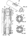
- FIG. 2A is a perspective view of a crossover tool according to one embodiment of the present disclosure.
- FIG. 2B illustrates the tool of FIG. 2A in cross-section coupled to tubing members.
- FIGS. 2C-2D are end-sections of the tool in FIG. 2A showing two alignment arrangements.
- FIG. 3A is a perspective view of a crossover tool having an alignment port according to another embodiment of the present disclosure.
- FIG. 3B illustrates the tool of FIG. 3A in cross-section coupled to tubing members.
- FIGS. 3C-3G are end-sections of the tool in FIG. 3A showing various arrangements of alignment.
- FIG. 4A is a cross-sectional view of a crossover tool having an alignment port and a disintegrating sleeve according to yet another embodiment of the present disclosure.
- FIGS. 4B-4C are end-sections of the tool in FIG. 4A showing two alignment arrangements.
- FIG. 4D is a perspective view of the tool in FIG. 4A without the external sleeve.
- FIG. 4E is a cross-sectional view of the crossover tool in FIG. 4A having the alignment port defined in the disintegrating sleeve.
- FIG. 4F is an end-section of the tool in FIG. 4E .
- FIG. 5A is a perspective view of a crossover tool having diversion ports configured to align in accordance with another embodiment of the present disclosure.
- FIG. 5B shows a portion of the tool in FIG. 5A shown in cross-section.
- FIG. 5C is an end-section of the tool in FIG. 5A .
- FIGS. 6A-6C illustrate a perspective view, a cross section, and an end section of another internal sleeve according to the present disclosure.
- a production assembly 100 illustrated in FIG. 1 has a production tubing string 120 run inside a well casing 110.
- a packer 112 attached to the tubing string 120 seals an upper annulus 116 from a lower annulus 118.
- a crossover tool 200 and a screen assembly 150 suspend from the tubing string 120 in the lower annulus 118.
- operators close off downhole communication from the tubing string 120 to the screen assembly 150 using a dropped ball, string manipulation, valve closure, or other technique known in the art. Uphole flow may or may not be closed off depending on the stage of the operation. With the downhole flow into the screen assembly 150 closed, the operators pump the slurry down the tubing string 120.
- the slurry passes through one or more internal ports (not shown) on an internal component of the tool 200 and then exists out one or more external ports 212 on an external component of the crossover tool 200. Exiting these ports 212, the slurry 140 enters the lower annulus 118 so the gravel in the exiting slurry 140 can pack around the screen assembly 150. When the operation is completed, the packed gravel can filter production fluid from the formation flowing through perforations 114 in the casing 110.
- crossover tool 200 is capable of aligning its internal and external ports downhole using an internal sleeve that is rotatable inside an external sleeve.
- a self-orienting crossover tool 200 includes an internal sleeve 220 rotatably positioned within an external sleeve 210.
- Both sleeves 210/220 define one or more external diversion ports 212/222 that are alignable with one another to divert slurry during operations as described above.
- diversion ports 212/222 are substantially rectangular and extend perpendicularly through sleeves 210 and 220.
- both diversion ports 212/222 are defined by slanted top and bottom ends so that they slope downwards from the interior bores of sleeve 210/220, as shown in FIG. 2B .
- both sleeves 210/220 preferably have the same number of ports 212/222.
- external ports 212 may be larger and are preferably positioned lower in external sleeve 210 so as to make an overall slanted passage though both sleeves 210/220 when aligned.
- external sleeve 210 positions within casing 110 so that its diversion ports 212 communicate with the annulus 118 formed between sleeve 210 and casing 110.
- internal sleeve 220 Being rotatably positioned within external sleeve 210, internal sleeve 220 has an upper end to which an upper internal tubing 230 couples with O-rings 223 and to which an upper intermediate tubing 240 also couples with a seal 224 and a bearing assembly 225.
- internal sleeve 220 has a lower end to which a lower internal tubing 235 couples with O-rings 223 and to which a lower intermediate tubing 245 couples with a seal 224 and a bearing assembly 225.
- the upper and lower intermediate tubings 240 and 245 remain substantially fixed, while seals 224 and bearing assemblies 225 on the upper and lower ends allow internal sleeve 220 to rotate within external sleeve 210.
- Reverse flow passages 221 may pass through the internal sleeve 220 to interconnect the annulus between upper tubings 230/240 with the annulus between lower tubings 235/245).
- crossover tool 200 is placed below a packer inside well casing.
- diversion ports 212/222 may have a misaligned orientation (as shown in FIG. 2C ) to increase the tools overall tensile strength while being manipulated downhole.
- operators pump slurry down the tubing. When the slurry meets the crossover tool 100, it is diverted through internal diversion ports 212, creating fluid friction in the annulus between sleeves 210/220 due to the misalignment of the ports 212/222. This fluid friction creates a thrust force that rotates internal sleeve 220 about its central axis 202 on its bearing assemblies 225.
- FIGS. 3A-3G illustrate another embodiment of a self-orienting crossover tool 300.
- Components of crossover tool 300 are substantially similar to those discussed in the embodiment of FIGS. 2A-2D so that like reference numbers are used for similar components.
- internal sleeve 220 defines a thrust or alignment port 310.
- This alignment port 310 communicates the interior of internal sleeve 220 with the inside of external sleeve 210.
- the alignment port 310 itself can have different configurations and can be straight, bent, or curved, as long as it is not coincident with the central rotational axis 202 of inner sleeve 220.
- FIGS. 3E-3F for example, alignment port 310 is substantially straight, whereas port 310 in FIG. 3G has a bent or angled configuration.
- diverted slurry pumped through crossover tool 300 causes internal sleeve 220 to rotate about is rotational axis 202 until its internal diversion ports 222 move into alignment with external diversion ports 212 (as shown in FIG. 3D ), and corrective forces bias inner sleeve 220 to remain in this aligned orientation.
- the pumped slurry diverts through alignment port 310, which causes internal sleeve 220 to rotate rapidly until this port 310 substantially aligns with one of the diversion ports 212 (as shown in FIGS. 3E-3F ).
- this port 310 tends to rotate internal sleeve 220 about its bearing assemblies 225 because alignment port 310 is eccentrically located ( i.e., passing transversely and tangentially) to internal sleeve's rotational axis 202. Furthermore, a build-up of pressure when this port 310 is not aligned with one of the diversion ports 222 can help produce thrust to facilitate rotation of internal sleeve 210. As with ports 212/222, thrust from alignment port 310 may be less when it is aligned with diversion port 212, further discouraging any rotation by inner sleeve 220 away from alignment. In this way, alignment port 310 facilitates proper alignment of diversion ports 212/222 and can reduce wear to the components. (Although the alignment port 310 is shown toward the downhole end of the inner sleeve 220, it may be arranged at the uphole end as long as it can communicate with the external port 212 when aligned therewith).
- FIGS. 4A-4D illustrate an embodiment of a self-orienting crossover tool 400, which again has similar components to previous embodiments so that like reference numbers are used for similar components.
- the crossover tool 400 has a temporary barrier 410.
- temporary barrier 410 is intended to increase flow through alignment port 310 and facilitate alignment between ports 212/222.
- temporary barrier 410 can be a cylindrically shaped sleeve positioned within the bore of internal sleeve 220 and covering diversion ports 222.
- Temporary barrier 410 can be composed of a material intended to disintegrate in a wellbore environment, such as a water soluble, synthetic polymer composition including a polyvinyl, alcohol plasticizer, and mineral filler.
- temporary barrier 410 can take the form of a plug, plate, sheath, or other form capable of temporarily obstructing fluid flow through at least one of the diversion ports 212.
- temporary barrier 410 may be mechanically displaced, dissolved, fragmented, or eroded in various embodiments, and downhole triggering devices or agents may also be employed to initiate removal of barrier 410.
- temporary barrier 410 substantially blocks flow of fluid through diversion port 222, thereby increasing pressure in the internal passage and increasing thrust through alignment port 310.
- temporary sleeve 410 is perforated as shown to allow at least some flow through the perforations.
- the increased thrust produced by alignment port 310 hastens rotation of internal sleeve 220 from an unaligned orientation ( FIG. 4B ) to an aligned orientation ( FIG. 4C ).
- the resulting thrust produced would be less than any thrust produced when sleeves 210/220 are not aligned. In this way, any further rotation of internal sleeve 210 would be discouraged.
- wellbore fluid and/or downhole conditions cause temporary barrier 410 to disintegrate so fluid can then flow directly through ports 212/222.
- the temporary sleeve 410 can define an alignment or thrust port 420.
- This port 420 can be provided in addition to or as an alternative to any alignment port in internal sleeve 220 as in previous embodiments.
- temporary barrier 410 substantially blocks flow of fluid through diversion port 222, thereby increasing pressure in the internal passage and the thrust or alignment port 420.
- the thrust produced by alignment port 420 rotates internal sleeve 220 until alignment port 420 aligns with diversion port 212 as shown in FIG. 4F .
- the resulting thrust produced in this aligned condition would be less than any thrust produced when sleeves 210/220 have different orientations so any further rotation of internal sleeve 210 would be discouraged.
- wellbore fluid and conditions cause temporary barrier 410 to disintegrate so fluid can then flow directly through ports 212, 222.
- FIGS. 5A-5C illustrate an embodiment of a crossover tool 500 in which thrust for alignment is achieved by diversion ports 522 on the internal sleeve 220.
- similar components between embodiments have the same reference numbers.
- Some elements in FIGS. 5A-5C such as bearing assemblies, seals, tubing, and the like, are not shown for simplicity; however, the internal and external sleeves 210/220 of the tool 500 can be used with such components as disclosed in other embodiments.
- internal sleeve 220 defines diversion ports 522 that are slanted or tangentially oriented as opposed to the orthogonal ports of previous embodiments.
- these slanted diversion ports 522 can have curvilinear sidewalls so that the ports 522 present a spiral cross-section.
- the slanted diversion ports 522 may have straight sidewalls or other shapes as long as they define a tangential exit direction for fluid flow from the ports 522.
- FIGS. 6A-6C illustrate a perspective view, a cross section, and an end section of another internal sleeve 600 according to the present disclosure.
- An external sleeve, bearing assemblies, seals, tubing, and the like are not shown for simplicity; however, the internal sleeve 600 can be used with such components as disclosed in other embodiments.
- the internal sleeve 600 rotatably positions inside an external sleeve and uses bearings assemblies and seals for coupling to internal tubing as described previously.
- the sleeve 600 has a cylindrical body defining an internal bore 604.
- Large side ports 606 are defined in the sides of the body 600 such that the body 600 forms two interconnecting stems 608 between upper and lower ends of the body 602. As shown, these ports 606 can have a square edge towards a first (upper end) of the body 602 and a slanted or angled edge towards a second (lower end) of the body 602.
- an external sleeve e.g., 210
- fluid exiting from ports 606 can rotate sleeve 606 to align ports 606 with external ports (e.g., 212) on the surrounding external sleeve (210). Being large, these ports 606 may experience less wear as the pumped slurry passes through.
- crossover tools may be fabricated from any suitable materials and according to any manufacturing techniques customary to oilfield production tools.
- features disclosed with reference to one embodiment may be combined with those disclosed with reference to other embodiments.
- crossover tools disclosed herein discuss the use of alignment ports and modified diversion ports individually, but additional embodiments may combine these features together.
- the embodiments discussed herein use two diversion ports on each of the sleeves. However, other embodiments may use on diversion port on each sleeve, or any same or different number of diversion ports on the two sleeves.
- alignment between ports refers to the relative orientation between the ports such that fluid can readily flow directly from one port through the other.
- the alignment may vary and may not need strict precision to achieve the purposes of the present disclosure.
Landscapes
- Life Sciences & Earth Sciences (AREA)
- Engineering & Computer Science (AREA)
- Geology (AREA)
- Mining & Mineral Resources (AREA)
- Physics & Mathematics (AREA)
- Environmental & Geological Engineering (AREA)
- Fluid Mechanics (AREA)
- General Life Sciences & Earth Sciences (AREA)
- Geochemistry & Mineralogy (AREA)
- Earth Drilling (AREA)
- Joints Allowing Movement (AREA)
- Quick-Acting Or Multi-Walled Pipe Joints (AREA)
Abstract
Description
- During oilfield production, granular materials in slurry form can be pumped into a wellbore to improve the well's production. For example, the slurry can be part of a gravel pack operation and can have solid granular or pelletized materials (e.g., gravel). Operators pump the gravel slurry down the tubing string. Downhole, a cross-over tool with exit ports diverts the slurry from the tubing string to the wellbore annulus so the gravel can be placed where desired. Once packed, the gravel can strain produced fluid and prevent fine material from entering the production string. In another example, operators can pump high-pressure fracture fluid downhole during a fracturing operation to form fractures in the formation. This fracturing fluid typically contains a proppant to maintain the newly formed fractures open. Again, a crossover tool on the production string can be used in the fracturing operation to direct the slurry of proppant into the wellbore annulus so it can interact with the formation.
- Flow of the slurry in these operations significantly wears the production assembly's components. For example, the slurry is viscous and can flow at a very high rate (e.g., above 10 bbls/min). As a result, the slurry's flow is highly erosive flow and can produce significant wear in the crossover tool even though the tool is typically made of 4140 steel or corrosion resistant alloys. The most severe damage occurs around the exit ports where the slurry exits the crossover tool and enters the inside of the production assembly. Typically, the crossover tool has inner and outer components that both have ports. As expected, any misalignment between such ports can aggravate wear as the slurry flows between them. If the wear is not managed properly, it can decrease the tool's tensile strength enough to cause failure under load and can also produce problems with sealing within the tool.
- According to a first aspect of the present invention, there is provided a downhole crossover tool, comprising: an external sleeve having a first axial bore and having an external port communicating with the first axial bore; and an internal sleeve having a second axial bore, the internal sleeve rotatably positioned within the first axial bore of the external sleeve and having an internal port, the internal port communicating with the second axial bore and being alignable with the external port of the external sleeve, wherein fluid flow communicated into the second axial bore tends to rotate the internal sleeve relative to the external sleeve at least until the internal port aligns with the external port.
- The internal sleeve may have a side port being alignable with the external port of the external sleeve, the side port being eccentrically located relative to a rotational axis of the internal sleeve.
- Fluid communicated into the second axial bore may pass through the side port and may tend to rotate the internal sleeve relative to the external sleeve at least until the side port aligns with the external port.
- The tool may further comprise a body positioned in the second axial bore and at least partially obstructing fluid flow through the internal port.
- The body may comprise a material intended to disintegrate in a wellbore environment.
- The body may comprise a cylindrical sleeve positioned within the second axial bore of the internal sleeve and at least partially covering the internal port.
- The cylindrical sleeve may have a plurality of perforations permitting restricted fluid flow therethrough.
- The cylindrical sleeve may define a side port being alignable with the external port on the external sleeve, the side port being eccentrically located relative to a rotational axis of the internal sleeve.
- Fluid communicated into the second axial bore may pass through the side port and may tend to rotate the internal sleeve relative to the external sleeve at least until the side port aligns with the external port.
- The internal sleeve may comprise first and second bearing assemblies positioned respectively between first and second ends of the internal sleeve and first and second tubing members.
- The internal port may define an exit direction substantially tangential to a rotational axis of the internal sleeve, and tangentially exiting fluid from the internal port may tend to rotate the internal sleeve relative to the external sleeve at least until the internal port aligns with the external port.
- According to another aspect of the present invention, there is provided a downhole crossover tool comprising: an external sleeve having a first axial bore and having an external port communicating with the first axial bore; and an internal sleeve having a second axial bore and rotatably positioned within the first axial bore of the external sleeve, the internal sleeve having an internal port communicating with the second axial bore and being alignable with the external port, the internal sleeve having a side port communicating with the second axial bore and being alignable with the external port, wherein fluid flow communicated into the second axial bore and through the side port tends to rotate the internal sleeve relative to the external sleeve at least until the side port aligns with the external port.
- The side port may be eccentrically located relative to a rotational axis of the internal sleeve.
- The tool may further comprise a body positioned in the second axial bore and at least partially obstructing fluid flow through the internal port.
- The body may comprise a material intended to disintegrate in a wellbore environment.
- The body may comprise a cylindrical sleeve positioned within the second axial bore of the internal sleeve and at least partially covering the internal port.
- The cylindrical sleeve may have a plurality of perforations permitting restricted fluid flow therethrough.
- According to a further aspect of the present invention, there is provided a downhole crossover tool comprising: an external sleeve having a first axial bore and having an external port communicating with the first axial bore; and an internal sleeve having a second axial bore, the internal sleeve rotatably positioned within the first axial bore of the external sleeve and having an internal port, the internal port communicating with the second axial bore and being alignable with the external port, the internal port defining an exit direction substantially tangential to a rotational axis of the internal sleeve, wherein tangentially exiting fluid flow communicated from the internal port tends to rotate the internal sleeve relative to the external sleeve at least until the internal port aligns with the external port.
- The internal port may define a curvilinear cross-section relative to the rotational axis of the internal sleeve.
- According to a further aspect of the present invention, there is provided a downhole crossover tool, comprising: external means for communicating fluid flow from a first axial bore through an external port; internal means disposed in the first axial bore for communicating fluid flow from a second axial bore to the first axial bore through an internal port; means for rotatably supporting the internal means within the first axial bore of the external means; and means for rotating the Internal means relative to the external means at least until the internal port aligns with the external port.
- The means for rotatably supporting may comprise means for rotatably supporting ends of the internal means within the external means.
- The means for rotating the internal means relative to the external means may comprise: fluid communicating means for communicating fluid flow eccentrically from the second axial bore to the first axial bore, the fluid communicating means being alignable with the external port of the external means.
- The tool may further comprise means for at least partially obstructing fluid flow through the internal port.
- The means for at least partially obstructing fluid may comprise means for disintegrating within a wellbore environment.
- The means for rotating the internal means relative to the external means may comprise means for producing tangentially exiting fluid flow from the internal port of the internal means.
- It should be understood that the features defined above in accordance with any aspect of the present invention or below in relation to any specific embodiment of the invention may be utilised, either alone or in combination, with any other defined feature, in any other aspect of the invention.
-
FIG. 1 illustrates a production assembly having a crossover tool. -
FIG. 2A is a perspective view of a crossover tool according to one embodiment of the present disclosure. -
FIG. 2B illustrates the tool ofFIG. 2A in cross-section coupled to tubing members. -
FIGS. 2C-2D are end-sections of the tool inFIG. 2A showing two alignment arrangements. -
FIG. 3A is a perspective view of a crossover tool having an alignment port according to another embodiment of the present disclosure. -
FIG. 3B illustrates the tool ofFIG. 3A in cross-section coupled to tubing members. -
FIGS. 3C-3G are end-sections of the tool inFIG. 3A showing various arrangements of alignment. -
FIG. 4A is a cross-sectional view of a crossover tool having an alignment port and a disintegrating sleeve according to yet another embodiment of the present disclosure. -
FIGS. 4B-4C are end-sections of the tool inFIG. 4A showing two alignment arrangements. -
FIG. 4D is a perspective view of the tool inFIG. 4A without the external sleeve. -
FIG. 4E is a cross-sectional view of the crossover tool inFIG. 4A having the alignment port defined in the disintegrating sleeve. -
FIG. 4F is an end-section of the tool inFIG. 4E . -
FIG. 5A is a perspective view of a crossover tool having diversion ports configured to align in accordance with another embodiment of the present disclosure. -
FIG. 5B shows a portion of the tool inFIG. 5A shown in cross-section. -
FIG. 5C is an end-section of the tool inFIG. 5A . -
FIGS. 6A-6C illustrate a perspective view, a cross section, and an end section of another internal sleeve according to the present disclosure. - A
production assembly 100 illustrated inFIG. 1 has aproduction tubing string 120 run inside awell casing 110. At a desired depth, apacker 112 attached to thetubing string 120 seals anupper annulus 116 from alower annulus 118. Acrossover tool 200 and ascreen assembly 150 suspend from thetubing string 120 in thelower annulus 118. To inject slurry in thelower annulus 118 for a gravel pack operation or the like, operators close off downhole communication from thetubing string 120 to thescreen assembly 150 using a dropped ball, string manipulation, valve closure, or other technique known in the art. Uphole flow may or may not be closed off depending on the stage of the operation. With the downhole flow into thescreen assembly 150 closed, the operators pump the slurry down thetubing string 120. When it reaches thecrossover tool 200, the slurry passes through one or more internal ports (not shown) on an internal component of thetool 200 and then exists out one or moreexternal ports 212 on an external component of thecrossover tool 200. Exiting theseports 212, theslurry 140 enters thelower annulus 118 so the gravel in the exitingslurry 140 can pack around thescreen assembly 150. When the operation is completed, the packed gravel can filter production fluid from the formation flowing throughperforations 114 in thecasing 110. - As discussed previously, any misalignment in the
crossover tool 200's internal ports (not shown) andexternal ports 212 can aggravate the wear produced by the flowing slurry. To overcome this, thecrossover tool 200 is capable of aligning its internal and external ports downhole using an internal sleeve that is rotatable inside an external sleeve. - As shown in
FIGS. 2A-2D , a self-orientingcrossover tool 200 includes aninternal sleeve 220 rotatably positioned within anexternal sleeve 210. Bothsleeves 210/220 define one or moreexternal diversion ports 212/222 that are alignable with one another to divert slurry during operations as described above. In general,diversion ports 212/222 are substantially rectangular and extend perpendicularly throughsleeves diversion ports 212/222 are defined by slanted top and bottom ends so that they slope downwards from the interior bores ofsleeve 210/220, as shown inFIG. 2B . In addition, bothsleeves 210/220 preferably have the same number ofports 212/222. However,external ports 212 may be larger and are preferably positioned lower inexternal sleeve 210 so as to make an overall slanted passage though bothsleeves 210/220 when aligned. - As best shown in
FIG. 2B ,external sleeve 210 positions withincasing 110 so that itsdiversion ports 212 communicate with theannulus 118 formed betweensleeve 210 andcasing 110. Being rotatably positioned withinexternal sleeve 210,internal sleeve 220 has an upper end to which an upperinternal tubing 230 couples with O-rings 223 and to which an upperintermediate tubing 240 also couples with aseal 224 and abearing assembly 225. Likewise,internal sleeve 220 has a lower end to which a lowerinternal tubing 235 couples with O-rings 223 and to which a lowerintermediate tubing 245 couples with aseal 224 and abearing assembly 225. The upper and lowerintermediate tubings seals 224 and bearingassemblies 225 on the upper and lower ends allowinternal sleeve 220 to rotate withinexternal sleeve 210. (Reverse flow passages 221 may pass through theinternal sleeve 220 to interconnect the annulus betweenupper tubings 230/240 with the annulus betweenlower tubings 235/245). - In use,
crossover tool 200 is placed below a packer inside well casing. Once positioned downhole,diversion ports 212/222 may have a misaligned orientation (as shown inFIG. 2C ) to increase the tools overall tensile strength while being manipulated downhole. In starting operations, operators pump slurry down the tubing. When the slurry meets thecrossover tool 100, it is diverted throughinternal diversion ports 212, creating fluid friction in the annulus betweensleeves 210/220 due to the misalignment of theports 212/222. This fluid friction creates a thrust force that rotatesinternal sleeve 220 about itscentral axis 202 on itsbearing assemblies 225. - After rotating a sufficient degree,
internal diversion ports 222 move into alignment with external diversion ports 212 (as shown inFIG. 2D ) to produce a passage for the slurry to the annulus surrounding thetool 200. Diverted slurry flows through this resulting passage, delivering particulate to the desired location. Onceports 212/222 achieve alignment, corrective forces biasinner sleeve 220 to keepports 212/222 aligned and to hinder any rotation byinner sleeve 220 away from alignment. In this way,ports 212/222 remain substantially aligned while pumped slurry passes through them to the surrounding annulus. This resulting alignment can, thereby, reduce wear to thecomponents 210/220. -
FIGS. 3A-3G illustrate another embodiment of a self-orientingcrossover tool 300. Components ofcrossover tool 300 are substantially similar to those discussed in the embodiment ofFIGS. 2A-2D so that like reference numbers are used for similar components. In the present embodiment,internal sleeve 220 defines a thrust oralignment port 310. Thisalignment port 310 communicates the interior ofinternal sleeve 220 with the inside ofexternal sleeve 210. Thealignment port 310 itself can have different configurations and can be straight, bent, or curved, as long as it is not coincident with the centralrotational axis 202 ofinner sleeve 220. InFIGS. 3E-3F , for example,alignment port 310 is substantially straight, whereasport 310 inFIG. 3G has a bent or angled configuration. - As before, diverted slurry pumped through
crossover tool 300 causesinternal sleeve 220 to rotate about isrotational axis 202 until itsinternal diversion ports 222 move into alignment with external diversion ports 212 (as shown inFIG. 3D ), and corrective forces biasinner sleeve 220 to remain in this aligned orientation. In addition to the alignment caused byports 212/222 themselves, the pumped slurry diverts throughalignment port 310, which causesinternal sleeve 220 to rotate rapidly until thisport 310 substantially aligns with one of the diversion ports 212 (as shown inFIGS. 3E-3F ). - In particular, flow through this
port 310 tends to rotateinternal sleeve 220 about itsbearing assemblies 225 becausealignment port 310 is eccentrically located (i.e., passing transversely and tangentially) to internal sleeve'srotational axis 202. Furthermore, a build-up of pressure when thisport 310 is not aligned with one of thediversion ports 222 can help produce thrust to facilitate rotation ofinternal sleeve 210. As withports 212/222, thrust fromalignment port 310 may be less when it is aligned withdiversion port 212, further discouraging any rotation byinner sleeve 220 away from alignment. In this way,alignment port 310 facilitates proper alignment ofdiversion ports 212/222 and can reduce wear to the components. (Although thealignment port 310 is shown toward the downhole end of theinner sleeve 220, it may be arranged at the uphole end as long as it can communicate with theexternal port 212 when aligned therewith). -
FIGS. 4A-4D illustrate an embodiment of a self-orientingcrossover tool 400, which again has similar components to previous embodiments so that like reference numbers are used for similar components. In addition to an alignment or thrustport 310 similar to that discussed previously, thecrossover tool 400 has atemporary barrier 410. For its part,temporary barrier 410 is intended to increase flow throughalignment port 310 and facilitate alignment betweenports 212/222. - As shown in
FIGS. 4A and4D ,temporary barrier 410 can be a cylindrically shaped sleeve positioned within the bore ofinternal sleeve 220 and coveringdiversion ports 222.Temporary barrier 410 can be composed of a material intended to disintegrate in a wellbore environment, such as a water soluble, synthetic polymer composition including a polyvinyl, alcohol plasticizer, and mineral filler. Rather than a cylindrically shaped sleeve,temporary barrier 410 can take the form of a plug, plate, sheath, or other form capable of temporarily obstructing fluid flow through at least one of thediversion ports 212. Finally,temporary barrier 410 may be mechanically displaced, dissolved, fragmented, or eroded in various embodiments, and downhole triggering devices or agents may also be employed to initiate removal ofbarrier 410. - In use,
temporary barrier 410 substantially blocks flow of fluid throughdiversion port 222, thereby increasing pressure in the internal passage and increasing thrust throughalignment port 310. Preferably,temporary sleeve 410 is perforated as shown to allow at least some flow through the perforations. The increased thrust produced byalignment port 310 hastens rotation ofinternal sleeve 220 from an unaligned orientation (FIG. 4B ) to an aligned orientation (FIG. 4C ). Oncealignment port 310 substantially aligns with diversion port 212 (FIG. 4C ), the resulting thrust produced would be less than any thrust produced whensleeves 210/220 are not aligned. In this way, any further rotation ofinternal sleeve 210 would be discouraged. Eventually, wellbore fluid and/or downhole conditions causetemporary barrier 410 to disintegrate so fluid can then flow directly throughports 212/222. - In an alternative shown in
FIG. 4E , thetemporary sleeve 410 can define an alignment or thrustport 420. Thisport 420 can be provided in addition to or as an alternative to any alignment port ininternal sleeve 220 as in previous embodiments. Again,temporary barrier 410 substantially blocks flow of fluid throughdiversion port 222, thereby increasing pressure in the internal passage and the thrust oralignment port 420. Eventually, the thrust produced byalignment port 420 rotatesinternal sleeve 220 untilalignment port 420 aligns withdiversion port 212 as shown inFIG. 4F . The resulting thrust produced in this aligned condition would be less than any thrust produced whensleeves 210/220 have different orientations so any further rotation ofinternal sleeve 210 would be discouraged. Eventually, wellbore fluid and conditions causetemporary barrier 410 to disintegrate so fluid can then flow directly throughports -
Figures 5A-5C illustrate an embodiment of acrossover tool 500 in which thrust for alignment is achieved bydiversion ports 522 on theinternal sleeve 220. Again, similar components between embodiments have the same reference numbers. Some elements inFIGS. 5A-5C , such as bearing assemblies, seals, tubing, and the like, are not shown for simplicity; however, the internal andexternal sleeves 210/220 of thetool 500 can be used with such components as disclosed in other embodiments. As best shown in the end-section ofFIG. 5C ,internal sleeve 220 definesdiversion ports 522 that are slanted or tangentially oriented as opposed to the orthogonal ports of previous embodiments. As shown, these slanteddiversion ports 522 can have curvilinear sidewalls so that theports 522 present a spiral cross-section. However, the slanteddiversion ports 522 may have straight sidewalls or other shapes as long as they define a tangential exit direction for fluid flow from theports 522. - When diverted slurry flows through these
diversion ports 522, it exits in a tangential direction, which causesinternal sleeve 220 to rotate relative toexternal sleeve 210 untildiversion ports 522 substantially align withexternal ports 212 as shown inFIG. 5C . In this aligned condition, corrective forces will substantially prevent the tendency ofinternal sleeve 220 to rotate out of alignment, because the thrust produced bydiversion ports 522 when substantially aligned withdiversion ports 212 would be less than thrust produced when thesleeves 210/220 are not aligned. -
FIGS. 6A-6C illustrate a perspective view, a cross section, and an end section of anotherinternal sleeve 600 according to the present disclosure. An external sleeve, bearing assemblies, seals, tubing, and the like are not shown for simplicity; however, theinternal sleeve 600 can be used with such components as disclosed in other embodiments. For example, theinternal sleeve 600 rotatably positions inside an external sleeve and uses bearings assemblies and seals for coupling to internal tubing as described previously. - In this embodiment, the
sleeve 600 has a cylindrical body defining aninternal bore 604.Large side ports 606 are defined in the sides of thebody 600 such that thebody 600 forms two interconnecting stems 608 between upper and lower ends of thebody 602. As shown, theseports 606 can have a square edge towards a first (upper end) of thebody 602 and a slanted or angled edge towards a second (lower end) of thebody 602. When positioned in an external sleeve (e.g., 210), fluid exiting fromports 606 can rotatesleeve 606 to alignports 606 with external ports (e.g., 212) on the surrounding external sleeve (210). Being large, theseports 606 may experience less wear as the pumped slurry passes through. - The foregoing description of preferred and other embodiments is not intended to limit or restrict the scope or applicability of the inventive concepts conceived of by the Applicants. In general, for example, components of the disclosed crossover tools may be fabricated from any suitable materials and according to any manufacturing techniques customary to oilfield production tools. In addition, features disclosed with reference to one embodiment may be combined with those disclosed with reference to other embodiments. For example, crossover tools disclosed herein discuss the use of alignment ports and modified diversion ports individually, but additional embodiments may combine these features together. In addition, the embodiments discussed herein use two diversion ports on each of the sleeves. However, other embodiments may use on diversion port on each sleeve, or any same or different number of diversion ports on the two sleeves.
- As used herein, alignment between ports (such as
port 212 withport 222,port 310 withport 222, etc.) refers to the relative orientation between the ports such that fluid can readily flow directly from one port through the other. The alignment may vary and may not need strict precision to achieve the purposes of the present disclosure. - In exchange for disclosing the inventive concepts contained herein, the Applicants desire all patent rights afforded by the appended claims. Therefore, it is intended that the appended claims include all modifications and alterations to the full extent that they come within the scope of the following claims or the equivalents thereof.
Claims (15)
- A downhole crossover tool, comprising:external means for communicating fluid flow from a first axial bore through an external port;internal means disposed in the first axial bore for communicating fluid flow from a second axial bore to the first axial bore through an internal port;means for rotatably supporting the internal means within the first axial bore of the external means; andmeans for rotating the internal means relative to the external means at least until the internal port aligns with the external port.
- The tool of claim 1, wherein:the external means comprises an external sleeve having the first axial bore and having the external port communicating with the first axial bore; andthe internal means comprises an internal sleeve having the second axial bore, the internal sleeve rotatably positioned within the first axial bore of the external sleeve and having the internal port, the internal port communicating with the second axial bore and being alignable with the external port of the external sleeve,wherein fluid flow communicated into the second axial bore tends to rotate the internal sleeve relative to the external sleeve at least until the internal port aligns with the external port.
- The tool of claim 1 or 2, wherein the internal sleeve has a side port communicating with the second axial bore and being alignable with the external port, and wherein fluid flow communicated into the second axial bore and through the side port tends to rotate the internal sleeve relative to the external sleeve at least until the side port aligns with the external port.
- The tool of claim 1, 2 or 3, further comprising means for at least partially obstructing fluid flow through the internal port.
- The tool of claim 4, wherein the means for at least partially obstructing fluid comprise means for disintegrating within a wellbore environment.
- The tool of claim 4, wherein the means for at least partially obstructing fluid flow through the internal port comprises a body positioned in the second axial bore.
- The tool of claim 6, wherein the body comprises a material intended to disintegrate in a wellbore environment.
- The tool of claim 6, wherein the body comprises a cylindrical sleeve positioned within the second axial bore and at least partially covering the internal port, and wherein optionally the cylindrical sleeve has a plurality of perforations permitting restricted fluid flow therethrough.
- The tool of claim 8, wherein the cylindrical sleeve defines a side port being alignable with the external port on the external means, the side port being eccentrically located relative to a rotational axis of the internal means, and wherein optionally fluid communicated into the second axial bore passes through the side port and tends to rotate the internal sleeve relative to the external sleeve at least until the side port aligns with the external port.
- The tool of any preceding claim, wherein the means for rotating the internal means relative to the external means comprises means for producing tangentially exiting fluid flow from the internal port of the internal means.
- The tool of claim 10, wherein the internal port defines an exit direction substantially tangential to a rotational axis of the internal means, wherein tangentially exiting fluid flow communicated from the internal port tends to rotate the internal means relative to the external means at least until the internal port aligns with the external port.
- The tool of claim 11, wherein the internal port defines a curvilinear cross-section relative to the rotational axis of the internal means.
- The tool of any preceding claim, wherein the means for rotatably supporting comprises means for rotatably supporting ends of the internal means within the external means.
- The tool of any preceding claim, wherein the internal means comprises first and second bearing assemblies positioned respectively between first and second ends of the internal means and first and second tubing members.
- The tool of any preceding claim, wherein the means for rotating the internal means relative to the external means comprises: fluid communicating means for communicating fluid flow eccentrically from the second axial bore to the first axial bore, the fluid communicating means being alignable with the external port of the external means.
Applications Claiming Priority (1)
| Application Number | Priority Date | Filing Date | Title |
|---|---|---|---|
| US12/862,833 US8695709B2 (en) | 2010-08-25 | 2010-08-25 | Self-orienting crossover tool |
Publications (3)
| Publication Number | Publication Date |
|---|---|
| EP2423431A2 true EP2423431A2 (en) | 2012-02-29 |
| EP2423431A3 EP2423431A3 (en) | 2014-04-16 |
| EP2423431B1 EP2423431B1 (en) | 2015-08-05 |
Family
ID=45000035
Family Applications (1)
| Application Number | Title | Priority Date | Filing Date |
|---|---|---|---|
| EP11250738.9A Not-in-force EP2423431B1 (en) | 2010-08-25 | 2011-08-24 | Self-orienting croosover tool |
Country Status (4)
| Country | Link |
|---|---|
| US (1) | US8695709B2 (en) |
| EP (1) | EP2423431B1 (en) |
| AU (1) | AU2011205112B2 (en) |
| CA (1) | CA2747277C (en) |
Cited By (2)
| Publication number | Priority date | Publication date | Assignee | Title |
|---|---|---|---|---|
| WO2014075160A1 (en) * | 2012-11-13 | 2014-05-22 | Andrew Wright | Automatic tubing drain |
| US9677383B2 (en) | 2013-02-28 | 2017-06-13 | Weatherford Technology Holdings, Llc | Erosion ports for shunt tubes |
Families Citing this family (13)
| Publication number | Priority date | Publication date | Assignee | Title |
|---|---|---|---|---|
| US8887816B2 (en) * | 2011-07-29 | 2014-11-18 | Halliburton Energy Services, Inc. | Polymer compositions for use in downhole tools and components thereof |
| US9004185B2 (en) * | 2012-01-05 | 2015-04-14 | Baker Hughes Incorporated | Downhole plug drop tool |
| US10100601B2 (en) | 2014-12-16 | 2018-10-16 | Baker Hughes, A Ge Company, Llc | Downhole assembly having isolation tool and method |
| SG11201901467QA (en) | 2016-09-23 | 2019-03-28 | Halliburton Energy Services Inc | Systems and methods for controlling fluid flow in a wellbore using a switchable downhole crossover tool with rotatable sleeve |
| US11313202B2 (en) | 2016-09-23 | 2022-04-26 | Halliburton Energy Services, Inc. | Systems and methods for controlling fluid flow in a wellbore using a switchable downhole crossover tool |
| GB2567113B (en) * | 2016-09-23 | 2021-08-04 | Halliburton Energy Services Inc | Switchable crossover tool with hydraulic transmission |
| US10648286B2 (en) | 2016-09-23 | 2020-05-12 | Halliburton Energy Services, Inc. | Methods for cementing a well using a switchable crossover device |
| CA3033163A1 (en) * | 2016-09-23 | 2018-03-29 | Halliburton Energy Services, Inc. | Switchable crossover tool with rotatable chamber |
| US10428623B2 (en) | 2016-11-01 | 2019-10-01 | Baker Hughes, A Ge Company, Llc | Ball dropping system and method |
| US12215571B2 (en) | 2021-07-02 | 2025-02-04 | Halliburton Energy Services, Inc. | Pressure indication alignment using an orientation port and orientation slot |
| US12006796B2 (en) | 2021-07-02 | 2024-06-11 | Halliburton Energy Services, Inc. | Pressure indication alignment using an orientation port and two radial orientation slots |
| US12000250B2 (en) * | 2021-07-02 | 2024-06-04 | Halliburton Energy Services, Inc. | Pressure indication alignment using an orientation port and an orientation slot in a weighted swivel |
| US12516589B2 (en) * | 2023-09-21 | 2026-01-06 | Halliburton Energy Services, Inc. | Downhole flow control valve for well systems |
Family Cites Families (18)
| Publication number | Priority date | Publication date | Assignee | Title |
|---|---|---|---|---|
| US3993130A (en) | 1975-05-14 | 1976-11-23 | Texaco Inc. | Method and apparatus for controlling the injection profile of a borehole |
| US4044832A (en) | 1976-08-27 | 1977-08-30 | Baker International Corporation | Concentric gravel pack with crossover tool and method of gravel packing |
| US4262693A (en) * | 1979-07-02 | 1981-04-21 | Bernhardt & Frederick Co., Inc. | Kelly valve |
| US4270608A (en) * | 1979-12-27 | 1981-06-02 | Halliburton Company | Method and apparatus for gravel packing multiple zones |
| US4296807A (en) | 1979-12-27 | 1981-10-27 | Halliburton Company | Crossover tool |
| US4570714A (en) * | 1983-12-22 | 1986-02-18 | Geo Vann, Inc. | Gravel pack assembly |
| US4858691A (en) * | 1988-06-13 | 1989-08-22 | Baker Hughes Incorporated | Gravel packing apparatus and method |
| US5636691A (en) | 1995-09-18 | 1997-06-10 | Halliburton Energy Services, Inc. | Abrasive slurry delivery apparatus and methods of using same |
| US6488082B2 (en) | 2001-01-23 | 2002-12-03 | Halliburton Energy Services, Inc. | Remotely operated multi-zone packing system |
| US6702020B2 (en) | 2002-04-11 | 2004-03-09 | Baker Hughes Incorporated | Crossover Tool |
| WO2004013461A1 (en) | 2002-08-01 | 2004-02-12 | Baker Hughes Incorporated | Gravel pack crossover tool with check valve in the evacuation port |
| US6978840B2 (en) | 2003-02-05 | 2005-12-27 | Halliburton Energy Services, Inc. | Well screen assembly and system with controllable variable flow area and method of using same for oil well fluid production |
| US6981551B2 (en) | 2003-07-07 | 2006-01-03 | Bj Services Company | Cross-over tool return port cover |
| US7128151B2 (en) | 2003-11-17 | 2006-10-31 | Baker Hughes Incorporated | Gravel pack crossover tool with single position multi-function capability |
| US7096946B2 (en) | 2003-12-30 | 2006-08-29 | Baker Hughes Incorporated | Rotating blast liner |
| US20090084553A1 (en) | 2004-12-14 | 2009-04-02 | Schlumberger Technology Corporation | Sliding sleeve valve assembly with sand screen |
| WO2007005765A1 (en) | 2005-06-30 | 2007-01-11 | M-I L.L.C. | Downhole multi-action jetting tool |
| US7762324B2 (en) | 2007-12-04 | 2010-07-27 | Baker Hughes Incorporated | Bypass crossover sub selector for multi-zone fracturing processes |
-
2010
- 2010-08-25 US US12/862,833 patent/US8695709B2/en not_active Expired - Fee Related
-
2011
- 2011-07-26 CA CA2747277A patent/CA2747277C/en not_active Expired - Fee Related
- 2011-08-02 AU AU2011205112A patent/AU2011205112B2/en not_active Ceased
- 2011-08-24 EP EP11250738.9A patent/EP2423431B1/en not_active Not-in-force
Non-Patent Citations (1)
| Title |
|---|
| None |
Cited By (3)
| Publication number | Priority date | Publication date | Assignee | Title |
|---|---|---|---|---|
| WO2014075160A1 (en) * | 2012-11-13 | 2014-05-22 | Andrew Wright | Automatic tubing drain |
| US10180040B2 (en) | 2012-11-13 | 2019-01-15 | Gadu Inc. | Automatic tubing drain |
| US9677383B2 (en) | 2013-02-28 | 2017-06-13 | Weatherford Technology Holdings, Llc | Erosion ports for shunt tubes |
Also Published As
| Publication number | Publication date |
|---|---|
| US8695709B2 (en) | 2014-04-15 |
| CA2747277A1 (en) | 2012-02-25 |
| US20120048562A1 (en) | 2012-03-01 |
| AU2011205112B2 (en) | 2013-11-28 |
| AU2011205112A1 (en) | 2012-03-15 |
| EP2423431A3 (en) | 2014-04-16 |
| CA2747277C (en) | 2015-01-06 |
| EP2423431B1 (en) | 2015-08-05 |
Similar Documents
| Publication | Publication Date | Title |
|---|---|---|
| US8695709B2 (en) | Self-orienting crossover tool | |
| CA2752690C (en) | Managed pressure conduit assembly systems and methods for extending or using a passageway through subterranean strata | |
| CA3038803C (en) | Frac and gravel packing system having return path and method | |
| AU2006216550B2 (en) | Multiple port cross-over design for frac pack erosion mititgation | |
| EP2715040B1 (en) | Variably configurable wellbore junction assembly | |
| US20090321076A1 (en) | Completion Method with Telescoping Perforation & Fracturing Tool | |
| JPH10510892A (en) | Method and apparatus for perforating using high-pressure liquid with low solids content | |
| CA3124339C (en) | Downhole disconnect tool | |
| US8011433B2 (en) | Bidirectional gravel packing in subterranean wells | |
| US20050098351A1 (en) | Downhole valve device | |
| AU2012381051A1 (en) | Erosion reduction in subterranean wells | |
| US5924487A (en) | Proppant slurry screen apparatus and methods of using same | |
| AU2011203566C1 (en) | Systems and methods for using a passageway through a subterranean strata | |
| US20240175337A1 (en) | Fluidic diode operated autofill valve | |
| CA2752322A1 (en) | Systems and methods for using rock debris to inhibit the initiation or propagation of fractures within a passageway through subterranean strata | |
| CN114837628A (en) | Flow control screen for oil well |
Legal Events
| Date | Code | Title | Description |
|---|---|---|---|
| 17P | Request for examination filed |
Effective date: 20110905 |
|
| AK | Designated contracting states |
Kind code of ref document: A2 Designated state(s): AL AT BE BG CH CY CZ DE DK EE ES FI FR GB GR HR HU IE IS IT LI LT LU LV MC MK MT NL NO PL PT RO RS SE SI SK SM TR |
|
| AX | Request for extension of the european patent |
Extension state: BA ME |
|
| PUAI | Public reference made under article 153(3) epc to a published international application that has entered the european phase |
Free format text: ORIGINAL CODE: 0009012 |
|
| PUAL | Search report despatched |
Free format text: ORIGINAL CODE: 0009013 |
|
| AK | Designated contracting states |
Kind code of ref document: A3 Designated state(s): AL AT BE BG CH CY CZ DE DK EE ES FI FR GB GR HR HU IE IS IT LI LT LU LV MC MK MT NL NO PL PT RO RS SE SI SK SM TR |
|
| AX | Request for extension of the european patent |
Extension state: BA ME |
|
| RIC1 | Information provided on ipc code assigned before grant |
Ipc: E21B 43/04 20060101AFI20140310BHEP Ipc: E21B 34/00 20060101ALN20140310BHEP |
|
| RAP1 | Party data changed (applicant data changed or rights of an application transferred) |
Owner name: WEATHERFORD/LAMB, INC. |
|
| RIC1 | Information provided on ipc code assigned before grant |
Ipc: E21B 43/04 20060101AFI20141201BHEP Ipc: E21B 34/00 20060101ALN20141201BHEP |
|
| GRAJ | Information related to disapproval of communication of intention to grant by the applicant or resumption of examination proceedings by the epo deleted |
Free format text: ORIGINAL CODE: EPIDOSDIGR1 |
|
| GRAP | Despatch of communication of intention to grant a patent |
Free format text: ORIGINAL CODE: EPIDOSNIGR1 |
|
| GRAP | Despatch of communication of intention to grant a patent |
Free format text: ORIGINAL CODE: EPIDOSNIGR1 |
|
| INTG | Intention to grant announced |
Effective date: 20150220 |
|
| RAP1 | Party data changed (applicant data changed or rights of an application transferred) |
Owner name: WEATHERFORD TECHNOLOGY HOLDINGS, LLC |
|
| GRAS | Grant fee paid |
Free format text: ORIGINAL CODE: EPIDOSNIGR3 |
|
| GRAA | (expected) grant |
Free format text: ORIGINAL CODE: 0009210 |
|
| AK | Designated contracting states |
Kind code of ref document: B1 Designated state(s): AL AT BE BG CH CY CZ DE DK EE ES FI FR GB GR HR HU IE IS IT LI LT LU LV MC MK MT NL NO PL PT RO RS SE SI SK SM TR |
|
| REG | Reference to a national code |
Ref country code: GB Ref legal event code: FG4D |
|
| REG | Reference to a national code |
Ref country code: CH Ref legal event code: EP |
|
| REG | Reference to a national code |
Ref country code: AT Ref legal event code: REF Ref document number: 740832 Country of ref document: AT Kind code of ref document: T Effective date: 20150815 |
|
| REG | Reference to a national code |
Ref country code: IE Ref legal event code: FG4D |
|
| REG | Reference to a national code |
Ref country code: DE Ref legal event code: R096 Ref document number: 602011018421 Country of ref document: DE |
|
| REG | Reference to a national code |
Ref country code: AT Ref legal event code: MK05 Ref document number: 740832 Country of ref document: AT Kind code of ref document: T Effective date: 20150805 |
|
| REG | Reference to a national code |
Ref country code: NO Ref legal event code: T2 Effective date: 20150805 Ref country code: LT Ref legal event code: MG4D |
|
| REG | Reference to a national code |
Ref country code: NL Ref legal event code: FP |
|
| PG25 | Lapsed in a contracting state [announced via postgrant information from national office to epo] |
Ref country code: LV Free format text: LAPSE BECAUSE OF FAILURE TO SUBMIT A TRANSLATION OF THE DESCRIPTION OR TO PAY THE FEE WITHIN THE PRESCRIBED TIME-LIMIT Effective date: 20150805 Ref country code: LT Free format text: LAPSE BECAUSE OF FAILURE TO SUBMIT A TRANSLATION OF THE DESCRIPTION OR TO PAY THE FEE WITHIN THE PRESCRIBED TIME-LIMIT Effective date: 20150805 Ref country code: FI Free format text: LAPSE BECAUSE OF FAILURE TO SUBMIT A TRANSLATION OF THE DESCRIPTION OR TO PAY THE FEE WITHIN THE PRESCRIBED TIME-LIMIT Effective date: 20150805 Ref country code: GR Free format text: LAPSE BECAUSE OF FAILURE TO SUBMIT A TRANSLATION OF THE DESCRIPTION OR TO PAY THE FEE WITHIN THE PRESCRIBED TIME-LIMIT Effective date: 20151106 |
|
| PG25 | Lapsed in a contracting state [announced via postgrant information from national office to epo] |
Ref country code: RS Free format text: LAPSE BECAUSE OF FAILURE TO SUBMIT A TRANSLATION OF THE DESCRIPTION OR TO PAY THE FEE WITHIN THE PRESCRIBED TIME-LIMIT Effective date: 20150805 Ref country code: HR Free format text: LAPSE BECAUSE OF FAILURE TO SUBMIT A TRANSLATION OF THE DESCRIPTION OR TO PAY THE FEE WITHIN THE PRESCRIBED TIME-LIMIT Effective date: 20150805 Ref country code: ES Free format text: LAPSE BECAUSE OF FAILURE TO SUBMIT A TRANSLATION OF THE DESCRIPTION OR TO PAY THE FEE WITHIN THE PRESCRIBED TIME-LIMIT Effective date: 20150805 Ref country code: PT Free format text: LAPSE BECAUSE OF FAILURE TO SUBMIT A TRANSLATION OF THE DESCRIPTION OR TO PAY THE FEE WITHIN THE PRESCRIBED TIME-LIMIT Effective date: 20151207 Ref country code: SE Free format text: LAPSE BECAUSE OF FAILURE TO SUBMIT A TRANSLATION OF THE DESCRIPTION OR TO PAY THE FEE WITHIN THE PRESCRIBED TIME-LIMIT Effective date: 20150805 Ref country code: PL Free format text: LAPSE BECAUSE OF FAILURE TO SUBMIT A TRANSLATION OF THE DESCRIPTION OR TO PAY THE FEE WITHIN THE PRESCRIBED TIME-LIMIT Effective date: 20150805 Ref country code: IS Free format text: LAPSE BECAUSE OF FAILURE TO SUBMIT A TRANSLATION OF THE DESCRIPTION OR TO PAY THE FEE WITHIN THE PRESCRIBED TIME-LIMIT Effective date: 20151205 Ref country code: AT Free format text: LAPSE BECAUSE OF FAILURE TO SUBMIT A TRANSLATION OF THE DESCRIPTION OR TO PAY THE FEE WITHIN THE PRESCRIBED TIME-LIMIT Effective date: 20150805 |
|
| REG | Reference to a national code |
Ref country code: CH Ref legal event code: PL |
|
| PG25 | Lapsed in a contracting state [announced via postgrant information from national office to epo] |
Ref country code: EE Free format text: LAPSE BECAUSE OF FAILURE TO SUBMIT A TRANSLATION OF THE DESCRIPTION OR TO PAY THE FEE WITHIN THE PRESCRIBED TIME-LIMIT Effective date: 20150805 Ref country code: IT Free format text: LAPSE BECAUSE OF FAILURE TO SUBMIT A TRANSLATION OF THE DESCRIPTION OR TO PAY THE FEE WITHIN THE PRESCRIBED TIME-LIMIT Effective date: 20150805 Ref country code: SK Free format text: LAPSE BECAUSE OF FAILURE TO SUBMIT A TRANSLATION OF THE DESCRIPTION OR TO PAY THE FEE WITHIN THE PRESCRIBED TIME-LIMIT Effective date: 20150805 Ref country code: LI Free format text: LAPSE BECAUSE OF NON-PAYMENT OF DUE FEES Effective date: 20150831 Ref country code: CZ Free format text: LAPSE BECAUSE OF FAILURE TO SUBMIT A TRANSLATION OF THE DESCRIPTION OR TO PAY THE FEE WITHIN THE PRESCRIBED TIME-LIMIT Effective date: 20150805 Ref country code: CH Free format text: LAPSE BECAUSE OF NON-PAYMENT OF DUE FEES Effective date: 20150831 Ref country code: DK Free format text: LAPSE BECAUSE OF FAILURE TO SUBMIT A TRANSLATION OF THE DESCRIPTION OR TO PAY THE FEE WITHIN THE PRESCRIBED TIME-LIMIT Effective date: 20150805 |
|
| REG | Reference to a national code |
Ref country code: DE Ref legal event code: R097 Ref document number: 602011018421 Country of ref document: DE |
|
| PG25 | Lapsed in a contracting state [announced via postgrant information from national office to epo] |
Ref country code: RO Free format text: LAPSE BECAUSE OF FAILURE TO SUBMIT A TRANSLATION OF THE DESCRIPTION OR TO PAY THE FEE WITHIN THE PRESCRIBED TIME-LIMIT Effective date: 20150805 Ref country code: MC Free format text: LAPSE BECAUSE OF FAILURE TO SUBMIT A TRANSLATION OF THE DESCRIPTION OR TO PAY THE FEE WITHIN THE PRESCRIBED TIME-LIMIT Effective date: 20150805 |
|
| REG | Reference to a national code |
Ref country code: IE Ref legal event code: MM4A |
|
| PLBE | No opposition filed within time limit |
Free format text: ORIGINAL CODE: 0009261 |
|
| STAA | Information on the status of an ep patent application or granted ep patent |
Free format text: STATUS: NO OPPOSITION FILED WITHIN TIME LIMIT |
|
| REG | Reference to a national code |
Ref country code: FR Ref legal event code: PLFP Year of fee payment: 6 |
|
| 26N | No opposition filed |
Effective date: 20160509 |
|
| PG25 | Lapsed in a contracting state [announced via postgrant information from national office to epo] |
Ref country code: IE Free format text: LAPSE BECAUSE OF NON-PAYMENT OF DUE FEES Effective date: 20150824 |
|
| PG25 | Lapsed in a contracting state [announced via postgrant information from national office to epo] |
Ref country code: SI Free format text: LAPSE BECAUSE OF FAILURE TO SUBMIT A TRANSLATION OF THE DESCRIPTION OR TO PAY THE FEE WITHIN THE PRESCRIBED TIME-LIMIT Effective date: 20150805 |
|
| PG25 | Lapsed in a contracting state [announced via postgrant information from national office to epo] |
Ref country code: MT Free format text: LAPSE BECAUSE OF FAILURE TO SUBMIT A TRANSLATION OF THE DESCRIPTION OR TO PAY THE FEE WITHIN THE PRESCRIBED TIME-LIMIT Effective date: 20150805 |
|
| PG25 | Lapsed in a contracting state [announced via postgrant information from national office to epo] |
Ref country code: BG Free format text: LAPSE BECAUSE OF FAILURE TO SUBMIT A TRANSLATION OF THE DESCRIPTION OR TO PAY THE FEE WITHIN THE PRESCRIBED TIME-LIMIT Effective date: 20150805 Ref country code: SM Free format text: LAPSE BECAUSE OF FAILURE TO SUBMIT A TRANSLATION OF THE DESCRIPTION OR TO PAY THE FEE WITHIN THE PRESCRIBED TIME-LIMIT Effective date: 20150805 Ref country code: HU Free format text: LAPSE BECAUSE OF FAILURE TO SUBMIT A TRANSLATION OF THE DESCRIPTION OR TO PAY THE FEE WITHIN THE PRESCRIBED TIME-LIMIT; INVALID AB INITIO Effective date: 20110824 |
|
| PG25 | Lapsed in a contracting state [announced via postgrant information from national office to epo] |
Ref country code: CY Free format text: LAPSE BECAUSE OF FAILURE TO SUBMIT A TRANSLATION OF THE DESCRIPTION OR TO PAY THE FEE WITHIN THE PRESCRIBED TIME-LIMIT Effective date: 20150805 |
|
| REG | Reference to a national code |
Ref country code: FR Ref legal event code: PLFP Year of fee payment: 7 |
|
| PG25 | Lapsed in a contracting state [announced via postgrant information from national office to epo] |
Ref country code: BE Free format text: LAPSE BECAUSE OF NON-PAYMENT OF DUE FEES Effective date: 20150831 |
|
| PG25 | Lapsed in a contracting state [announced via postgrant information from national office to epo] |
Ref country code: TR Free format text: LAPSE BECAUSE OF FAILURE TO SUBMIT A TRANSLATION OF THE DESCRIPTION OR TO PAY THE FEE WITHIN THE PRESCRIBED TIME-LIMIT Effective date: 20150805 |
|
| PG25 | Lapsed in a contracting state [announced via postgrant information from national office to epo] |
Ref country code: LU Free format text: LAPSE BECAUSE OF NON-PAYMENT OF DUE FEES Effective date: 20150824 |
|
| PG25 | Lapsed in a contracting state [announced via postgrant information from national office to epo] |
Ref country code: MK Free format text: LAPSE BECAUSE OF FAILURE TO SUBMIT A TRANSLATION OF THE DESCRIPTION OR TO PAY THE FEE WITHIN THE PRESCRIBED TIME-LIMIT Effective date: 20150805 |
|
| REG | Reference to a national code |
Ref country code: FR Ref legal event code: PLFP Year of fee payment: 8 |
|
| PG25 | Lapsed in a contracting state [announced via postgrant information from national office to epo] |
Ref country code: AL Free format text: LAPSE BECAUSE OF FAILURE TO SUBMIT A TRANSLATION OF THE DESCRIPTION OR TO PAY THE FEE WITHIN THE PRESCRIBED TIME-LIMIT Effective date: 20150805 |
|
| REG | Reference to a national code |
Ref country code: NL Ref legal event code: RC Free format text: DETAILS LICENCE OR PLEDGE: RIGHT OF PLEDGE, ESTABLISHED Name of requester: DEUTSCHE BANK TRUST COMPANY AMERICAS Effective date: 20200723 |
|
| PGFP | Annual fee paid to national office [announced via postgrant information from national office to epo] |
Ref country code: NL Payment date: 20200814 Year of fee payment: 10 |
|
| PGFP | Annual fee paid to national office [announced via postgrant information from national office to epo] |
Ref country code: FR Payment date: 20200715 Year of fee payment: 10 Ref country code: DE Payment date: 20200812 Year of fee payment: 10 Ref country code: NO Payment date: 20200811 Year of fee payment: 10 Ref country code: GB Payment date: 20200701 Year of fee payment: 10 |
|
| REG | Reference to a national code |
Ref country code: GB Ref legal event code: 732E Free format text: REGISTERED BETWEEN 20201126 AND 20201202 |
|
| REG | Reference to a national code |
Ref country code: GB Ref legal event code: 732E Free format text: REGISTERED BETWEEN 20210225 AND 20210303 |
|
| REG | Reference to a national code |
Ref country code: DE Ref legal event code: R119 Ref document number: 602011018421 Country of ref document: DE |
|
| REG | Reference to a national code |
Ref country code: NO Ref legal event code: MMEP |
|
| REG | Reference to a national code |
Ref country code: NL Ref legal event code: MM Effective date: 20210901 |
|
| GBPC | Gb: european patent ceased through non-payment of renewal fee |
Effective date: 20210824 |
|
| PG25 | Lapsed in a contracting state [announced via postgrant information from national office to epo] |
Ref country code: NO Free format text: LAPSE BECAUSE OF NON-PAYMENT OF DUE FEES Effective date: 20210831 |
|
| PG25 | Lapsed in a contracting state [announced via postgrant information from national office to epo] |
Ref country code: NL Free format text: LAPSE BECAUSE OF NON-PAYMENT OF DUE FEES Effective date: 20210901 |
|
| PG25 | Lapsed in a contracting state [announced via postgrant information from national office to epo] |
Ref country code: GB Free format text: LAPSE BECAUSE OF NON-PAYMENT OF DUE FEES Effective date: 20210824 Ref country code: FR Free format text: LAPSE BECAUSE OF NON-PAYMENT OF DUE FEES Effective date: 20210831 Ref country code: DE Free format text: LAPSE BECAUSE OF NON-PAYMENT OF DUE FEES Effective date: 20220301 |