EP2423371A1 - Laundry treating machine - Google Patents
Laundry treating machine Download PDFInfo
- Publication number
- EP2423371A1 EP2423371A1 EP10173931A EP10173931A EP2423371A1 EP 2423371 A1 EP2423371 A1 EP 2423371A1 EP 10173931 A EP10173931 A EP 10173931A EP 10173931 A EP10173931 A EP 10173931A EP 2423371 A1 EP2423371 A1 EP 2423371A1
- Authority
- EP
- European Patent Office
- Prior art keywords
- laundry treating
- air
- treating machine
- machine according
- basement
- Prior art date
- Legal status (The legal status is an assumption and is not a legal conclusion. Google has not performed a legal analysis and makes no representation as to the accuracy of the status listed.)
- Withdrawn
Links
Images



Classifications
-
- D—TEXTILES; PAPER
- D06—TREATMENT OF TEXTILES OR THE LIKE; LAUNDERING; FLEXIBLE MATERIALS NOT OTHERWISE PROVIDED FOR
- D06F—LAUNDERING, DRYING, IRONING, PRESSING OR FOLDING TEXTILE ARTICLES
- D06F58/00—Domestic laundry dryers
- D06F58/20—General details of domestic laundry dryers
-
- F—MECHANICAL ENGINEERING; LIGHTING; HEATING; WEAPONS; BLASTING
- F26—DRYING
- F26B—DRYING SOLID MATERIALS OR OBJECTS BY REMOVING LIQUID THEREFROM
- F26B21/00—Arrangements for supplying or controlling air or other gases for drying solid materials or objects
- F26B21/50—Ducting arrangements from the source of air or other gases to the materials or objects being dried
-
- F—MECHANICAL ENGINEERING; LIGHTING; HEATING; WEAPONS; BLASTING
- F26—DRYING
- F26B—DRYING SOLID MATERIALS OR OBJECTS BY REMOVING LIQUID THEREFROM
- F26B25/00—Details of general application not covered by group F26B21/00 or F26B23/00
- F26B25/06—Chambers, containers, or receptacles
- F26B25/14—Chambers, containers, receptacles of simple construction
-
- D—TEXTILES; PAPER
- D06—TREATMENT OF TEXTILES OR THE LIKE; LAUNDERING; FLEXIBLE MATERIALS NOT OTHERWISE PROVIDED FOR
- D06F—LAUNDERING, DRYING, IRONING, PRESSING OR FOLDING TEXTILE ARTICLES
- D06F39/00—Details of washing machines not specific to a single type of machines covered by groups D06F9/00 - D06F27/00
- D06F39/12—Casings; Tubs
Definitions
- Laundry treating machines capable of carrying out a drying process on laundry generally comprise a casing that houses a laundry container, like a rotating drum, where laundry to be treated is received, a basement portion having seats for receiving machine operational devices, and an air circuit for carrying out drying operation by circulating hot air through the laundry container.
- Air circulating means and heating means are provided in the air circuit for circulating and heating drying air, respectively.
- condensing means are further provided in the air circuit for removing moisture from drying air passing through articles to be treated thereby allowing said air to be recirculated cyclically within the air circuit. Moisture removed from articles is either collected in a tank periodically emptied by a user or it is directly exhausted by a pipe connected to a waste water net.
- Washing-drying appliances i.e. appliances provided for performing articles washing and drying operations in a single machine are also known and generally comprise a water circuit including pumping means for allowing washing water to be supplied to a laundry treating chamber and a drying arrangement as described before for drying laundry.
- condenser type laundry dryer means for condensing moisture removed by articles are configured in many different ways.
- Typical examples comprise an air-air heat exchanger or an evaporator of a heat pump circuit incorporated within the dryer.
- Such condensing means or components thereof require to be cooled in order to constantly provide a cold surface where wet drying air can be condensed or to remove heat produced by said components, like a compressor in a heat pump circuit.
- air taken from dryer machine surroundings is used as cooling means of a condenser or components thereof. For this reason a plurality of conduits are provided on the lower portion of the laundry treating machine and, generally, a basement portion is appropriately designed to form at least a portion of cooling conduits.
- cooling conduits are generally formed on the upper side of machine basement, i.e. on the basement side facing the laundry container.
- Such construction is particularly disadvantageous because it complicates the arrangement of further machine operating devices like air pumping means, motor means and so on.
- a further drawback of such prior art laundry drying machines consists in that the position of air conduits on basement upper side causes the air ports on machine casing walls to be either placed at a high position relative to the machine resting surface or to be placed on lower region of casing lateral wall by complicatedly connecting them with air conduits. This arrangement definitely determines an efficiency reduction and therefore an increases in power losses.
- the aim of the present invention is therefore to solve the noted drawbacks and thus providing a laundry treating machine having an improved basement arrangement.
- An object of the present invention is to provide a laundry treating machine with a basement having a more compact and rational design that improves arrangement of machine operational devices thereon.
- Another object of the present invention is to provide a laundry treating machine suitable for carrying out a drying process on laundry having an improved performance in cooling condensing means and/or components thereof, said laundry treating machine ensuring an efficient cooling air flow.
- a further object of the invention is to provide a laundry treating machine producing a low noise during working operation compared to laundry treating machine of known type.
- Another object of the invention is to provide a laundry treating machine which is easy to be assembled.
- a laundry treating machine comprising a basement portion having an upper side with seats formed thereon for receiving machine operational devices, and a lower side, opposite to the upper side, characterized in that said lower side forms an air path for air to be admitted into or exhausted from said machine.
- a bottom wall is associated to said lower side of basement such that at least one hollow space is formed therein to define said air path.
- an air passage is formed on said bottom wall.
- said at least one hollow space comprises a partition forming separated air conduits.
- air flow direction along said separated air conduits is opposite.
- said separated air conduits comprise, respectively, a fluid inlet opening and a fluid outlet opening.
- a fluid inlet opening is provided on a front wall of a casing.
- an outlet fluid opening is provided on the front wall of a casing.
- said upper side of basement drives said air path towards the operational devices, said air path lying on different height levels of the basement.
- a conveyor is provided for reversing said air path from one of said levels to the other.
- said conveyor comprises an inner transverse section surface area which gradually increases from one of said layers to the other so as to create a Venturi effect.
- said conveyor is arranged perpendicularly relative to the bottom wall and it is removably attached to said wall by means of a spring clip.
- said air path comprises a cooling air open-circuit for cooling at least a part of said operational devices that comprise at least one of the following: motor means, fluid compressing means, heat exchanging means, fluid condensing and/or evaporating means, a portion of a heat pump circuit.
- covers are provided for closing said seats.
- said upper side of the basement forms a further air path for the air to pass through/over said operational device, said air path and said further air path extend at opposite side of the basement.
- said laundry treating machine is a laundry dryer or a washing-drying appliance.
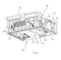
- Figure 1 shows a perspective bottom view of a laundry treating machine according to the invention with an upright side wall removed;
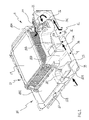
- Figure 2 shows a perspective sectional view of a basement of the laundry treating machine illustrated in Figure 1 .
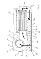
- Figure 3 shows a rear sectional view of air pumping means and condensing means arranged on the laundry treating machine basement illustrated in Figure 2 .
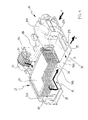
- Figure 4 shows a perspective sectional view of the laundry treating machine basement of Figure 2 from a reverse angle view.
- Figure 5 shows a perspective bottom view of the laundry treating machine basement of Figure 2 where a bottom wall portion has been removed;
- Figure 6 shows an exploded view of an attachment between an air flow conveyor and a bottom wall of the laundry treating machine basement illustrated in Figure 2 .
- Figure 7 shows a partially exploded view of the laundry treating machine basement illustrated in Figure 2 .
- a laundry treating machine comprises a casing 1 formed by two couples of upright side walls 2 arranged perpendicularly one another, respectively on the treating machine rear and front part, and on the lateral side thereof.
- a casing 1 formed by two couples of upright side walls 2 arranged perpendicularly one another, respectively on the treating machine rear and front part, and on the lateral side thereof.
- one of the lateral side walls has been removed for showing some of the laundry treating machine operational devices 5 accommodated within casing 1.
- An upper wall portion 3 and a bottom wall portion 4 close the ends of the box-like structure formed by the upright side walls 2 joined together.
- a laundry container 6 comprising a drum (not shown) rotatably mounted in a tub 7 is provided within the casing 1.
- An extractable moisture tank in the form of a drawer 9 is slidably arranged on the top of the casing 1, for being periodically emptied by a user in case the laundry treating machine cannot be connected to a waste water net through a pipe.
- a user control interface 10 is arranged on the top of the casing 1 near the drawer 9 for input of laundry treatment programs and displaying machine working conditions.
- air passage 11 On a bottom portion of the casing 1 and preferably in its front upright side wall 2 an air passage 11 is provided for draining air from/to the laundry treating machine.
- air passage 11 is divided into two portions 11A, 11B for allowing cooling air to enter and exit the casing 1, as indicated by arrows "I" and "O" in Figure 1 , in order to cool condensing means arranged in a drying air circuit passing through the laundry container 6 for removing moisture from said drying air.
- portions 11A and 11B of air passage 11 may be arranged on different upright side walls 2 other than the laundry treating machine front wall.
- an air passage 12 is formed as an opening 37 in the bottom wall portion 4.
- Such air passage 12 is always accessible to air because the bottom wall 4 extends in a position that is spaced apart and substantially parallel to a floor on which the laundry treating machine is placed.
- the distance between bottom wall 4 and a floor is determined in an adjustable manner through vertically adjustable supports 13 (only two of them are shown in Figure 1 ) placed under the casing 1.
- the bottom wall portion 4 comprises a sheet that is removably mounted onto a lower side 16 of (i.e. under) a basement 14 which is preferably made of polymeric material.
- the lower side 16 and the bottom wall portion 4 delimit a hollow space 38 adapted to convey air inside the machine and/or to discharge air outside the machine.
- bottom wall 4 rests on the same level of a lower edge 39 of basement 14 that surrounds a hollow space 38 upwardly limited by surfaces placed on a higher level relative to edge 39.
- seats 18A-18F are formed for receiving therein operational devices 5 of the laundry treating machine, like condensing means 19, air pumping means 20, motor means for powering air pumping means 20 and other functional devices for operating laundry treating machine to carry out a drying treatment on laundry as, for example, heat pump circuit components (not shown in Figure 1 ) like fluid compressing means, heat exchanging means, fluid condensing and/or evaporating means.
- basement 14 comprises a lower side 16 forming at least a portion of a first air path wherein the air is drawn in from outside the machine and/or the air is exhausted outside the machine and further comprises an upper side 17 forming at least a portion of a second air path that passes through one or more of said operational devices 5.
- FIG. 2 when the bottom wall portion 4 is associated under the basement 14 facing the lower side 16 of the latter, said bottom wall 4 substantially covers the hollow space 38 formed in the lower side 16 of basement 14 thereby forming an inlet conduit 15 for conveying air entering the laundry treating machine through air passages 11A, 12 as shown by arrows "I" and "II".
- Such conduit 15 has a lower surface 15A defined by the bottom wall 4 and upper surfaces 15B that are defined by the basement 14 itself through the surfaces upwardly limiting the hollow space 38 formed in the basement 14 lower side 16.
- air passage 12 in the bottom portion 14 may be the only aperture for allowing fluid communication between the environment where the laundry treating machine is installed and an air path circulating within said machine.
- air passage 12 may be in fluid communication with a laundry treatment air flow path, such as the drying air passing through the drum.
- Conduit 15 sucks air taken from outside by pumping means 20 for cooling condensing means 19 resting within seat 18A.
- Pumping means 20 are powered though an electric motor (not shown) housed in the seat 18B which is formed in the upper side 17 of basement 14. Said motor powers also further pumping means (not shown) that are arranged coaxially with pumping means 20 and received within seat 18D to circulate drying air through the laundry container 6. Motor means are interposed between pumping means 20 and those for circulating drying air. Rotational axis of the electric motor shaft extends parallel to the air flow path within conduit 15.
- Pumping means 20 that preferably comprises a centrifugal fan, are arranged on a level of the basement 14 that extends just over conduit 15 that rests on a lower level, therefore air path along conduit 15 is reversed and lead to said level by means of a conveyor 21 arranged between the air inlet port of pumping means 20 and conduit 15.
- Conveyor 21 is preferably made of felt and it is designed to reduce flow resistance when the air reverses its path of about 180 degrees increasing its height relative to the floor where the laundry treating machine rests. In this way performance of the laundry treating machine is not negatively affected, while an improved compactness in distributing operational devices on the basement 14 may be achieved.
- Conveyor 21 comprises an elongated cup-like body 22 having two opposite ends 23, 24 respectively adapted to be joined to a section of conduit 15 and to an air inlet port of pumping means 20. Said ends 23, 24 are linked each other by walls 25A, 25B, that cooperate with basement 14 to create a Venturi effect in the air flowing outside conduit 15 and entering pumping means 20 through conveyor 21.
- the inner transverse section surface area of said conveyor 21 gradually increases from the conveyor inlet port to be associated with conduit 15 to the conveyor outlet port to be associated with pumping means 20. Therefore while passing through conveyor 21, air increases its pressure and reduces its speed.
- a portion 26 (see Figures 1 and 3 ) of the basement 14 forms at least a part of a volute 31 and an air inlet port for pumping means 20 and it extends between ends 23, 24 thereby defining two separate ports for admitting and draining air from conveyor 21.
- volute 31 is formed by portion 26 of basement 14 and by a cover 32 which is removably attached to portion 26 through snap-fit fasteners 33 ( Figure 3 ) thereby closing seat 18C. Even though it is not shown in the Figures, a similar arrangement is also provided for pumping means received within seat 18D to circulate drying air through the laundry container 6.
- Conveyor 21 is arranged perpendicularly relative to bottom wall 4 and it is removably attached to said wall 4 by means of a spring clip 27 provided with protruding portions 27A, 27B that can be received within slots 28A, 28B formed onto the bottom wall 4 and within slots 29A formed onto a base member 30 in a position corresponding to that of slots 28A.
- spring clip 27 extends over the base member 30 with its protruding portions 27A and under the bottom wall 4 with its protruding portion 27B.
- Base member 30 lies over the bottom wall 4 on the lower surface 15A of conduit 15.
- a gasket may be over-injected on the edges of conveyor 21 that join conduit 15 and the edge of portion 26 defining the air inlet port of pumping means 20.
- condensing means 19 are in the form of an air-air cross-flow type heat exchanger When air passes through condensing means 19 its path lies on an upper level compared to the air flowing within conduit 15. Even the flow direction of air within conduit 15 is substantially perpendicular to that of air flowing through condensing means 19.
- Seat 18A, that houses condensing means 19, is shaped to diffuse air coming out from pumping means 20 to the whole surface of condensing means 19.
- FIG 3 it is shown from a rear sectional view of the basement 14 the air path flowing through condensing means 19 and then downwardly towards bottom wall 4.
- Air that exits condensing means 19 is guided from said upper side 17 to a lower side 16 of basement 14 by means of a conduit portion, or conveyor, 40 formed in the basement 14, for example by joining a cover to a upper side 17 of basement 14.
- Conveyor 40 may have the same features of conveyor 21, i.e. they may be substantially identical. Air conveyed by conduit portion 40 is also reversed in its flow direction of about 180 degrees and it is then received in an outlet conduit 34 which is formed in a manner similar to inlet conduit 15, i.e.
- FIG. 4 Another view of air path leaving condensing means 19 for entering outlet conduit 34 is shown in Figure 4 where outlet conduit 34 has been partly cut away and in Figure 5 where the bottom wall 4 has been removed.
- Outlet conduit 34 and inlet conduit 15 are separated and substantially tightly sealed by a partition 35 ( Figures 3 and 5 ) that extends downwardly (i.e. towards bottom wall 4) from joining region between upper surface 15B of inlet conduit 15 and upper surface 34B of outlet conduit 34.
- Upper surfaces 15B, 34B and partition 35 are made integrally, i.e. as a unitary body, such as a single-piece construction by molding.
- Outlet conduit 34 leads air from condensing means 19 to exit laundry treating machine through an outlet air passage 11B as indicated by arrow "O" in Figure 1 , 4 and 5 .
- Air coming out from air passage 11B hardly affects temperature of cooling air sucked into the laundry treating machine thanks to the provision of an air passage 12 in the bottom wall 4.
- provision of air passage 12 as the sole or auxiliary air inlet port ensures to provide the laundry treating machine with air in the conditions as it is in the environment where said machine is placed.
- Figure 7 further illustrates how the basement 14 can be assembled with conveyor 21 and further covers 32, 36 to house operational devices of laundry treating machine.
- Cover 36 in particular, is removably joined preferably by snap-fit means in the front upper part of the basement 14 to direct drying air flow from the condensing means 19 to the laundry container 6. Assembling operation of laundry treating machine, and, in general of its operational devices, may be greatly simplified and made more compact.
- the upper surfaces 15B, 34B of the basement 14 can comprise one or more opening so as to direct a part of the air flowing along the lower side 16 of the basement 14 into at least one of the seats 18A-18F for cooling purpose, for example to cool an electric motor or heat pump circuit components.
- a laundry treating machine according to the invention has an efficient arrangement for its basement portion which enhances layout of operational devices and air path formed thereon. Thanks to the basement arrangement according to the invention, noise produced by a laundry treating machine for moving air mass can be greatly lowered, thereby allowing the machine to be placed and operated both close to rooms where low noise or silent is required both during night hours.
- the present invention can be applied to any type of laundry treating machine, such as condenser-type laundry dryer and open-circuit laundry dryers, or to washing machines.
Landscapes
- Engineering & Computer Science (AREA)
- Mechanical Engineering (AREA)
- General Engineering & Computer Science (AREA)
- Textile Engineering (AREA)
- Detail Structures Of Washing Machines And Dryers (AREA)
- Accessory Of Washing/Drying Machine, Commercial Washing/Drying Machine, Other Washing/Drying Machine (AREA)
Abstract
Description
- Laundry treating machines capable of carrying out a drying process on laundry generally comprise a casing that houses a laundry container, like a rotating drum, where laundry to be treated is received, a basement portion having seats for receiving machine operational devices, and an air circuit for carrying out drying operation by circulating hot air through the laundry container. Air circulating means and heating means are provided in the air circuit for circulating and heating drying air, respectively. In condenser type dryers, condensing means are further provided in the air circuit for removing moisture from drying air passing through articles to be treated thereby allowing said air to be recirculated cyclically within the air circuit. Moisture removed from articles is either collected in a tank periodically emptied by a user or it is directly exhausted by a pipe connected to a waste water net.
- Washing-drying appliances, i.e. appliances provided for performing articles washing and drying operations in a single machine are also known and generally comprise a water circuit including pumping means for allowing washing water to be supplied to a laundry treating chamber and a drying arrangement as described before for drying laundry.
- In the following description the invention will be disclosed with particular reference to a machine suitable for carrying out a drying operation on laundry such as a laundry drying machine or a washing-drying machine. However, in general, principles of the invention may be applied to a laundry treating appliance, for example in cases when an air flow is needed to cool machine operating devices or part thereof.
- In a known condenser type laundry dryer, means for condensing moisture removed by articles are configured in many different ways. Typical examples comprise an air-air heat exchanger or an evaporator of a heat pump circuit incorporated within the dryer. Such condensing means or components thereof require to be cooled in order to constantly provide a cold surface where wet drying air can be condensed or to remove heat produced by said components, like a compressor in a heat pump circuit. Normally, air taken from dryer machine surroundings is used as cooling means of a condenser or components thereof. For this reason a plurality of conduits are provided on the lower portion of the laundry treating machine and, generally, a basement portion is appropriately designed to form at least a portion of cooling conduits.
- In prior art laundry drying machines such cooling conduits are generally formed on the upper side of machine basement, i.e. on the basement side facing the laundry container. However such construction is particularly disadvantageous because it complicates the arrangement of further machine operating devices like air pumping means, motor means and so on. A further drawback of such prior art laundry drying machines consists in that the position of air conduits on basement upper side causes the air ports on machine casing walls to be either placed at a high position relative to the machine resting surface or to be placed on lower region of casing lateral wall by complicatedly connecting them with air conduits. This arrangement definitely determines an efficiency reduction and therefore an increases in power losses.
- Another drawback of prior art laundry drying machines described above consists in high noise produced by cooling air circulating through conduits having complex and tortuous paths.
- The aim of the present invention is therefore to solve the noted drawbacks and thus providing a laundry treating machine having an improved basement arrangement.
- An object of the present invention is to provide a laundry treating machine with a basement having a more compact and rational design that improves arrangement of machine operational devices thereon.
- Another object of the present invention is to provide a laundry treating machine suitable for carrying out a drying process on laundry having an improved performance in cooling condensing means and/or components thereof, said laundry treating machine ensuring an efficient cooling air flow.
- A further object of the invention is to provide a laundry treating machine producing a low noise during working operation compared to laundry treating machine of known type.
- Another object of the invention is to provide a laundry treating machine which is easy to be assembled.
- Advantages, objects, and features of the invention will be set forth in part in the description and drawings which follow and in part will become apparent to those having ordinary skill in the art upon examination of the following or may be learned from practice of the invention.
- According to the present invention there is provided a laundry treating machine comprising a basement portion having an upper side with seats formed thereon for receiving machine operational devices, and a lower side, opposite to the upper side, characterized in that said lower side forms an air path for air to be admitted into or exhausted from said machine.
- Preferably, a bottom wall is associated to said lower side of basement such that at least one hollow space is formed therein to define said air path.
- Preferably, an air passage is formed on said bottom wall.
- Preferably, said at least one hollow space comprises a partition forming separated air conduits.
- Preferably, air flow direction along said separated air conduits is opposite.
- Preferably, said separated air conduits comprise, respectively, a fluid inlet opening and a fluid outlet opening.
- Preferably, a fluid inlet opening is provided on a front wall of a casing.
- Preferably, an outlet fluid opening is provided on the front wall of a casing.
- Preferably, said upper side of basement drives said air path towards the operational devices, said air path lying on different height levels of the basement.
- Preferably, a conveyor is provided for reversing said air path from one of said levels to the other.
- Preferably, said conveyor comprises an inner transverse section surface area which gradually increases from one of said layers to the other so as to create a Venturi effect.
- Preferably, said conveyor is arranged perpendicularly relative to the bottom wall and it is removably attached to said wall by means of a spring clip.
- Preferably, said air path comprises a cooling air open-circuit for cooling at least a part of said operational devices that comprise at least one of the following: motor means, fluid compressing means, heat exchanging means, fluid condensing and/or evaporating means, a portion of a heat pump circuit.
- Preferably, covers are provided for closing said seats.
- Preferably, said upper side of the basement forms a further air path for the air to pass through/over said operational device, said air path and said further air path extend at opposite side of the basement.
- Preferably, said laundry treating machine is a laundry dryer or a washing-drying appliance.
- The accompanying drawings, which are included to provide a further understanding of the invention and are incorporated in and constitute a part of this specification, illustrate a possible embodiment of the invention and together with the description serve to explain the principles of the invention. Like reference numbers represents like features throughout the accompanying drawings, wherein:
-
Figure 1 shows a perspective bottom view of a laundry treating machine according to the invention with an upright side wall removed; -
Figure 2 shows a perspective sectional view of a basement of the laundry treating machine illustrated inFigure 1 . -
Figure 3 shows a rear sectional view of air pumping means and condensing means arranged on the laundry treating machine basement illustrated inFigure 2 . -
Figure 4 shows a perspective sectional view of the laundry treating machine basement ofFigure 2 from a reverse angle view. -
Figure 5 shows a perspective bottom view of the laundry treating machine basement ofFigure 2 where a bottom wall portion has been removed; -
Figure 6 shows an exploded view of an attachment between an air flow conveyor and a bottom wall of the laundry treating machine basement illustrated inFigure 2 . -
Figure 7 shows a partially exploded view of the laundry treating machine basement illustrated inFigure 2 . - With reference to
Figure 1 , a laundry treating machine according to the invention comprises a casing 1 formed by two couples of upright side walls 2 arranged perpendicularly one another, respectively on the treating machine rear and front part, and on the lateral side thereof. InFigure 1 one of the lateral side walls has been removed for showing some of the laundry treating machine operational devices 5 accommodated within casing 1. An upper wall portion 3 and abottom wall portion 4 close the ends of the box-like structure formed by the upright side walls 2 joined together. - A
laundry container 6 comprising a drum (not shown) rotatably mounted in atub 7 is provided within the casing 1. Afront door 8, pivotally coupled to the front upright side wall 2, is provided for allowing access to the drum interior region to place laundry to be treated therein. An extractable moisture tank in the form of a drawer 9 is slidably arranged on the top of the casing 1, for being periodically emptied by a user in case the laundry treating machine cannot be connected to a waste water net through a pipe. A user control interface 10 is arranged on the top of the casing 1 near the drawer 9 for input of laundry treatment programs and displaying machine working conditions. - On a bottom portion of the casing 1 and preferably in its front upright side wall 2 an
air passage 11 is provided for draining air from/to the laundry treating machine. In the exemplary embodiment of the invention disclosed in the Figures,air passage 11 is divided into twoportions 11A, 11B for allowing cooling air to enter and exit the casing 1, as indicated by arrows "I" and "O" inFigure 1 , in order to cool condensing means arranged in a drying air circuit passing through thelaundry container 6 for removing moisture from said drying air. If desired,portions 11A and 11B ofair passage 11 may be arranged on different upright side walls 2 other than the laundry treating machine front wall. - According to the invention, an
air passage 12 is formed as an opening 37 in thebottom wall portion 4.Such air passage 12 is always accessible to air because thebottom wall 4 extends in a position that is spaced apart and substantially parallel to a floor on which the laundry treating machine is placed. The distance betweenbottom wall 4 and a floor is determined in an adjustable manner through vertically adjustable supports 13 (only two of them are shown inFigure 1 ) placed under the casing 1. Thebottom wall portion 4 comprises a sheet that is removably mounted onto alower side 16 of (i.e. under) abasement 14 which is preferably made of polymeric material. Thelower side 16 and thebottom wall portion 4 delimit ahollow space 38 adapted to convey air inside the machine and/or to discharge air outside the machine. - In particular,
bottom wall 4 rests on the same level of alower edge 39 ofbasement 14 that surrounds ahollow space 38 upwardly limited by surfaces placed on a higher level relative toedge 39. On anupper side 17 of thebasement 14,seats 18A-18F are formed for receiving therein operational devices 5 of the laundry treating machine, like condensing means 19, air pumping means 20, motor means for powering air pumping means 20 and other functional devices for operating laundry treating machine to carry out a drying treatment on laundry as, for example, heat pump circuit components (not shown inFigure 1 ) like fluid compressing means, heat exchanging means, fluid condensing and/or evaporating means. In practice,basement 14 comprises alower side 16 forming at least a portion of a first air path wherein the air is drawn in from outside the machine and/or the air is exhausted outside the machine and further comprises anupper side 17 forming at least a portion of a second air path that passes through one or more of said operational devices 5. - As shown in
Figure 2 , when thebottom wall portion 4 is associated under thebasement 14 facing thelower side 16 of the latter, saidbottom wall 4 substantially covers thehollow space 38 formed in thelower side 16 ofbasement 14 thereby forming aninlet conduit 15 for conveying air entering the laundry treating machine throughair passages 11A, 12 as shown by arrows "I" and "II".Such conduit 15 has alower surface 15A defined by thebottom wall 4 andupper surfaces 15B that are defined by thebasement 14 itself through the surfaces upwardly limiting thehollow space 38 formed in thebasement 14lower side 16. If desired,air passage 12 in thebottom portion 14 may be the only aperture for allowing fluid communication between the environment where the laundry treating machine is installed and an air path circulating within said machine. In particular,air passage 12 may be in fluid communication with a laundry treatment air flow path, such as the drying air passing through the drum. -
Conduit 15 sucks air taken from outside by pumpingmeans 20 for cooling condensing means 19 resting withinseat 18A. Pumping means 20 are powered though an electric motor (not shown) housed in theseat 18B which is formed in theupper side 17 ofbasement 14. Said motor powers also further pumping means (not shown) that are arranged coaxially with pumping means 20 and received withinseat 18D to circulate drying air through thelaundry container 6. Motor means are interposed between pumping means 20 and those for circulating drying air. Rotational axis of the electric motor shaft extends parallel to the air flow path withinconduit 15. - Pumping means 20, that preferably comprises a centrifugal fan, are arranged on a level of the
basement 14 that extends just overconduit 15 that rests on a lower level, therefore air path alongconduit 15 is reversed and lead to said level by means of aconveyor 21 arranged between the air inlet port of pumping means 20 andconduit 15.Conveyor 21 is preferably made of felt and it is designed to reduce flow resistance when the air reverses its path of about 180 degrees increasing its height relative to the floor where the laundry treating machine rests. In this way performance of the laundry treating machine is not negatively affected, while an improved compactness in distributing operational devices on thebasement 14 may be achieved. - In
Figure 6 it is shown in detail a configuration ofconveyor 21 and its attachment to thebottom wall 4.Conveyor 21 comprises an elongated cup-like body 22 having two opposite ends 23, 24 respectively adapted to be joined to a section ofconduit 15 and to an air inlet port of pumping means 20. Said ends 23, 24 are linked each other bywalls 25A, 25B, that cooperate withbasement 14 to create a Venturi effect in the air flowing outsideconduit 15 and entering pumping means 20 throughconveyor 21. For this aim, the inner transverse section surface area of saidconveyor 21 gradually increases from the conveyor inlet port to be associated withconduit 15 to the conveyor outlet port to be associated with pumping means 20. Therefore while passing throughconveyor 21, air increases its pressure and reduces its speed. A portion 26 (seeFigures 1 and3 ) of thebasement 14 forms at least a part of avolute 31 and an air inlet port for pumping means 20 and it extends between ends 23, 24 thereby defining two separate ports for admitting and draining air fromconveyor 21. As can be seen inFigure 7 ,volute 31 is formed byportion 26 ofbasement 14 and by acover 32 which is removably attached toportion 26 through snap-fit fasteners 33 (Figure 3 ) thereby closingseat 18C. Even though it is not shown in the Figures, a similar arrangement is also provided for pumping means received withinseat 18D to circulate drying air through thelaundry container 6. -
Conveyor 21 is arranged perpendicularly relative tobottom wall 4 and it is removably attached to saidwall 4 by means of aspring clip 27 provided with protrudingportions slots bottom wall 4 and withinslots 29A formed onto abase member 30 in a position corresponding to that ofslots 28A. When in locking condition,spring clip 27 extends over thebase member 30 with its protrudingportions 27A and under thebottom wall 4 with its protrudingportion 27B.Base member 30 lies over thebottom wall 4 on thelower surface 15A ofconduit 15. In order to tightly sealconveyor 21 onto theconduit 15 outlet section and the air inlet port of pumping means 20, a gasket may be over-injected on the edges ofconveyor 21 that joinconduit 15 and the edge ofportion 26 defining the air inlet port of pumping means 20. - Air sucked by pumping
means 20 is output centrifugally from the latter and directed towards condensing means 19 as shown by arrows inFigure 2 . Preferably, condensing means 19 are in the form of an air-air cross-flow type heat exchanger When air passes through condensing means 19 its path lies on an upper level compared to the air flowing withinconduit 15. Even the flow direction of air withinconduit 15 is substantially perpendicular to that of air flowing through condensing means 19.Seat 18A, that houses condensing means 19, is shaped to diffuse air coming out from pumping means 20 to the whole surface of condensing means 19. - In
Figure 3 it is shown from a rear sectional view of thebasement 14 the air path flowing through condensing means 19 and then downwardly towardsbottom wall 4. Air that exits condensing means 19 is guided from saidupper side 17 to alower side 16 ofbasement 14 by means of a conduit portion, or conveyor, 40 formed in thebasement 14, for example by joining a cover to aupper side 17 ofbasement 14.Conveyor 40 may have the same features ofconveyor 21, i.e. they may be substantially identical. Air conveyed byconduit portion 40 is also reversed in its flow direction of about 180 degrees and it is then received in anoutlet conduit 34 which is formed in a manner similar toinlet conduit 15, i.e. by alower surface 34A defined by thebottom wall 4 and anupper surface 34B that is defined by thebasement 14 itself through the surface upwardly limiting a furtherhollow space 38 formed in thebasement 14lower side 16. Another view of air path leaving condensing means 19 for enteringoutlet conduit 34 is shown inFigure 4 whereoutlet conduit 34 has been partly cut away and inFigure 5 where thebottom wall 4 has been removed.Outlet conduit 34 andinlet conduit 15 are separated and substantially tightly sealed by a partition 35 (Figures 3 and5 ) that extends downwardly (i.e. towards bottom wall 4) from joining region betweenupper surface 15B ofinlet conduit 15 andupper surface 34B ofoutlet conduit 34.Upper surfaces partition 35 are made integrally, i.e. as a unitary body, such as a single-piece construction by molding. -
Outlet conduit 34 leads air from condensing means 19 to exit laundry treating machine through anoutlet air passage 11B as indicated by arrow "O" inFigure 1 ,4 and5 . Air coming out fromair passage 11B hardly affects temperature of cooling air sucked into the laundry treating machine thanks to the provision of anair passage 12 in thebottom wall 4. In fact, provision ofair passage 12 as the sole or auxiliary air inlet port ensures to provide the laundry treating machine with air in the conditions as it is in the environment where said machine is placed. -
Figure 7 further illustrates how thebasement 14 can be assembled withconveyor 21 and further covers 32, 36 to house operational devices of laundry treating machine.Cover 36, in particular, is removably joined preferably by snap-fit means in the front upper part of thebasement 14 to direct drying air flow from the condensing means 19 to thelaundry container 6. Assembling operation of laundry treating machine, and, in general of its operational devices, may be greatly simplified and made more compact. - Preferably, the
upper surfaces basement 14 can comprise one or more opening so as to direct a part of the air flowing along thelower side 16 of thebasement 14 into at least one of theseats 18A-18F for cooling purpose, for example to cool an electric motor or heat pump circuit components. - Conclusively it can be stated that a laundry treating machine according to the invention has an efficient arrangement for its basement portion which enhances layout of operational devices and air path formed thereon. Thanks to the basement arrangement according to the invention, noise produced by a laundry treating machine for moving air mass can be greatly lowered, thereby allowing the machine to be placed and operated both close to rooms where low noise or silent is required both during night hours.
- The present invention can be applied to any type of laundry treating machine, such as condenser-type laundry dryer and open-circuit laundry dryers, or to washing machines.
Claims (15)
- A laundry treating machine comprising a basement portion (14) having an upper side (17) with seats (18A-18F) formed thereon for receiving machine operational devices (5), and a lower side (16), opposite to the upper side (17), characterized in that said lower side (16) forms an air path for air to be admitted into or exhausted from said machine.
- A laundry treating machine according to claim 1, wherein a bottom wall (4) is associated to said lower side (16) of basement (14) such that at least one hollow space (38) is formed therein to define said air path.
- A laundry treating machine according to claim 2, wherein an air passage (12) is formed on said bottom wall (4).
- A laundry treating machine according to claim 2 wherein said at least one hollow space (38) comprises a partition (35) forming separated air conduits (15,34).
- A laundry treating machine according to claim 4 wherein air flow direction along said separated air conduits (15, 34) is opposite.
- A laundry treating machine according to claim 4 or 5 wherein said separated air conduits (15, 34) comprise, respectively, a fluid inlet opening (11A, 37) and a fluid outlet opening (11B).
- A laundry treating machine according to any preceding claim wherein a fluid inlet opening (11A) is provided on a front wall (2) of a casing (1).
- A laundry treating machine according to any preceding claim wherein an outlet fluid opening (11B) is provided on the front wall (2) of a casing (1).
- A laundry treating machine according to any preceding claim wherein said upper side (17) of basement (14) drives said air path towards the operational devices (5), said air path lying on different height levels of the basement (14).
- A laundry treating machine according to claim 9 wherein a conveyor (21, 40) is provided for reversing said air path from one of said levels to the other.
- A laundry treating machine according to claim 10 wherein said conveyor (21, 40) comprises an inner transverse section surface area which gradually increases from one of said layers to the other so as to create a Venturi effect.
- A laundry treating machine according to claim 10 or 11 wherein said conveyor (21, 40) is arranged perpendicularly relative to the bottom wall (4) and it is removably attached to said wall (4) by means of a spring clip (27).
- A laundry treating machine according to any preceding claim wherein said air path comprises a cooling air open-circuit for cooling at least a part of said operational devices (5) that comprise at least one of the following: motor means, fluid compressing means, heat exchanging means, fluid condensing and/or evaporating means, a portion of a heat pump circuit.
- A laundry treating machine according to any preceding claim wherein covers (32, 36) are provided for closing said seats (18A-18F).
- A laundry treating machine according to any preceding claim wherein said machine is a laundry dryer or a washing-drying appliance.
Priority Applications (6)
| Application Number | Priority Date | Filing Date | Title |
|---|---|---|---|
| EP10173931A EP2423371A1 (en) | 2010-08-25 | 2010-08-25 | Laundry treating machine |
| US13/211,566 US8844163B2 (en) | 2010-08-25 | 2011-08-17 | Laundry treating machine with basement portion providing airflow paths |
| CN201110243211.4A CN102383294B (en) | 2010-08-25 | 2011-08-24 | Laundry Treating Machine |
| RU2011135416/12A RU2011135416A (en) | 2010-08-25 | 2011-08-24 | UNDERWATER MACHINE |
| BRPI1104222A BRPI1104222A2 (en) | 2010-08-25 | 2011-08-25 | washer and dryer |
| US14/487,700 US9534843B2 (en) | 2010-08-25 | 2014-09-16 | Laundry treating machine with basement portion providing airflow paths |
Applications Claiming Priority (1)
| Application Number | Priority Date | Filing Date | Title |
|---|---|---|---|
| EP10173931A EP2423371A1 (en) | 2010-08-25 | 2010-08-25 | Laundry treating machine |
Publications (1)
| Publication Number | Publication Date |
|---|---|
| EP2423371A1 true EP2423371A1 (en) | 2012-02-29 |
Family
ID=43608744
Family Applications (1)
| Application Number | Title | Priority Date | Filing Date |
|---|---|---|---|
| EP10173931A Withdrawn EP2423371A1 (en) | 2010-08-25 | 2010-08-25 | Laundry treating machine |
Country Status (5)
| Country | Link |
|---|---|
| US (2) | US8844163B2 (en) |
| EP (1) | EP2423371A1 (en) |
| CN (1) | CN102383294B (en) |
| BR (1) | BRPI1104222A2 (en) |
| RU (1) | RU2011135416A (en) |
Families Citing this family (16)
| Publication number | Priority date | Publication date | Assignee | Title |
|---|---|---|---|---|
| EP2423371A1 (en) * | 2010-08-25 | 2012-02-29 | Electrolux Home Products Corporation N.V. | Laundry treating machine |
| EP2458072A1 (en) * | 2010-11-29 | 2012-05-30 | Electrolux Home Products Corporation N.V. | Laundry dryer |
| EP2487290B1 (en) * | 2011-02-10 | 2014-05-07 | Electrolux Home Products Corporation N.V. | Home laundry drier |
| WO2015154081A2 (en) * | 2014-04-05 | 2015-10-08 | Brown Michael E | Apparatus and method for drying articles of clothing |
| DE102014216485A1 (en) * | 2014-08-20 | 2016-02-25 | BSH Hausgeräte GmbH | Floor module for a household appliance |
| CN106521908A (en) * | 2015-09-09 | 2017-03-22 | 无锡小天鹅股份有限公司 | A clothes dryer |
| EP3252220A1 (en) * | 2016-05-31 | 2017-12-06 | Wuxi Little Swan Co., Ltd. | Heat pump module for laundry treatment device and laundry treatment device |
| US9863086B2 (en) * | 2016-05-31 | 2018-01-09 | Wuxi Little Swan Co., Ltd. | Heat pump mounting box and heat pump drier or heat pump washer-drier |
| CN106012455A (en) * | 2016-06-30 | 2016-10-12 | 无锡小天鹅股份有限公司 | Clothes dryer and base assembly thereof |
| CN106592176B (en) * | 2016-11-30 | 2019-05-21 | 无锡小天鹅股份有限公司 | Straight-line dryer and condensing unit for straight-line dryer |
| US10443178B2 (en) | 2017-09-01 | 2019-10-15 | Whirlpool Corporation | Rear panel and basement damping treatments for a laundry appliance |
| US11008696B2 (en) | 2018-12-28 | 2021-05-18 | Whirlpool Corporation | Supplemental condensate delivery system having a snap-in drain member |
| CN111394970B (en) * | 2019-01-03 | 2024-12-20 | 无锡小天鹅电器有限公司 | Reinforcement plate, clothes drying module and clothes treating device |
| CN111394952B (en) * | 2019-01-03 | 2025-04-18 | 无锡小天鹅电器有限公司 | Clothes treatment device |
| KR102336988B1 (en) * | 2020-01-16 | 2021-12-08 | 엘지전자 주식회사 | A laundry treating apparatus |
| US11891749B2 (en) | 2020-11-23 | 2024-02-06 | Whirlpool Corporation | Under-cabinet seal to prevent exhaust recirculation for a condensing appliance |
Citations (10)
| Publication number | Priority date | Publication date | Assignee | Title |
|---|---|---|---|---|
| US2742708A (en) * | 1952-07-12 | 1956-04-24 | Gen Motors Corp | Domestic appliance |
| GB2145206A (en) * | 1983-08-16 | 1985-03-20 | Ti Domestic Appliances Ltd | Laundry drying equipment |
| JPH01242098A (en) * | 1988-03-24 | 1989-09-27 | Matsushita Electric Ind Co Ltd | clothes dryer |
| EP0481187A1 (en) * | 1990-10-17 | 1992-04-22 | Zanker GmbH | Laundry drier |
| EP1518957A1 (en) * | 2003-09-24 | 2005-03-30 | Lg Electronics Inc. | Condensing-type dryer |
| WO2006104327A1 (en) * | 2005-03-31 | 2006-10-05 | Lg Electronics, Inc. | Laundry dryer |
| EP1865102A1 (en) * | 2005-03-23 | 2007-12-12 | Ibai, S. Coop | Clothes-smoothing and drying wardrobe |
| EP1925712A1 (en) * | 2006-11-24 | 2008-05-28 | CANDY S.p.A. | Laundry drier with circuit to limit internal condensation |
| WO2008127027A2 (en) * | 2007-04-13 | 2008-10-23 | Lg Electronics Inc. | Auxiliary laundry treating machine and multiple treating system including the same |
| EP2113595A1 (en) * | 2008-04-30 | 2009-11-04 | Lg Electronics Inc. | Laundry machine |
Family Cites Families (37)
| Publication number | Priority date | Publication date | Assignee | Title |
|---|---|---|---|---|
| US2503329A (en) | 1946-03-08 | 1950-04-11 | Nineteen Hundred Corp | Clothes drier |
| US2694867A (en) | 1952-02-06 | 1954-11-23 | Lovell Mfg Co | Drier |
| US2830384A (en) | 1956-10-24 | 1958-04-15 | Westinghouse Electric Corp | Dryer for fabrics or the like |
| IT1217752B (en) | 1988-06-01 | 1990-03-30 | Merloni A Spa | PET LINEN DRYING MACHINE |
| US5066050A (en) * | 1989-05-22 | 1991-11-19 | Whirlpool Corporation | Dryer transition duct |
| US5369892A (en) | 1993-06-04 | 1994-12-06 | Dhaemers; Gregory L. | Armoire |
| US6088932A (en) | 1997-12-30 | 2000-07-18 | Amana Company, L.P. | Efficiency clothes dryer |
| JP2001070697A (en) | 1999-09-06 | 2001-03-21 | Sanyo Electric Co Ltd | Clothing dryer |
| IT1311719B1 (en) | 1999-11-29 | 2002-03-19 | Electrolux Zanussi Elettrodome | ROTATING BASKET METHOD AND APPARATUS OF THE CONDENSING TYPE FOR DRYING LINEN |
| US20030126691A1 (en) | 2001-12-20 | 2003-07-10 | Gerlach Christian Gerhard Friedrich | Fabric article treating method and apparatus |
| KR100487759B1 (en) | 2003-08-13 | 2005-05-06 | 엘지전자 주식회사 | Induction structure of cool air for clothing dryer |
| RU2006114770A (en) | 2003-09-29 | 2007-11-10 | Селф Пропеллед Рисерч энд Дивелопмент Спешелистс,эЛэЛСи (US) | DRYING DEVICE (OPTIONS), WASHING DEVICE AND DRYING CHAMBER (OPTIONS) |
| JP3739377B2 (en) | 2003-12-10 | 2006-01-25 | シャープ株式会社 | Washing and drying machine |
| US7036243B2 (en) | 2003-12-22 | 2006-05-02 | Lg Electronics Inc. | Laundry dryer and condenser assembly thereof |
| KR101021778B1 (en) | 2003-12-26 | 2011-03-15 | 엘지전자 주식회사 | Drainage passage structure of the condenser lower part of the dryer |
| US6877248B1 (en) | 2004-03-05 | 2005-04-12 | Gregory N. Cross | Clothes dryer with ultraviolet light |
| CN1973077B (en) | 2004-12-06 | 2011-08-03 | Lg电子株式会社 | clothes dryer |
| DE102005013051A1 (en) | 2005-03-18 | 2006-09-21 | BSH Bosch und Siemens Hausgeräte GmbH | Condensation Dryer |
| KR100638904B1 (en) * | 2005-03-31 | 2006-10-25 | 엘지전자 주식회사 | Clothes dryer |
| DE102005013053A1 (en) | 2005-05-23 | 2006-11-30 | BSH Bosch und Siemens Hausgeräte GmbH | Condensation Dryer |
| KR101180532B1 (en) | 2005-05-23 | 2012-09-06 | 엘지전자 주식회사 | Laundry dryer having apparatus for storing condensed water |
| US7188435B2 (en) | 2005-07-20 | 2007-03-13 | Woolston Bonnie E | Knock-down type dryer assembly for prosthesis liners |
| KR100664282B1 (en) | 2005-12-21 | 2007-01-04 | 엘지전자 주식회사 | Heat pump system modular housing of clothes dryer and clothes dryer comprising the same |
| US7913419B2 (en) | 2005-12-30 | 2011-03-29 | Whirlpool Corporation | Non-tumble clothes dryer |
| DE102006005809B4 (en) | 2006-02-08 | 2012-05-24 | BSH Bosch und Siemens Hausgeräte GmbH | Condenser dryer comprising a capacitor housing with at least one thin wall |
| US20080141555A1 (en) | 2006-12-15 | 2008-06-19 | Electrolux Home Products, Inc. | Dryer housing and venting arrangement facilitating venting options |
| US20090064530A1 (en) | 2007-08-03 | 2009-03-12 | Lg Electronics Inc. | Clothes treatment apparatus |
| DE102007052839A1 (en) | 2007-11-06 | 2009-05-07 | BSH Bosch und Siemens Hausgeräte GmbH | Dryer with heat pump circuit |
| DE102008010519A1 (en) | 2008-02-22 | 2009-09-03 | BSH Bosch und Siemens Hausgeräte GmbH | Dryer with cooled engine |
| DE102008033388B4 (en) | 2008-07-16 | 2020-07-16 | BSH Hausgeräte GmbH | Dryer with heat pump circuit |
| KR101485850B1 (en) | 2008-09-10 | 2015-01-26 | 삼성전자 주식회사 | Clothes dryer |
| KR20100034077A (en) | 2008-09-23 | 2010-04-01 | 삼성전자주식회사 | Clothing dryer |
| DE102008044277A1 (en) | 2008-12-02 | 2010-06-10 | BSH Bosch und Siemens Hausgeräte GmbH | Dryer with a heat pump and an electric heater and method of operation |
| KR101030171B1 (en) * | 2008-12-17 | 2011-04-18 | 엘지전자 주식회사 | dryer |
| US8490438B2 (en) | 2009-02-05 | 2013-07-23 | Lg Electronics Inc. | Laundry treatment device |
| EP2423371A1 (en) * | 2010-08-25 | 2012-02-29 | Electrolux Home Products Corporation N.V. | Laundry treating machine |
| EP2423378B1 (en) | 2010-08-25 | 2013-04-17 | Electrolux Home Products Corporation N.V. | Laundry treating machine |
-
2010
- 2010-08-25 EP EP10173931A patent/EP2423371A1/en not_active Withdrawn
-
2011
- 2011-08-17 US US13/211,566 patent/US8844163B2/en active Active
- 2011-08-24 CN CN201110243211.4A patent/CN102383294B/en not_active Expired - Fee Related
- 2011-08-24 RU RU2011135416/12A patent/RU2011135416A/en not_active Application Discontinuation
- 2011-08-25 BR BRPI1104222A patent/BRPI1104222A2/en not_active Application Discontinuation
-
2014
- 2014-09-16 US US14/487,700 patent/US9534843B2/en not_active Expired - Fee Related
Patent Citations (10)
| Publication number | Priority date | Publication date | Assignee | Title |
|---|---|---|---|---|
| US2742708A (en) * | 1952-07-12 | 1956-04-24 | Gen Motors Corp | Domestic appliance |
| GB2145206A (en) * | 1983-08-16 | 1985-03-20 | Ti Domestic Appliances Ltd | Laundry drying equipment |
| JPH01242098A (en) * | 1988-03-24 | 1989-09-27 | Matsushita Electric Ind Co Ltd | clothes dryer |
| EP0481187A1 (en) * | 1990-10-17 | 1992-04-22 | Zanker GmbH | Laundry drier |
| EP1518957A1 (en) * | 2003-09-24 | 2005-03-30 | Lg Electronics Inc. | Condensing-type dryer |
| EP1865102A1 (en) * | 2005-03-23 | 2007-12-12 | Ibai, S. Coop | Clothes-smoothing and drying wardrobe |
| WO2006104327A1 (en) * | 2005-03-31 | 2006-10-05 | Lg Electronics, Inc. | Laundry dryer |
| EP1925712A1 (en) * | 2006-11-24 | 2008-05-28 | CANDY S.p.A. | Laundry drier with circuit to limit internal condensation |
| WO2008127027A2 (en) * | 2007-04-13 | 2008-10-23 | Lg Electronics Inc. | Auxiliary laundry treating machine and multiple treating system including the same |
| EP2113595A1 (en) * | 2008-04-30 | 2009-11-04 | Lg Electronics Inc. | Laundry machine |
Also Published As
| Publication number | Publication date |
|---|---|
| US8844163B2 (en) | 2014-09-30 |
| US20120049704A1 (en) | 2012-03-01 |
| US20150000153A1 (en) | 2015-01-01 |
| RU2011135416A (en) | 2013-03-10 |
| BRPI1104222A2 (en) | 2016-01-19 |
| CN102383294B (en) | 2015-07-15 |
| US9534843B2 (en) | 2017-01-03 |
| CN102383294A (en) | 2012-03-21 |
Similar Documents
| Publication | Publication Date | Title |
|---|---|---|
| US9534843B2 (en) | Laundry treating machine with basement portion providing airflow paths | |
| EP2423378B1 (en) | Laundry treating machine | |
| EP2423376A1 (en) | Laundry treating machine | |
| EP1961361B1 (en) | Drying system for a dishwasher | |
| US7866061B2 (en) | Clothes dryer | |
| CN103748279B (en) | Clothes treatment device | |
| US10214842B2 (en) | Washing machine | |
| CN113355841A (en) | Stacked clothes treating device | |
| KR20100034077A (en) | Clothing dryer | |
| CN106661815B (en) | Heat Pump Clothes Dryer | |
| JP3920299B2 (en) | Clothes dryer | |
| WO2006054431A1 (en) | Drum-type washer-dryer | |
| EP2594689A1 (en) | Laundry drying machine | |
| CN115404633A (en) | Clothes treatment device | |
| EP4219822B1 (en) | Dryer with high air tigthness of a process air circuit and process for operating the dryer | |
| CN220572167U (en) | Water-steam separation device, dish washer inner bag and dish washer | |
| EP2669424B1 (en) | Laundry treating machine | |
| JP2012210513A (en) | Drying unit and drying device | |
| EP0699795B1 (en) | An improved washing/drying machine for laundry | |
| JP2010279786A (en) | Drying unit and drying device | |
| KR20160015575A (en) | Washing machine | |
| KR20160015576A (en) | Washing machine | |
| KR20160015577A (en) | Washing machine |
Legal Events
| Date | Code | Title | Description |
|---|---|---|---|
| AK | Designated contracting states |
Kind code of ref document: A1 Designated state(s): AL AT BE BG CH CY CZ DE DK EE ES FI FR GB GR HR HU IE IS IT LI LT LU LV MC MK MT NL NO PL PT RO SE SI SK SM TR |
|
| AX | Request for extension of the european patent |
Extension state: BA ME RS |
|
| PUAI | Public reference made under article 153(3) epc to a published international application that has entered the european phase |
Free format text: ORIGINAL CODE: 0009012 |
|
| RIN1 | Information on inventor provided before grant (corrected) |
Inventor name: PASUT, FABIO Inventor name: PALAZZIN, DEBORAH Inventor name: VIAN, ALESSANDRO |
|
| 17P | Request for examination filed |
Effective date: 20120829 |
|
| 17Q | First examination report despatched |
Effective date: 20161006 |
|
| STAA | Information on the status of an ep patent application or granted ep patent |
Free format text: STATUS: THE APPLICATION IS DEEMED TO BE WITHDRAWN |
|
| 18D | Application deemed to be withdrawn |
Effective date: 20181003 |