EP2423346A1 - Minimizing Blockage of Holes in Turbine Engine Components - Google Patents
Minimizing Blockage of Holes in Turbine Engine Components Download PDFInfo
- Publication number
- EP2423346A1 EP2423346A1 EP11179392A EP11179392A EP2423346A1 EP 2423346 A1 EP2423346 A1 EP 2423346A1 EP 11179392 A EP11179392 A EP 11179392A EP 11179392 A EP11179392 A EP 11179392A EP 2423346 A1 EP2423346 A1 EP 2423346A1
- Authority
- EP
- European Patent Office
- Prior art keywords
- plug
- airfoil
- ceramic
- coating
- hole
- Prior art date
- Legal status (The legal status is an assumption and is not a legal conclusion. Google has not performed a legal analysis and makes no representation as to the accuracy of the status listed.)
- Granted
Links
Images


Classifications
-
- C—CHEMISTRY; METALLURGY
- C23—COATING METALLIC MATERIAL; COATING MATERIAL WITH METALLIC MATERIAL; CHEMICAL SURFACE TREATMENT; DIFFUSION TREATMENT OF METALLIC MATERIAL; COATING BY VACUUM EVAPORATION, BY SPUTTERING, BY ION IMPLANTATION OR BY CHEMICAL VAPOUR DEPOSITION, IN GENERAL; INHIBITING CORROSION OF METALLIC MATERIAL OR INCRUSTATION IN GENERAL
- C23C—COATING METALLIC MATERIAL; COATING MATERIAL WITH METALLIC MATERIAL; SURFACE TREATMENT OF METALLIC MATERIAL BY DIFFUSION INTO THE SURFACE, BY CHEMICAL CONVERSION OR SUBSTITUTION; COATING BY VACUUM EVAPORATION, BY SPUTTERING, BY ION IMPLANTATION OR BY CHEMICAL VAPOUR DEPOSITION, IN GENERAL
- C23C4/00—Coating by spraying the coating material in the molten state, e.g. by flame, plasma or electric discharge
- C23C4/12—Coating by spraying the coating material in the molten state, e.g. by flame, plasma or electric discharge characterised by the method of spraying
-
- C—CHEMISTRY; METALLURGY
- C23—COATING METALLIC MATERIAL; COATING MATERIAL WITH METALLIC MATERIAL; CHEMICAL SURFACE TREATMENT; DIFFUSION TREATMENT OF METALLIC MATERIAL; COATING BY VACUUM EVAPORATION, BY SPUTTERING, BY ION IMPLANTATION OR BY CHEMICAL VAPOUR DEPOSITION, IN GENERAL; INHIBITING CORROSION OF METALLIC MATERIAL OR INCRUSTATION IN GENERAL
- C23C—COATING METALLIC MATERIAL; COATING MATERIAL WITH METALLIC MATERIAL; SURFACE TREATMENT OF METALLIC MATERIAL BY DIFFUSION INTO THE SURFACE, BY CHEMICAL CONVERSION OR SUBSTITUTION; COATING BY VACUUM EVAPORATION, BY SPUTTERING, BY ION IMPLANTATION OR BY CHEMICAL VAPOUR DEPOSITION, IN GENERAL
- C23C14/00—Coating by vacuum evaporation, by sputtering or by ion implantation of the coating forming material
- C23C14/04—Coating on selected surface areas, e.g. using masks
- C23C14/042—Coating on selected surface areas, e.g. using masks using masks
-
- C—CHEMISTRY; METALLURGY
- C23—COATING METALLIC MATERIAL; COATING MATERIAL WITH METALLIC MATERIAL; CHEMICAL SURFACE TREATMENT; DIFFUSION TREATMENT OF METALLIC MATERIAL; COATING BY VACUUM EVAPORATION, BY SPUTTERING, BY ION IMPLANTATION OR BY CHEMICAL VAPOUR DEPOSITION, IN GENERAL; INHIBITING CORROSION OF METALLIC MATERIAL OR INCRUSTATION IN GENERAL
- C23C—COATING METALLIC MATERIAL; COATING MATERIAL WITH METALLIC MATERIAL; SURFACE TREATMENT OF METALLIC MATERIAL BY DIFFUSION INTO THE SURFACE, BY CHEMICAL CONVERSION OR SUBSTITUTION; COATING BY VACUUM EVAPORATION, BY SPUTTERING, BY ION IMPLANTATION OR BY CHEMICAL VAPOUR DEPOSITION, IN GENERAL
- C23C4/00—Coating by spraying the coating material in the molten state, e.g. by flame, plasma or electric discharge
- C23C4/01—Selective coating, e.g. pattern coating, without pre-treatment of the material to be coated
-
- C—CHEMISTRY; METALLURGY
- C23—COATING METALLIC MATERIAL; COATING MATERIAL WITH METALLIC MATERIAL; CHEMICAL SURFACE TREATMENT; DIFFUSION TREATMENT OF METALLIC MATERIAL; COATING BY VACUUM EVAPORATION, BY SPUTTERING, BY ION IMPLANTATION OR BY CHEMICAL VAPOUR DEPOSITION, IN GENERAL; INHIBITING CORROSION OF METALLIC MATERIAL OR INCRUSTATION IN GENERAL
- C23C—COATING METALLIC MATERIAL; COATING MATERIAL WITH METALLIC MATERIAL; SURFACE TREATMENT OF METALLIC MATERIAL BY DIFFUSION INTO THE SURFACE, BY CHEMICAL CONVERSION OR SUBSTITUTION; COATING BY VACUUM EVAPORATION, BY SPUTTERING, BY ION IMPLANTATION OR BY CHEMICAL VAPOUR DEPOSITION, IN GENERAL
- C23C4/00—Coating by spraying the coating material in the molten state, e.g. by flame, plasma or electric discharge
- C23C4/02—Pretreatment of the material to be coated, e.g. for coating on selected surface areas
-
- C—CHEMISTRY; METALLURGY
- C23—COATING METALLIC MATERIAL; COATING MATERIAL WITH METALLIC MATERIAL; CHEMICAL SURFACE TREATMENT; DIFFUSION TREATMENT OF METALLIC MATERIAL; COATING BY VACUUM EVAPORATION, BY SPUTTERING, BY ION IMPLANTATION OR BY CHEMICAL VAPOUR DEPOSITION, IN GENERAL; INHIBITING CORROSION OF METALLIC MATERIAL OR INCRUSTATION IN GENERAL
- C23C—COATING METALLIC MATERIAL; COATING MATERIAL WITH METALLIC MATERIAL; SURFACE TREATMENT OF METALLIC MATERIAL BY DIFFUSION INTO THE SURFACE, BY CHEMICAL CONVERSION OR SUBSTITUTION; COATING BY VACUUM EVAPORATION, BY SPUTTERING, BY ION IMPLANTATION OR BY CHEMICAL VAPOUR DEPOSITION, IN GENERAL
- C23C4/00—Coating by spraying the coating material in the molten state, e.g. by flame, plasma or electric discharge
- C23C4/12—Coating by spraying the coating material in the molten state, e.g. by flame, plasma or electric discharge characterised by the method of spraying
- C23C4/137—Spraying in vacuum or in an inert atmosphere
-
- F—MECHANICAL ENGINEERING; LIGHTING; HEATING; WEAPONS; BLASTING
- F01—MACHINES OR ENGINES IN GENERAL; ENGINE PLANTS IN GENERAL; STEAM ENGINES
- F01D—NON-POSITIVE DISPLACEMENT MACHINES OR ENGINES, e.g. STEAM TURBINES
- F01D5/00—Blades; Blade-carrying members; Heating, heat-insulating, cooling or antivibration means on the blades or the members
- F01D5/12—Blades
- F01D5/14—Form or construction
- F01D5/18—Hollow blades, i.e. blades with cooling or heating channels or cavities; Heating, heat-insulating or cooling means on blades
- F01D5/186—Film cooling
-
- F—MECHANICAL ENGINEERING; LIGHTING; HEATING; WEAPONS; BLASTING
- F01—MACHINES OR ENGINES IN GENERAL; ENGINE PLANTS IN GENERAL; STEAM ENGINES
- F01D—NON-POSITIVE DISPLACEMENT MACHINES OR ENGINES, e.g. STEAM TURBINES
- F01D5/00—Blades; Blade-carrying members; Heating, heat-insulating, cooling or antivibration means on the blades or the members
- F01D5/12—Blades
- F01D5/28—Selecting particular materials; Particular measures relating thereto; Measures against erosion or corrosion
- F01D5/288—Protective coatings for blades
-
- F—MECHANICAL ENGINEERING; LIGHTING; HEATING; WEAPONS; BLASTING
- F05—INDEXING SCHEMES RELATING TO ENGINES OR PUMPS IN VARIOUS SUBCLASSES OF CLASSES F01-F04
- F05D—INDEXING SCHEME FOR ASPECTS RELATING TO NON-POSITIVE-DISPLACEMENT MACHINES OR ENGINES, GAS-TURBINES OR JET-PROPULSION PLANTS
- F05D2230/00—Manufacture
- F05D2230/30—Manufacture with deposition of material
- F05D2230/31—Layer deposition
- F05D2230/312—Layer deposition by plasma spraying
-
- F—MECHANICAL ENGINEERING; LIGHTING; HEATING; WEAPONS; BLASTING
- F05—INDEXING SCHEMES RELATING TO ENGINES OR PUMPS IN VARIOUS SUBCLASSES OF CLASSES F01-F04
- F05D—INDEXING SCHEME FOR ASPECTS RELATING TO NON-POSITIVE-DISPLACEMENT MACHINES OR ENGINES, GAS-TURBINES OR JET-PROPULSION PLANTS
- F05D2250/00—Geometry
- F05D2250/70—Shape
-
- F—MECHANICAL ENGINEERING; LIGHTING; HEATING; WEAPONS; BLASTING
- F05—INDEXING SCHEMES RELATING TO ENGINES OR PUMPS IN VARIOUS SUBCLASSES OF CLASSES F01-F04
- F05D—INDEXING SCHEME FOR ASPECTS RELATING TO NON-POSITIVE-DISPLACEMENT MACHINES OR ENGINES, GAS-TURBINES OR JET-PROPULSION PLANTS
- F05D2300/00—Materials; Properties thereof
- F05D2300/10—Metals, alloys or intermetallic compounds
- F05D2300/13—Refractory metals, i.e. Ti, V, Cr, Zr, Nb, Mo, Hf, Ta, W
-
- F—MECHANICAL ENGINEERING; LIGHTING; HEATING; WEAPONS; BLASTING
- F05—INDEXING SCHEMES RELATING TO ENGINES OR PUMPS IN VARIOUS SUBCLASSES OF CLASSES F01-F04
- F05D—INDEXING SCHEME FOR ASPECTS RELATING TO NON-POSITIVE-DISPLACEMENT MACHINES OR ENGINES, GAS-TURBINES OR JET-PROPULSION PLANTS
- F05D2300/00—Materials; Properties thereof
- F05D2300/20—Oxide or non-oxide ceramics
- F05D2300/21—Oxide ceramics
Definitions
- the present invention relates to a method for minimizing blockage of holes in turbine engine components such as blades or vanes during the application of plasma spray coatings.
- airfoils hollow, air-cooled blades and vanes
- airfoils air-cooled blades and vanes
- air is flowed into an internal cavity of the airfoils and is discharged through cooling holes present in a section of the airfoil, its platform and/or tip thereof.
- the passage of air through the airfoil extracts heat from the airfoil surface allowing use of the airfoil even if gas stream temperatures exceed the melting temperature of the alloy from which the airfoil is made.
- Obstruction of the cooling holes can result in hot spots on the airfoil that may cause cracking or localized melting of the airfoil, and/or degradation of a protective coating that may be present on the airfoil surface.
- powders may be injected into a high temperature high velocity stream of ionized gases. At the point where the powders are injected into the gas stream, the temperatures can be very high. As a result, the powders are typically molten when they strike the substrate surface.
- cooling holes can become filled with coating material, requiring a subsequent machine operation to open the holes. This is not only time consuming and therefore expensive, but locating the exact position of each hole is difficult.
- One known method uses a high pressure stream of gas that is flowed into the internal cavity of the airfoil during the coating operation. The gas is discharged through the cooling holes to deflect the incoming coating particles away from the holes, thereby keeping the holes open. Unless gas is discharged evenly through each of the holes, some holes are still likely to become plugged. A common practice is to drill the holes after coating is applied.
- plugs are inserted into the cooling holes of hollow, air cooled airfoils prior to the plasma spray coating operation.
- the plugs are ablative and the plasma spray stream causes a portion of the head of each plug to volatilize during the spray operation.
- the plugs are sized to provide a sufficient amount of material that can be sacrificed during the spray operation so that at the end of the operation, the plug heads continue to protrude above the surface of the coating.
- the plugs are removed from the coated component by heating the component at elevated temperatures for a time sufficient to cause complete volatilization to open up the holes.
- an airfoil having a hole therein.
- a ceramic plug is inserted in the hole so that the plug extends above a depth of a thermal barrier coating, such as a ceramic, to be placed on the airfoil.
- the airfoil is then coated by a substantially non-line of sight vapor deposition and the plugs are then removed.
- an airfoil has a hole therein.
- a plug is manipulated to fit within the hole, wherein the plug extends above a depth of a ceramic coating to be placed on the airfoil.
- the airfoil is coated by non-line of sight vapor deposition, and then the plug is removed by manipulating the plug.
- an airfoil has a hole therein.
- a refractory metal plug is inserted in the hole, wherein the plug extends above a depth of a ceramic coating to be placed on the airfoil.
- the airfoil is coated by non-line of sight vapor deposition, and then the plug is removed.
- an airfoil has a hole therein.
- a plug constructed of a material having a greater coefficient of thermal expansion than the nickel blade in the hole is inserted in the hole, wherein the plug extends above a depth of a ceramic coating to be placed on the airfoil.
- the airfoil is coated by non-line of sight vapor deposition, and then the plug is removed.
- FIG 1 is a view of an airfoil 10 having an airfoil section 12, a tip section 14, a platform section 16 and a root section 18. Because a turbine engine vane (not shown) has a similar airfoil section 12, the term “airfoil” is meant to mean blade as well as a vane or other surface that is be air cooled. Airfoil 10 has cooling holes 20 that are dictated by the particular operating characteristics and cooling requirements of the airfoil 10 and engine (not shown). The number, size and location of the holes 20 shown in Figure 1 is meant to be illustrative of the use of the invention is not intended as limiting the scope of the invention.
- a coating 25 (see Figure 2 ), such as a ceramic (as will be discussed more in depth hereinbelow), that is applied to the airfoil 10 can affect the condition of the cooling holes.
- the airfoil section 12 is shown schematically in figure 1 as being disposed within a physical vapor deposition chamber (“PVD") 35.
- PVD physical vapor deposition chamber
- the airfoil shown herein is a constructed of a nickel-based material and is placed in the PVD chamber for the deposition of a ceramic coating of material to protect the airfoil from the rigors of heat encountered in the combustion section of a gas turbine engine (not shown).
- the coating 25 may minimize the effects of higher temperatures the nickel airfoil 10 encounters within the gas turbine engine.
- the coating 25 may also be known as a thermal barrier coating ("TBC").
- TBC thermal barrier coating
- Other airfoil materials that are coated are contemplated herein.
- NLOS non-line of sight technologies
- a transonic gas jet 40 directs and transports a thermally evaporated vapor cloud 45 into and around an airfoil 10 to reach deeply concave or other hidden or complex surfaces of the airfoil uniformly. Collisions between the vapor atoms and gas jet create a mechanism for controlling vapor transport. The probability of clogging of holes 20 is much higher in such a system.
- plugs 30 are inserted into holes 20, stick in place therein, survive the higher temperature PVD chamber 35 environment and are relatively easy to get out.
- the plug 30 could be any ceramic such as a 7% yttria stabilized zirconia or a gadolinia zirconia or any other appropriate combination of zirconia with a rare earth oxide such as dysprosia.
- the plugs 30 can also be a zirconia based ceramic powder mixed with binder, such as a polymer, a wax, or the like etc.
- the plugs may also be any high temperature metal that is coated with a lamina, which may be ceramic slurry.
- the plug 30 may also be made of a material, such as cobalt based alloys or austenitic stainless steel, having a higher coefficient of thermal expansion than the airfoil section 12 so that heating of the airfoil section 12 causes the plug 30 to tightly fit within the hole 20 during processing and cooling makes the plugs 30 easy to remove.
- the plugs may also be formed of ceramic slurry.
- the plugs may be coated with a ceramic powder.
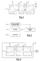
- a method of processing a airfoil 10 is described as follows: plugs 30 are inserted in the holes 20 such that they extend beyond a coating depth D (step 50) (see Fig.2 ), the airfoil 10 is processed in the PVD chamber 35, and the plugs 30 are removed by vibrating the airfoil by a vibrator (shown schematically 85) which minimizes or destroys the integrity of the plugs causing them to fall away, by placing them in an oven and burning the plugs 30 away, or by removing them physically.
- a vibrator shown schematically 85
- the plugs may be burned away if they are made of a refractory material, such as zirconium, titanium, molybdenum, hafnium, tantalum or tungsten, or the like, that would react with oxygen when heated in air. Zirconium would be a good choice because the PVD chamber 35 would not be contaminated if the plug fell out during processing of the airfoil section 12.
- a plug 30 has a squeezable shape 90, like an omega though other shapes may be used herein, with a bulbous top 95, a narrow body 100 and splayed legs 105 from the narrow body 100. If the bulbous top 95 is squeezed or manipulated, the legs 105 move toward each other allowing them room to fit within the holes 20. If the bulbous top is released from squeezing, the legs 105 move outwardly trapping the narrow body 100 in the hole between the bulbous top 95 and the legs. After coating the process is reversed, the bulbous top 95 is squeezed causing the legs 105 to move toward each other allowing them room to be removed from the holes 20.
Landscapes
- Chemical & Material Sciences (AREA)
- Engineering & Computer Science (AREA)
- Mechanical Engineering (AREA)
- Materials Engineering (AREA)
- Chemical Kinetics & Catalysis (AREA)
- Metallurgy (AREA)
- Organic Chemistry (AREA)
- Physics & Mathematics (AREA)
- Plasma & Fusion (AREA)
- General Engineering & Computer Science (AREA)
- Turbine Rotor Nozzle Sealing (AREA)
Abstract
Description
- The present invention relates to a method for minimizing blockage of holes in turbine engine components such as blades or vanes during the application of plasma spray coatings.
- The use of hollow, air-cooled blades and vanes (hereinafter referred to collectively as "airfoils") is common in modem gas turbine engines. During engine operation, air is flowed into an internal cavity of the airfoils and is discharged through cooling holes present in a section of the airfoil, its platform and/or tip thereof. The passage of air through the airfoil extracts heat from the airfoil surface allowing use of the airfoil even if gas stream temperatures exceed the melting temperature of the alloy from which the airfoil is made. Obstruction of the cooling holes can result in hot spots on the airfoil that may cause cracking or localized melting of the airfoil, and/or degradation of a protective coating that may be present on the airfoil surface.
- In the plasma spray coating process, powders may be injected into a high temperature high velocity stream of ionized gases. At the point where the powders are injected into the gas stream, the temperatures can be very high. As a result, the powders are typically molten when they strike the substrate surface.
- If coatings are sprayed onto air cooled airfoils, cooling holes can become filled with coating material, requiring a subsequent machine operation to open the holes. This is not only time consuming and therefore expensive, but locating the exact position of each hole is difficult. One known method uses a high pressure stream of gas that is flowed into the internal cavity of the airfoil during the coating operation. The gas is discharged through the cooling holes to deflect the incoming coating particles away from the holes, thereby keeping the holes open. Unless gas is discharged evenly through each of the holes, some holes are still likely to become plugged. A common practice is to drill the holes after coating is applied.
- According to a further methodology, plugs are inserted into the cooling holes of hollow, air cooled airfoils prior to the plasma spray coating operation. The plugs are ablative and the plasma spray stream causes a portion of the head of each plug to volatilize during the spray operation. The plugs are sized to provide a sufficient amount of material that can be sacrificed during the spray operation so that at the end of the operation, the plug heads continue to protrude above the surface of the coating. The plugs are removed from the coated component by heating the component at elevated temperatures for a time sufficient to cause complete volatilization to open up the holes.
- Sometimes the holes are welded shut before coating is applied, and then are drilled out after the coating process. All such techniques are expensive and time consuming; therefore, improved techniques are desired.
- According to an exemplar method for coating an airfoil disclosed herein, an airfoil, the airfoil having a hole therein. A ceramic plug is inserted in the hole so that the plug extends above a depth of a thermal barrier coating, such as a ceramic, to be placed on the airfoil. The airfoil is then coated by a substantially non-line of sight vapor deposition and the plugs are then removed.
- According to another exemplar method for coating an airfoil disclosed herein, an airfoil has a hole therein. A plug is manipulated to fit within the hole, wherein the plug extends above a depth of a ceramic coating to be placed on the airfoil. The airfoil is coated by non-line of sight vapor deposition, and then the plug is removed by manipulating the plug.
- According to a further exemplar method for coating an airfoil disclosed herein, an airfoil has a hole therein. A refractory metal plug is inserted in the hole, wherein the plug extends above a depth of a ceramic coating to be placed on the airfoil. The airfoil is coated by non-line of sight vapor deposition, and then the plug is removed.
- According to a still further exemplar method for coating an airfoil disclosed herein, an airfoil has a hole therein. A plug constructed of a material having a greater coefficient of thermal expansion than the nickel blade in the hole is inserted in the hole, wherein the plug extends above a depth of a ceramic coating to be placed on the airfoil. The airfoil is coated by non-line of sight vapor deposition, and then the plug is removed.
- These and other features of the disclosed examples can be best understood from the following specification and drawings, the following of which is a brief description.
-
-
Figure 1 is a perspective view of an airfoil used in a modem gas turbine engine. -
Figure 2 shows a portion of the surface of the airfoil ofFigure 1 taken along the line 2-2. -
Figure 3 shows a method of protecting holes in the airfoil ofFigure 1 . -
Figure 4 shows a removal of the plugs ofFigure 2 . -
Figure 5 is a cross-sectional view of a further embodiment of a plug. -
Figure 1 is a view of anairfoil 10 having anairfoil section 12, atip section 14, aplatform section 16 and aroot section 18. Because a turbine engine vane (not shown) has asimilar airfoil section 12, the term "airfoil" is meant to mean blade as well as a vane or other surface that is be air cooled. Airfoil 10 hascooling holes 20 that are dictated by the particular operating characteristics and cooling requirements of theairfoil 10 and engine (not shown). The number, size and location of theholes 20 shown inFigure 1 is meant to be illustrative of the use of the invention is not intended as limiting the scope of the invention. - Maintaining
cooling holes 20 in an unobstructed condition as well as keeping the size and shape of theholes 20 within design limits is essential to achieve desired performance of theairfoil 10 during engine operation. A coating 25 (seeFigure 2 ), such as a ceramic (as will be discussed more in depth hereinbelow), that is applied to theairfoil 10 can affect the condition of the cooling holes. - The
airfoil section 12 is shown schematically infigure 1 as being disposed within a physical vapor deposition chamber ("PVD") 35. The airfoil shown herein is a constructed of a nickel-based material and is placed in the PVD chamber for the deposition of a ceramic coating of material to protect the airfoil from the rigors of heat encountered in the combustion section of a gas turbine engine (not shown). Thecoating 25 may minimize the effects of higher temperatures thenickel airfoil 10 encounters within the gas turbine engine. Thecoating 25 may also be known as a thermal barrier coating ("TBC"). Other airfoil materials that are coated are contemplated herein. - Current techniques, including conventional Electron Beam PVD techniques, used to coat
turbine airfoils 12 with thermal barrier coatings are typically line-of-sight. These coating techniques offer limited capability to go in deeply concave or other hidden or complex surfaces. As a result, the achievable coating thickness is limited and coating distribution is inconsistent on complexly-shaped parts. Moreover, more conventional line-of-sight PVD techniques are infrequently focused long enough on aparticular hole 20 to cause significant clogging with coating 25. - However, non-line of sight technologies ("NLOS") are being developed that allow for coating on complex shaped parts such as
airfoil 10. For instance, atransonic gas jet 40 directs and transports a thermally evaporatedvapor cloud 45 into and around anairfoil 10 to reach deeply concave or other hidden or complex surfaces of the airfoil uniformly. Collisions between the vapor atoms and gas jet create a mechanism for controlling vapor transport. The probability of clogging ofholes 20 is much higher in such a system. - According to an example herein,
plugs 30 are inserted intoholes 20, stick in place therein, survive the highertemperature PVD chamber 35 environment and are relatively easy to get out. Theplug 30 could be any ceramic such as a 7% yttria stabilized zirconia or a gadolinia zirconia or any other appropriate combination of zirconia with a rare earth oxide such as dysprosia. Theplugs 30 can also be a zirconia based ceramic powder mixed with binder, such as a polymer, a wax, or the like etc. The plugs may also be any high temperature metal that is coated with a lamina, which may be ceramic slurry. Theplug 30 may also be made of a material, such as cobalt based alloys or austenitic stainless steel, having a higher coefficient of thermal expansion than theairfoil section 12 so that heating of theairfoil section 12 causes theplug 30 to tightly fit within thehole 20 during processing and cooling makes theplugs 30 easy to remove. The plugs may also be formed of ceramic slurry. The plugs may be coated with a ceramic powder. - Referring now to
Figures 3 and 4 , a method of processing aairfoil 10 is described as follows: plugs 30 are inserted in theholes 20 such that they extend beyond a coating depth D (step 50) (seeFig.2 ), theairfoil 10 is processed in thePVD chamber 35, and theplugs 30 are removed by vibrating the airfoil by a vibrator (shown schematically 85) which minimizes or destroys the integrity of the plugs causing them to fall away, by placing them in an oven and burning theplugs 30 away, or by removing them physically. The plugs may be burned away if they are made of a refractory material, such as zirconium, titanium, molybdenum, hafnium, tantalum or tungsten, or the like, that would react with oxygen when heated in air. Zirconium would be a good choice because thePVD chamber 35 would not be contaminated if the plug fell out during processing of theairfoil section 12. - Referring to
Figure 5 , aplug 30 has asqueezable shape 90, like an omega though other shapes may be used herein, with a bulbous top 95, anarrow body 100 and splayedlegs 105 from thenarrow body 100. If the bulbous top 95 is squeezed or manipulated, thelegs 105 move toward each other allowing them room to fit within theholes 20. If the bulbous top is released from squeezing, thelegs 105 move outwardly trapping thenarrow body 100 in the hole between the bulbous top 95 and the legs. After coating the process is reversed, the bulbous top 95 is squeezed causing thelegs 105 to move toward each other allowing them room to be removed from theholes 20. - Although a combination of features is shown in the illustrated examples, not all of them need to be combined to realize the benefits of various embodiments of this disclosure. In other words, a system designed according to an embodiment of this disclosure will not necessarily include all of the features shown in any one of the Figures or all of the portions schematically shown in the Figures. Moreover, selected features of one example embodiment may be combined with selected features of other example embodiments.
- The preceding description is exemplary rather than limiting in nature. Variations and modifications to the disclosed examples may become apparent to those skilled in the art that do not necessarily depart from the essence of this disclosure. Thus, the scope of legal protection given to this disclosure can only be determined by studying the following claims.
Claims (15)
- A method for coating an airfoil (10), said method comprising;
providing an airfoil (10), said airfoil (10) having a hole (20) therein, inserting a plug (30) into said hole (20), wherein said plug (30) extends above a depth (D) of a ceramic coating (25) to be placed on said airfoil (10),
coating said airfoil (10) by a non-line of sight vapor deposition, and removing said plug (30). - The method of claim 1 wherein said plug (30) is ceramic.
- The method of claim 2 wherein said plug (30) comprises a ceramic powder mixed with a binder.
- The method of claim 3 wherein said binder is wax.
- The method of claim 2 wherein said ceramic plug (30) is a slurry.
- The method of any of claims 2 to 5 wherein said ceramic plug (30) has a metallic core.
- The method of any of claims 2 to 6 wherein said ceramic plug (30) is coated with a ceramic powder.
- The method of claim 1 wherein said plug is a refractory metal plug, for example any of zirconium, titanium, molybdenum, hafnium, tantalum or tungsten.
- The method of any preceding claim wherein said plug (30) is constructed of a material having a greater coefficient of thermal expansion than said airfoil material, for example any of a cobalt-based alloy or austenitic stainless steel.
- The method of any preceding claim wherein said removing said plug (30) comprises the step of vibrating said plug (30).
- The method of any of claims 1 to 9 wherein said removing said plug (30) comprises the step of burning said plug (30) out of said hole (20).
- The method of any preceding claim wherein said plug (30) is manipulated to fit within said hole (20).
- The method of claim 10 wherein said manipulating requires said plug (30) to be squeezed.
- The method of claim 11 wherein said plug (30) has an omega shape (90).
- The method of any preceding claim wherein said airfoil is nickel-based.
Applications Claiming Priority (1)
| Application Number | Priority Date | Filing Date | Title |
|---|---|---|---|
| US12/871,028 US9206499B2 (en) | 2010-08-30 | 2010-08-30 | Minimizing blockage of holes in turbine engine components |
Publications (2)
| Publication Number | Publication Date |
|---|---|
| EP2423346A1 true EP2423346A1 (en) | 2012-02-29 |
| EP2423346B1 EP2423346B1 (en) | 2013-05-29 |
Family
ID=44582492
Family Applications (1)
| Application Number | Title | Priority Date | Filing Date |
|---|---|---|---|
| EP11179392.3A Active EP2423346B1 (en) | 2010-08-30 | 2011-08-30 | Minimizing blockage of holes in turbine engine components |
Country Status (2)
| Country | Link |
|---|---|
| US (1) | US9206499B2 (en) |
| EP (1) | EP2423346B1 (en) |
Cited By (7)
| Publication number | Priority date | Publication date | Assignee | Title |
|---|---|---|---|---|
| EP2674510A1 (en) * | 2012-06-15 | 2013-12-18 | General Electric Company | Channel marker and related methods |
| WO2015031034A3 (en) * | 2013-08-29 | 2015-04-23 | General Electric Company | Thermal spray coating method and thermal spray coated article |
| WO2015047507A3 (en) * | 2013-07-26 | 2015-05-21 | Siemens Energy, Inc. | Trailing edge cooling arrangement for an airfoil of a gas turbine engine |
| EP2913420A3 (en) * | 2013-12-06 | 2015-11-04 | General Electric Company | Coating methods and a coated substrate |
| EP3000973A1 (en) * | 2014-09-24 | 2016-03-30 | United Technologies Corporation | Self-modulated cooling on turbine components |
| CN106715747A (en) * | 2014-12-03 | 2017-05-24 | 三菱日立电力系统株式会社 | Sprayed-coating formation method, high-temperature component for turbine, turbine, and masking member and masking pin for sprayed-coating formation |
| KR20190026524A (en) * | 2017-09-05 | 2019-03-13 | 한화에어로스페이스 주식회사 | Hole processing method of component |
Families Citing this family (11)
| Publication number | Priority date | Publication date | Assignee | Title |
|---|---|---|---|---|
| US9518317B2 (en) * | 2012-05-11 | 2016-12-13 | General Electric Company | Method of coating a component, method of forming cooling holes and a water soluble aperture plug |
| US9884343B2 (en) * | 2012-12-20 | 2018-02-06 | United Technologies Corporation | Closure of cooling holes with a filling agent |
| US9765623B2 (en) | 2013-07-23 | 2017-09-19 | General Electric Company | Methods for modifying cooling holes with recess-shaped modifications |
| US9416667B2 (en) | 2013-11-22 | 2016-08-16 | General Electric Company | Modified turbine components with internally cooled supplemental elements and methods for making the same |
| EP2883977A1 (en) | 2013-12-11 | 2015-06-17 | Siemens Aktiengesellschaft | Method for coating a component with holes |
| US11203693B2 (en) | 2016-09-23 | 2021-12-21 | General Electric Company | Method of coating an article, paste and plug for preventing hole blockage during coating |
| US10717101B2 (en) * | 2018-02-16 | 2020-07-21 | General Electric Company | Method for making cooling assembly for a turbomachine part |
| US10888892B2 (en) * | 2018-08-23 | 2021-01-12 | General Electric Company | Protecting hole in component during coating process using plug with water soluble layer |
| US11225707B2 (en) * | 2019-08-13 | 2022-01-18 | General Electric Company | Protective shields for improved coating of turbine component cooling features |
| US11174738B1 (en) * | 2020-05-06 | 2021-11-16 | General Electric Company | Sacrificial plug system |
| CN114990468A (en) * | 2022-06-08 | 2022-09-02 | 哈尔滨汽轮机厂有限责任公司 | Preparation method of gas turbine combustor transition section thermal barrier coating for protecting gas film divergence hole |
Citations (4)
| Publication number | Priority date | Publication date | Assignee | Title |
|---|---|---|---|---|
| EP0253754A1 (en) * | 1986-07-14 | 1988-01-20 | United Technologies Corporation | Method for preventing closure of cooling holes in hollow air cooled turbine engine components during application of a plasma spray coating |
| WO1999023274A1 (en) * | 1997-11-03 | 1999-05-14 | Siemens Aktiengesellschaft | GAZ JET PVD METHOD FOR PRODUCING A LAYER WITH MoSi¿2? |
| EP1835045A1 (en) * | 2006-03-15 | 2007-09-19 | Siemens Aktiengesellschaft | Process for obtaining a coated part |
| DE102006029071B3 (en) * | 2006-06-16 | 2007-10-04 | Siemens Ag | Method for coating a component with a surface having holes (13) not to be coated comprises filling the holes with a mask material before coating the surface |
Family Cites Families (42)
| Publication number | Priority date | Publication date | Assignee | Title |
|---|---|---|---|---|
| US1647090A (en) | 1925-12-26 | 1927-10-25 | Globus Henry | Perforated illuminated sign and its manufacture |
| US2324568A (en) | 1942-04-08 | 1943-07-20 | Duggan James Edward | Paint mask structure |
| US2363660A (en) | 1942-04-08 | 1944-11-28 | Duggan James Edward | Bearing mask structure |
| BE475874A (en) | 1945-04-17 | |||
| US3196043A (en) | 1961-05-17 | 1965-07-20 | Gen Electric | Method for making an electrode structure |
| US3380863A (en) | 1966-03-31 | 1968-04-30 | Purex Corp Ltd | Method of etching with a strippable maskant |
| US3565664A (en) | 1968-01-24 | 1971-02-23 | Schlumberger Technology Corp | Methods for masking selected portions of articles to be coated |
| US3667988A (en) | 1969-07-09 | 1972-06-06 | Nagoya Yukagaku Kogyo Kk | Masking in surface treatment of articles |
| US3695340A (en) | 1970-05-04 | 1972-10-03 | Parsons John T | Multi-part combustible casting pattern having bend-resistant glue-less joints |
| US3972974A (en) | 1970-09-04 | 1976-08-03 | Pico Francisco A | Manufacture of abrasion-resistant screening apparatus |
| US4128522A (en) | 1976-07-30 | 1978-12-05 | Gulf & Western Industries, Inc. | Method and maskant composition for preventing the deposition of a coating on a substrate |
| US4170513A (en) * | 1978-06-06 | 1979-10-09 | Fernand Piche Enterprises Limited | Recovery of tungsten carbide from scrap mining bits |
| US4264647A (en) | 1979-04-17 | 1981-04-28 | General Motors Corporation | Reference electrode printing process and mask for exhaust gas oxygen sensor |
| US4396503A (en) | 1981-08-10 | 1983-08-02 | Hein Lehmann Ag | Method and device for coating elements and screen elements made thereby |
| US4402992A (en) | 1981-12-07 | 1983-09-06 | The United States Of America As Represented By The Administrator Of The National Aeronautics And Space Administration | Covering solid, film cooled surfaces with a duplex thermal barrier coating |
| FR2529315A1 (en) | 1982-06-25 | 1983-12-30 | Commissariat Energie Atomique | METHOD FOR SELECTIVELY SEPARATING THE END OF A MODULE AND A MODULE OBTAINED THEREBY |
| US4479890A (en) | 1982-10-05 | 1984-10-30 | Rca Corporation | Thick film resistor inks |
| US4530861A (en) | 1983-12-19 | 1985-07-23 | General Electric Company | Method and apparatus for masking a surface of a blade member |
| GB8611448D0 (en) * | 1986-05-10 | 1986-06-18 | Nl Petroleum Prod | Rotary drill bits |
| JPS63250488A (en) * | 1987-04-06 | 1988-10-18 | Murata Mfg Co Ltd | Plating method |
| US5468681A (en) | 1989-08-28 | 1995-11-21 | Lsi Logic Corporation | Process for interconnecting conductive substrates using an interposer having conductive plastic filled vias |
| JPH0414784A (en) | 1990-05-08 | 1992-01-20 | Masao Iwanaga | Electro-discharge element, manufacture and applied device thereof |
| US5130163A (en) | 1991-04-26 | 1992-07-14 | General Motors Corporation | Porous laminate surface coating method |
| US5304331A (en) | 1992-07-23 | 1994-04-19 | Minnesota Mining And Manufacturing Company | Method and apparatus for extruding bingham plastic-type materials |
| US5441767A (en) | 1994-01-26 | 1995-08-15 | United Technologies Corporation | Pack coating process for articles containing small passageways |
| US5726348A (en) | 1996-06-25 | 1998-03-10 | United Technologies Corporation | Process for precisely closing off cooling holes of an airfoil |
| US5800695A (en) | 1996-10-16 | 1998-09-01 | Chromalloy Gas Turbine Corporation | Plating turbine engine components |
| US5902647A (en) | 1996-12-03 | 1999-05-11 | General Electric Company | Method for protecting passage holes in a metal-based substrate from becoming obstructed, and related compositions |
| US5985122A (en) | 1997-09-26 | 1999-11-16 | General Electric Company | Method for preventing plating of material in surface openings of turbine airfoils |
| EP1029103B1 (en) | 1997-11-03 | 2001-09-19 | Siemens Aktiengesellschaft | Coating method and device |
| GB9723762D0 (en) | 1997-11-12 | 1998-01-07 | Rolls Royce Plc | A method of coating a component |
| US6018856A (en) * | 1998-05-26 | 2000-02-01 | Ehrhart; Gary | Device for removing and inserting the retaining clip of a coal mining drill bit |
| US6161804A (en) * | 1999-01-12 | 2000-12-19 | Andrew Corporation | Transmission line hanger |
| DE69911948T2 (en) * | 1999-08-09 | 2004-11-04 | Alstom Technology Ltd | Method for closing cooling openings of a gas turbine component |
| US6238743B1 (en) * | 2000-01-20 | 2001-05-29 | General Electric Company | Method of removing a thermal barrier coating |
| JP2002241176A (en) * | 2001-02-13 | 2002-08-28 | Minebea Co Ltd | Ceramic material, producing method therefor and molding thereof |
| EP1327483A1 (en) | 2002-01-15 | 2003-07-16 | Siemens Aktiengesellschaft | Process for coating a substrate comprising holes |
| EP1365039A1 (en) | 2002-05-24 | 2003-11-26 | ALSTOM (Switzerland) Ltd | Process of masking colling holes of a gas turbine component |
| DE60310168T2 (en) | 2002-08-02 | 2007-09-13 | Alstom Technology Ltd. | Method for protecting partial surfaces of a workpiece |
| US6863930B2 (en) * | 2002-09-06 | 2005-03-08 | Delphi Technologies, Inc. | Refractory metal mask and methods for coating an article and forming a sensor |
| JP4260450B2 (en) * | 2002-09-20 | 2009-04-30 | 東京エレクトロン株式会社 | Manufacturing method of electrostatic chuck in vacuum processing apparatus |
| US7658590B1 (en) | 2005-09-30 | 2010-02-09 | Florida Turbine Technologies, Inc. | Turbine airfoil with micro-tubes embedded with a TBC |
-
2010
- 2010-08-30 US US12/871,028 patent/US9206499B2/en active Active
-
2011
- 2011-08-30 EP EP11179392.3A patent/EP2423346B1/en active Active
Patent Citations (4)
| Publication number | Priority date | Publication date | Assignee | Title |
|---|---|---|---|---|
| EP0253754A1 (en) * | 1986-07-14 | 1988-01-20 | United Technologies Corporation | Method for preventing closure of cooling holes in hollow air cooled turbine engine components during application of a plasma spray coating |
| WO1999023274A1 (en) * | 1997-11-03 | 1999-05-14 | Siemens Aktiengesellschaft | GAZ JET PVD METHOD FOR PRODUCING A LAYER WITH MoSi¿2? |
| EP1835045A1 (en) * | 2006-03-15 | 2007-09-19 | Siemens Aktiengesellschaft | Process for obtaining a coated part |
| DE102006029071B3 (en) * | 2006-06-16 | 2007-10-04 | Siemens Ag | Method for coating a component with a surface having holes (13) not to be coated comprises filling the holes with a mask material before coating the surface |
Cited By (18)
| Publication number | Priority date | Publication date | Assignee | Title |
|---|---|---|---|---|
| CN103511058A (en) * | 2012-06-15 | 2014-01-15 | 通用电气公司 | Channel marker and related methods |
| CN103511058B (en) * | 2012-06-15 | 2019-07-09 | 通用电气公司 | Path marking and associated method |
| US9303517B2 (en) | 2012-06-15 | 2016-04-05 | General Electric Company | Channel marker and related methods |
| EP2674510A1 (en) * | 2012-06-15 | 2013-12-18 | General Electric Company | Channel marker and related methods |
| US10150187B2 (en) | 2013-07-26 | 2018-12-11 | Siemens Energy, Inc. | Trailing edge cooling arrangement for an airfoil of a gas turbine engine |
| WO2015047507A3 (en) * | 2013-07-26 | 2015-05-21 | Siemens Energy, Inc. | Trailing edge cooling arrangement for an airfoil of a gas turbine engine |
| WO2015031034A3 (en) * | 2013-08-29 | 2015-04-23 | General Electric Company | Thermal spray coating method and thermal spray coated article |
| US10775115B2 (en) | 2013-08-29 | 2020-09-15 | General Electric Company | Thermal spray coating method and thermal spray coated article |
| JP2016531205A (en) * | 2013-08-29 | 2016-10-06 | ゼネラル・エレクトリック・カンパニイ | Thermal spray coating method and thermal spray coated article |
| US9551058B2 (en) | 2013-12-06 | 2017-01-24 | General Electric Company | Coating methods and a coated substrate |
| EP2913420A3 (en) * | 2013-12-06 | 2015-11-04 | General Electric Company | Coating methods and a coated substrate |
| US9845731B2 (en) | 2014-09-24 | 2017-12-19 | United Technologies Corporation | Self-modulated cooling on turbine components |
| EP3000973A1 (en) * | 2014-09-24 | 2016-03-30 | United Technologies Corporation | Self-modulated cooling on turbine components |
| EP3608507A1 (en) * | 2014-09-24 | 2020-02-12 | United Technologies Corporation | Self-modulated cooling on turbine components |
| CN106715747A (en) * | 2014-12-03 | 2017-05-24 | 三菱日立电力系统株式会社 | Sprayed-coating formation method, high-temperature component for turbine, turbine, and masking member and masking pin for sprayed-coating formation |
| CN106715747B (en) * | 2014-12-03 | 2019-07-26 | 三菱日立电力系统株式会社 | Spraying plating epithelium forming method |
| US11148169B2 (en) | 2014-12-03 | 2021-10-19 | Mitsubishi Power, Ltd. | Method of forming sprayed coating, high-temperature component for turbine, turbine, masking pin for forming sprayed coating, and masking member |
| KR20190026524A (en) * | 2017-09-05 | 2019-03-13 | 한화에어로스페이스 주식회사 | Hole processing method of component |
Also Published As
| Publication number | Publication date |
|---|---|
| EP2423346B1 (en) | 2013-05-29 |
| US9206499B2 (en) | 2015-12-08 |
| US20120052200A1 (en) | 2012-03-01 |
Similar Documents
| Publication | Publication Date | Title |
|---|---|---|
| US9206499B2 (en) | Minimizing blockage of holes in turbine engine components | |
| US9551058B2 (en) | Coating methods and a coated substrate | |
| EP0253754B1 (en) | Method for preventing closure of cooling holes in hollow air cooled turbine engine components during application of a plasma spray coating | |
| JP5642417B2 (en) | System and method for enhancing film cooling | |
| US9518317B2 (en) | Method of coating a component, method of forming cooling holes and a water soluble aperture plug | |
| US6214248B1 (en) | Method of forming hollow channels within a component | |
| CN102562176B (en) | For providing method and the high-temperature component of fluid cooling system in high-temperature component | |
| EP3415718B1 (en) | Gas turbine engine components with air-cooling features, and related methods of manufacturing the same | |
| US20180015536A1 (en) | Forming cooling passages in combustion turbine superalloy castings | |
| JP4959718B2 (en) | Part to be placed in the flow path of a fluid machine and spray method for coating generation | |
| EP2551041A2 (en) | Rapid casting article manufacturing | |
| US20090067998A1 (en) | Component Having a Film Cooling Hole | |
| US9260788B2 (en) | Reinforced articles and methods of making the same | |
| US10408079B2 (en) | Forming cooling passages in thermal barrier coated, combustion turbine superalloy components | |
| CA2679517A1 (en) | Method for manufacturing an abrasive coating on a gas turbine component | |
| EP2695692A2 (en) | Electric discharge machining process and article for electric discharge machining | |
| CN110856867A (en) | Use of a plug with a water-soluble layer to protect the pores in a component during a coating process | |
| CN104651772B (en) | Method for changing orifice and system for changing flow through member | |
| JP6877980B2 (en) | Methods and assemblies for forming components with internal channels using jacketed cores | |
| EP2867381B1 (en) | Process for selectively producing thermal barrier coatings on turbine hardware | |
| EP3388630B1 (en) | Component having active cooling and method of fabricating | |
| JP7822701B2 (en) | Method for coating a substrate with hole(s) |
Legal Events
| Date | Code | Title | Description |
|---|---|---|---|
| AK | Designated contracting states |
Kind code of ref document: A1 Designated state(s): AL AT BE BG CH CY CZ DE DK EE ES FI FR GB GR HR HU IE IS IT LI LT LU LV MC MK MT NL NO PL PT RO RS SE SI SK SM TR |
|
| AX | Request for extension of the european patent |
Extension state: BA ME |
|
| PUAI | Public reference made under article 153(3) epc to a published international application that has entered the european phase |
Free format text: ORIGINAL CODE: 0009012 |
|
| 17P | Request for examination filed |
Effective date: 20120829 |
|
| RIN1 | Information on inventor provided before grant (corrected) |
Inventor name: ZIMMERMAN, BENJAMIN JOSEPH |
|
| GRAP | Despatch of communication of intention to grant a patent |
Free format text: ORIGINAL CODE: EPIDOSNIGR1 |
|
| GRAS | Grant fee paid |
Free format text: ORIGINAL CODE: EPIDOSNIGR3 |
|
| GRAA | (expected) grant |
Free format text: ORIGINAL CODE: 0009210 |
|
| AK | Designated contracting states |
Kind code of ref document: B1 Designated state(s): AL AT BE BG CH CY CZ DE DK EE ES FI FR GB GR HR HU IE IS IT LI LT LU LV MC MK MT NL NO PL PT RO RS SE SI SK SM TR |
|
| REG | Reference to a national code |
Ref country code: GB Ref legal event code: FG4D |
|
| REG | Reference to a national code |
Ref country code: CH Ref legal event code: EP |
|
| REG | Reference to a national code |
Ref country code: AT Ref legal event code: REF Ref document number: 614456 Country of ref document: AT Kind code of ref document: T Effective date: 20130615 |
|
| REG | Reference to a national code |
Ref country code: IE Ref legal event code: FG4D |
|
| REG | Reference to a national code |
Ref country code: DE Ref legal event code: R096 Ref document number: 602011001807 Country of ref document: DE Effective date: 20130801 |
|
| REG | Reference to a national code |
Ref country code: AT Ref legal event code: MK05 Ref document number: 614456 Country of ref document: AT Kind code of ref document: T Effective date: 20130529 |
|
| REG | Reference to a national code |
Ref country code: LT Ref legal event code: MG4D |
|
| PG25 | Lapsed in a contracting state [announced via postgrant information from national office to epo] |
Ref country code: AT Free format text: LAPSE BECAUSE OF FAILURE TO SUBMIT A TRANSLATION OF THE DESCRIPTION OR TO PAY THE FEE WITHIN THE PRESCRIBED TIME-LIMIT Effective date: 20130529 Ref country code: ES Free format text: LAPSE BECAUSE OF FAILURE TO SUBMIT A TRANSLATION OF THE DESCRIPTION OR TO PAY THE FEE WITHIN THE PRESCRIBED TIME-LIMIT Effective date: 20130909 Ref country code: PT Free format text: LAPSE BECAUSE OF FAILURE TO SUBMIT A TRANSLATION OF THE DESCRIPTION OR TO PAY THE FEE WITHIN THE PRESCRIBED TIME-LIMIT Effective date: 20130930 Ref country code: SE Free format text: LAPSE BECAUSE OF FAILURE TO SUBMIT A TRANSLATION OF THE DESCRIPTION OR TO PAY THE FEE WITHIN THE PRESCRIBED TIME-LIMIT Effective date: 20130529 Ref country code: IS Free format text: LAPSE BECAUSE OF FAILURE TO SUBMIT A TRANSLATION OF THE DESCRIPTION OR TO PAY THE FEE WITHIN THE PRESCRIBED TIME-LIMIT Effective date: 20130929 Ref country code: SI Free format text: LAPSE BECAUSE OF FAILURE TO SUBMIT A TRANSLATION OF THE DESCRIPTION OR TO PAY THE FEE WITHIN THE PRESCRIBED TIME-LIMIT Effective date: 20130529 Ref country code: GR Free format text: LAPSE BECAUSE OF FAILURE TO SUBMIT A TRANSLATION OF THE DESCRIPTION OR TO PAY THE FEE WITHIN THE PRESCRIBED TIME-LIMIT Effective date: 20130830 Ref country code: NO Free format text: LAPSE BECAUSE OF FAILURE TO SUBMIT A TRANSLATION OF THE DESCRIPTION OR TO PAY THE FEE WITHIN THE PRESCRIBED TIME-LIMIT Effective date: 20130829 Ref country code: FI Free format text: LAPSE BECAUSE OF FAILURE TO SUBMIT A TRANSLATION OF THE DESCRIPTION OR TO PAY THE FEE WITHIN THE PRESCRIBED TIME-LIMIT Effective date: 20130529 Ref country code: LT Free format text: LAPSE BECAUSE OF FAILURE TO SUBMIT A TRANSLATION OF THE DESCRIPTION OR TO PAY THE FEE WITHIN THE PRESCRIBED TIME-LIMIT Effective date: 20130529 |
|
| REG | Reference to a national code |
Ref country code: NL Ref legal event code: VDEP Effective date: 20130529 |
|
| PG25 | Lapsed in a contracting state [announced via postgrant information from national office to epo] |
Ref country code: HR Free format text: LAPSE BECAUSE OF FAILURE TO SUBMIT A TRANSLATION OF THE DESCRIPTION OR TO PAY THE FEE WITHIN THE PRESCRIBED TIME-LIMIT Effective date: 20130529 Ref country code: PL Free format text: LAPSE BECAUSE OF FAILURE TO SUBMIT A TRANSLATION OF THE DESCRIPTION OR TO PAY THE FEE WITHIN THE PRESCRIBED TIME-LIMIT Effective date: 20130529 Ref country code: RS Free format text: LAPSE BECAUSE OF FAILURE TO SUBMIT A TRANSLATION OF THE DESCRIPTION OR TO PAY THE FEE WITHIN THE PRESCRIBED TIME-LIMIT Effective date: 20130529 Ref country code: BG Free format text: LAPSE BECAUSE OF FAILURE TO SUBMIT A TRANSLATION OF THE DESCRIPTION OR TO PAY THE FEE WITHIN THE PRESCRIBED TIME-LIMIT Effective date: 20130829 |
|
| PG25 | Lapsed in a contracting state [announced via postgrant information from national office to epo] |
Ref country code: LV Free format text: LAPSE BECAUSE OF FAILURE TO SUBMIT A TRANSLATION OF THE DESCRIPTION OR TO PAY THE FEE WITHIN THE PRESCRIBED TIME-LIMIT Effective date: 20130529 |
|
| PG25 | Lapsed in a contracting state [announced via postgrant information from national office to epo] |
Ref country code: CZ Free format text: LAPSE BECAUSE OF FAILURE TO SUBMIT A TRANSLATION OF THE DESCRIPTION OR TO PAY THE FEE WITHIN THE PRESCRIBED TIME-LIMIT Effective date: 20130529 Ref country code: DK Free format text: LAPSE BECAUSE OF FAILURE TO SUBMIT A TRANSLATION OF THE DESCRIPTION OR TO PAY THE FEE WITHIN THE PRESCRIBED TIME-LIMIT Effective date: 20130529 Ref country code: SK Free format text: LAPSE BECAUSE OF FAILURE TO SUBMIT A TRANSLATION OF THE DESCRIPTION OR TO PAY THE FEE WITHIN THE PRESCRIBED TIME-LIMIT Effective date: 20130529 Ref country code: EE Free format text: LAPSE BECAUSE OF FAILURE TO SUBMIT A TRANSLATION OF THE DESCRIPTION OR TO PAY THE FEE WITHIN THE PRESCRIBED TIME-LIMIT Effective date: 20130529 Ref country code: BE Free format text: LAPSE BECAUSE OF FAILURE TO SUBMIT A TRANSLATION OF THE DESCRIPTION OR TO PAY THE FEE WITHIN THE PRESCRIBED TIME-LIMIT Effective date: 20130529 |
|
| PG25 | Lapsed in a contracting state [announced via postgrant information from national office to epo] |
Ref country code: RO Free format text: LAPSE BECAUSE OF FAILURE TO SUBMIT A TRANSLATION OF THE DESCRIPTION OR TO PAY THE FEE WITHIN THE PRESCRIBED TIME-LIMIT Effective date: 20130529 Ref country code: IT Free format text: LAPSE BECAUSE OF FAILURE TO SUBMIT A TRANSLATION OF THE DESCRIPTION OR TO PAY THE FEE WITHIN THE PRESCRIBED TIME-LIMIT Effective date: 20130529 Ref country code: NL Free format text: LAPSE BECAUSE OF FAILURE TO SUBMIT A TRANSLATION OF THE DESCRIPTION OR TO PAY THE FEE WITHIN THE PRESCRIBED TIME-LIMIT Effective date: 20130529 |
|
| PLBE | No opposition filed within time limit |
Free format text: ORIGINAL CODE: 0009261 |
|
| STAA | Information on the status of an ep patent application or granted ep patent |
Free format text: STATUS: NO OPPOSITION FILED WITHIN TIME LIMIT |
|
| PG25 | Lapsed in a contracting state [announced via postgrant information from national office to epo] |
Ref country code: MC Free format text: LAPSE BECAUSE OF FAILURE TO SUBMIT A TRANSLATION OF THE DESCRIPTION OR TO PAY THE FEE WITHIN THE PRESCRIBED TIME-LIMIT Effective date: 20130529 |
|
| 26N | No opposition filed |
Effective date: 20140303 |
|
| REG | Reference to a national code |
Ref country code: IE Ref legal event code: MM4A |
|
| REG | Reference to a national code |
Ref country code: FR Ref legal event code: ST Effective date: 20140430 |
|
| REG | Reference to a national code |
Ref country code: DE Ref legal event code: R097 Ref document number: 602011001807 Country of ref document: DE Effective date: 20140303 |
|
| PG25 | Lapsed in a contracting state [announced via postgrant information from national office to epo] |
Ref country code: IE Free format text: LAPSE BECAUSE OF NON-PAYMENT OF DUE FEES Effective date: 20130830 |
|
| PG25 | Lapsed in a contracting state [announced via postgrant information from national office to epo] |
Ref country code: FR Free format text: LAPSE BECAUSE OF NON-PAYMENT OF DUE FEES Effective date: 20130902 |
|
| REG | Reference to a national code |
Ref country code: CH Ref legal event code: PL |
|
| PG25 | Lapsed in a contracting state [announced via postgrant information from national office to epo] |
Ref country code: LI Free format text: LAPSE BECAUSE OF NON-PAYMENT OF DUE FEES Effective date: 20140831 Ref country code: CH Free format text: LAPSE BECAUSE OF NON-PAYMENT OF DUE FEES Effective date: 20140831 |
|
| PG25 | Lapsed in a contracting state [announced via postgrant information from national office to epo] |
Ref country code: SM Free format text: LAPSE BECAUSE OF FAILURE TO SUBMIT A TRANSLATION OF THE DESCRIPTION OR TO PAY THE FEE WITHIN THE PRESCRIBED TIME-LIMIT Effective date: 20130529 |
|
| PG25 | Lapsed in a contracting state [announced via postgrant information from national office to epo] |
Ref country code: MT Free format text: LAPSE BECAUSE OF FAILURE TO SUBMIT A TRANSLATION OF THE DESCRIPTION OR TO PAY THE FEE WITHIN THE PRESCRIBED TIME-LIMIT Effective date: 20130529 Ref country code: TR Free format text: LAPSE BECAUSE OF FAILURE TO SUBMIT A TRANSLATION OF THE DESCRIPTION OR TO PAY THE FEE WITHIN THE PRESCRIBED TIME-LIMIT Effective date: 20130529 Ref country code: CY Free format text: LAPSE BECAUSE OF FAILURE TO SUBMIT A TRANSLATION OF THE DESCRIPTION OR TO PAY THE FEE WITHIN THE PRESCRIBED TIME-LIMIT Effective date: 20130529 |
|
| PG25 | Lapsed in a contracting state [announced via postgrant information from national office to epo] |
Ref country code: LU Free format text: LAPSE BECAUSE OF NON-PAYMENT OF DUE FEES Effective date: 20130830 Ref country code: MK Free format text: LAPSE BECAUSE OF FAILURE TO SUBMIT A TRANSLATION OF THE DESCRIPTION OR TO PAY THE FEE WITHIN THE PRESCRIBED TIME-LIMIT Effective date: 20130529 Ref country code: HU Free format text: LAPSE BECAUSE OF FAILURE TO SUBMIT A TRANSLATION OF THE DESCRIPTION OR TO PAY THE FEE WITHIN THE PRESCRIBED TIME-LIMIT; INVALID AB INITIO Effective date: 20110830 |
|
| REG | Reference to a national code |
Ref country code: DE Ref legal event code: R082 Ref document number: 602011001807 Country of ref document: DE Representative=s name: SCHMITT-NILSON SCHRAUD WAIBEL WOHLFROM PATENTA, DE |
|
| REG | Reference to a national code |
Ref country code: DE Ref legal event code: R082 Ref document number: 602011001807 Country of ref document: DE Representative=s name: SCHMITT-NILSON SCHRAUD WAIBEL WOHLFROM PATENTA, DE Ref country code: DE Ref legal event code: R081 Ref document number: 602011001807 Country of ref document: DE Owner name: UNITED TECHNOLOGIES CORP. (N.D.GES.D. STAATES , US Free format text: FORMER OWNER: UNITED TECHNOLOGIES CORPORATION, HARTFORD, CONN., US |
|
| PG25 | Lapsed in a contracting state [announced via postgrant information from national office to epo] |
Ref country code: AL Free format text: LAPSE BECAUSE OF FAILURE TO SUBMIT A TRANSLATION OF THE DESCRIPTION OR TO PAY THE FEE WITHIN THE PRESCRIBED TIME-LIMIT Effective date: 20130529 |
|
| REG | Reference to a national code |
Ref country code: DE Ref legal event code: R081 Ref document number: 602011001807 Country of ref document: DE Owner name: RAYTHEON TECHNOLOGIES CORPORATION (N.D.GES.D.S, US Free format text: FORMER OWNER: UNITED TECHNOLOGIES CORP. (N.D.GES.D. STAATES DELAWARE), FARMINGTON, CONN., US |
|
| P01 | Opt-out of the competence of the unified patent court (upc) registered |
Effective date: 20230519 |
|
| PGFP | Annual fee paid to national office [announced via postgrant information from national office to epo] |
Ref country code: DE Payment date: 20240723 Year of fee payment: 14 |
|
| PGFP | Annual fee paid to national office [announced via postgrant information from national office to epo] |
Ref country code: GB Payment date: 20240723 Year of fee payment: 14 |
|
| REG | Reference to a national code |
Ref country code: DE Ref legal event code: R119 Ref document number: 602011001807 Country of ref document: DE |