EP2423106B1 - Method and system for vehicle thermal management - Google Patents
Method and system for vehicle thermal management Download PDFInfo
- Publication number
- EP2423106B1 EP2423106B1 EP11178268.6A EP11178268A EP2423106B1 EP 2423106 B1 EP2423106 B1 EP 2423106B1 EP 11178268 A EP11178268 A EP 11178268A EP 2423106 B1 EP2423106 B1 EP 2423106B1
- Authority
- EP
- European Patent Office
- Prior art keywords
- heat exchanger
- heat
- engine
- transfer fluid
- icing
- Prior art date
- Legal status (The legal status is an assumption and is not a legal conclusion. Google has not performed a legal analysis and makes no representation as to the accuracy of the status listed.)
- Active
Links
Images

Classifications
-
- B—PERFORMING OPERATIONS; TRANSPORTING
- B64—AIRCRAFT; AVIATION; COSMONAUTICS
- B64D—EQUIPMENT FOR FITTING IN OR TO AIRCRAFT; FLIGHT SUITS; PARACHUTES; ARRANGEMENT OR MOUNTING OF POWER PLANTS OR PROPULSION TRANSMISSIONS IN AIRCRAFT
- B64D13/00—Arrangements or adaptations of air-treatment apparatus for aircraft crew or passengers, or freight space
- B64D13/06—Arrangements or adaptations of air-treatment apparatus for aircraft crew or passengers, or freight space the air being conditioned
- B64D13/08—Arrangements or adaptations of air-treatment apparatus for aircraft crew or passengers, or freight space the air being conditioned the air being heated or cooled
-
- B—PERFORMING OPERATIONS; TRANSPORTING
- B64—AIRCRAFT; AVIATION; COSMONAUTICS
- B64D—EQUIPMENT FOR FITTING IN OR TO AIRCRAFT; FLIGHT SUITS; PARACHUTES; ARRANGEMENT OR MOUNTING OF POWER PLANTS OR PROPULSION TRANSMISSIONS IN AIRCRAFT
- B64D13/00—Arrangements or adaptations of air-treatment apparatus for aircraft crew or passengers, or freight space
-
- B—PERFORMING OPERATIONS; TRANSPORTING
- B64—AIRCRAFT; AVIATION; COSMONAUTICS
- B64D—EQUIPMENT FOR FITTING IN OR TO AIRCRAFT; FLIGHT SUITS; PARACHUTES; ARRANGEMENT OR MOUNTING OF POWER PLANTS OR PROPULSION TRANSMISSIONS IN AIRCRAFT
- B64D11/00—Passenger or crew accommodation; Flight-deck installations not otherwise provided for
- B64D11/0015—Arrangements for entertainment or communications, e.g. radio, television
-
- B—PERFORMING OPERATIONS; TRANSPORTING
- B64—AIRCRAFT; AVIATION; COSMONAUTICS
- B64D—EQUIPMENT FOR FITTING IN OR TO AIRCRAFT; FLIGHT SUITS; PARACHUTES; ARRANGEMENT OR MOUNTING OF POWER PLANTS OR PROPULSION TRANSMISSIONS IN AIRCRAFT
- B64D15/00—De-icing or preventing icing on exterior surfaces of aircraft
- B64D15/02—De-icing or preventing icing on exterior surfaces of aircraft by ducted hot gas or liquid
- B64D15/04—Hot gas application
-
- B—PERFORMING OPERATIONS; TRANSPORTING
- B64—AIRCRAFT; AVIATION; COSMONAUTICS
- B64D—EQUIPMENT FOR FITTING IN OR TO AIRCRAFT; FLIGHT SUITS; PARACHUTES; ARRANGEMENT OR MOUNTING OF POWER PLANTS OR PROPULSION TRANSMISSIONS IN AIRCRAFT
- B64D13/00—Arrangements or adaptations of air-treatment apparatus for aircraft crew or passengers, or freight space
- B64D13/06—Arrangements or adaptations of air-treatment apparatus for aircraft crew or passengers, or freight space the air being conditioned
- B64D2013/0603—Environmental Control Systems
- B64D2013/0614—Environmental Control Systems with subsystems for cooling avionics
-
- B—PERFORMING OPERATIONS; TRANSPORTING
- B64—AIRCRAFT; AVIATION; COSMONAUTICS
- B64D—EQUIPMENT FOR FITTING IN OR TO AIRCRAFT; FLIGHT SUITS; PARACHUTES; ARRANGEMENT OR MOUNTING OF POWER PLANTS OR PROPULSION TRANSMISSIONS IN AIRCRAFT
- B64D13/00—Arrangements or adaptations of air-treatment apparatus for aircraft crew or passengers, or freight space
- B64D13/06—Arrangements or adaptations of air-treatment apparatus for aircraft crew or passengers, or freight space the air being conditioned
- B64D2013/0603—Environmental Control Systems
- B64D2013/0629—Environmental Control Systems with subsystems for cooling food, catering or special loads
-
- B—PERFORMING OPERATIONS; TRANSPORTING
- B64—AIRCRAFT; AVIATION; COSMONAUTICS
- B64D—EQUIPMENT FOR FITTING IN OR TO AIRCRAFT; FLIGHT SUITS; PARACHUTES; ARRANGEMENT OR MOUNTING OF POWER PLANTS OR PROPULSION TRANSMISSIONS IN AIRCRAFT
- B64D33/00—Arrangement in aircraft of power plant parts or auxiliaries not otherwise provided for
- B64D33/02—Arrangement in aircraft of power plant parts or auxiliaries not otherwise provided for of combustion air intakes
- B64D2033/0233—Arrangement in aircraft of power plant parts or auxiliaries not otherwise provided for of combustion air intakes comprising de-icing means
-
- Y—GENERAL TAGGING OF NEW TECHNOLOGICAL DEVELOPMENTS; GENERAL TAGGING OF CROSS-SECTIONAL TECHNOLOGIES SPANNING OVER SEVERAL SECTIONS OF THE IPC; TECHNICAL SUBJECTS COVERED BY FORMER USPC CROSS-REFERENCE ART COLLECTIONS [XRACs] AND DIGESTS
- Y02—TECHNOLOGIES OR APPLICATIONS FOR MITIGATION OR ADAPTATION AGAINST CLIMATE CHANGE
- Y02T—CLIMATE CHANGE MITIGATION TECHNOLOGIES RELATED TO TRANSPORTATION
- Y02T50/00—Aeronautics or air transport
- Y02T50/50—On board measures aiming to increase energy efficiency
Definitions
- the field of the invention relates generally to vehicle thermal management, and more specifically, to a method and systems for managing waste heat and supplying heat to various loads in an aircraft.
- Aircraft of the type known as "more electric aircraft” are using electric heating for anti-icing.
- the anti-ice electric loads are high, causing the need for the aircraft electrical system to be oversized in order to accommodate these high electrical loads. This results in excessive weight of the electrical generation and distribution system, excessive engine power extraction, and reduced electrical system efficiency during most of the flight, when anti-ice is not required.
- ECS air cycle environmental control system
- the "more electric aircraft” provides cabin air via an electric motor-driven compressor.
- a vapor cycle ECS provides cabin cooling as needed for passenger and crew comfort.
- the anti-ice functions are performed by electric heaters. These heaters consume a large portion of the total aircraft electrical power, even though they are used for only a small portion of a typical flight.
- the anti-ice electrical power requirements are a major factor in sizing of the aircraft generators, adding considerable weight to the electrical generating and distribution system.
- the generators are oversized for the loads encountered during the major portion of the flight and operate less efficiently than they would if anti-ice were provided by another means.
- US 2004/144084 A1 discloses an exhaust-heat recovery system which comprises a catalytic converter, an exhaust heat exchanger, an air conditioner and an engine controller.
- US 2003/150955 A1 discloses a heat exchanger system and method for heating selected areas of the wings of an aircraft.
- TMS thermal management system
- FIG. 1 is a perspective view of an aircraft 10 in accordance with an exemplary embodiment of the present invention.
- aircraft 10 includes a fuselage 12, wings 14, horizontal stabilizers 16, a vertical stabilizer 18, aircraft engines 20, and pylons 22.
- Wings 14 are primary lift providers for aircraft 10.
- Horizontal stabilizers 16 facilitate preventing an up-down motion of the aircraft nose, and vertical stabilizer 18 facilitates preventing side to side swinging.
- Engines 20 provide thrust for aircraft 10 and pylons 22 serve as underwing mounts for the engines.
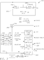
- FIG. 2 is a schematic block diagram of a thermal management system (TMS) 200 in accordance with an exemplary embodiment of the present invention.
- TMS 200 includes a heat transfer loop 202 that gathers waste heat from aircraft engine 20 and distributes this heat to locations where heating is needed.
- TMS 200 provides thermal energy to many areas which would otherwise use electrical power for electric heaters.
- waste heat instead of electric heat facilitates improving the overall efficiency of aircraft 10. Electrical system efficiency is improved by operation at a higher average percentage of full load.
- TMS 200 includes an engine heat exchanger 204 configured to transfer waste heat from propulsive aircraft engine 20 to a pumped heat transfer fluid circulating through heat transfer loop 202.
- engine heat exchanger 204 may be embodied in a lube oil cooler or other heat exchanger configured to remove waste heat from engine 20 and transfer it to the heat transfer fluid.
- TMS 200 also includes an engine exhaust heat exchanger 206 coupled in flow communication with engine heat exchanger 204.
- Engine exhaust heat exchanger 206 is configured to transfer heat from an exhaust (not shown) of propulsive aircraft engine 20 to the pumped heat transfer fluid when additional heat is required.
- engine exhaust heat exchanger 206 is coupled in serial flow communication with engine heat exchanger 204.
- a bypass valve 208 is coupled in parallel with engine exhaust heat exchanger 206 and is selectable to modulate a flow of the pumped heat transfer fluid through engine exhaust heat exchanger 206 in response to a demand for more or less heat.
- TMS 200 also includes a plurality of accessory heat exchangers for each of a plurality of heat loads of aircraft 10 coupled in flow communication with at least one of engine heat exchanger 204 and engine exhaust heat exchanger 206.
- a flow through one or more of the plurality of accessory heat exchangers is controllable using an associated modulating valve or a plurality of heat exchangers may be ganged together and controlled by a single modulating valve.
- heat for use by TMS 200 is recovered from cooling oil of engine 20. Cooling the oil, in turn cools engine 20, a gearbox 210, and accessories including the aircraft electrical generators 212.
- the heating oil is pumped by a heat transfer fluid pump 214 coupled in flow communication with the plurality of accessory heat exchangers, which include, for example, but not limited to, a nacelle anti-ice heat exchanger 216, a wing anti-ice heat exchanger 218, a cargo bay heating heat exchanger 220, and a cabin air heater heat exchanger 222.
- TMS 200 includes a modulating valve associated with each heat exchanger.
- Nacelle modulating valve 226 is associated with nacelle anti-ice heat exchanger 216
- a wing modulating valve 228 is associated with wing anti-ice heat exchanger 2118
- a cargo bay heating modulating valve 230 is associated with cargo bay heating heat exchanger 220
- a cabin air heater modulating valve 232 is associated with cabin air heater heat exchanger 222.
- TMS 200 includes a cabin air compressor heat removal system 234 configured to transmit heat from a cabin air compressor 236 to a cabin 236 of aircraft 10. More electric airplanes have large cabin air compressors, for example, which need considerable cooling for the motor controller, the electric motor, the compressor, and the exit air, which may be too warm for passenger comfort.
- cabin air compressor heat removal system 234 is configured to transmit heat from cabin air compressor 236 to an environmental control system 238.
- TMS 200 includes a mixing valve 240 configured to mix conditioned air from cabin air compressor heat removal system 234 and cabin air heater heat exchanger 222 to provide conditioned air to cabin 244.
- TMS 200 directs warm flowing fluid to surfaces requiring anti-ice including the engine nacelle, the wing leading edges, and horizontal stabilizers. There are some flight conditions where additional cabin heating is required, so cabin air heater heat exchanger 222 is included. There may be a need for cargo bay heating or heating of other non-conditioned areas; TMS 200 can accommodate these also.
- Heat transfer fluid pump 214 is an electric motor driven fluid pump which circulates a heat transfer fluid, such as, a water/propylene glycol mixture around heat transfer loop 202.
- the heat transfer fluid first passes through engine heat exchanger 204 to cool the oil to a suitable temperature for lubrication of engine 20 and engine driven accessories that are cooled rejecting heat to the engine lubricating oil.
- engine driven fuel pumps typically include engine driven fuel pumps, aircraft electrical generators 212, emergency power generators and emergency hydraulic pumps, with the result that essentially all of the accessories waste heat ends up in the lube oil and is transferred to heat transfer loop 202.
- bypass valve 208 is opened, routing heat transfer fluid around engine exhaust heat exchanger 206. If the heat transfer fluid temperature exiting engine heat exchanger 204 is too low, bypass valve 208 is closed as necessary to route some or all of the heat transfer fluid through the engine exhaust heat exchanger 206.
- bypass valve 208 is adjusted continuously to maintain a constant heat transfer fluid outlet temperature after the bypassed fluid and fluid routed through the engine exhaust heat exchanger mixes. This control approach provides a constant heat transfer fluid temperature to the downstream devices requiring heating.
- Warm mixed fluid is then directed to all of the devices to be heated in a parallel flow arrangement so that each user can operate independently, taking the heat it requires.
- the modulating valve for each of the parallel loops may be a simple on/off valve that is turned on when heating is required. It can also be a modulating valve that adjusts the flow rate to maintain constant heating rate or constant fluid outlet temperatures or other heating parameter that is appropriate for the device.
- Another way to control the fluid flow to a particular device is to pulse an on/off valve at a variable duty cycle to get the effect of a modulating valve with a simpler on/off valve.
- Fluid exiting the parallel loops rejoins the main loop and is directed to an inlet 242 of heat transfer fluid pump 214, where the heat collecting process repeats.
- Heat transfer loop 202 could be routed to devices such as this to capture their waste heat, avoiding a separate cooling loop in many cases.
- thermal management loop it may be desirable to arrange multiple loops, each at a different temperature. Electronics typically require a relatively low temperature for heat pickup, and a similar low temperature is used for passenger comfort while heating the cabin.
- the electronics cooling loop may therefore be separate from a higher temperature loop, which cools lube oil and heats the leading edge of the wing to provide wing anti-icing.
- the above-described embodiments of a method and system of thermal management provides a cost-effective and reliable means of using waste heat to perform heating tasks that would otherwise be provided by wasteful electrical heaters. More specifically, the methods and systems described herein facilitate enhancing the more electric aircraft by reducing the size of the electrical system and improving the electrical system efficiency. In addition, study results have shown that the more electric aircraft reduces aircraft fuel consumption. The TMS facilitates providing an additional reduction in aircraft fuel consumption. As a result, the methods and systems described herein facilitate operating an aircraft or other vehicle in a cost-effective and reliable manner.
Landscapes
- Engineering & Computer Science (AREA)
- Aviation & Aerospace Engineering (AREA)
- Health & Medical Sciences (AREA)
- General Health & Medical Sciences (AREA)
- Pulmonology (AREA)
- Air-Conditioning For Vehicles (AREA)
Description
- The field of the invention relates generally to vehicle thermal management, and more specifically, to a method and systems for managing waste heat and supplying heat to various loads in an aircraft.
- Aircraft of the type known as "more electric aircraft" are using electric heating for anti-icing. The anti-ice electric loads are high, causing the need for the aircraft electrical system to be oversized in order to accommodate these high electrical loads. This results in excessive weight of the electrical generation and distribution system, excessive engine power extraction, and reduced electrical system efficiency during most of the flight, when anti-ice is not required.
- At least some known have used engine bleed air to pressurize the cabin, power the air cycle environmental control system (ECS), and heat the leading edges of the wings and tail to prevent ice formation. Aircraft manufacturers are, moving toward more electric power and away from hydraulic and bleed air. In some cases, bleed air is eliminated, entirely, with these functions being replaced by electrically powered components. The "more electric aircraft" provides cabin air via an electric motor-driven compressor. A vapor cycle ECS provides cabin cooling as needed for passenger and crew comfort. The anti-ice functions are performed by electric heaters. These heaters consume a large portion of the total aircraft electrical power, even though they are used for only a small portion of a typical flight. The anti-ice electrical power requirements are a major factor in sizing of the aircraft generators, adding considerable weight to the electrical generating and distribution system. The generators are oversized for the loads encountered during the major portion of the flight and operate less efficiently than they would if anti-ice were provided by another means.
-
US 2004/144084 A1 discloses an exhaust-heat recovery system which comprises a catalytic converter, an exhaust heat exchanger, an air conditioner and an engine controller. -
US 2003/150955 A1 discloses a heat exchanger system and method for heating selected areas of the wings of an aircraft. - In one embodiment, there is provided an aircraft according to claim 1.
- In another embodiment, there is provided a method of anti-icing using a thermal management system (TMS) according to claim 3.
-
-
Figures 1-2 show exemplary embodiments of the method and system described herein. -
Figure 1 is a perspective view of an aircraft in accordance with an exemplary embodiment of the present invention; and -
Figure 2 is a schematic block diagram of a thermal management system (TMS) in accordance with an exemplary embodiment of the present invention. - The following detailed description illustrates embodiments of the invention by way of example and not by way of limitation. It is contemplated that the invention has general application to sub-systems and methodical processes that manage thermal energy to improve an overall efficiency of a system in industrial, commercial, and residential applications.
- As used herein, an element or step recited in the singular and proceeded with the word "a" or "an" should be understood as not excluding plural elements or steps, unless such exclusion is explicitly recited. Furthermore, references to "one embodiment" of the present invention are not intended to be interpreted as excluding the existence of additional embodiments that also incorporate the recited features.
-
Figure 1 is a perspective view of anaircraft 10 in accordance with an exemplary embodiment of the present invention. In the exemplary embodiment,aircraft 10 includes afuselage 12,wings 14,horizontal stabilizers 16, avertical stabilizer 18,aircraft engines 20, andpylons 22. Wings 14 are primary lift providers foraircraft 10.Horizontal stabilizers 16 facilitate preventing an up-down motion of the aircraft nose, andvertical stabilizer 18 facilitates preventing side to side swinging.Engines 20 provide thrust foraircraft 10 andpylons 22 serve as underwing mounts for the engines. -
Figure 2 is a schematic block diagram of a thermal management system (TMS) 200 in accordance with an exemplary embodiment of the present invention. In the exemplary embodiment, TMS 200 includes aheat transfer loop 202 that gathers waste heat fromaircraft engine 20 and distributes this heat to locations where heating is needed. TMS 200 provides thermal energy to many areas which would otherwise use electrical power for electric heaters. - Using waste heat instead of electric heat facilitates improving the overall efficiency of
aircraft 10. Electrical system efficiency is improved by operation at a higher average percentage of full load. - TMS 200 includes an
engine heat exchanger 204 configured to transfer waste heat frompropulsive aircraft engine 20 to a pumped heat transfer fluid circulating throughheat transfer loop 202. In various embodiments,engine heat exchanger 204 may be embodied in a lube oil cooler or other heat exchanger configured to remove waste heat fromengine 20 and transfer it to the heat transfer fluid. TMS 200 also includes an engineexhaust heat exchanger 206 coupled in flow communication withengine heat exchanger 204. Engineexhaust heat exchanger 206 is configured to transfer heat from an exhaust (not shown) ofpropulsive aircraft engine 20 to the pumped heat transfer fluid when additional heat is required. In one embodiment, engineexhaust heat exchanger 206 is coupled in serial flow communication withengine heat exchanger 204. Abypass valve 208 is coupled in parallel with engineexhaust heat exchanger 206 and is selectable to modulate a flow of the pumped heat transfer fluid through engineexhaust heat exchanger 206 in response to a demand for more or less heat. TMS 200 also includes a plurality of accessory heat exchangers for each of a plurality of heat loads ofaircraft 10 coupled in flow communication with at least one ofengine heat exchanger 204 and engineexhaust heat exchanger 206. A flow through one or more of the plurality of accessory heat exchangers is controllable using an associated modulating valve or a plurality of heat exchangers may be ganged together and controlled by a single modulating valve. - In the exemplary embodiment, heat for use by TMS 200 is recovered from cooling oil of
engine 20. Cooling the oil, in turncools engine 20, agearbox 210, and accessories including the aircraftelectrical generators 212. - The heating oil is pumped by a heat
transfer fluid pump 214 coupled in flow communication with the plurality of accessory heat exchangers, which include, for example, but not limited to, a nacelleanti-ice heat exchanger 216, a winganti-ice heat exchanger 218, a cargo bayheating heat exchanger 220, and a cabin airheater heat exchanger 222. In the exemplary embodiment, TMS 200 includes a modulating valve associated with each heat exchanger. Nacelle modulatingvalve 226 is associated with nacelleanti-ice heat exchanger 216, awing modulating valve 228 is associated with winganti-ice heat exchanger 218, a cargo bayheating modulating valve 230 is associated with cargo bayheating heat exchanger 220, and a cabin airheater modulating valve 232 is associated with cabin airheater heat exchanger 222. - In the exemplary embodiment, TMS 200 includes a cabin air compressor
heat removal system 234 configured to transmit heat from acabin air compressor 236 to acabin 236 ofaircraft 10. More electric airplanes have large cabin air compressors, for example, which need considerable cooling for the motor controller, the electric motor, the compressor, and the exit air, which may be too warm for passenger comfort. In another embodiment, cabin air compressorheat removal system 234 is configured to transmit heat fromcabin air compressor 236 to anenvironmental control system 238. In various embodiments, TMS 200 includes amixing valve 240 configured to mix conditioned air from cabin air compressorheat removal system 234 and cabin airheater heat exchanger 222 to provide conditioned air tocabin 244. - TMS 200 directs warm flowing fluid to surfaces requiring anti-ice including the engine nacelle, the wing leading edges, and horizontal stabilizers. There are some flight conditions where additional cabin heating is required, so cabin air
heater heat exchanger 222 is included. There may be a need for cargo bay heating or heating of other non-conditioned areas; TMS 200 can accommodate these also. - Heat
transfer fluid pump 214 is an electric motor driven fluid pump which circulates a heat transfer fluid, such as, a water/propylene glycol mixture aroundheat transfer loop 202. - During operation, the heat transfer fluid first passes through
engine heat exchanger 204 to cool the oil to a suitable temperature for lubrication ofengine 20 and engine driven accessories that are cooled rejecting heat to the engine lubricating oil. These accessories typically include engine driven fuel pumps, aircraftelectrical generators 212, emergency power generators and emergency hydraulic pumps, with the result that essentially all of the accessories waste heat ends up in the lube oil and is transferred toheat transfer loop 202. - There may be situations where this lube oil waste heat is sufficient to provide all of the heating needs of the remainder of
heat transfer loop 202. In this case, no additional heat gain is required andbypass valve 208 is opened, routing heat transfer fluid around engineexhaust heat exchanger 206. If the heat transfer fluid temperature exitingengine heat exchanger 204 is too low,bypass valve 208 is closed as necessary to route some or all of the heat transfer fluid through the engineexhaust heat exchanger 206. - In one embodiment,
bypass valve 208 is adjusted continuously to maintain a constant heat transfer fluid outlet temperature after the bypassed fluid and fluid routed through the engine exhaust heat exchanger mixes. This control approach provides a constant heat transfer fluid temperature to the downstream devices requiring heating. - Warm mixed fluid is then directed to all of the devices to be heated in a parallel flow arrangement so that each user can operate independently, taking the heat it requires.
- The modulating valve for each of the parallel loops may be a simple on/off valve that is turned on when heating is required. It can also be a modulating valve that adjusts the flow rate to maintain constant heating rate or constant fluid outlet temperatures or other heating parameter that is appropriate for the device.
- Another way to control the fluid flow to a particular device is to pulse an on/off valve at a variable duty cycle to get the effect of a modulating valve with a simpler on/off valve.
- Fluid exiting the parallel loops rejoins the main loop and is directed to an
inlet 242 of heattransfer fluid pump 214, where the heat collecting process repeats. - There may be other sources of waste heat on the aircraft that could easily be cooled with
heat transfer loop 202.Heat transfer loop 202 could be routed to devices such as this to capture their waste heat, avoiding a separate cooling loop in many cases. - If many sources and sinks of heat can benefit from a thermal management loop, it may be desirable to arrange multiple loops, each at a different temperature. Electronics typically require a relatively low temperature for heat pickup, and a similar low temperature is used for passenger comfort while heating the cabin. The electronics cooling loop may therefore be separate from a higher temperature loop, which cools lube oil and heats the leading edge of the wing to provide wing anti-icing.
- The above-described embodiments of a method and system of thermal management provides a cost-effective and reliable means of using waste heat to perform heating tasks that would otherwise be provided by wasteful electrical heaters. More specifically, the methods and systems described herein facilitate enhancing the more electric aircraft by reducing the size of the electrical system and improving the electrical system efficiency. In addition, study results have shown that the more electric aircraft reduces aircraft fuel consumption. The TMS facilitates providing an additional reduction in aircraft fuel consumption. As a result, the methods and systems described herein facilitate operating an aircraft or other vehicle in a cost-effective and reliable manner.
- Exemplary methods and system for managing thermal energy in a vehicle are described above in detail. The apparatus illustrated is not limited to the specific embodiments described herein, but rather, components of each may be utilized independently and separately from other components described herein. Each system component can also be used in combination with other system components.
- This written description uses examples to disclose the invention, including the best mode, and also to enable any person skilled in the art to practice the invention, including making and using any devices or systems and performing any incorporated methods. The patentable scope of the invention is defined by the claims, and may include other examples that occur to those skilled in the art. Such other examples are intended to be within the scope of the claims if they have structural elements that do not differ from the literal language of the claims, or if they include equivalent structural elements with insubstantial differences from the literal languages of the claims.
Claims (6)
- An aircraft (10) comprising:an engine (20) including a nacelle and an exhaust, said nacelle comprising a nacelle anti-icing heat exchanger (216);a wing (14) comprising a wing anti-icing heat exchanger (218);a cargo bay comprising a cargo bay heat exchanger (220); anda thermal management system (200) comprising:an engine heat exchanger (204) configured to channel a flow of lube oil therethrough, the flow of lube oil coupled in thermal communication with said engine (20) and with engine driven accessories such that excess heat generated therefrom is recovered by the lube oil; anda fluid pump (214) coupled in flow communication between said engine heat exchanger and at least one of said nacelle anti-icing heat exchanger, said wing anti-icing heat exchanger (218), and said cargo bay heat exchanger (220), said fluid pump configured to pump heat transfer fluid through said engine heat exchanger such that the excess heat is transferred from the lube oil to the heat transfer fluid, wherein the heat transfer fluid carries the excess heat towards at least one of said nacelle anti-icing heat exchanger, said wing anti-icing heat exchanger, and said cargo bay heat exchanger; characterized in that it further comprisesan engine exhaust heat exchanger (206) coupled in thermal communication with a portion of the engine exhaust and coupled in flow communication to said engine heat exchanger (204) and at least one of said nacelle anti-icing heat exchanger (216), said wing anti-icing heat exchanger (218), and said cargo bay heat exchanger (220).
- An aircraft (10) in accordance with claim 1, wherein the system (200) further comprises an engine exhaust heat exchanger bypass valve (208) coupled in parallel flow with said engine exhaust heat exchanger (206), said bypass valve configured to be controlled to maintain a predetermined temperature of fluid downstream of said engine exhaust heat exchanger.
- A method of anti-icing using a thermal management system (TMS) (200) comprising:positioning an engine heat exchanger (204) in thermal communication with a heat transfer fluid;recovering waste heat conducted from an engine (20) and from engine driven accessories of a vehicle, the waste heat recovered by a flow of lube oil flowing through the engine heat exchanger;channeling the heat transfer fluid and the flow of lube oil through the engine heat exchanger such that the recovered waste heat is transferred from the flow of lube oil to the heat transfer fluid;pumping (214) the heat transfer fluid carrying the recovered waste heat from the heat exchanger to a heat load of the vehicle coupled in fluid communication with the heat exchanger; andtransferring the recovered heat from the heat transfer fluid to the heat load,characterized in that recovering waste heat comprises recovering waste heat from an engine exhaust heat exchanger (206) positioned at least one of in an exhaust stream of the engine and proximate the exhaust stream of the engine.
- A method in accordance with claim 3, further comprising bypassing the pumped heat transfer fluid around the engine exhaust heat exchanger (206) using a bypass valve (208).
- A method in accordance with claim 4, further comprising maintaining a substantially constant temperature of the heat transfer fluid downstream of the engine exhaust heat exchanger using the bypass valve (208).
- A method in accordance with any one of claims 3 to 5, wherein pumping a heat transfer fluid comprises pumping a heat transfer fluid carrying the recovered waste heat to at least one of a plurality of heat loads.
Applications Claiming Priority (1)
| Application Number | Priority Date | Filing Date | Title |
|---|---|---|---|
| US12/870,947 US9114877B2 (en) | 2010-08-30 | 2010-08-30 | Method and system for vehicle thermal management |
Publications (3)
| Publication Number | Publication Date |
|---|---|
| EP2423106A2 EP2423106A2 (en) | 2012-02-29 |
| EP2423106A3 EP2423106A3 (en) | 2017-07-12 |
| EP2423106B1 true EP2423106B1 (en) | 2019-07-17 |
Family
ID=44658642
Family Applications (1)
| Application Number | Title | Priority Date | Filing Date |
|---|---|---|---|
| EP11178268.6A Active EP2423106B1 (en) | 2010-08-30 | 2011-08-22 | Method and system for vehicle thermal management |
Country Status (5)
| Country | Link |
|---|---|
| US (1) | US9114877B2 (en) |
| EP (1) | EP2423106B1 (en) |
| CN (1) | CN102407944B (en) |
| BR (1) | BRPI1104069A2 (en) |
| CA (1) | CA2749471C (en) |
Families Citing this family (32)
| Publication number | Priority date | Publication date | Assignee | Title |
|---|---|---|---|---|
| US10488075B2 (en) | 2013-06-18 | 2019-11-26 | B/E Aerospace, Inc. | Apparatus for pre-heating potable water in aircraft with waste heat |
| FR3027624B1 (en) * | 2014-10-27 | 2019-04-19 | Safran Aircraft Engines | CIRCUIT FOR DEFROSTING AIR INLET LIP FROM A PROPELLANT AIRCRAFT ASSEMBLY |
| US10100733B2 (en) | 2015-07-31 | 2018-10-16 | Ge Aviation Systems Llc | Turbine engine with anti-ice valve assembly, bleed air valve, and method of operating |
| US10260419B2 (en) * | 2015-07-31 | 2019-04-16 | General Electric Company | Cooling system |
| US10144521B2 (en) | 2015-08-04 | 2018-12-04 | Hamilton Sundstrand Corporation | Electric compressor for use with a wing anti-ice system |
| US10041375B2 (en) | 2015-11-10 | 2018-08-07 | General Electric Company | Apparatus for oil collection and heat exchanging for turbine engines |
| US10823066B2 (en) * | 2015-12-09 | 2020-11-03 | General Electric Company | Thermal management system |
| US11125160B2 (en) * | 2015-12-28 | 2021-09-21 | General Electric Company | Method and system for combination heat exchanger |
| US10544717B2 (en) | 2016-09-07 | 2020-01-28 | Pratt & Whitney Canada Corp. | Shared oil system arrangement for an engine component and a generator |
| US20180229850A1 (en) * | 2017-02-15 | 2018-08-16 | Pratt & Whitney Canada Corp. | Anti-icing system for gas turbine engine |
| US10696412B2 (en) * | 2017-09-29 | 2020-06-30 | The Boeing Company | Combined fluid ice protection and electronic cooling system |
| US20190257569A1 (en) * | 2018-02-19 | 2019-08-22 | Hamilton Sundstrand Corporation | Closed loop icing control for heat exchangers |
| US10710741B2 (en) | 2018-07-02 | 2020-07-14 | Joby Aero, Inc. | System and method for airspeed determination |
| EP3853736B1 (en) | 2018-09-17 | 2025-10-22 | Joby Aero, Inc. | Aircraft control system |
| US11146146B2 (en) | 2018-11-13 | 2021-10-12 | General Electric Company | Apparatus and method for cooling endwindings in a rotating electric machine |
| EP3891067B1 (en) | 2018-12-07 | 2024-01-17 | Joby Aero, Inc. | Aircraft control system and method |
| US11230384B2 (en) * | 2019-04-23 | 2022-01-25 | Joby Aero, Inc. | Vehicle cabin thermal management system and method |
| CN114041229B (en) | 2019-04-23 | 2023-06-16 | 杰欧比飞行有限公司 | Battery thermal management system and method |
| CN111516882B (en) * | 2020-05-14 | 2022-03-22 | 中国商用飞机有限责任公司 | Heating and ventilation systems for aircraft cabins |
| US11434824B2 (en) | 2021-02-03 | 2022-09-06 | General Electric Company | Fuel heater and energy conversion system |
| US11591965B2 (en) | 2021-03-29 | 2023-02-28 | General Electric Company | Thermal management system for transferring heat between fluids |
| US12116929B2 (en) | 2022-01-19 | 2024-10-15 | General Electric Company | Bleed flow assembly for a gas turbine engine |
| US11788465B2 (en) | 2022-01-19 | 2023-10-17 | General Electric Company | Bleed flow assembly for a gas turbine engine |
| US11808281B2 (en) | 2022-03-04 | 2023-11-07 | General Electric Company | Gas turbine engine with variable pitch inlet pre-swirl features |
| CN115783267B (en) * | 2022-11-17 | 2025-12-19 | 中国直升机设计研究所 | Passive helicopter cabin heating system utilizing lubricating oil waste heat |
| US12209557B1 (en) | 2023-11-30 | 2025-01-28 | General Electric Company | Gas turbine engine with forward swept outlet guide vanes |
| US12385430B2 (en) | 2023-11-30 | 2025-08-12 | General Electric Company | Gas turbine engine with forward swept outlet guide vanes |
| US12228037B1 (en) | 2023-12-04 | 2025-02-18 | General Electric Company | Guide vane assembly with fixed and variable pitch inlet guide vanes |
| US12313021B1 (en) | 2024-03-14 | 2025-05-27 | General Electric Company | Outer nacelle with inlet guide vanes and acoustic treatment |
| DE102025122365A1 (en) * | 2024-06-12 | 2025-12-18 | Eaton Intelligent Power Limited | ICE PROTECTION SYSTEM WITH WASTE HEAT RECOVERY |
| US12428988B1 (en) | 2024-08-16 | 2025-09-30 | General Electric Company | High temperature anti-ice systems for aircraft engines |
| US12435668B1 (en) | 2024-11-01 | 2025-10-07 | General Electric Company | Methods and apparatus for anti-ice heat supply from waste heat recovery systems |
Family Cites Families (23)
| Publication number | Priority date | Publication date | Assignee | Title |
|---|---|---|---|---|
| US3711044A (en) * | 1971-03-17 | 1973-01-16 | Garrett Corp | Automatic interface control system |
| US3981466A (en) * | 1974-12-23 | 1976-09-21 | The Boeing Company | Integrated thermal anti-icing and environmental control system |
| US5222696A (en) * | 1986-10-30 | 1993-06-29 | Zwick Energy Research Organization, Inc. | Flameless deicer |
| US5098036A (en) * | 1986-10-30 | 1992-03-24 | Zwick Energy Research Organization, Inc. | Flameless deicer |
| US4782658A (en) * | 1987-05-07 | 1988-11-08 | Rolls-Royce Plc | Deicing of a geared gas turbine engine |
| US5143329A (en) * | 1990-06-01 | 1992-09-01 | General Electric Company | Gas turbine engine powered aircraft environmental control system and boundary layer bleed |
| US5228643A (en) * | 1992-06-25 | 1993-07-20 | Mcdonnell Douglas Corporation | Energy-exchange system incorporating small-diameter tubes |
| US5484122A (en) | 1993-11-09 | 1996-01-16 | Parker-Hannifin Corporation | Turbine exhaust gas anti-ice system |
| US5490645A (en) * | 1993-12-09 | 1996-02-13 | Allied-Signal Inc. | Fully integrated environmental and secondary power system |
| US5558303A (en) * | 1994-12-27 | 1996-09-24 | Koethe; Terence L. | Method and apparatus for using hot fuels to de-ice aircraft |
| US5813630A (en) * | 1996-09-27 | 1998-09-29 | Mcdonnell Douglas Corporation | Multi-mode secondary power unit |
| JP3807637B2 (en) * | 1996-10-09 | 2006-08-09 | エス・ティ・エス株式会社 | Deicing device |
| US6305156B1 (en) | 1999-09-03 | 2001-10-23 | Alliedsignal Inc. | Integrated bleed air and engine starting system |
| AU2002235116A1 (en) * | 2000-08-18 | 2002-05-15 | Goodrich Corporation | Aircraft supplemental air heater |
| US6460353B2 (en) | 2001-03-02 | 2002-10-08 | Honeywell International Inc. | Method and apparatus for improved aircraft environmental control system utilizing parallel heat exchanger arrays |
| US6817575B1 (en) * | 2001-09-20 | 2004-11-16 | Hamilton Sundstrand Corporation | Integrated system for providing aircraft environmental control |
| US6663044B1 (en) * | 2001-09-20 | 2003-12-16 | Hamilton Sundstrand Corporation | Vapor compression cycle environmental control system |
| US6698687B2 (en) * | 2002-02-13 | 2004-03-02 | The Boeing Company | Aircraft wing heat exchanger apparatus and method |
| JP4157752B2 (en) * | 2002-11-19 | 2008-10-01 | カルソニックカンセイ株式会社 | Engine exhaust heat recovery device |
| GB0311663D0 (en) * | 2003-05-21 | 2003-06-25 | Rolls Royce Plc | Aeroengine intake |
| US7171819B2 (en) | 2005-01-21 | 2007-02-06 | Honeywell International, Inc. | Indirect regenerative air cycle for integrated power and cooling machines |
| JP4627210B2 (en) | 2005-04-01 | 2011-02-09 | 株式会社デンソー | Exhaust heat recovery device and control method thereof |
| US7305842B1 (en) | 2005-05-23 | 2007-12-11 | Peter Schiff | Environmental control system and method for an aircraft |
-
2010
- 2010-08-30 US US12/870,947 patent/US9114877B2/en active Active
-
2011
- 2011-08-12 BR BRPI1104069-6A patent/BRPI1104069A2/en active Search and Examination
- 2011-08-18 CA CA2749471A patent/CA2749471C/en not_active Expired - Fee Related
- 2011-08-22 EP EP11178268.6A patent/EP2423106B1/en active Active
- 2011-08-30 CN CN201110269992.4A patent/CN102407944B/en active Active
Non-Patent Citations (1)
| Title |
|---|
| None * |
Also Published As
| Publication number | Publication date |
|---|---|
| EP2423106A3 (en) | 2017-07-12 |
| CN102407944A (en) | 2012-04-11 |
| US20120048509A1 (en) | 2012-03-01 |
| BRPI1104069A2 (en) | 2013-03-19 |
| CA2749471A1 (en) | 2012-02-29 |
| US9114877B2 (en) | 2015-08-25 |
| CN102407944B (en) | 2016-03-02 |
| CA2749471C (en) | 2018-08-14 |
| EP2423106A2 (en) | 2012-02-29 |
Similar Documents
| Publication | Publication Date | Title |
|---|---|---|
| US9114877B2 (en) | Method and system for vehicle thermal management | |
| US11591102B2 (en) | Aircraft with thermal energy storage system for multiple heat loads | |
| US7207521B2 (en) | Electric-based secondary power system architectures for aircraft | |
| EP1557357B1 (en) | Thermal management system for an aircraft | |
| EP3279091B1 (en) | Aircraft electronics thermal regulation system | |
| US6698687B2 (en) | Aircraft wing heat exchanger apparatus and method | |
| EP1762491A2 (en) | Deoxygenated fuel-cooler environmental control system pre-cooler for an aircraft | |
| US20100288244A1 (en) | Method for controlling thermal effluents generated by an aircraft and cooling device for an aircraft implementing said method | |
| US10501191B1 (en) | Integrated aircraft cooling machine | |
| EP3085623B1 (en) | Modular environmental air conditioning system | |
| CN107709161B (en) | Hybrid electric power | |
| EP3241757A1 (en) | Fuel tank inerting systems for aircraft | |
| US20230323816A1 (en) | Aircraft with thermal energy storage system with bypass control | |
| Seki et al. | A study of air/fuel integrated thermal management system | |
| EP2915746A1 (en) | Aircraft air conditioning system and method of operating an aircraft air conditioning system | |
| ES2824518T3 (en) | Power grid and shared power distribution method on board an aircraft | |
| Morioka et al. | All electric system architecture for aircraft and propulsion |
Legal Events
| Date | Code | Title | Description |
|---|---|---|---|
| AK | Designated contracting states |
Kind code of ref document: A2 Designated state(s): AL AT BE BG CH CY CZ DE DK EE ES FI FR GB GR HR HU IE IS IT LI LT LU LV MC MK MT NL NO PL PT RO RS SE SI SK SM TR |
|
| AX | Request for extension of the european patent |
Extension state: BA ME |
|
| PUAI | Public reference made under article 153(3) epc to a published international application that has entered the european phase |
Free format text: ORIGINAL CODE: 0009012 |
|
| RTI1 | Title (correction) |
Free format text: METHOD AND SYSTEM FOR VEHICLE THERMAL MANAGEMENT |
|
| PUAL | Search report despatched |
Free format text: ORIGINAL CODE: 0009013 |
|
| AK | Designated contracting states |
Kind code of ref document: A3 Designated state(s): AL AT BE BG CH CY CZ DE DK EE ES FI FR GB GR HR HU IE IS IT LI LT LU LV MC MK MT NL NO PL PT RO RS SE SI SK SM TR |
|
| AX | Request for extension of the european patent |
Extension state: BA ME |
|
| RIC1 | Information provided on ipc code assigned before grant |
Ipc: B64D 13/00 20060101ALI20170607BHEP Ipc: B64D 11/00 20060101AFI20170607BHEP Ipc: B64D 15/04 20060101ALI20170607BHEP Ipc: B64D 33/02 20060101ALN20170607BHEP Ipc: B64D 13/06 20060101ALN20170607BHEP |
|
| STAA | Information on the status of an ep patent application or granted ep patent |
Free format text: STATUS: REQUEST FOR EXAMINATION WAS MADE |
|
| 17P | Request for examination filed |
Effective date: 20180112 |
|
| RBV | Designated contracting states (corrected) |
Designated state(s): AL AT BE BG CH CY CZ DE DK EE ES FI FR GB GR HR HU IE IS IT LI LT LU LV MC MK MT NL NO PL PT RO RS SE SI SK SM TR |
|
| STAA | Information on the status of an ep patent application or granted ep patent |
Free format text: STATUS: EXAMINATION IS IN PROGRESS |
|
| 17Q | First examination report despatched |
Effective date: 20180627 |
|
| GRAP | Despatch of communication of intention to grant a patent |
Free format text: ORIGINAL CODE: EPIDOSNIGR1 |
|
| STAA | Information on the status of an ep patent application or granted ep patent |
Free format text: STATUS: GRANT OF PATENT IS INTENDED |
|
| INTG | Intention to grant announced |
Effective date: 20190207 |
|
| GRAS | Grant fee paid |
Free format text: ORIGINAL CODE: EPIDOSNIGR3 |
|
| GRAA | (expected) grant |
Free format text: ORIGINAL CODE: 0009210 |
|
| STAA | Information on the status of an ep patent application or granted ep patent |
Free format text: STATUS: THE PATENT HAS BEEN GRANTED |
|
| AK | Designated contracting states |
Kind code of ref document: B1 Designated state(s): AL AT BE BG CH CY CZ DE DK EE ES FI FR GB GR HR HU IE IS IT LI LT LU LV MC MK MT NL NO PL PT RO RS SE SI SK SM TR |
|
| REG | Reference to a national code |
Ref country code: GB Ref legal event code: FG4D |
|
| REG | Reference to a national code |
Ref country code: CH Ref legal event code: EP |
|
| REG | Reference to a national code |
Ref country code: DE Ref legal event code: R096 Ref document number: 602011060459 Country of ref document: DE |
|
| REG | Reference to a national code |
Ref country code: IE Ref legal event code: FG4D |
|
| REG | Reference to a national code |
Ref country code: AT Ref legal event code: REF Ref document number: 1155631 Country of ref document: AT Kind code of ref document: T Effective date: 20190815 |
|
| REG | Reference to a national code |
Ref country code: NL Ref legal event code: MP Effective date: 20190717 |
|
| REG | Reference to a national code |
Ref country code: LT Ref legal event code: MG4D |
|
| REG | Reference to a national code |
Ref country code: AT Ref legal event code: MK05 Ref document number: 1155631 Country of ref document: AT Kind code of ref document: T Effective date: 20190717 |
|
| PG25 | Lapsed in a contracting state [announced via postgrant information from national office to epo] |
Ref country code: NL Free format text: LAPSE BECAUSE OF FAILURE TO SUBMIT A TRANSLATION OF THE DESCRIPTION OR TO PAY THE FEE WITHIN THE PRESCRIBED TIME-LIMIT Effective date: 20190717 Ref country code: AT Free format text: LAPSE BECAUSE OF FAILURE TO SUBMIT A TRANSLATION OF THE DESCRIPTION OR TO PAY THE FEE WITHIN THE PRESCRIBED TIME-LIMIT Effective date: 20190717 Ref country code: SE Free format text: LAPSE BECAUSE OF FAILURE TO SUBMIT A TRANSLATION OF THE DESCRIPTION OR TO PAY THE FEE WITHIN THE PRESCRIBED TIME-LIMIT Effective date: 20190717 Ref country code: LT Free format text: LAPSE BECAUSE OF FAILURE TO SUBMIT A TRANSLATION OF THE DESCRIPTION OR TO PAY THE FEE WITHIN THE PRESCRIBED TIME-LIMIT Effective date: 20190717 Ref country code: BG Free format text: LAPSE BECAUSE OF FAILURE TO SUBMIT A TRANSLATION OF THE DESCRIPTION OR TO PAY THE FEE WITHIN THE PRESCRIBED TIME-LIMIT Effective date: 20191017 Ref country code: PT Free format text: LAPSE BECAUSE OF FAILURE TO SUBMIT A TRANSLATION OF THE DESCRIPTION OR TO PAY THE FEE WITHIN THE PRESCRIBED TIME-LIMIT Effective date: 20191118 Ref country code: HR Free format text: LAPSE BECAUSE OF FAILURE TO SUBMIT A TRANSLATION OF THE DESCRIPTION OR TO PAY THE FEE WITHIN THE PRESCRIBED TIME-LIMIT Effective date: 20190717 Ref country code: FI Free format text: LAPSE BECAUSE OF FAILURE TO SUBMIT A TRANSLATION OF THE DESCRIPTION OR TO PAY THE FEE WITHIN THE PRESCRIBED TIME-LIMIT Effective date: 20190717 Ref country code: NO Free format text: LAPSE BECAUSE OF FAILURE TO SUBMIT A TRANSLATION OF THE DESCRIPTION OR TO PAY THE FEE WITHIN THE PRESCRIBED TIME-LIMIT Effective date: 20191017 |
|
| PG25 | Lapsed in a contracting state [announced via postgrant information from national office to epo] |
Ref country code: LV Free format text: LAPSE BECAUSE OF FAILURE TO SUBMIT A TRANSLATION OF THE DESCRIPTION OR TO PAY THE FEE WITHIN THE PRESCRIBED TIME-LIMIT Effective date: 20190717 Ref country code: IS Free format text: LAPSE BECAUSE OF FAILURE TO SUBMIT A TRANSLATION OF THE DESCRIPTION OR TO PAY THE FEE WITHIN THE PRESCRIBED TIME-LIMIT Effective date: 20191117 Ref country code: ES Free format text: LAPSE BECAUSE OF FAILURE TO SUBMIT A TRANSLATION OF THE DESCRIPTION OR TO PAY THE FEE WITHIN THE PRESCRIBED TIME-LIMIT Effective date: 20190717 Ref country code: AL Free format text: LAPSE BECAUSE OF FAILURE TO SUBMIT A TRANSLATION OF THE DESCRIPTION OR TO PAY THE FEE WITHIN THE PRESCRIBED TIME-LIMIT Effective date: 20190717 Ref country code: RS Free format text: LAPSE BECAUSE OF FAILURE TO SUBMIT A TRANSLATION OF THE DESCRIPTION OR TO PAY THE FEE WITHIN THE PRESCRIBED TIME-LIMIT Effective date: 20190717 Ref country code: GR Free format text: LAPSE BECAUSE OF FAILURE TO SUBMIT A TRANSLATION OF THE DESCRIPTION OR TO PAY THE FEE WITHIN THE PRESCRIBED TIME-LIMIT Effective date: 20191018 |
|
| PG25 | Lapsed in a contracting state [announced via postgrant information from national office to epo] |
Ref country code: TR Free format text: LAPSE BECAUSE OF FAILURE TO SUBMIT A TRANSLATION OF THE DESCRIPTION OR TO PAY THE FEE WITHIN THE PRESCRIBED TIME-LIMIT Effective date: 20190717 |
|
| PG25 | Lapsed in a contracting state [announced via postgrant information from national office to epo] |
Ref country code: DK Free format text: LAPSE BECAUSE OF FAILURE TO SUBMIT A TRANSLATION OF THE DESCRIPTION OR TO PAY THE FEE WITHIN THE PRESCRIBED TIME-LIMIT Effective date: 20190717 Ref country code: EE Free format text: LAPSE BECAUSE OF FAILURE TO SUBMIT A TRANSLATION OF THE DESCRIPTION OR TO PAY THE FEE WITHIN THE PRESCRIBED TIME-LIMIT Effective date: 20190717 Ref country code: RO Free format text: LAPSE BECAUSE OF FAILURE TO SUBMIT A TRANSLATION OF THE DESCRIPTION OR TO PAY THE FEE WITHIN THE PRESCRIBED TIME-LIMIT Effective date: 20190717 Ref country code: IT Free format text: LAPSE BECAUSE OF FAILURE TO SUBMIT A TRANSLATION OF THE DESCRIPTION OR TO PAY THE FEE WITHIN THE PRESCRIBED TIME-LIMIT Effective date: 20190717 Ref country code: PL Free format text: LAPSE BECAUSE OF FAILURE TO SUBMIT A TRANSLATION OF THE DESCRIPTION OR TO PAY THE FEE WITHIN THE PRESCRIBED TIME-LIMIT Effective date: 20190717 |
|
| PG25 | Lapsed in a contracting state [announced via postgrant information from national office to epo] |
Ref country code: LI Free format text: LAPSE BECAUSE OF NON-PAYMENT OF DUE FEES Effective date: 20190831 Ref country code: IS Free format text: LAPSE BECAUSE OF FAILURE TO SUBMIT A TRANSLATION OF THE DESCRIPTION OR TO PAY THE FEE WITHIN THE PRESCRIBED TIME-LIMIT Effective date: 20200224 Ref country code: MC Free format text: LAPSE BECAUSE OF FAILURE TO SUBMIT A TRANSLATION OF THE DESCRIPTION OR TO PAY THE FEE WITHIN THE PRESCRIBED TIME-LIMIT Effective date: 20190717 Ref country code: SM Free format text: LAPSE BECAUSE OF FAILURE TO SUBMIT A TRANSLATION OF THE DESCRIPTION OR TO PAY THE FEE WITHIN THE PRESCRIBED TIME-LIMIT Effective date: 20190717 Ref country code: CH Free format text: LAPSE BECAUSE OF NON-PAYMENT OF DUE FEES Effective date: 20190831 Ref country code: CZ Free format text: LAPSE BECAUSE OF FAILURE TO SUBMIT A TRANSLATION OF THE DESCRIPTION OR TO PAY THE FEE WITHIN THE PRESCRIBED TIME-LIMIT Effective date: 20190717 Ref country code: SK Free format text: LAPSE BECAUSE OF FAILURE TO SUBMIT A TRANSLATION OF THE DESCRIPTION OR TO PAY THE FEE WITHIN THE PRESCRIBED TIME-LIMIT Effective date: 20190717 Ref country code: LU Free format text: LAPSE BECAUSE OF NON-PAYMENT OF DUE FEES Effective date: 20190822 |
|
| REG | Reference to a national code |
Ref country code: BE Ref legal event code: MM Effective date: 20190831 |
|
| REG | Reference to a national code |
Ref country code: DE Ref legal event code: R097 Ref document number: 602011060459 Country of ref document: DE |
|
| PLBE | No opposition filed within time limit |
Free format text: ORIGINAL CODE: 0009261 |
|
| STAA | Information on the status of an ep patent application or granted ep patent |
Free format text: STATUS: NO OPPOSITION FILED WITHIN TIME LIMIT |
|
| PG2D | Information on lapse in contracting state deleted |
Ref country code: IS |
|
| PG25 | Lapsed in a contracting state [announced via postgrant information from national office to epo] |
Ref country code: IE Free format text: LAPSE BECAUSE OF NON-PAYMENT OF DUE FEES Effective date: 20190822 |
|
| 26N | No opposition filed |
Effective date: 20200603 |
|
| PG25 | Lapsed in a contracting state [announced via postgrant information from national office to epo] |
Ref country code: SI Free format text: LAPSE BECAUSE OF FAILURE TO SUBMIT A TRANSLATION OF THE DESCRIPTION OR TO PAY THE FEE WITHIN THE PRESCRIBED TIME-LIMIT Effective date: 20190717 Ref country code: BE Free format text: LAPSE BECAUSE OF NON-PAYMENT OF DUE FEES Effective date: 20190831 |
|
| PG25 | Lapsed in a contracting state [announced via postgrant information from national office to epo] |
Ref country code: CY Free format text: LAPSE BECAUSE OF FAILURE TO SUBMIT A TRANSLATION OF THE DESCRIPTION OR TO PAY THE FEE WITHIN THE PRESCRIBED TIME-LIMIT Effective date: 20190717 |
|
| PG25 | Lapsed in a contracting state [announced via postgrant information from national office to epo] |
Ref country code: HU Free format text: LAPSE BECAUSE OF FAILURE TO SUBMIT A TRANSLATION OF THE DESCRIPTION OR TO PAY THE FEE WITHIN THE PRESCRIBED TIME-LIMIT; INVALID AB INITIO Effective date: 20110822 Ref country code: MT Free format text: LAPSE BECAUSE OF FAILURE TO SUBMIT A TRANSLATION OF THE DESCRIPTION OR TO PAY THE FEE WITHIN THE PRESCRIBED TIME-LIMIT Effective date: 20190717 |
|
| PG25 | Lapsed in a contracting state [announced via postgrant information from national office to epo] |
Ref country code: MK Free format text: LAPSE BECAUSE OF FAILURE TO SUBMIT A TRANSLATION OF THE DESCRIPTION OR TO PAY THE FEE WITHIN THE PRESCRIBED TIME-LIMIT Effective date: 20190717 |
|
| P01 | Opt-out of the competence of the unified patent court (upc) registered |
Effective date: 20230414 |
|
| PGFP | Annual fee paid to national office [announced via postgrant information from national office to epo] |
Ref country code: DE Payment date: 20250724 Year of fee payment: 15 |
|
| PGFP | Annual fee paid to national office [announced via postgrant information from national office to epo] |
Ref country code: GB Payment date: 20250724 Year of fee payment: 15 |
|
| PGFP | Annual fee paid to national office [announced via postgrant information from national office to epo] |
Ref country code: FR Payment date: 20250723 Year of fee payment: 15 |