EP2422890B1 - Pig receiver - Google Patents
Pig receiver Download PDFInfo
- Publication number
- EP2422890B1 EP2422890B1 EP10174706A EP10174706A EP2422890B1 EP 2422890 B1 EP2422890 B1 EP 2422890B1 EP 10174706 A EP10174706 A EP 10174706A EP 10174706 A EP10174706 A EP 10174706A EP 2422890 B1 EP2422890 B1 EP 2422890B1
- Authority
- EP
- European Patent Office
- Prior art keywords
- pig
- receiver
- fluid
- housing
- debris
- Prior art date
- Legal status (The legal status is an assumption and is not a legal conclusion. Google has not performed a legal analysis and makes no representation as to the accuracy of the status listed.)
- Not-in-force
Links
- 239000012530 fluid Substances 0.000 claims description 49
- 238000005243 fluidization Methods 0.000 claims description 18
- 238000000034 method Methods 0.000 claims description 11
- 238000004140 cleaning Methods 0.000 claims description 10
- 238000007789 sealing Methods 0.000 claims description 8
- 230000014759 maintenance of location Effects 0.000 claims description 5
- 230000007246 mechanism Effects 0.000 claims description 5
- XLYOFNOQVPJJNP-UHFFFAOYSA-N water Substances O XLYOFNOQVPJJNP-UHFFFAOYSA-N 0.000 claims description 5
- 239000007787 solid Substances 0.000 claims description 3
- 241000282887 Suidae Species 0.000 description 4
- 238000011143 downstream manufacturing Methods 0.000 description 4
- 239000000463 material Substances 0.000 description 3
- 231100001261 hazardous Toxicity 0.000 description 2
- 239000007788 liquid Substances 0.000 description 2
- 230000008569 process Effects 0.000 description 2
- 239000002699 waste material Substances 0.000 description 2
- 230000002378 acidificating effect Effects 0.000 description 1
- 238000010923 batch production Methods 0.000 description 1
- 150000001875 compounds Chemical class 0.000 description 1
- 238000010924 continuous production Methods 0.000 description 1
- 238000005516 engineering process Methods 0.000 description 1
- 238000000605 extraction Methods 0.000 description 1
- 230000036541 health Effects 0.000 description 1
- 230000007407 health benefit Effects 0.000 description 1
- 238000007689 inspection Methods 0.000 description 1
- 239000007791 liquid phase Substances 0.000 description 1
- 238000000746 purification Methods 0.000 description 1
- 239000004576 sand Substances 0.000 description 1
- 239000007790 solid phase Substances 0.000 description 1
- 230000032258 transport Effects 0.000 description 1
Images
Classifications
-
- B—PERFORMING OPERATIONS; TRANSPORTING
- B08—CLEANING
- B08B—CLEANING IN GENERAL; PREVENTION OF FOULING IN GENERAL
- B08B9/00—Cleaning hollow articles by methods or apparatus specially adapted thereto
- B08B9/02—Cleaning pipes or tubes or systems of pipes or tubes
- B08B9/027—Cleaning the internal surfaces; Removal of blockages
- B08B9/032—Cleaning the internal surfaces; Removal of blockages by the mechanical action of a moving fluid, e.g. by flushing
- B08B9/0321—Cleaning the internal surfaces; Removal of blockages by the mechanical action of a moving fluid, e.g. by flushing using pressurised, pulsating or purging fluid
-
- F—MECHANICAL ENGINEERING; LIGHTING; HEATING; WEAPONS; BLASTING
- F16—ENGINEERING ELEMENTS AND UNITS; GENERAL MEASURES FOR PRODUCING AND MAINTAINING EFFECTIVE FUNCTIONING OF MACHINES OR INSTALLATIONS; THERMAL INSULATION IN GENERAL
- F16L—PIPES; JOINTS OR FITTINGS FOR PIPES; SUPPORTS FOR PIPES, CABLES OR PROTECTIVE TUBING; MEANS FOR THERMAL INSULATION IN GENERAL
- F16L55/00—Devices or appurtenances for use in, or in connection with, pipes or pipe systems
- F16L55/26—Pigs or moles, i.e. devices movable in a pipe or conduit with or without self-contained propulsion means
- F16L55/46—Launching or retrieval of pigs or moles
Definitions
- the present invention relates to an apparatus and method for cleaning a pig receiver.
- the term 'pig' refers to a pipeline inspection gauge used to perform various operations within a pipeline without stopping the flow of product through the pipeline. Operations performed by pigs include internal cleaning of the pipeline, physically separating different liquids being transported in the pipeline and inspecting the condition of pipeline walls. Pigs can be used for maintaining pipelines that transfer a wide variety of products, including oil and gas. Pigs can be used following product transfer through a pipeline, such as at the end of a batch process, or whilst product is flowing through the pipeline in a continuous process.
- US 6 029 302 A discloses a pig receiver of the prior art, which represent the preamble of claim 1.
- the pig is inserted into the pipeline via a launcher, which is then sealed such that the pressure of the product in the pipeline forces the pig along the pipeline.
- a launcher which is then sealed such that the pressure of the product in the pipeline forces the pig along the pipeline.
- the pig travels along a length of pipeline it comes into contact with solid and/or liquid debris collected within the pipeline and it pushes the debris along until it reaches a pig receiver.
- the receiver is isolated from the pipeline (usually by the use of valves) and the receiver is opened to enable the pig to be manually extracted so that both the pig and the interior of the pig receiver can be cleaned.
- the disadvantage of this conventional process is that, depending upon the contents of the pipeline, the pig and the interior of the pig receiver may be coated in debris, such as sand, scale, etc coated in oil, gas and strongly acidic or alkaline compounds, which may be extremely hazardous to the operator and present a serious risk to health. There is also a risk of loss of containment of the debris into the local environment around the receiver when the contaminated pig receiver is opened and the pig is removed. Furthermore, the debris that is removed from the contaminated pig receiver and the pig must be treated and disposed of in separate downstream processes; this is inconvenient, time-consuming and expensive.
- an apparatus for receiving a pig comprising: a receiver housing arranged to enable connection to a pipeline; a pig retention mechanism mounted within said receiver housing, said pig retention mechanism arranged such that it is operable to retain the pig within the housing; a first sealing member operable to seal the portion of the receiver housing through which the pig can be removed from the apparatus; a second sealing member operable to seal the portion of the housing that connects said receiver to the pipeline; a fluid inlet; and a fluidisation and transportation device arranged to receive the fluidised debris, wherein the apparatus is arranged such that, in use, pressurized fluid is introduced into the enclosed interior of the housing via the fluid inlet in order to fluidise debris which is then removed from the receiver housing via the fluidisation and transportation device.
- a method for cleaning a pig receiver comprising:
- the invention may be arranged such that it directs fluid to the pig receiver housing, the pig itself, or both.
- the pig receiver of the present invention is advantageous over conventional pig receivers of the prior art in a number of ways.
- the debris is removed from the receiver via the fluidisation and transportation device, and can be directed to downstream processing and/or purification facilities. This enables greater control of the containment, processing and disposal of debris and has efficiency, cost and health benefits.
- the receiver 1 is arranged to enable connection to a pipeline (not shown) and comprises a receiver housing 2 defining an interior chamber 3 within which, in this example, a pig 12 is received and mounted horizontally.
- the receiver housing 2 comprises a seal member 5 for connection to a process pipeline, and a seal member 6 for extraction of the pig.
- a fluid inlet 7 is coupled to a fluid source (not shown) and extends vertically through the base of the receiver housing 2 into the interior chamber 3.
- a fluidisation and transportation device 8 is mounted externally to the receiver housing 2 and is coupled to a downstream processing system (not shown).
- the pig receiver illustrated in Figure 1 further comprises the optional features of a fluid outlet 9, which extends from the interior chamber 3 through the base of the receiver housing 2 and is coupled to a drainage system (not shown), and a weir plate 10, which is located between the fluid inlet 7 and the fluid outlet 9.
- a pig 12 travels along a pipeline coupled to the receiver 1 and enters the interior chamber 3 of the receiver housing 2 past the seal member.
- the pig retention mechanism 4 is positioned such that, in use, it extends around the pig 12, in order to retain the pig 12 in the middle of the interior chamber 3. Once the pig 12 is in position, the seal member is sealed, thereby enclosing the pig 12 within the interior chamber 3, and the receiver 1 is isolated from the pipeline.
- fluid inlet 7 supplies fluidisation jetting nozzles 13 positioned such that coverage extends along the base of the receiver housing 2 and such that their position does not hinder operation or removal of the pig.
- the fluid inlet 7 is operable such that the flow of fluid through the inlet can be controlled by manual or automatic means.
- Fluid is introduced into the interior chamber 3 via the fluid inlet 7 to the jetting header pipe and to the jetting nozzles 13 to fluidise the debris within the receiver housing, including debris associate with the pig 12.
- the fluid may be any suitable fluid (e.g. water) and is preferably pressurized to maximise the removal and fluidisation of debris.
- Fluidised debris leaves the interior chamber 3 via the fluidisation and transportation device 8.
- excess fluid leaves the interior chamber 3 via the fluid outlet 9.
- a weir plate 10 located between the fluid inlet 7 and the fluid outlet 9 minimises the carryover of excess solid debris, thereby preventing blockage of the fluid outlet 9.
- the receiver comprises a plurality of fluid outlets then there may also be a plurality of weir plates and the weir plate(s) may be substituted with a filter or grille arrangement.
- the example of the present invention illustrated in Figure 1 comprises a fluidising jet header pipe 11 mounted internally within the receiver housing 2.
- the fluidising jets 13 further aid the fluidisation of debris.
- a plurality of fluidisation and transportation devices 8 are mounted externally to the receiver housing 2 such that they are arranged to receive the fluidised debris from the interior chamber 3. Said devices 8 are positioned such that coverage is along the outer body of the receiver housing 2, and furthermore are installed such that they do not hinder the operation or removal of the pig. Fluidised debris can exit the interior chamber 3 via the device 8, which is coupled to a downstream processing system (not shown). The device 8 transports the solid and liquid phases of the contaminated waste to for further treatment.
- fluidised debris exits the receiver housing via the fluidisation and transportation device and excess fluid exits via the fluid outlet.
- Suitable fluidisation and transportation devices include Tore® technology devices, which is, for example, disclosed in WO 96/05 128 .
- the seal member 6 will be sealed and the seal member 5 opened to allow the pig to be received in the interior chamber 3 of the housing.
- the seal member 5 is then closed and the outlet 9, in this example, opened to reduce the pressure in the interior chamber 3 to a level below that of the pipeline by removal of material from the pipeline which has been carried into the chamber 3 with the pig 12.
- Cleaning fluid in this example water
- the weir 10 will retain remaining debris and fluid which can then be removed through the fluidisation and transportation devices 8.
- the fluid inlet 7 is closed (for example, after a pre-determined length of time) and excess water drains out of the interior chamber 3 via the device 8 and/or the fluid outlet 9.
- the configuration of the receiver housing 2 enables the pig to be extracted past the seal member 6. Once removed from the receiver the pig 12 and the interior of the pig receiver can undergo further cleaning, if required.
- the present invention enables the removal of the majority of debris from the interior of the pig receiver, and from the pig 12 itself, whilst the pig 12 is enclosed in the receiver housing. Furthermore, the present invention facilitates the subsequent removal of the fluidised debris from the housing, thereby negating the need for operators to come into contact with the debris. As such, it is advantageous over pig receivers of the prior art because it provides a more efficient, cleaner and safer means of cleaning pigs and pig receivers and processing the waste debris.
Landscapes
- Engineering & Computer Science (AREA)
- General Engineering & Computer Science (AREA)
- Mechanical Engineering (AREA)
- Chemical & Material Sciences (AREA)
- Combustion & Propulsion (AREA)
- Cleaning In General (AREA)
- Pipeline Systems (AREA)
Description
- The present invention relates to an apparatus and method for cleaning a pig receiver.
- The term 'pig' refers to a pipeline inspection gauge used to perform various operations within a pipeline without stopping the flow of product through the pipeline. Operations performed by pigs include internal cleaning of the pipeline, physically separating different liquids being transported in the pipeline and inspecting the condition of pipeline walls. Pigs can be used for maintaining pipelines that transfer a wide variety of products, including oil and gas. Pigs can be used following product transfer through a pipeline, such as at the end of a batch process, or whilst product is flowing through the pipeline in a continuous process.
US 6 029 302 A discloses a pig receiver of the prior art, which represent the preamble ofclaim 1. - The pig is inserted into the pipeline via a launcher, which is then sealed such that the pressure of the product in the pipeline forces the pig along the pipeline. As the pig travels along a length of pipeline it comes into contact with solid and/or liquid debris collected within the pipeline and it pushes the debris along until it reaches a pig receiver.
- According to conventional apparatus and methods, once the pig is received in the receiver, the receiver is isolated from the pipeline (usually by the use of valves) and the receiver is opened to enable the pig to be manually extracted so that both the pig and the interior of the pig receiver can be cleaned.
- The disadvantage of this conventional process is that, depending upon the contents of the pipeline, the pig and the interior of the pig receiver may be coated in debris, such as sand, scale, etc coated in oil, gas and strongly acidic or alkaline compounds, which may be extremely hazardous to the operator and present a serious risk to health. There is also a risk of loss of containment of the debris into the local environment around the receiver when the contaminated pig receiver is opened and the pig is removed. Furthermore, the debris that is removed from the contaminated pig receiver and the pig must be treated and disposed of in separate downstream processes; this is inconvenient, time-consuming and expensive.
- Consequently, there exists a need for an improved pig receiver that enables the majority of the debris to be removed from the interior of the pig receiver, and from the pig, prior to the receiver being opened.
- In the present invention there is provided an apparatus for receiving a pig comprising: a receiver housing arranged to enable connection to a pipeline; a pig retention mechanism mounted within said receiver housing, said pig retention mechanism arranged such that it is operable to retain the pig within the housing; a first sealing member operable to seal the portion of the receiver housing through which the pig can be removed from the apparatus; a second sealing member operable to seal the portion of the housing that connects said receiver to the pipeline;
a fluid inlet; and
a fluidisation and transportation device arranged to receive the fluidised debris, wherein the apparatus is arranged such that, in use, pressurized fluid is introduced into the enclosed interior of the housing via the fluid inlet in order to fluidise debris which is then removed from the receiver housing via the fluidisation and transportation device. - According to the present invention there is also provided a method for cleaning a pig receiver comprising:
- sealing a portion of the housing of said receiver which is arranged to enable a pig to be removed from the housing;
- sealing a portion of the housing of said receiver which is arranged to enable connection to a pipeline;
- introducing pressurised fluid into the enclosed interior of the receiver housing via a fluid inlet in order to fluidise debris within the receiver housing; and
- removing fluidised debris from the receiver housing via a fluidisation and transportation device.
- The invention may be arranged such that it directs fluid to the pig receiver housing, the pig itself, or both.
- The pig receiver of the present invention is advantageous over conventional pig receivers of the prior art in a number of ways.
- Since the interior of the pig receiver and, optionally, the pig itself, are cleaned whilst the receiver housing is sealed, the majority of the debris is removed prior to opening the receiver, thereby minimising exposure of operators to potentially hazardous debris material.
- The debris is removed from the receiver via the fluidisation and transportation device, and can be directed to downstream processing and/or purification facilities. This enables greater control of the containment, processing and disposal of debris and has efficiency, cost and health benefits.
- The invention will now be exemplified with the aid of the following drawings.
-
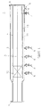
Figure 1 shows an example of a pig receiver configured in use for cleaning a pig. -
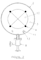
Figure 2 shows a cross-sectional end view through the pig receiver (blind flange not shown for clarity). - As illustrated in
Figure 1 , thereceiver 1 is arranged to enable connection to a pipeline (not shown) and comprises areceiver housing 2 defining aninterior chamber 3 within which, in this example, apig 12 is received and mounted horizontally. Thereceiver housing 2 comprises aseal member 5 for connection to a process pipeline, and aseal member 6 for extraction of the pig. A fluid inlet 7 is coupled to a fluid source (not shown) and extends vertically through the base of thereceiver housing 2 into theinterior chamber 3. A fluidisation andtransportation device 8 is mounted externally to thereceiver housing 2 and is coupled to a downstream processing system (not shown). - The pig receiver illustrated in
Figure 1 further comprises the optional features of afluid outlet 9, which extends from theinterior chamber 3 through the base of thereceiver housing 2 and is coupled to a drainage system (not shown), and aweir plate 10, which is located between the fluid inlet 7 and thefluid outlet 9. - In the example of the present invention illustrated in
Figure 1 , apig 12 travels along a pipeline coupled to thereceiver 1 and enters theinterior chamber 3 of thereceiver housing 2 past the seal member. Thepig retention mechanism 4 is positioned such that, in use, it extends around thepig 12, in order to retain thepig 12 in the middle of theinterior chamber 3. Once thepig 12 is in position, the seal member is sealed, thereby enclosing thepig 12 within theinterior chamber 3, and thereceiver 1 is isolated from the pipeline. - In the example of the present invention illustrated in
Figure 1 , fluid inlet 7 suppliesfluidisation jetting nozzles 13 positioned such that coverage extends along the base of thereceiver housing 2 and such that their position does not hinder operation or removal of the pig. The fluid inlet 7 is operable such that the flow of fluid through the inlet can be controlled by manual or automatic means. Fluid is introduced into theinterior chamber 3 via the fluid inlet 7 to the jetting header pipe and to thejetting nozzles 13 to fluidise the debris within the receiver housing, including debris associate with thepig 12. The fluid may be any suitable fluid (e.g. water) and is preferably pressurized to maximise the removal and fluidisation of debris. - Fluidised debris leaves the
interior chamber 3 via the fluidisation andtransportation device 8. In the example of the present invention illustrated inFigure 1 , excess fluid leaves theinterior chamber 3 via thefluid outlet 9. In this example, aweir plate 10 located between the fluid inlet 7 and thefluid outlet 9 minimises the carryover of excess solid debris, thereby preventing blockage of thefluid outlet 9. If the receiver comprises a plurality of fluid outlets then there may also be a plurality of weir plates and the weir plate(s) may be substituted with a filter or grille arrangement. - The example of the present invention illustrated in
Figure 1 comprises a fluidisingjet header pipe 11 mounted internally within thereceiver housing 2. Thefluidising jets 13 further aid the fluidisation of debris. - In the example of the present invention illustrated in
Figure 1 , a plurality of fluidisation andtransportation devices 8 are mounted externally to thereceiver housing 2 such that they are arranged to receive the fluidised debris from theinterior chamber 3. Saiddevices 8 are positioned such that coverage is along the outer body of thereceiver housing 2, and furthermore are installed such that they do not hinder the operation or removal of the pig. Fluidised debris can exit theinterior chamber 3 via thedevice 8, which is coupled to a downstream processing system (not shown). Thedevice 8 transports the solid and liquid phases of the contaminated waste to for further treatment. - In a preferred embodiment, fluidised debris exits the receiver housing via the fluidisation and transportation device and excess fluid exits via the fluid outlet.
- Suitable fluidisation and transportation devices include Tore® technology devices, which is, for example, disclosed in
WO 96/05 128 - In operation the
seal member 6 will be sealed and theseal member 5 opened to allow the pig to be received in theinterior chamber 3 of the housing. Theseal member 5 is then closed and theoutlet 9, in this example, opened to reduce the pressure in theinterior chamber 3 to a level below that of the pipeline by removal of material from the pipeline which has been carried into thechamber 3 with thepig 12. - Cleaning fluid (in this example water) may then be introduced under pressure via the inlet 7 to surround the
pig 12 and fill thechamber 3. Cleaning can then be carried out and material removed either through the fluidisation andtransportation devices 8, theoutlet 9, or a combination thereof. When cleaning fluid has been removed throughoutlet 9 theweir 10 will retain remaining debris and fluid which can then be removed through the fluidisation andtransportation devices 8. - Once the interior of the pig receiver and, optionally, the pig, have been cleaned the fluid inlet 7 is closed (for example, after a pre-determined length of time) and excess water drains out of the
interior chamber 3 via thedevice 8 and/or thefluid outlet 9. The configuration of thereceiver housing 2 enables the pig to be extracted past theseal member 6. Once removed from the receiver thepig 12 and the interior of the pig receiver can undergo further cleaning, if required. - The present invention enables the removal of the majority of debris from the interior of the pig receiver, and from the
pig 12 itself, whilst thepig 12 is enclosed in the receiver housing. Furthermore, the present invention facilitates the subsequent removal of the fluidised debris from the housing, thereby negating the need for operators to come into contact with the debris. As such, it is advantageous over pig receivers of the prior art because it provides a more efficient, cleaner and safer means of cleaning pigs and pig receivers and processing the waste debris.
Claims (13)
- An apparatus for receiving a pig comprising: a receiver housing arranged to enable connection to a pipeline; a pig retention mechanism mounted within said receiver housing, said pig retention mechanism arranged such that it is operable to retain the pig within the housing; a first sealing member operable to seal the portion of the receiver housing through which the pig can be removed from the apparatus;
a fluid inlet; characterized in that it further comprises a second sealing member operable to seal the portion of the housing that connects aid receiver to the pipeline and
a fluidisation and transportation device arranged to receive the fluidised debris, wherein the apparatus is arranged such that, in use, pressurized fluid is introduced into the enclosed interior of the housing via the fluid inlet in order to fluidise debris which is then removed from the receiver housing via the fluidisation and transportation device. - An apparatus according to claim 1, wherein the fluidisation and transportation device is mounted externally to the receiver housing.
- An apparatus according to claim 1 or 2, further comprising a fluidising jet mounted internally within the receiver housing.
- An apparatus according to any preceding claim, further comprising a fluid outlet arranged to receive excess fluid.
- An apparatus according to claim 4, further comprising a weir plate located between the fluid inlet and the fluid outlet.
- An apparatus according to any preceding claim, wherein the pressurized fluid is water.
- An apparatus according to any preceding claim, arranged such that pressurised fluid can be introduced when the pig is in position within the receiver housing.
- A method for cleaning a pig receiver comprising:sealing a portion of the housing of said receiver which is arranged to enable a pig to be removed from the housing;sealing a portion of the housing of said receiver which is arranged to enable connection to a pipeline;introducing pressurised fluid into the enclosed interior of the receiver housing via a fluid inlet in order to fluidise debris within the receiver housing; andremoving fluidised debris from the receiver housing via a fluidisation and transportation device.
- A method according to claim 8, wherein excess fluid is removed from the receiver housing via a fluid outlet.
- A method according to claim 9, wherein a weir plate located between the fluid inlet and the fluid outlet prevents solid debris from entering the fluid outlet.
- A method according to any of claims 8 to 10, wherein debris is further fluidised by a fluidised jet mounted internally within the receiver housing.
- A method according to any of claims 8 to 11, wherein the pig is in position within the receiver housing when the pressurised fluid is introduced.
- A method according to any of claims 8 to 12, wherein the fluid is water.
Priority Applications (9)
| Application Number | Priority Date | Filing Date | Title |
|---|---|---|---|
| DK10174706.1T DK2422890T3 (en) | 2010-08-31 | 2010-08-31 | Pig receiver |
| EP10174706.1A EP2422890B8 (en) | 2010-08-31 | 2010-08-31 | Pig receiver |
| PL10174706T PL2422890T3 (en) | 2010-08-31 | 2010-08-31 | Pig receiver |
| PCT/EP2011/065011 WO2012028649A1 (en) | 2010-08-31 | 2011-08-31 | Pig receiver |
| CA2806319A CA2806319C (en) | 2010-08-31 | 2011-08-31 | Pig receiver |
| US13/813,607 US8968481B2 (en) | 2010-08-31 | 2011-08-31 | Pig receiver |
| AU2011298396A AU2011298396B2 (en) | 2010-08-31 | 2011-08-31 | Pig receiver |
| MYPI2013000409A MY173581A (en) | 2010-08-31 | 2011-08-31 | Pig receiver |
| RU2013106751/05A RU2543875C2 (en) | 2010-08-31 | 2011-08-31 | Pig receiver |
Applications Claiming Priority (1)
| Application Number | Priority Date | Filing Date | Title |
|---|---|---|---|
| EP10174706.1A EP2422890B8 (en) | 2010-08-31 | 2010-08-31 | Pig receiver |
Publications (3)
| Publication Number | Publication Date |
|---|---|
| EP2422890A1 EP2422890A1 (en) | 2012-02-29 |
| EP2422890B1 true EP2422890B1 (en) | 2013-03-27 |
| EP2422890B8 EP2422890B8 (en) | 2013-05-15 |
Family
ID=43434907
Family Applications (1)
| Application Number | Title | Priority Date | Filing Date |
|---|---|---|---|
| EP10174706.1A Not-in-force EP2422890B8 (en) | 2010-08-31 | 2010-08-31 | Pig receiver |
Country Status (9)
| Country | Link |
|---|---|
| US (1) | US8968481B2 (en) |
| EP (1) | EP2422890B8 (en) |
| AU (1) | AU2011298396B2 (en) |
| CA (1) | CA2806319C (en) |
| DK (1) | DK2422890T3 (en) |
| MY (1) | MY173581A (en) |
| PL (1) | PL2422890T3 (en) |
| RU (1) | RU2543875C2 (en) |
| WO (1) | WO2012028649A1 (en) |
Families Citing this family (26)
| Publication number | Priority date | Publication date | Assignee | Title |
|---|---|---|---|---|
| US9310016B2 (en) | 2010-04-05 | 2016-04-12 | Power Associates International, Inc. | Pig receiver assembly |
| US9593794B2 (en) | 2010-04-05 | 2017-03-14 | Power Associates International, Inc. | Pig receiver assembly |
| EP2679876B1 (en) * | 2012-06-27 | 2016-11-30 | Power Associates International Inc. | Pig receiver assembly |
| SG11201508498QA (en) * | 2013-05-06 | 2015-11-27 | Fmc Separation Systems Bv | Fluidizing unit and discharging system |
| DE102015112658A1 (en) * | 2015-07-31 | 2017-02-02 | Rosen Swiss Ag | Device for feeding and discharging a pig into or out of a pipeline |
| US10024768B1 (en) | 2016-06-17 | 2018-07-17 | Markwest Energy Partners, L.P. | System, method, and apparatus for determining air emissions during pig receiver depressurization |
| US10001240B1 (en) | 2016-11-02 | 2018-06-19 | Markwest Energy Partners, L.P. | Pig ramp, system and method |
| US11607654B2 (en) | 2019-12-30 | 2023-03-21 | Marathon Petroleum Company Lp | Methods and systems for in-line mixing of hydrocarbon liquids |
| CA3103416C (en) | 2019-12-30 | 2022-01-25 | Marathon Petroleum Company Lp | Methods and systems for inline mixing of hydrocarbon liquids |
| CA3104319C (en) | 2019-12-30 | 2023-01-24 | Marathon Petroleum Company Lp | Methods and systems for spillback control of in-line mixing of hydrocarbon liquids |
| US11655940B2 (en) | 2021-03-16 | 2023-05-23 | Marathon Petroleum Company Lp | Systems and methods for transporting fuel and carbon dioxide in a dual fluid vessel |
| US11578638B2 (en) | 2021-03-16 | 2023-02-14 | Marathon Petroleum Company Lp | Scalable greenhouse gas capture systems and methods |
| US12012883B2 (en) | 2021-03-16 | 2024-06-18 | Marathon Petroleum Company Lp | Systems and methods for backhaul transportation of liquefied gas and CO2 using liquefied gas carriers |
| US11578836B2 (en) | 2021-03-16 | 2023-02-14 | Marathon Petroleum Company Lp | Scalable greenhouse gas capture systems and methods |
| US12043905B2 (en) | 2021-08-26 | 2024-07-23 | Marathon Petroleum Company Lp | Electrode watering assemblies and methods for maintaining cathodic monitoring of structures |
| US12180597B2 (en) | 2021-08-26 | 2024-12-31 | Marathon Petroleum Company Lp | Test station assemblies for monitoring cathodic protection of structures and related methods |
| US12129559B2 (en) | 2021-08-26 | 2024-10-29 | Marathon Petroleum Company Lp | Test station assemblies for monitoring cathodic protection of structures and related methods |
| US11447877B1 (en) | 2021-08-26 | 2022-09-20 | Marathon Petroleum Company Lp | Assemblies and methods for monitoring cathodic protection of structures |
| CN114951154A (en) * | 2022-04-27 | 2022-08-30 | 国能联合动力技术(保定)有限公司 | Bolt sleeve inner cavity cleaning system and bolt sleeve pretreatment method |
| US11686070B1 (en) | 2022-05-04 | 2023-06-27 | Marathon Petroleum Company Lp | Systems, methods, and controllers to enhance heavy equipment warning |
| US12012082B1 (en) | 2022-12-30 | 2024-06-18 | Marathon Petroleum Company Lp | Systems and methods for a hydraulic vent interlock |
| US12043361B1 (en) | 2023-02-18 | 2024-07-23 | Marathon Petroleum Company Lp | Exhaust handling systems for marine vessels and related methods |
| US12006014B1 (en) | 2023-02-18 | 2024-06-11 | Marathon Petroleum Company Lp | Exhaust vent hoods for marine vessels and related methods |
| US12455037B2 (en) | 2023-06-21 | 2025-10-28 | Saudi Arabian Oil Company | Scraper receiver with filter upstream of a kicker valve |
| US12297965B2 (en) | 2023-08-09 | 2025-05-13 | Marathon Petroleum Company Lp | Systems and methods for mixing hydrogen with natural gas |
| US12597151B2 (en) | 2023-09-18 | 2026-04-07 | Marathon Petroleum Company Lp | Systems and methods to determine vegetation encroachment along a right-of-way |
Family Cites Families (21)
| Publication number | Priority date | Publication date | Assignee | Title |
|---|---|---|---|---|
| US2481422A (en) * | 1945-06-14 | 1949-09-06 | Dow Chemical Co | Means for spotting a fluid in a well |
| US3146477A (en) * | 1963-04-22 | 1964-09-01 | Panhandle Eastern Pipe Line Co | Combination valve and cleaning ball launcher |
| US3548438A (en) * | 1968-06-26 | 1970-12-22 | North American Rockwell | Automatic oil well dewaxing system |
| US3564634A (en) * | 1968-06-27 | 1971-02-23 | North American Rockwell | Flowline cleaning tool storage and conditioning device |
| SU603440A1 (en) * | 1976-01-08 | 1978-04-25 | Всесоюзный Заочный Институт Пищевой Промышленности | Apparatus for emptying and cleaning the internal space of a pipeline |
| US4750941A (en) * | 1986-01-14 | 1988-06-14 | Horst Gerich | Liquid metering, mixing, dispensing, testing and purging method and apparatus |
| US5051193A (en) * | 1986-03-06 | 1991-09-24 | Aeration Engineering Resources Corporation | Waste water treatment process |
| DE9004899U1 (en) * | 1990-04-30 | 1990-07-05 | Otto Tuchenhagen GmbH & Co KG, 2059 Büchen | Cleanable pigging station |
| US5208936A (en) * | 1991-05-09 | 1993-05-11 | Campbell Douglas C | Variable speed pig for pipelines |
| GB9416244D0 (en) | 1994-08-11 | 1994-10-05 | Merpro Tortek Ltd | Fluidising apparatus |
| US6029302A (en) * | 1995-05-12 | 2000-02-29 | Tuchenhagen Gmbh | Cleanable scraper station |
| GB9614859D0 (en) * | 1996-07-15 | 1996-09-04 | Merpro Tortek Ltd | A method of transporting a solids component of a slurry |
| GB2326209B (en) * | 1997-06-12 | 2002-02-27 | British Gas Plc | Pipeline pigs |
| US6651744B1 (en) * | 1997-11-21 | 2003-11-25 | Superior Services, Llc | Bi-directional thruster pig apparatus and method of utilizing same |
| US8225809B2 (en) * | 2000-07-28 | 2012-07-24 | Hiltap Fittings, Ltd. | Methods and apparatus for introducing a pig into a fluid system |
| US6370721B1 (en) * | 2000-10-03 | 2002-04-16 | Tuboscope I/P, Inc. | Variable speed pig for pipeline applications |
| GB0421769D0 (en) * | 2004-09-30 | 2004-11-03 | Pll Ltd | Pipeline pig |
| GB0603369D0 (en) * | 2006-02-21 | 2006-03-29 | Pipeline Engineering And Suppl | Apparatus for automated launching of multiple pipeline pigs |
| RU2353440C1 (en) * | 2007-08-27 | 2009-04-27 | Общество с ограниченной ответственностью "СИНЕРГИЯ-ЛИДЕР" | Universal chamber for introducing or receiving cleaning elements for pipeline cleaning |
| US20090140133A1 (en) * | 2007-11-29 | 2009-06-04 | Halliburton Energy Services, Inc. | Pipeline pig and method for irradiation of bacteria in a pipeline |
| US7827646B2 (en) * | 2008-02-08 | 2010-11-09 | Tdw Delaware, Inc. | Vortex inhibitor dispersal pig |
-
2010
- 2010-08-31 PL PL10174706T patent/PL2422890T3/en unknown
- 2010-08-31 DK DK10174706.1T patent/DK2422890T3/en active
- 2010-08-31 EP EP10174706.1A patent/EP2422890B8/en not_active Not-in-force
-
2011
- 2011-08-31 RU RU2013106751/05A patent/RU2543875C2/en active
- 2011-08-31 AU AU2011298396A patent/AU2011298396B2/en not_active Ceased
- 2011-08-31 MY MYPI2013000409A patent/MY173581A/en unknown
- 2011-08-31 CA CA2806319A patent/CA2806319C/en not_active Expired - Fee Related
- 2011-08-31 WO PCT/EP2011/065011 patent/WO2012028649A1/en not_active Ceased
- 2011-08-31 US US13/813,607 patent/US8968481B2/en not_active Expired - Fee Related
Also Published As
| Publication number | Publication date |
|---|---|
| PL2422890T3 (en) | 2013-09-30 |
| MY173581A (en) | 2020-02-04 |
| US20130125323A1 (en) | 2013-05-23 |
| DK2422890T3 (en) | 2013-05-13 |
| RU2543875C2 (en) | 2015-03-10 |
| AU2011298396B2 (en) | 2013-11-21 |
| EP2422890A1 (en) | 2012-02-29 |
| RU2013106751A (en) | 2014-10-10 |
| US8968481B2 (en) | 2015-03-03 |
| WO2012028649A1 (en) | 2012-03-08 |
| CA2806319A1 (en) | 2012-03-08 |
| EP2422890B8 (en) | 2013-05-15 |
| CA2806319C (en) | 2014-12-16 |
| AU2011298396A1 (en) | 2013-02-07 |
Similar Documents
| Publication | Publication Date | Title |
|---|---|---|
| CA2806319C (en) | Pig receiver | |
| EP2056975B1 (en) | System and method for cleaning pipes and pipe systems | |
| EP3643414B1 (en) | An ultra-high-pressure water jetting (uhpwj) hydro-blasting cleaning system for surfaces | |
| US9150814B2 (en) | Filter apparatus | |
| US4473529A (en) | Device for collecting purge liquids and gases in an installation containing substances which may possess a certain degree of radioactivity | |
| WO2024061691A1 (en) | System and method for cleaning a waste tank in an aircraft | |
| KR20030079954A (en) | A method and apparatus for radioactive decontamination of a surface situated inside a hollow body | |
| KR101952949B1 (en) | A system for managing and maintaining pipes using a valve for changing flow paths | |
| KR100906681B1 (en) | Pressure Flow Pipeline System | |
| KR20210153937A (en) | Pipe cleaning system and method using the same | |
| CN101952058B (en) | Cleaning and/or unblocking of process equipment | |
| US7438810B2 (en) | Sieve device | |
| EP3170941A1 (en) | System for cleaning a septic tank of a vehicle and a method performing the same | |
| JP5885958B2 (en) | Radiation contaminant removal unit and decontamination method | |
| KR101465781B1 (en) | Pipeline cleaning system | |
| CA2535672C (en) | Settling and evaporation tank apparatus, method and system | |
| RU2179082C2 (en) | Method of and device for cleaning internal surface of pipe-lines | |
| GB2460823A (en) | Water main cleaning arrangement | |
| KR20100130127A (en) | Strain prevention and removal system for scales or foreign substances installed in the cooling unit | |
| WO2025153966A1 (en) | Device and process for the inspection of pressure equipment during operation thereof | |
| JP2583309B2 (en) | Powder channel switching device | |
| GB2473595A (en) | A pipeline cleaning-servicing pig having a through-bore | |
| CZ302150B6 (en) | Device and process for removing sediments from a tank | |
| KR0128463Y1 (en) | Tubing system of sludge treatment unit of the easy removal of residual sludge | |
| CN207792884U (en) | A kind of industrial sewage purification filter device |
Legal Events
| Date | Code | Title | Description |
|---|---|---|---|
| AK | Designated contracting states |
Kind code of ref document: A1 Designated state(s): AL AT BE BG CH CY CZ DE DK EE ES FI FR GB GR HR HU IE IS IT LI LT LU LV MC MK MT NL NO PL PT RO SE SI SK SM TR |
|
| AX | Request for extension of the european patent |
Extension state: BA ME RS |
|
| PUAI | Public reference made under article 153(3) epc to a published international application that has entered the european phase |
Free format text: ORIGINAL CODE: 0009012 |
|
| 17P | Request for examination filed |
Effective date: 20120817 |
|
| GRAP | Despatch of communication of intention to grant a patent |
Free format text: ORIGINAL CODE: EPIDOSNIGR1 |
|
| RIC1 | Information provided on ipc code assigned before grant |
Ipc: F16L 55/46 20060101ALI20120903BHEP Ipc: B08B 9/08 20060101AFI20120903BHEP Ipc: B08B 9/055 20060101ALI20120903BHEP Ipc: B65G 53/30 20060101ALI20120903BHEP |
|
| GRAS | Grant fee paid |
Free format text: ORIGINAL CODE: EPIDOSNIGR3 |
|
| GRAA | (expected) grant |
Free format text: ORIGINAL CODE: 0009210 |
|
| AK | Designated contracting states |
Kind code of ref document: B1 Designated state(s): AL AT BE BG CH CY CZ DE DK EE ES FI FR GB GR HR HU IE IS IT LI LT LU LV MC MK MT NL NO PL PT RO SE SI SK SM TR |
|
| REG | Reference to a national code |
Ref country code: GB Ref legal event code: FG4D |
|
| REG | Reference to a national code |
Ref country code: CH Ref legal event code: EP |
|
| REG | Reference to a national code |
Ref country code: AT Ref legal event code: REF Ref document number: 603032 Country of ref document: AT Kind code of ref document: T Effective date: 20130415 |
|
| RAP2 | Party data changed (patent owner data changed or rights of a patent transferred) |
Owner name: NOV MISSION PRODUCTS UK LTD |
|
| REG | Reference to a national code |
Ref country code: IE Ref legal event code: FG4D |
|
| REG | Reference to a national code |
Ref country code: DK Ref legal event code: T3 |
|
| REG | Reference to a national code |
Ref country code: DE Ref legal event code: R096 Ref document number: 602010005754 Country of ref document: DE Effective date: 20130516 |
|
| REG | Reference to a national code |
Ref country code: NO Ref legal event code: T2 Effective date: 20130327 |
|
| REG | Reference to a national code |
Ref country code: NL Ref legal event code: T3 |
|
| PG25 | Lapsed in a contracting state [announced via postgrant information from national office to epo] |
Ref country code: BG Free format text: LAPSE BECAUSE OF FAILURE TO SUBMIT A TRANSLATION OF THE DESCRIPTION OR TO PAY THE FEE WITHIN THE PRESCRIBED TIME-LIMIT Effective date: 20130627 Ref country code: LT Free format text: LAPSE BECAUSE OF FAILURE TO SUBMIT A TRANSLATION OF THE DESCRIPTION OR TO PAY THE FEE WITHIN THE PRESCRIBED TIME-LIMIT Effective date: 20130327 Ref country code: SE Free format text: LAPSE BECAUSE OF FAILURE TO SUBMIT A TRANSLATION OF THE DESCRIPTION OR TO PAY THE FEE WITHIN THE PRESCRIBED TIME-LIMIT Effective date: 20130327 |
|
| PGFP | Annual fee paid to national office [announced via postgrant information from national office to epo] |
Ref country code: MC Payment date: 20130626 Year of fee payment: 4 |
|
| REG | Reference to a national code |
Ref country code: AT Ref legal event code: MK05 Ref document number: 603032 Country of ref document: AT Kind code of ref document: T Effective date: 20130327 |
|
| REG | Reference to a national code |
Ref country code: LT Ref legal event code: MG4D |
|
| PG25 | Lapsed in a contracting state [announced via postgrant information from national office to epo] |
Ref country code: LV Free format text: LAPSE BECAUSE OF FAILURE TO SUBMIT A TRANSLATION OF THE DESCRIPTION OR TO PAY THE FEE WITHIN THE PRESCRIBED TIME-LIMIT Effective date: 20130327 Ref country code: SI Free format text: LAPSE BECAUSE OF FAILURE TO SUBMIT A TRANSLATION OF THE DESCRIPTION OR TO PAY THE FEE WITHIN THE PRESCRIBED TIME-LIMIT Effective date: 20130327 Ref country code: FI Free format text: LAPSE BECAUSE OF FAILURE TO SUBMIT A TRANSLATION OF THE DESCRIPTION OR TO PAY THE FEE WITHIN THE PRESCRIBED TIME-LIMIT Effective date: 20130327 Ref country code: GR Free format text: LAPSE BECAUSE OF FAILURE TO SUBMIT A TRANSLATION OF THE DESCRIPTION OR TO PAY THE FEE WITHIN THE PRESCRIBED TIME-LIMIT Effective date: 20130628 |
|
| PG25 | Lapsed in a contracting state [announced via postgrant information from national office to epo] |
Ref country code: HR Free format text: LAPSE BECAUSE OF FAILURE TO SUBMIT A TRANSLATION OF THE DESCRIPTION OR TO PAY THE FEE WITHIN THE PRESCRIBED TIME-LIMIT Effective date: 20130327 Ref country code: BE Free format text: LAPSE BECAUSE OF FAILURE TO SUBMIT A TRANSLATION OF THE DESCRIPTION OR TO PAY THE FEE WITHIN THE PRESCRIBED TIME-LIMIT Effective date: 20130327 |
|
| REG | Reference to a national code |
Ref country code: PL Ref legal event code: T3 |
|
| PG25 | Lapsed in a contracting state [announced via postgrant information from national office to epo] |
Ref country code: CZ Free format text: LAPSE BECAUSE OF FAILURE TO SUBMIT A TRANSLATION OF THE DESCRIPTION OR TO PAY THE FEE WITHIN THE PRESCRIBED TIME-LIMIT Effective date: 20130327 Ref country code: RO Free format text: LAPSE BECAUSE OF FAILURE TO SUBMIT A TRANSLATION OF THE DESCRIPTION OR TO PAY THE FEE WITHIN THE PRESCRIBED TIME-LIMIT Effective date: 20130327 Ref country code: PT Free format text: LAPSE BECAUSE OF FAILURE TO SUBMIT A TRANSLATION OF THE DESCRIPTION OR TO PAY THE FEE WITHIN THE PRESCRIBED TIME-LIMIT Effective date: 20130729 Ref country code: ES Free format text: LAPSE BECAUSE OF FAILURE TO SUBMIT A TRANSLATION OF THE DESCRIPTION OR TO PAY THE FEE WITHIN THE PRESCRIBED TIME-LIMIT Effective date: 20130708 Ref country code: AT Free format text: LAPSE BECAUSE OF FAILURE TO SUBMIT A TRANSLATION OF THE DESCRIPTION OR TO PAY THE FEE WITHIN THE PRESCRIBED TIME-LIMIT Effective date: 20130327 Ref country code: SK Free format text: LAPSE BECAUSE OF FAILURE TO SUBMIT A TRANSLATION OF THE DESCRIPTION OR TO PAY THE FEE WITHIN THE PRESCRIBED TIME-LIMIT Effective date: 20130327 Ref country code: EE Free format text: LAPSE BECAUSE OF FAILURE TO SUBMIT A TRANSLATION OF THE DESCRIPTION OR TO PAY THE FEE WITHIN THE PRESCRIBED TIME-LIMIT Effective date: 20130327 Ref country code: IS Free format text: LAPSE BECAUSE OF FAILURE TO SUBMIT A TRANSLATION OF THE DESCRIPTION OR TO PAY THE FEE WITHIN THE PRESCRIBED TIME-LIMIT Effective date: 20130727 |
|
| PGFP | Annual fee paid to national office [announced via postgrant information from national office to epo] |
Ref country code: LU Payment date: 20130902 Year of fee payment: 4 Ref country code: IE Payment date: 20130812 Year of fee payment: 4 |
|
| PG25 | Lapsed in a contracting state [announced via postgrant information from national office to epo] |
Ref country code: CY Free format text: LAPSE BECAUSE OF FAILURE TO SUBMIT A TRANSLATION OF THE DESCRIPTION OR TO PAY THE FEE WITHIN THE PRESCRIBED TIME-LIMIT Effective date: 20130327 |
|
| PLBE | No opposition filed within time limit |
Free format text: ORIGINAL CODE: 0009261 |
|
| STAA | Information on the status of an ep patent application or granted ep patent |
Free format text: STATUS: NO OPPOSITION FILED WITHIN TIME LIMIT |
|
| PG25 | Lapsed in a contracting state [announced via postgrant information from national office to epo] |
Ref country code: IT Free format text: LAPSE BECAUSE OF FAILURE TO SUBMIT A TRANSLATION OF THE DESCRIPTION OR TO PAY THE FEE WITHIN THE PRESCRIBED TIME-LIMIT Effective date: 20130327 |
|
| 26N | No opposition filed |
Effective date: 20140103 |
|
| REG | Reference to a national code |
Ref country code: DE Ref legal event code: R097 Ref document number: 602010005754 Country of ref document: DE Effective date: 20140103 |
|
| PG25 | Lapsed in a contracting state [announced via postgrant information from national office to epo] |
Ref country code: LU Free format text: LAPSE BECAUSE OF NON-PAYMENT OF DUE FEES Effective date: 20140831 Ref country code: MC Free format text: LAPSE BECAUSE OF NON-PAYMENT OF DUE FEES Effective date: 20140901 |
|
| REG | Reference to a national code |
Ref country code: CH Ref legal event code: PL |
|
| PG25 | Lapsed in a contracting state [announced via postgrant information from national office to epo] |
Ref country code: CH Free format text: LAPSE BECAUSE OF NON-PAYMENT OF DUE FEES Effective date: 20140831 Ref country code: LI Free format text: LAPSE BECAUSE OF NON-PAYMENT OF DUE FEES Effective date: 20140831 |
|
| PG25 | Lapsed in a contracting state [announced via postgrant information from national office to epo] |
Ref country code: SM Free format text: LAPSE BECAUSE OF FAILURE TO SUBMIT A TRANSLATION OF THE DESCRIPTION OR TO PAY THE FEE WITHIN THE PRESCRIBED TIME-LIMIT Effective date: 20130327 |
|
| REG | Reference to a national code |
Ref country code: IE Ref legal event code: MM4A |
|
| PG25 | Lapsed in a contracting state [announced via postgrant information from national office to epo] |
Ref country code: TR Free format text: LAPSE BECAUSE OF FAILURE TO SUBMIT A TRANSLATION OF THE DESCRIPTION OR TO PAY THE FEE WITHIN THE PRESCRIBED TIME-LIMIT Effective date: 20130327 |
|
| PGFP | Annual fee paid to national office [announced via postgrant information from national office to epo] |
Ref country code: MT Payment date: 20130828 Year of fee payment: 4 |
|
| PG25 | Lapsed in a contracting state [announced via postgrant information from national office to epo] |
Ref country code: HU Free format text: LAPSE BECAUSE OF FAILURE TO SUBMIT A TRANSLATION OF THE DESCRIPTION OR TO PAY THE FEE WITHIN THE PRESCRIBED TIME-LIMIT; INVALID AB INITIO Effective date: 20100831 Ref country code: MK Free format text: LAPSE BECAUSE OF FAILURE TO SUBMIT A TRANSLATION OF THE DESCRIPTION OR TO PAY THE FEE WITHIN THE PRESCRIBED TIME-LIMIT Effective date: 20130327 |
|
| PG25 | Lapsed in a contracting state [announced via postgrant information from national office to epo] |
Ref country code: IE Free format text: LAPSE BECAUSE OF NON-PAYMENT OF DUE FEES Effective date: 20140831 |
|
| PG25 | Lapsed in a contracting state [announced via postgrant information from national office to epo] |
Ref country code: MT Free format text: LAPSE BECAUSE OF NON-PAYMENT OF DUE FEES Effective date: 20140831 |
|
| REG | Reference to a national code |
Ref country code: FR Ref legal event code: PLFP Year of fee payment: 7 |
|
| REG | Reference to a national code |
Ref country code: FR Ref legal event code: PLFP Year of fee payment: 8 |
|
| REG | Reference to a national code |
Ref country code: FR Ref legal event code: PLFP Year of fee payment: 9 |
|
| PG25 | Lapsed in a contracting state [announced via postgrant information from national office to epo] |
Ref country code: AL Free format text: LAPSE BECAUSE OF FAILURE TO SUBMIT A TRANSLATION OF THE DESCRIPTION OR TO PAY THE FEE WITHIN THE PRESCRIBED TIME-LIMIT Effective date: 20130327 |
|
| PGFP | Annual fee paid to national office [announced via postgrant information from national office to epo] |
Ref country code: PL Payment date: 20190617 Year of fee payment: 10 |
|
| REG | Reference to a national code |
Ref country code: DE Ref legal event code: R081 Ref document number: 602010005754 Country of ref document: DE Owner name: NOV PROCESS & FLOW TECHNOLOGIES UK LTD., STONE, GB Free format text: FORMER OWNER: NOV MISSION PRODUCTS UK LIMITED, MONTROSE, ANGUS, GB |
|
| REG | Reference to a national code |
Ref country code: NL Ref legal event code: PD Owner name: NOV PROCESS & FLOW TECHNOLOGIES UK LIMITED; GB Free format text: DETAILS ASSIGNMENT: CHANGE OF OWNER(S), ASSIGNMENT; FORMER OWNER NAME: NOV MISSION PRODUCTS UK LTD Effective date: 20191203 |
|
| REG | Reference to a national code |
Ref country code: GB Ref legal event code: 732E Free format text: REGISTERED BETWEEN 20191212 AND 20191218 |
|
| REG | Reference to a national code |
Ref country code: NO Ref legal event code: CHAD Owner name: NOV PROCESS & FLOW TECHNOLOGIES UK LIMITED, GB Ref country code: NO Ref legal event code: CREP |
|
| PGFP | Annual fee paid to national office [announced via postgrant information from national office to epo] |
Ref country code: NL Payment date: 20200814 Year of fee payment: 11 |
|
| PGFP | Annual fee paid to national office [announced via postgrant information from national office to epo] |
Ref country code: NO Payment date: 20200811 Year of fee payment: 11 Ref country code: DK Payment date: 20200811 Year of fee payment: 11 Ref country code: DE Payment date: 20200819 Year of fee payment: 11 Ref country code: GB Payment date: 20200819 Year of fee payment: 11 Ref country code: FR Payment date: 20200715 Year of fee payment: 11 |
|
| REG | Reference to a national code |
Ref country code: DE Ref legal event code: R119 Ref document number: 602010005754 Country of ref document: DE |
|
| REG | Reference to a national code |
Ref country code: DK Ref legal event code: EBP Effective date: 20210831 |
|
| REG | Reference to a national code |
Ref country code: NO Ref legal event code: MMEP |
|
| REG | Reference to a national code |
Ref country code: NL Ref legal event code: MM Effective date: 20210901 |
|
| GBPC | Gb: european patent ceased through non-payment of renewal fee |
Effective date: 20210831 |
|
| PG25 | Lapsed in a contracting state [announced via postgrant information from national office to epo] |
Ref country code: NO Free format text: LAPSE BECAUSE OF NON-PAYMENT OF DUE FEES Effective date: 20210831 |
|
| PG25 | Lapsed in a contracting state [announced via postgrant information from national office to epo] |
Ref country code: NL Free format text: LAPSE BECAUSE OF NON-PAYMENT OF DUE FEES Effective date: 20210901 |
|
| PG25 | Lapsed in a contracting state [announced via postgrant information from national office to epo] |
Ref country code: GB Free format text: LAPSE BECAUSE OF NON-PAYMENT OF DUE FEES Effective date: 20210831 Ref country code: FR Free format text: LAPSE BECAUSE OF NON-PAYMENT OF DUE FEES Effective date: 20210831 Ref country code: DK Free format text: LAPSE BECAUSE OF NON-PAYMENT OF DUE FEES Effective date: 20210831 Ref country code: DE Free format text: LAPSE BECAUSE OF NON-PAYMENT OF DUE FEES Effective date: 20220301 |
|
| PG25 | Lapsed in a contracting state [announced via postgrant information from national office to epo] |
Ref country code: PL Free format text: LAPSE BECAUSE OF NON-PAYMENT OF DUE FEES Effective date: 20200831 |