EP2422609A1 - Drive arrangement for corn head equipped with or without a corn stalk chopper - Google Patents
Drive arrangement for corn head equipped with or without a corn stalk chopper Download PDFInfo
- Publication number
- EP2422609A1 EP2422609A1 EP11174998A EP11174998A EP2422609A1 EP 2422609 A1 EP2422609 A1 EP 2422609A1 EP 11174998 A EP11174998 A EP 11174998A EP 11174998 A EP11174998 A EP 11174998A EP 2422609 A1 EP2422609 A1 EP 2422609A1
- Authority
- EP
- European Patent Office
- Prior art keywords
- gear
- stalk
- gear case
- teeth
- torque
- Prior art date
- Legal status (The legal status is an assumption and is not a legal conclusion. Google has not performed a legal analysis and makes no representation as to the accuracy of the status listed.)
- Granted
Links
Images


Classifications
-
- A—HUMAN NECESSITIES
- A01—AGRICULTURE; FORESTRY; ANIMAL HUSBANDRY; HUNTING; TRAPPING; FISHING
- A01D—HARVESTING; MOWING
- A01D34/00—Mowers; Mowing apparatus of harvesters
- A01D34/835—Mowers; Mowing apparatus of harvesters specially adapted for particular purposes
- A01D34/8355—Mowers; Mowing apparatus of harvesters specially adapted for particular purposes for cutting up or crushing remaining standing stalks, e.g. stubble
-
- A—HUMAN NECESSITIES
- A01—AGRICULTURE; FORESTRY; ANIMAL HUSBANDRY; HUNTING; TRAPPING; FISHING
- A01D—HARVESTING; MOWING
- A01D43/00—Mowers combined with apparatus performing additional operations while mowing
- A01D43/08—Mowers combined with apparatus performing additional operations while mowing with means for cutting up the mown crop, e.g. forage harvesters
Definitions
- the present invention relates to drive arrangements for the row units and corn stalk chopper of corn heads, and, more particularly, relates to a drive arrangement for each row unit and associated stalk chopper.
- a known corn stalk residue treating system has been marketed by Deere and Company as the 600C StalkMaster TM .
- This treating system includes stalk rolls located side-by-side beneath the deck plates of the row unit, with each roll including a plurality of longitudinally extending blades spaced angularly about the roll axis, with the blades of the rolls cooperating so as to engage and pull the stalks downward while crimping them along their lengths.
- a flail shredder including two pivotally mounted knives or blades is mounted for cutting the stalks cleanly, once the ears have been removed, so as to leave only a cleanly cut, short stubble rooted to the ground.
- a first gear case is provided for connecting driving power to the gathering chains and stalk rolls carried by each row unit, while a separate second gear case is provided for connecting driving power to the flail shredder.
- the first and second gear cases are respectively protected from overloads caused by the associated driven components coming into contact with rocks and other obstructions by first and second internal radial pin slip clutches located adjacent the gear cases on a power input shaft passing through both gear cases.
- Deere residue treating system works well, it has the draw back that there is insufficient space available along the drive input shaft for slip clutches of adequate capacity to be used if the corn head is set up for harvesting narrow row corn. Also, the present Deere residue treating system is not easily switched between chopping and non-chopping modes.
- An object of the invention is to provide a relatively compact drive arrangement for either driving the stalk rolls, gathering chains and chopper of each row unit of a corn head, or for driving two row units in the absence of a chopper, with the drive arrangement including a single slip clutch for protecting the drive elements of the drive arrangement.
- the present invention relates to corn heads for agricultural combines and more specifically relates to drive arrangements for such corn heads as may, or may not be, equipped with choppers.
- a slip clutch having a central hub mounted for rotation with a main power shaft and having an outer cylindrical shell coupled to the hub by a spring-engaged slip surface arrangement, the shell having opposite ends respectively secured to first and second output couplers respectively coupled to first and second tubular input drive shafts mounted for rotation about the main power shaft and respectively providing drive inputs either to a row unit drive case and an associated chopper blade drive case, when a chopper blade is associated with each drive unit, or to the row unit drive cases of adjacent row units in the absence of the corn head being equipped with chopper blades.
- a corn head 10 including a transversely extending frame (not shown) across the width of which is attached eight identical, forwardly projecting row units of which a major portion of one is shown at 12.
- the row units 12 are disposed in side-by-side relationship to each other and are spaced apart a distance commensurate with that of the spacing between adjacent rows of corn to be harvested.
- the row units 12 each include a support frame (not shown), with it being noted that it is conventional to mount the frames of the row units 12 for transverse adjustment in order to accommodate corn rows spaced apart by different distances.
- Extending over and mounted to adjacent portions of the row unit frames are seven identical central crop dividers 14, with a right crop divider 16 being located over a right hand portion of the right row unit frame, and with a left crop divider 18 being located over a left hand portion of the left row unit frame.
- the crop dividers 14, 16 and 18 each serve to separate comingled corn stalks of adjacent corn rows from one another, with the crop dividers defining longitudinal passages 20 between them which are spaced from each other a distance equal to that of the corn rows to be harvested.
- each row unit includes an enclosed row unit gear case 22 including a housing 23 containing a row unit gear train 24 arranged for effecting counter rotation of parallel, right and left, upwardly projecting gathering chain drive shafts 26 and 28, respectively, supported by the gear case 22.
- the row unit gear train 24 is also arranged for effecting counter rotation of parallel right and left, stalk roll drive shafts 30 and 32, respectively, supported in, and projecting forwardly from, a central forward wall of the gear case 22.
- the gear train 24 includes a tubular input shaft 34 containing, and being mounted for rotation about, a main power shaft 36 projecting through a rear location of the row unit housing 23.
- a spur gear 38 is mounted on the input shaft 34 within the gear case 22 and is meshed with a transfer spur gear 40 carried by an intermediate shaft 42 also mounted for rotation in the gear case 22.
- the spur gear 40 is meshed with a spur gear 44 carried by a shaft 46 mounted for rotation in the gear case 22.
- Respectively mounted to right and left ends of the shaft 46 are right and left bevel gears 48 and 50 which are respectively meshed with bevel gears 52 and 54 carried at the lower ends of the right and left gathering chain drive shafts 26 and 28.
- Respectively mounted on the shaft 46 to the right and to the left of the spur gear 44 are right and left bevel gears 56 and 58 that are meshed with bevel gears 60 and 62 mounted on the rear ends of the stalk roll drive shafts 30 and 32.
- a separate chopping gear case 64 is associated with the row unit gear case 22 and contains a gear train 66 arranged for driving an upright chopper blade drive shaft 68 carrying a flail type chopper blade arrangement 70 at its lower end.
- the gear train 66 includes a tubular input shaft 72 mounted for rotation about the main power shaft 36 in a region extending through a rear portion of the chopper blade gear case 64.
- a bevel gear 74 Mounted on the input shaft 72 within the rear portion of the gear case 64 is a bevel gear 74 that is meshed with a bevel gear 75 carried at the rear end of a fore-and aft extending intermediate shaft 76 that has a bevel gear 78 mounted to its forward end and meshed with a bevel gear 80 mounted to a top end of the chopper blade drive shaft 68.
- the chopper blade arrangement 70 comprises a hub provided with diametrically opposite, radially outwardly projecting blade mounts 82 and 84 to which flail-type chopping blades 86 and 88 are respectively mounted for pivoting about inner end locations, the blades 86 and 88 being disposed for cleanly cutting corn stalks located in a row centered between the stalk roll drive shafts 30 and 32 so as to leave a relatively short stalk stubble rooted to the ground.
- a dual output slip clutch 90 Located on the main power shaft 36 at a location between the row unit gear case 22 and the chopping blade gear case 64 is a dual output slip clutch 90, which may be of any of a variety of designs capable of delivering a limited torque to respective output couplers at opposite ends of the slip clutch.
- the slip clutch 90 as depicted schematically in Fig. 5 , comprises a central hub 92 surrounded by a cylindrical shell 96 having right and left mounting flanges 98 and 100, respectively, at its opposite ends coupled, as by bolts 102, to mounting flanges 104 and 106 of cylindrical, right and left output couplers 108 and 110, respectively.
- the hub 92 is provided with a longitudinal bore (not shown) dimensioned complementary to, and receiving the main power shaft 36, which is hexagonal in cross section, the hub 92 thus being mounted for rotating in concert with the main power shaft 36.
- the hub 92 includes an enlarged right end section 112 provided with an annular set of teeth 114 projecting axially toward the right.
- a torque transfer ring 116 Encircling the main power shaft 36 at a location rightward of the hub 92 is a torque transfer ring 116 provided with an annular set of teeth118 shaped complementary to and, projecting axially to the left into engagement with the set of teeth 114 of the hub 92.
- the torque transfer ring 116 is coupled directly to the right output coupler 110 by a plurality of axially extending pins 120 received in blind bores 122 arranged in a circular pattern in the left side of the right output coupler 108 and in through bores 124 provided in the torque transfer ring 116 in alignment with the blind bores 122, noting that only two of each of the blind bores, through bores and pins are shown for the sake of clarity.
- the amount of torque which can be transferred through the engaged sets of teeth 114 and 118 is determined by the shape of the teeth and by a biasing force produced by a coil compression spring 126 received about the main power shaft 36 and compressed between the enlarged end section 112 of the hub 92 and a spacer ring 128 received within the shell 96 and having a left surface engaged with a right surface of the left output coupler 110.
- the sets of engaged teeth 114 and 118, the spring 126 and the shell 96 cooperate to define a torque-limited connection between the slip clutch hub 92 and the slip clutch output couplers 108 and 110.
- a left end region of the tubular input shaft 34 is provided with an exterior spline arrangement that is complementary to, and engaged with, an interior spline arrangement of the left output coupler 110 so as to define a spline connection 130.
- an end region of the tubular input shaft 72 is provided with an exterior spline arrangement that is complementary to, and engaged with, an interior spline arrangement of the right output coupler 108 so as to define a spline connection 132.
- the chopper gear case 64 may be omitted, with a tubular input shaft 132 replacing the input shaft 72 and extending from the right output coupler 108 of the slip clutch 90 into the row unit gear case 22 of an adjacent row unit 12, with the spur gear 38 of that row unit gear case being mounted on the input shaft 132.
- the slip clutch 90 then serves to protect the adjacent row units 12 from overloads.
- the slip clutch 140 used with a second embodiment of the invention.
- the slip clutch 140 includes a central cylindrical hub 142 mounted for rotation with the main power shaft 36, the hub 142 being joined to cylindrical tubular, right and left spring mounts 144 and 146, respectively, having spring retainer rings 148 and 150 screwed onto outer ends thereof.
- the hub 142 has right and left annular sets of axially facing teeth 152 and 154 respectively engaged with recesses between complementary, axially projecting sets of teeth 156 and 158 respectively provided at inner faces of right and left torque transfer rings 160 and 162.
- the torque transfer rings 160 and 162 are mounted for sliding along the spring mounts 144 and 146, and are respectively provided with right and left sets of angularly spaced, radial tabs 164 and 166.
- Mounted so as to respectively encircle the spring mounts 144 and 146 are right and left cylindrical shell members 168 and 170, the left end of the right shell member 168 being provided with a set of axially extending slots 172 respectively receiving the set of tabs 164 of the right torque transfer ring 160, and the right end of the left shell member 170 being provided with a set of slots 174 respectively receiving the set of tabs 166 of the right torque transfer ring 162.
- the shell members 168 and 170 are respectively provided with annular mounting flanges 176 and 178 at their right and left ends, with right and left output couplers 180 and 182 including annular flanges 184 and 186, respectively, mounted to the flanges 176 and 178 by bolt fasteners 188.
- a coil compression spring 190 is received on the spring mount 144 and is compressed between the retainer ring 148 and the right torque transfer ring 160 so as to keep the set of teeth 156 in yieldable biased engagement with the set of teeth 152.
- a coil compression spring 192 is received on the spring mount 146 and is compressed between the retainer ring 150 and the left torque transfer ring 162 so as to keep the set of teeth 156 in yieldable biased engagement with the set of teeth 154.
- the output couplers 180 and 182 are separately coupled to the central hub 142 by separate torque-limited connections respectively defined by the sets of teeth 152 and 158, the tabs 164 and shell 168 together with the spring 190, and the sets of teeth 154 and 156, the tabs 166 and shell 170, together with the spring 192.
- Stacks of Belleville washers could be substituted for the springs 190 and 192, if desired.
- slip clutch 140 Installation of the slip clutch 140 on the corn head 10, when equipped for chopping, as shown in Figs. 2 and 3 , is accomplished by mounting the hub 142 for rotation with the main power shaft 36 at a location between the row unit gear case 22 and the chopper gear case 64.
- the output couplers 180 and 182 of the slip clutch 140 will respectively be coupled for transmitting torque to the input shaft 34 of the row unit gear case, and to the input shaft 72 of the chopper gear case 64.
- the slip clutch 140 operates in a similar manner to protect the drive trains of adjacent row units 12 when the slip clutch 140 is used to deliver drive torque to the drive trains 24 of adjacent row unit gear cases 22 when an associated chopping gear case 64 is either not present or not being currently used for chopping corn stalks.
Landscapes
- Life Sciences & Earth Sciences (AREA)
- Environmental Sciences (AREA)
- Gear Transmission (AREA)
- Mechanical Operated Clutches (AREA)
Abstract
Description
- The present invention relates to drive arrangements for the row units and corn stalk chopper of corn heads, and, more particularly, relates to a drive arrangement for each row unit and associated stalk chopper.
- The current practice of no-till farming results in considerable plant residue being left on the field after a previous crop is harvested. This residue is especially thick when the previous crop is corn and managing this corn residue has become a big challenge. In order to promote residue deterioration, various ways of breaking down the residual corn stalks have been developed including placing chopping knife rollers and/or shredder rollers or rotary flail shredders beneath the row unit deck plates.
- A known corn stalk residue treating system has been marketed by Deere and Company as the 600C StalkMaster™. This treating system includes stalk rolls located side-by-side beneath the deck plates of the row unit, with each roll including a plurality of longitudinally extending blades spaced angularly about the roll axis, with the blades of the rolls cooperating so as to engage and pull the stalks downward while crimping them along their lengths. A flail shredder including two pivotally mounted knives or blades is mounted for cutting the stalks cleanly, once the ears have been removed, so as to leave only a cleanly cut, short stubble rooted to the ground. A first gear case is provided for connecting driving power to the gathering chains and stalk rolls carried by each row unit, while a separate second gear case is provided for connecting driving power to the flail shredder. The first and second gear cases are respectively protected from overloads caused by the associated driven components coming into contact with rocks and other obstructions by first and second internal radial pin slip clutches located adjacent the gear cases on a power input shaft passing through both gear cases.
- While the above-noted Deere residue treating system works well, it has the draw back that there is insufficient space available along the drive input shaft for slip clutches of adequate capacity to be used if the corn head is set up for harvesting narrow row corn. Also, the present Deere residue treating system is not easily switched between chopping and non-chopping modes.
- An object of the invention is to provide a relatively compact drive arrangement for either driving the stalk rolls, gathering chains and chopper of each row unit of a corn head, or for driving two row units in the absence of a chopper, with the drive arrangement including a single slip clutch for protecting the drive elements of the drive arrangement.
- The present invention relates to corn heads for agricultural combines and more specifically relates to drive arrangements for such corn heads as may, or may not be, equipped with choppers.
- The foregoing object is accomplished, in a first embodiment, by providing a slip clutch having a central hub mounted for rotation with a main power shaft and having an outer cylindrical shell coupled to the hub by a spring-engaged slip surface arrangement, the shell having opposite ends respectively secured to first and second output couplers respectively coupled to first and second tubular input drive shafts mounted for rotation about the main power shaft and respectively providing drive inputs either to a row unit drive case and an associated chopper blade drive case, when a chopper blade is associated with each drive unit, or to the row unit drive cases of adjacent row units in the absence of the corn head being equipped with chopper blades.
- The foregoing and other objects of the invention will be apparent from a reading of the ensuing description together with the appended drawings.
-
-
Fig. 1 is a schematic front view of a corn head for an agricultural combine including row units with which the present invention is particularly adapted for use. -
Fig 2 is a right top perspective view showing a row unit gear case and an associated stalk chopper gear case, with a slip clutch being located between the row unit gear case on a main power shaft and having first and second output couplers respectively coupled to first and second tubular input shafts received over the power shaft and extending into the row unit and chopper gear cases. -
Fig. 3 is a schematic top view illustrating the gear trains contained within the row unit gear case and the associated chopper blade gear case illustrated inFig. 2 . -
Fig. 4 is a schematic top view illustrating the gear trains contained within a pair of adjacent row unit gear cases and including respective input shafts coupled to the first and second output couplers of the slip clutch in the absence of associated chopping gear cases. -
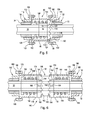
Fig. 5 is a partial longitudinal sectional view of the slip clutch illustrated inFigs. 2-4 including a shell having opposite ends respectively connected for driving first and second output couplers. -
Fig. 6 is a partial longitudinal sectional view of another slip clutch, which can be used in lieu of that shown inFig. 5 , having first and second couplers at its opposite ends which are individually driven. - Referring now to
Fig. 1 , there is shown acorn head 10 including a transversely extending frame (not shown) across the width of which is attached eight identical, forwardly projecting row units of which a major portion of one is shown at 12. Therow units 12 are disposed in side-by-side relationship to each other and are spaced apart a distance commensurate with that of the spacing between adjacent rows of corn to be harvested. Therow units 12 each include a support frame (not shown), with it being noted that it is conventional to mount the frames of therow units 12 for transverse adjustment in order to accommodate corn rows spaced apart by different distances. Extending over and mounted to adjacent portions of the row unit frames are seven identicalcentral crop dividers 14, with aright crop divider 16 being located over a right hand portion of the right row unit frame, and with aleft crop divider 18 being located over a left hand portion of the left row unit frame. Thecrop dividers longitudinal passages 20 between them which are spaced from each other a distance equal to that of the corn rows to be harvested. - Referring now also to
Figs. 2 and3 , it can be seen that each row unit includes an enclosed rowunit gear case 22 including ahousing 23 containing a rowunit gear train 24 arranged for effecting counter rotation of parallel, right and left, upwardly projecting gatheringchain drive shafts gear case 22. The rowunit gear train 24 is also arranged for effecting counter rotation of parallel right and left, stalkroll drive shafts gear case 22. - The
gear train 24 includes atubular input shaft 34 containing, and being mounted for rotation about, amain power shaft 36 projecting through a rear location of therow unit housing 23. Aspur gear 38 is mounted on theinput shaft 34 within thegear case 22 and is meshed with atransfer spur gear 40 carried by anintermediate shaft 42 also mounted for rotation in thegear case 22. Thespur gear 40 is meshed with aspur gear 44 carried by ashaft 46 mounted for rotation in thegear case 22. Respectively mounted to right and left ends of theshaft 46 are right andleft bevel gears bevel gears chain drive shafts shaft 46 to the right and to the left of thespur gear 44 are right andleft bevel gears bevel gears roll drive shafts - It can also be seen in
Figs. 2 and3 , that a separatechopping gear case 64 is associated with the rowunit gear case 22 and contains agear train 66 arranged for driving an upright chopperblade drive shaft 68 carrying a flail typechopper blade arrangement 70 at its lower end. Specifically, thegear train 66 includes atubular input shaft 72 mounted for rotation about themain power shaft 36 in a region extending through a rear portion of the chopperblade gear case 64. Mounted on theinput shaft 72 within the rear portion of thegear case 64 is abevel gear 74 that is meshed with abevel gear 75 carried at the rear end of a fore-and aft extendingintermediate shaft 76 that has abevel gear 78 mounted to its forward end and meshed with a bevel gear 80 mounted to a top end of the chopperblade drive shaft 68. Thechopper blade arrangement 70 comprises a hub provided with diametrically opposite, radially outwardly projectingblade mounts type chopping blades blades roll drive shafts - Located on the
main power shaft 36 at a location between the rowunit gear case 22 and the choppingblade gear case 64 is a dualoutput slip clutch 90, which may be of any of a variety of designs capable of delivering a limited torque to respective output couplers at opposite ends of the slip clutch. - The
slip clutch 90, as depicted schematically inFig. 5 , comprises acentral hub 92 surrounded by acylindrical shell 96 having right andleft mounting flanges bolts 102, to mountingflanges left output couplers hub 92 is provided with a longitudinal bore (not shown) dimensioned complementary to, and receiving themain power shaft 36, which is hexagonal in cross section, thehub 92 thus being mounted for rotating in concert with themain power shaft 36. Thehub 92 includes an enlargedright end section 112 provided with an annular set ofteeth 114 projecting axially toward the right. Encircling themain power shaft 36 at a location rightward of thehub 92 is atorque transfer ring 116 provided with an annular set of teeth118 shaped complementary to and, projecting axially to the left into engagement with the set ofteeth 114 of thehub 92. Thetorque transfer ring 116 is coupled directly to theright output coupler 110 by a plurality of axially extendingpins 120 received inblind bores 122 arranged in a circular pattern in the left side of theright output coupler 108 and in throughbores 124 provided in thetorque transfer ring 116 in alignment with theblind bores 122, noting that only two of each of the blind bores, through bores and pins are shown for the sake of clarity. The amount of torque which can be transferred through the engaged sets ofteeth coil compression spring 126 received about themain power shaft 36 and compressed between the enlargedend section 112 of thehub 92 and aspacer ring 128 received within theshell 96 and having a left surface engaged with a right surface of theleft output coupler 110. - Thus, it will be appreciated that the sets of engaged
teeth spring 126 and theshell 96 cooperate to define a torque-limited connection between theslip clutch hub 92 and the slipclutch output couplers - As can be seen in
Figs 5 and 6 , a left end region of thetubular input shaft 34 is provided with an exterior spline arrangement that is complementary to, and engaged with, an interior spline arrangement of theleft output coupler 110 so as to define aspline connection 130. Similarly, an end region of thetubular input shaft 72 is provided with an exterior spline arrangement that is complementary to, and engaged with, an interior spline arrangement of theright output coupler 108 so as to define aspline connection 132. - Thus, under normal operating conditions, torque supplied by the
main power shaft 36 will be transferred through theslip clutch 90 to the rowunit gear case 22 and thechopping gear case 64 by way of theoutput couplers input shafts gear cases slip clutch 90 will slip with the sets ofteeth corn head 10 is disconnected or the condition causing the overload is abated. - Referring now to
Fig. 4 , it can be seen that when no chopping is desired, thechopper gear case 64 may be omitted, with atubular input shaft 132 replacing theinput shaft 72 and extending from theright output coupler 108 of theslip clutch 90 into the rowunit gear case 22 of anadjacent row unit 12, with thespur gear 38 of that row unit gear case being mounted on theinput shaft 132. As an alternative to removing thechopper gear case 64, it is possible to remove only theinput shaft 72 andbevel gear 74, with theinput shaft 132 extending through thechopping gear case 64. It any event, it will be appreciated that theslip clutch 90 then serves to protect theadjacent row units 12 from overloads. - Referring now to
Fig. 6 , there is shown aslip clutch 140 used with a second embodiment of the invention. Like theslip clutch 90 described above, theslip clutch 140 includes a centralcylindrical hub 142 mounted for rotation with themain power shaft 36, thehub 142 being joined to cylindrical tubular, right andleft spring mounts spring retainer rings hub 142 has right and left annular sets of axially facingteeth teeth torque transfer rings torque transfer rings spring mounts radial tabs spring mounts cylindrical shell members right shell member 168 being provided with a set of axially extendingslots 172 respectively receiving the set oftabs 164 of the righttorque transfer ring 160, and the right end of theleft shell member 170 being provided with a set ofslots 174 respectively receiving the set oftabs 166 of the righttorque transfer ring 162. Theshell members annular mounting flanges left output couplers annular flanges flanges bolt fasteners 188. Acoil compression spring 190 is received on thespring mount 144 and is compressed between theretainer ring 148 and the righttorque transfer ring 160 so as to keep the set ofteeth 156 in yieldable biased engagement with the set ofteeth 152. Similarly, acoil compression spring 192 is received on thespring mount 146 and is compressed between theretainer ring 150 and the lefttorque transfer ring 162 so as to keep the set ofteeth 156 in yieldable biased engagement with the set ofteeth 154. - Thus, the
output couplers central hub 142 by separate torque-limited connections respectively defined by the sets ofteeth tabs 164 andshell 168 together with thespring 190, and the sets ofteeth tabs 166 andshell 170, together with thespring 192. Stacks of Belleville washers could be substituted for thesprings - Installation of the
slip clutch 140 on thecorn head 10, when equipped for chopping, as shown inFigs. 2 and3 , is accomplished by mounting thehub 142 for rotation with themain power shaft 36 at a location between the rowunit gear case 22 and thechopper gear case 64. Theoutput couplers slip clutch 140 will respectively be coupled for transmitting torque to theinput shaft 34 of the row unit gear case, and to theinput shaft 72 of thechopper gear case 64. - Operation of the corn head with the
slip clutch 140 used in lieu of theslip clutch 90, will result in each of thegear cases gear train 24 of the rowunit gear case 22 should experience an overload, thedrive teeth 156 of the lefttorque transfer ring 162 will slip relative to the left set ofdrive teeth 154 of thehub 142 causing the lefttorque transfer ring 162 to shift leftward against the resistance of thespring 192 with the set oftabs 166 moving axially within theslots 174, while the set ofteeth 158 of the righttorque transfer ring 160 will remain engaged with the set ofteeth 152 of thehub 142 so that drive torque is still supplied to thechopper gear case 64. Slippage between the sets ofteeth main power shaft 36 is disconnected or the overload is abated. Similarly, if thegear train 66 of thechopping gear case 64 should experience an overload, slippage will take place between the set ofteeth 158 of the righttorque transfer ring 160 the right set ofteeth 152 of thehub 142, while the left set ofteeth 154 of thehub 142 will remain in driving engagement with the set ofteeth 156 of the lefttorque transfer ring 162. Of course, if the gear trains of both of thegear cases hub 142 and the sets of teeth of the right and left torque transfer rings 160 and 162, with the transfer of drive torque being interrupted to both the row unit gear train and the chopper unit gear train. - The
slip clutch 140 operates in a similar manner to protect the drive trains ofadjacent row units 12 when theslip clutch 140 is used to deliver drive torque to the drive trains 24 of adjacent rowunit gear cases 22 when an associatedchopping gear case 64 is either not present or not being currently used for chopping corn stalks.
Claims (5)
- A corn head (10), comprising:a plurality of row units (12) mounted in side-by-side spaced relationship across said corn head (10);each row unit (12) including a plurality of driven stalk-engaging elements supported on a respective stalk-engaging element drive shaft;a first gear case (22) supporting a first set of drive shafts for respectively driving at least some of said stalk-engaging elements of one of said row units (12) and containing a gear train including an input gear coupled for driving respective output gears coupled to said first set of drive shafts;characterized by a second gear case (64) supporting one of either a further drive shaft supporting a respective further stalk-engaging element of said one of said row units (12), or with a respective second set of drive shafts for driving at least some of said stalk-engaging elements of another of said row units (12) positioned adjacent said one of said row units (12), the second gear case (64) containing a second gear train including a second input gear coupled for driving one of either said further drive shaft, or for driving a respective second set of output gears respectively associated with said second set of drive shafts;a main power supply shaft (36) extending through said first and second gear cases (22, 64); anda dual direction slip clutch (140) having a hub mounted on said main power supply shaft (36) between said first and second gear cases (22,64), and first and second output couplers having a torque-limited connection with said hub and being coupled to said input gears of said first and second gear boxes (22,64).
- The corn head (10), as defined in claim 1, wherein said plurality of driven stalk-engaging elements includes a stalk-chopping blade arrangement; and said second gear case supporting a stalk-chopping drive shaft, with said second output coupler of said slip clutch being coupled to an input gear located in said second gear case and coupled for transferring power to said stalk-chopping drive shaft..
- The corn head (10), as defined in claim 1, wherein said second gear case is identical to, and on an opposite side of said slip clutch from said first gear case.
- The corn head (10), as defined in claim 2, wherein said first and second output couplers are respectively coupled, on the one hand, to said hub by first and second torque-limited connections, and on the other hand, to said first and second input gears of said first and second gear boxes, whereby said torque limited connections can slip in unison or independently depending upon a given torque load respectively imposed on said first and second torque-limited connections.
- The corn head (10), as defined in claim 4, wherein said hub of said slip clutch has first and second sets of axially outwardly facing teeth at opposite ends thereof; a first torque transfer member being connected to said first output coupler and including a third set of teeth engaged with said first set of teeth, and a second torque transfer member being connected to said second output coupler and including a fourth set of teeth engaged with said second sect of teeth; and first and second springs acting between said hub and said first and second torque transfer members so as to effect limited-torque connections respectively between the first and third sets of teeth and the second and fourth sets of teeth.
Applications Claiming Priority (1)
| Application Number | Priority Date | Filing Date | Title |
|---|---|---|---|
| US12/870,243 US7937918B1 (en) | 2010-08-27 | 2010-08-27 | Drive arrangement for corn head equipped with or without a corn stalk chopper |
Publications (2)
| Publication Number | Publication Date |
|---|---|
| EP2422609A1 true EP2422609A1 (en) | 2012-02-29 |
| EP2422609B1 EP2422609B1 (en) | 2013-03-06 |
Family
ID=43928188
Family Applications (1)
| Application Number | Title | Priority Date | Filing Date |
|---|---|---|---|
| EP11174998A Active EP2422609B1 (en) | 2010-08-27 | 2011-07-22 | Drive arrangement for corn head equipped with or without a corn stalk chopper |
Country Status (3)
| Country | Link |
|---|---|
| US (1) | US7937918B1 (en) |
| EP (1) | EP2422609B1 (en) |
| BR (1) | BRPI1104220B1 (en) |
Families Citing this family (17)
| Publication number | Priority date | Publication date | Assignee | Title |
|---|---|---|---|---|
| FR3009775B1 (en) * | 2013-08-23 | 2015-08-07 | Kuhn Sa | HARVESTING MACHINE COMPRISING AN IMPROVED LUBRICATION DEVICE |
| US9578804B2 (en) | 2014-04-23 | 2017-02-28 | Cnh Industrial America Llc | Header for an agricultural harvester with independent sub-system drives |
| DE102014113008A1 (en) * | 2014-09-10 | 2016-03-10 | Claas Selbstfahrende Erntemaschinen Gmbh | Method for operating a combine harvester |
| US9913430B2 (en) * | 2014-09-15 | 2018-03-13 | Cnh Industrial America Llc | Power takeoff drive assembly for a corn header of an agricultural harvester |
| KR102102064B1 (en) * | 2015-09-18 | 2020-04-17 | 얀마 가부시키가이샤 | combine |
| DE102015116372A1 (en) * | 2015-09-28 | 2017-03-30 | Carl Geringhoff Gmbh & Co. Kg | Device for harvesting stalky stalks |
| US10582661B2 (en) * | 2015-12-18 | 2020-03-10 | Kopper Kutter, LLC | System and method for converting cutting and gathering system of a corn head |
| DE102017207337A1 (en) * | 2016-07-20 | 2018-01-25 | Deere & Company | Mulching device for processing plant stumps standing on a field |
| US10820509B2 (en) | 2017-08-08 | 2020-11-03 | Cnh Industrial America Llc | Foldable corn head |
| EP3556197B1 (en) * | 2018-04-17 | 2021-03-24 | CNH Industrial Belgium NV | Header with multiple row elements |
| US10694671B2 (en) * | 2018-04-19 | 2020-06-30 | Cnh Industrial America Llc | Header with multiple row elements |
| US11096328B2 (en) | 2018-12-27 | 2021-08-24 | Cnh Industrial America Llc | Agricultural header with damage-reducing clutch |
| US11452252B2 (en) | 2020-01-16 | 2022-09-27 | Cnh Industrial America Llc | Torque damper for agricultural harvester header |
| CN111637216A (en) * | 2020-04-30 | 2020-09-08 | 勇猛机械股份有限公司 | Independent single light-duty ear picking gear box suitable for small row spacing |
| US11746836B2 (en) | 2021-08-24 | 2023-09-05 | Cnh Industrial America Llc | Lubrication mechanism of clutch for agricultural harvester |
| US11825770B1 (en) | 2022-06-29 | 2023-11-28 | Cnh Industrial America Llc | Agricultural vehicle with debris-purging clutch assembly |
| US12565914B2 (en) * | 2022-12-09 | 2026-03-03 | Cnh Industrial America Llc | Power transfer arrangement including coupling clutches for an agricultural vehicle |
Citations (3)
| Publication number | Priority date | Publication date | Assignee | Title |
|---|---|---|---|---|
| US3858384A (en) * | 1972-03-20 | 1975-01-07 | White Motor Canada | Corn header with automatic adjustment of stalk rolls |
| US20040079061A1 (en) * | 1999-10-27 | 2004-04-29 | Richard Wubbels | Dual slip clutch arrangement |
| US20090192734A1 (en) * | 2008-01-29 | 2009-07-30 | Mackin Ryan P | Corn head clutch monitor |
Family Cites Families (8)
| Publication number | Priority date | Publication date | Assignee | Title |
|---|---|---|---|---|
| US1883402A (en) * | 1927-08-08 | 1932-10-18 | Ronning Adolph | Harvesting machine |
| US3462928A (en) | 1967-04-18 | 1969-08-26 | Deere & Co | Harvester roll structure and support therefor |
| US3488980A (en) * | 1968-05-29 | 1970-01-13 | Deere & Co | Torque limiting clutch |
| US3643767A (en) * | 1970-11-27 | 1972-02-22 | Gehl Co | Clutch mechanism having power disengagement |
| US3797621A (en) * | 1972-11-17 | 1974-03-19 | Scott & Fetzer Co | Slip clutch |
| US3982385A (en) * | 1975-07-03 | 1976-09-28 | Sperry Rand Corporation | Stalk rolls for corn harvesters |
| US4227366A (en) | 1979-08-06 | 1980-10-14 | Sperry Corporation | Corn header drive system |
| US4244162A (en) * | 1979-08-06 | 1981-01-13 | Sperry Corporation | Row unit frame |
-
2010
- 2010-08-27 US US12/870,243 patent/US7937918B1/en active Active
-
2011
- 2011-07-22 EP EP11174998A patent/EP2422609B1/en active Active
- 2011-08-25 BR BRPI1104220-6A patent/BRPI1104220B1/en active IP Right Grant
Patent Citations (3)
| Publication number | Priority date | Publication date | Assignee | Title |
|---|---|---|---|---|
| US3858384A (en) * | 1972-03-20 | 1975-01-07 | White Motor Canada | Corn header with automatic adjustment of stalk rolls |
| US20040079061A1 (en) * | 1999-10-27 | 2004-04-29 | Richard Wubbels | Dual slip clutch arrangement |
| US20090192734A1 (en) * | 2008-01-29 | 2009-07-30 | Mackin Ryan P | Corn head clutch monitor |
Also Published As
| Publication number | Publication date |
|---|---|
| EP2422609B1 (en) | 2013-03-06 |
| US7937918B1 (en) | 2011-05-10 |
| BRPI1104220A2 (en) | 2013-01-22 |
| BRPI1104220B1 (en) | 2018-04-17 |
Similar Documents
| Publication | Publication Date | Title |
|---|---|---|
| EP2422609B1 (en) | Drive arrangement for corn head equipped with or without a corn stalk chopper | |
| CN105432227B (en) | Power take-off drive assembly for a corn header of an agricultural harvester | |
| EP2734029B1 (en) | Modular agricultural cutting unit for a working machine | |
| CN109379981B (en) | Foldable corn cutting head | |
| CA1126964A (en) | Corn header drive system | |
| RU2638187C2 (en) | Hinged unit for corn harvesting | |
| US9386747B2 (en) | Stalk roll integrated crop scraper | |
| US12453311B2 (en) | Electric row unit drive system for corn header of combine harvester | |
| US7730703B1 (en) | Modular disc cutterbar | |
| US9775292B2 (en) | Non-row sensitive forage harvester header | |
| EP3434096B1 (en) | Draper platform with removable central roller baffle | |
| CZ292266B6 (en) | Machine for harvesting corn and similar stalk-like harvested crops independently of the row | |
| CN113141859A (en) | Corncob and cornstalk harvesting platform and combine harvester with same | |
| CN115136785A (en) | Multi-row sugarcane harvester | |
| RU2466526C2 (en) | Adapter of harvesting machine for harvesting grain crops, particularly maize | |
| EP2301324B1 (en) | Combine chopper with overload protection | |
| CN111432627B (en) | Rollers and roller sets, harvesting machinery and headers for harvesting machinery | |
| EP2781149B1 (en) | Sectional driveshaft arrangement for a corn head | |
| CN105103780A (en) | Multi-purpose and no-row combined corn harvester | |
| US20140202127A1 (en) | Front attachment for harvesting corn | |
| US11910744B2 (en) | Differential speed stalk rolls | |
| US7036296B2 (en) | Variable speed drive for oblique feeding drums | |
| EP0852109B1 (en) | Modular stalkroll with one bolt attachment | |
| BR102023025734A2 (en) | POWER TRANSFER ARRANGEMENT INCLUDING COUPLING CLUTCHES FOR AN AGRICULTURAL VEHICLE | |
| CN112997675A (en) | Standing type corn straw crushing, kneading and returning machine |
Legal Events
| Date | Code | Title | Description |
|---|---|---|---|
| AK | Designated contracting states |
Kind code of ref document: A1 Designated state(s): AL AT BE BG CH CY CZ DE DK EE ES FI FR GB GR HR HU IE IS IT LI LT LU LV MC MK MT NL NO PL PT RO RS SE SI SK SM TR |
|
| AX | Request for extension of the european patent |
Extension state: BA ME |
|
| PUAI | Public reference made under article 153(3) epc to a published international application that has entered the european phase |
Free format text: ORIGINAL CODE: 0009012 |
|
| GRAP | Despatch of communication of intention to grant a patent |
Free format text: ORIGINAL CODE: EPIDOSNIGR1 |
|
| 17P | Request for examination filed |
Effective date: 20120829 |
|
| GRAS | Grant fee paid |
Free format text: ORIGINAL CODE: EPIDOSNIGR3 |
|
| GRAA | (expected) grant |
Free format text: ORIGINAL CODE: 0009210 |
|
| AK | Designated contracting states |
Kind code of ref document: B1 Designated state(s): AL AT BE BG CH CY CZ DE DK EE ES FI FR GB GR HR HU IE IS IT LI LT LU LV MC MK MT NL NO PL PT RO RS SE SI SK SM TR |
|
| REG | Reference to a national code |
Ref country code: GB Ref legal event code: FG4D |
|
| REG | Reference to a national code |
Ref country code: CH Ref legal event code: EP Ref country code: AT Ref legal event code: REF Ref document number: 599079 Country of ref document: AT Kind code of ref document: T Effective date: 20130315 |
|
| REG | Reference to a national code |
Ref country code: IE Ref legal event code: FG4D |
|
| REG | Reference to a national code |
Ref country code: DE Ref legal event code: R096 Ref document number: 602011000987 Country of ref document: DE Effective date: 20130508 |
|
| REG | Reference to a national code |
Ref country code: AT Ref legal event code: MK05 Ref document number: 599079 Country of ref document: AT Kind code of ref document: T Effective date: 20130306 |
|
| PG25 | Lapsed in a contracting state [announced via postgrant information from national office to epo] |
Ref country code: NO Free format text: LAPSE BECAUSE OF FAILURE TO SUBMIT A TRANSLATION OF THE DESCRIPTION OR TO PAY THE FEE WITHIN THE PRESCRIBED TIME-LIMIT Effective date: 20130606 Ref country code: SE Free format text: LAPSE BECAUSE OF FAILURE TO SUBMIT A TRANSLATION OF THE DESCRIPTION OR TO PAY THE FEE WITHIN THE PRESCRIBED TIME-LIMIT Effective date: 20130306 Ref country code: BG Free format text: LAPSE BECAUSE OF FAILURE TO SUBMIT A TRANSLATION OF THE DESCRIPTION OR TO PAY THE FEE WITHIN THE PRESCRIBED TIME-LIMIT Effective date: 20130606 Ref country code: LT Free format text: LAPSE BECAUSE OF FAILURE TO SUBMIT A TRANSLATION OF THE DESCRIPTION OR TO PAY THE FEE WITHIN THE PRESCRIBED TIME-LIMIT Effective date: 20130306 Ref country code: AT Free format text: LAPSE BECAUSE OF FAILURE TO SUBMIT A TRANSLATION OF THE DESCRIPTION OR TO PAY THE FEE WITHIN THE PRESCRIBED TIME-LIMIT Effective date: 20130306 Ref country code: ES Free format text: LAPSE BECAUSE OF FAILURE TO SUBMIT A TRANSLATION OF THE DESCRIPTION OR TO PAY THE FEE WITHIN THE PRESCRIBED TIME-LIMIT Effective date: 20130617 |
|
| REG | Reference to a national code |
Ref country code: NL Ref legal event code: VDEP Effective date: 20130306 |
|
| REG | Reference to a national code |
Ref country code: LT Ref legal event code: MG4D |
|
| PG25 | Lapsed in a contracting state [announced via postgrant information from national office to epo] |
Ref country code: FI Free format text: LAPSE BECAUSE OF FAILURE TO SUBMIT A TRANSLATION OF THE DESCRIPTION OR TO PAY THE FEE WITHIN THE PRESCRIBED TIME-LIMIT Effective date: 20130306 Ref country code: LV Free format text: LAPSE BECAUSE OF FAILURE TO SUBMIT A TRANSLATION OF THE DESCRIPTION OR TO PAY THE FEE WITHIN THE PRESCRIBED TIME-LIMIT Effective date: 20130306 Ref country code: GR Free format text: LAPSE BECAUSE OF FAILURE TO SUBMIT A TRANSLATION OF THE DESCRIPTION OR TO PAY THE FEE WITHIN THE PRESCRIBED TIME-LIMIT Effective date: 20130607 Ref country code: SI Free format text: LAPSE BECAUSE OF FAILURE TO SUBMIT A TRANSLATION OF THE DESCRIPTION OR TO PAY THE FEE WITHIN THE PRESCRIBED TIME-LIMIT Effective date: 20130306 |
|
| PG25 | Lapsed in a contracting state [announced via postgrant information from national office to epo] |
Ref country code: RS Free format text: LAPSE BECAUSE OF FAILURE TO SUBMIT A TRANSLATION OF THE DESCRIPTION OR TO PAY THE FEE WITHIN THE PRESCRIBED TIME-LIMIT Effective date: 20130306 Ref country code: HR Free format text: LAPSE BECAUSE OF FAILURE TO SUBMIT A TRANSLATION OF THE DESCRIPTION OR TO PAY THE FEE WITHIN THE PRESCRIBED TIME-LIMIT Effective date: 20130306 |
|
| PG25 | Lapsed in a contracting state [announced via postgrant information from national office to epo] |
Ref country code: CZ Free format text: LAPSE BECAUSE OF FAILURE TO SUBMIT A TRANSLATION OF THE DESCRIPTION OR TO PAY THE FEE WITHIN THE PRESCRIBED TIME-LIMIT Effective date: 20130306 Ref country code: NL Free format text: LAPSE BECAUSE OF FAILURE TO SUBMIT A TRANSLATION OF THE DESCRIPTION OR TO PAY THE FEE WITHIN THE PRESCRIBED TIME-LIMIT Effective date: 20130306 Ref country code: SK Free format text: LAPSE BECAUSE OF FAILURE TO SUBMIT A TRANSLATION OF THE DESCRIPTION OR TO PAY THE FEE WITHIN THE PRESCRIBED TIME-LIMIT Effective date: 20130306 Ref country code: IS Free format text: LAPSE BECAUSE OF FAILURE TO SUBMIT A TRANSLATION OF THE DESCRIPTION OR TO PAY THE FEE WITHIN THE PRESCRIBED TIME-LIMIT Effective date: 20130706 Ref country code: PT Free format text: LAPSE BECAUSE OF FAILURE TO SUBMIT A TRANSLATION OF THE DESCRIPTION OR TO PAY THE FEE WITHIN THE PRESCRIBED TIME-LIMIT Effective date: 20130708 Ref country code: RO Free format text: LAPSE BECAUSE OF FAILURE TO SUBMIT A TRANSLATION OF THE DESCRIPTION OR TO PAY THE FEE WITHIN THE PRESCRIBED TIME-LIMIT Effective date: 20130306 Ref country code: EE Free format text: LAPSE BECAUSE OF FAILURE TO SUBMIT A TRANSLATION OF THE DESCRIPTION OR TO PAY THE FEE WITHIN THE PRESCRIBED TIME-LIMIT Effective date: 20130306 |
|
| PG25 | Lapsed in a contracting state [announced via postgrant information from national office to epo] |
Ref country code: PL Free format text: LAPSE BECAUSE OF FAILURE TO SUBMIT A TRANSLATION OF THE DESCRIPTION OR TO PAY THE FEE WITHIN THE PRESCRIBED TIME-LIMIT Effective date: 20130306 |
|
| PLBE | No opposition filed within time limit |
Free format text: ORIGINAL CODE: 0009261 |
|
| STAA | Information on the status of an ep patent application or granted ep patent |
Free format text: STATUS: NO OPPOSITION FILED WITHIN TIME LIMIT |
|
| PG25 | Lapsed in a contracting state [announced via postgrant information from national office to epo] |
Ref country code: DK Free format text: LAPSE BECAUSE OF FAILURE TO SUBMIT A TRANSLATION OF THE DESCRIPTION OR TO PAY THE FEE WITHIN THE PRESCRIBED TIME-LIMIT Effective date: 20130306 |
|
| 26N | No opposition filed |
Effective date: 20131209 |
|
| PG25 | Lapsed in a contracting state [announced via postgrant information from national office to epo] |
Ref country code: MC Free format text: LAPSE BECAUSE OF FAILURE TO SUBMIT A TRANSLATION OF THE DESCRIPTION OR TO PAY THE FEE WITHIN THE PRESCRIBED TIME-LIMIT Effective date: 20130306 |
|
| REG | Reference to a national code |
Ref country code: DE Ref legal event code: R097 Ref document number: 602011000987 Country of ref document: DE Effective date: 20131209 |
|
| REG | Reference to a national code |
Ref country code: IE Ref legal event code: MM4A |
|
| REG | Reference to a national code |
Ref country code: FR Ref legal event code: ST Effective date: 20140331 |
|
| PG25 | Lapsed in a contracting state [announced via postgrant information from national office to epo] |
Ref country code: FR Free format text: LAPSE BECAUSE OF NON-PAYMENT OF DUE FEES Effective date: 20130731 |
|
| PG25 | Lapsed in a contracting state [announced via postgrant information from national office to epo] |
Ref country code: IE Free format text: LAPSE BECAUSE OF NON-PAYMENT OF DUE FEES Effective date: 20130722 |
|
| PGFP | Annual fee paid to national office [announced via postgrant information from national office to epo] |
Ref country code: IT Payment date: 20140731 Year of fee payment: 4 |
|
| REG | Reference to a national code |
Ref country code: CH Ref legal event code: PL |
|
| PG25 | Lapsed in a contracting state [announced via postgrant information from national office to epo] |
Ref country code: LI Free format text: LAPSE BECAUSE OF NON-PAYMENT OF DUE FEES Effective date: 20140731 Ref country code: CH Free format text: LAPSE BECAUSE OF NON-PAYMENT OF DUE FEES Effective date: 20140731 |
|
| PG25 | Lapsed in a contracting state [announced via postgrant information from national office to epo] |
Ref country code: SM Free format text: LAPSE BECAUSE OF FAILURE TO SUBMIT A TRANSLATION OF THE DESCRIPTION OR TO PAY THE FEE WITHIN THE PRESCRIBED TIME-LIMIT Effective date: 20130306 |
|
| PG25 | Lapsed in a contracting state [announced via postgrant information from national office to epo] |
Ref country code: TR Free format text: LAPSE BECAUSE OF FAILURE TO SUBMIT A TRANSLATION OF THE DESCRIPTION OR TO PAY THE FEE WITHIN THE PRESCRIBED TIME-LIMIT Effective date: 20130306 Ref country code: CY Free format text: LAPSE BECAUSE OF FAILURE TO SUBMIT A TRANSLATION OF THE DESCRIPTION OR TO PAY THE FEE WITHIN THE PRESCRIBED TIME-LIMIT Effective date: 20130306 Ref country code: MT Free format text: LAPSE BECAUSE OF FAILURE TO SUBMIT A TRANSLATION OF THE DESCRIPTION OR TO PAY THE FEE WITHIN THE PRESCRIBED TIME-LIMIT Effective date: 20130306 |
|
| PG25 | Lapsed in a contracting state [announced via postgrant information from national office to epo] |
Ref country code: LU Free format text: LAPSE BECAUSE OF NON-PAYMENT OF DUE FEES Effective date: 20130722 Ref country code: HU Free format text: LAPSE BECAUSE OF FAILURE TO SUBMIT A TRANSLATION OF THE DESCRIPTION OR TO PAY THE FEE WITHIN THE PRESCRIBED TIME-LIMIT; INVALID AB INITIO Effective date: 20110722 Ref country code: MK Free format text: LAPSE BECAUSE OF FAILURE TO SUBMIT A TRANSLATION OF THE DESCRIPTION OR TO PAY THE FEE WITHIN THE PRESCRIBED TIME-LIMIT Effective date: 20130306 |
|
| GBPC | Gb: european patent ceased through non-payment of renewal fee |
Effective date: 20150722 |
|
| PG25 | Lapsed in a contracting state [announced via postgrant information from national office to epo] |
Ref country code: IT Free format text: LAPSE BECAUSE OF NON-PAYMENT OF DUE FEES Effective date: 20150722 Ref country code: GB Free format text: LAPSE BECAUSE OF NON-PAYMENT OF DUE FEES Effective date: 20150722 |
|
| PG25 | Lapsed in a contracting state [announced via postgrant information from national office to epo] |
Ref country code: AL Free format text: LAPSE BECAUSE OF FAILURE TO SUBMIT A TRANSLATION OF THE DESCRIPTION OR TO PAY THE FEE WITHIN THE PRESCRIBED TIME-LIMIT Effective date: 20130306 |
|
| PGFP | Annual fee paid to national office [announced via postgrant information from national office to epo] |
Ref country code: BE Payment date: 20240729 Year of fee payment: 14 |
|
| PGFP | Annual fee paid to national office [announced via postgrant information from national office to epo] |
Ref country code: DE Payment date: 20250620 Year of fee payment: 15 |
|
| REG | Reference to a national code |
Ref country code: BE Ref legal event code: MM Effective date: 20250731 |
|
| PG25 | Lapsed in a contracting state [announced via postgrant information from national office to epo] |
Ref country code: BE Free format text: LAPSE BECAUSE OF NON-PAYMENT OF DUE FEES Effective date: 20250731 |