EP2422255B1 - Controller apparatus with maximum power point tracking for controlling an electric power generation system based on photovoltaic sources, controlling method and related electric power generation system - Google Patents
Controller apparatus with maximum power point tracking for controlling an electric power generation system based on photovoltaic sources, controlling method and related electric power generation system Download PDFInfo
- Publication number
- EP2422255B1 EP2422255B1 EP20100727963 EP10727963A EP2422255B1 EP 2422255 B1 EP2422255 B1 EP 2422255B1 EP 20100727963 EP20100727963 EP 20100727963 EP 10727963 A EP10727963 A EP 10727963A EP 2422255 B1 EP2422255 B1 EP 2422255B1
- Authority
- EP
- European Patent Office
- Prior art keywords
- converters
- output
- signal
- converter
- output electrical
- Prior art date
- Legal status (The legal status is an assumption and is not a legal conclusion. Google has not performed a legal analysis and makes no representation as to the accuracy of the status listed.)
- Not-in-force
Links
- 238000000034 method Methods 0.000 title claims description 49
- 238000010248 power generation Methods 0.000 title claims description 16
- 230000000737 periodic effect Effects 0.000 claims description 35
- 238000006073 displacement reaction Methods 0.000 claims description 34
- 238000001514 detection method Methods 0.000 claims description 20
- 230000009471 action Effects 0.000 claims description 12
- 238000009826 distribution Methods 0.000 claims description 4
- 238000001914 filtration Methods 0.000 claims description 3
- 230000006870 function Effects 0.000 description 16
- 238000004088 simulation Methods 0.000 description 11
- 238000012546 transfer Methods 0.000 description 11
- 230000007613 environmental effect Effects 0.000 description 5
- 238000006243 chemical reaction Methods 0.000 description 4
- 238000010586 diagram Methods 0.000 description 4
- 238000005457 optimization Methods 0.000 description 4
- WSGCGMGMFSSTNK-UHFFFAOYSA-M 1-methyl-4-phenyl-1-propan-2-ylpiperidin-1-ium;iodide Chemical compound [I-].C1C[N+](C(C)C)(C)CCC1C1=CC=CC=C1 WSGCGMGMFSSTNK-UHFFFAOYSA-M 0.000 description 3
- 230000003044 adaptive effect Effects 0.000 description 3
- 230000000694 effects Effects 0.000 description 3
- 230000008569 process Effects 0.000 description 3
- 238000004458 analytical method Methods 0.000 description 2
- 238000013528 artificial neural network Methods 0.000 description 2
- 230000008901 benefit Effects 0.000 description 2
- 239000003990 capacitor Substances 0.000 description 2
- 230000003247 decreasing effect Effects 0.000 description 2
- 230000006872 improvement Effects 0.000 description 2
- 238000004519 manufacturing process Methods 0.000 description 2
- 238000004513 sizing Methods 0.000 description 2
- 238000012360 testing method Methods 0.000 description 2
- 230000001052 transient effect Effects 0.000 description 2
- 101000604223 Homo sapiens Nocturnin Proteins 0.000 description 1
- 241000489861 Maximus Species 0.000 description 1
- 102100038815 Nocturnin Human genes 0.000 description 1
- 238000013459 approach Methods 0.000 description 1
- 238000003491 array Methods 0.000 description 1
- 230000003750 conditioning effect Effects 0.000 description 1
- 238000011161 development Methods 0.000 description 1
- 230000004069 differentiation Effects 0.000 description 1
- 230000009977 dual effect Effects 0.000 description 1
- 230000014509 gene expression Effects 0.000 description 1
- 230000010355 oscillation Effects 0.000 description 1
- 229910021420 polycrystalline silicon Inorganic materials 0.000 description 1
- 238000012545 processing Methods 0.000 description 1
- 230000005855 radiation Effects 0.000 description 1
- 230000004044 response Effects 0.000 description 1
- 239000004065 semiconductor Substances 0.000 description 1
- 230000003068 static effect Effects 0.000 description 1
Images




Classifications
-
- G—PHYSICS
- G05—CONTROLLING; REGULATING
- G05F—SYSTEMS FOR REGULATING ELECTRIC OR MAGNETIC VARIABLES
- G05F1/00—Automatic systems in which deviations of an electric quantity from one or more predetermined values are detected at the output of the system and fed back to a device within the system to restore the detected quantity to its predetermined value or values, i.e. retroactive systems
- G05F1/66—Regulating electric power
- G05F1/67—Regulating electric power to the maximum power available from a generator, e.g. from solar cell
-
- Y—GENERAL TAGGING OF NEW TECHNOLOGICAL DEVELOPMENTS; GENERAL TAGGING OF CROSS-SECTIONAL TECHNOLOGIES SPANNING OVER SEVERAL SECTIONS OF THE IPC; TECHNICAL SUBJECTS COVERED BY FORMER USPC CROSS-REFERENCE ART COLLECTIONS [XRACs] AND DIGESTS
- Y02—TECHNOLOGIES OR APPLICATIONS FOR MITIGATION OR ADAPTATION AGAINST CLIMATE CHANGE
- Y02E—REDUCTION OF GREENHOUSE GAS [GHG] EMISSIONS, RELATED TO ENERGY GENERATION, TRANSMISSION OR DISTRIBUTION
- Y02E10/00—Energy generation through renewable energy sources
- Y02E10/50—Photovoltaic [PV] energy
- Y02E10/56—Power conversion systems, e.g. maximum power point trackers
Definitions
- the present invention relates to a controller apparatus with maximum power point tracking (or MPPT) for controlling an electric power generation system based on photovoltaic sources, which is dynamically adaptive to instantaneous environmental conditions and very simple to implement, also through purely analog electronics, the apparatus being reliable, efficient, precise, and inexpensive, optimising performance of the whole system.
- MPPT maximum power point tracking
- the present invention further relates to the controlling method and the related electric power generation system.
- MPPT technique plays an important role since, when correctly designed, it allows to maximise the output power of the photovoltaic field by continuously tracking the maximum power point that depends on the temperature of the photovoltaic modules and on the solar radiation conditions, as described by S. Liu and R. A Dougal in "Dynamic multi physics model for solar array", IEEE Transactions on Energy Conversion, Vol. 17, No. 2, pp. 285-294, June 2002 .
- 100 Hz disturbances coming from the network are capable to cause failure of the MPPT techniques (as it occurs for instance for the Perturb and Observe technique).
- a controller apparatus with maximum power point tracking, or MPPT for controlling an electric power generation system based on photovoltaic sources
- the system comprising two identical sections of a photovoltaic field, connected to two respective identical power converters with direct current input, each converter comprising switching means capable to periodically connect the input to the output of the same converter, the two converters being controlled by two respective periodic signals for controlling the switching means which are generated by the controller apparatus, the outputs of the two converters being connected in parallel, so as to have an identical output voltage
- the controller apparatus comprising a first current sensor for detecting an output current of a first one of said two converters, for giving a first current detection signal, and a second current sensor for detecting an output current of a second one of said two converters, for giving a second current detection signal
- the controller apparatus being characterised in that it further comprises:
- said constant gain k has modulus equal to 1.
- said controller means may be further capable to carry out a derivative action on said filtered amplified difference signal.
- said first generator means may comprise first pulse width modulator (PWM) means, preferably comprising first comparator means having a non-inverting input, capable to receive said processed signal, and an inverting input, capable to receive a periodic signal with sawtooth waveform the peak amplitude of which is VM and it is generated by a corresponding generator, said first comparator means giving said first controlling periodic signal.
- PWM pulse width modulator
- said second generator means may comprise second pulse width modulator (PWM) means, preferably comprising second comparator means having a non-inverting input, capable to receive said displaced processed signal, and an inverting input, capable to receive a periodic signal with sawtooth waveform the peak amplitude of which is VM and it is generated by a corresponding generator, said second comparator means giving said first controlling periodic signal.
- PWM pulse width modulator
- the outputs of the two converters may be connected in series, instead of in parallel, so as to have an identical output current
- the controller apparatus comprising a first voltage sensor, instead of the first current sensor, for detecting an output voltage, instead of a current, of the first one of said two converters, for giving a first voltage detection signal, and a second voltage sensor, instead of the second current sensor, for detecting an output voltage, instead of a current, of the second one of said two converters, for giving a second voltage detection signal
- said subtractor means being capable to receive said first and second voltage detection signals, instead of said first and second current detection signals, and to generate a detected output voltage difference signal, instead of the detected current difference signal
- said amplifier means being capable to receive said voltage difference signal, instead of the current difference signal, and to amplify the same by the constant gain k, outputting an amplified difference signal.
- a controlling method with MPPT tracking for controlling an electric power generation system based on photovoltaic sources, the system comprising two identical sections of a photovoltaic field, connected to two respective identical power converters with direct current input, each converter comprising switching means capable to periodically connect the input to the output of the same converter, the two converters being controlled by two respective periodic signals for controlling the switching means, the outputs of the two converters being connected in parallel, so as to have an identical output voltage, the method comprising the steps of:
- step F may further carry out a derivative action on said filtered amplified difference signal.
- the outputs of the two converters may be connected in series, instead of in parallel, so as to have an identical output current, instead of an identical current, the method detecting in step A an output voltage, instead of a current, of the first one of said two converters, obtaining a first voltage detection signal, the method detecting in step B an output voltage, instead of a current, of the second one of said two converters, obtaining a second voltage detection signal, the method generating in step C a difference signal between the voltages detected in steps A and B, instead of the detected current difference signal, the method amplifying in step D the voltage difference signal, instead of the current difference signal obtaining an amplified difference signal.
- an electric power generation system comprising two identical sections of a photovoltaic field, connected to two respective identical power converters with direct current input, each converter comprising switching means capable to periodically connect the input to the output of the same converter, the two converters being controlled by two respective periodic signals for controlling the switching means which are generated by a controller apparatus with MPPT tracking, the outputs of the two converters being connected in parallel, so as to have an identical output voltage, characterised in that the controller apparatus is a controller apparatus as previously described in the case of outputs of the converters connected in parallel.
- the outputs of the two converters may be connected in series, instead of in parallel, so as to have an identical output current
- the controller apparatus being a controller apparatus come as previously described in the case of outputs of the converters connected in series.
- each one of said two identical sections may comprise a photovoltaic module.
- the system according to the invention may be stand-alone.
- said two power converters may have direct current output, said two converters being preferably boost converters, more preferably with continuous conduction operation mode or CCM (Continuous Conduction Mode).
- the system according to the invention may be connected to an electric energy distribution network (grid connected), said two power converters having alternate current output.
- the invention is substantially based on the equalisation of the operating points of output electrical quantities (such as voltage or current) in correspondence with the forced displacement of operating points of (homologous) input electrical quantities of two identical (within the normal manufacturing tolerances) photovoltaic systems each comprising a section of a photovoltaic field connected to a power converter.
- section of a photovoltaic field also means a single panel or a sub-section of a single panel.
- the invention does not require the measure of photovoltaic power, i.e. it does not require the execution of operations of multiplication of currents by voltages.
- the invention only requires detection of output currents (or voltages) of the converters, and maximum power point tracking is based on a minimum number of electrical variables which render the related controller apparatus (and the whole system, as well as the operation method) extremely reliable, since it is less affected by noise components of the measures with respect to the control techniques of the prior art.
- controller apparatus may be used with any type of power converter.
- efficiency of the electric power generation system according to the invention is very high, since in steady conditions it is not subject to fluctuations of the operating point of the photovoltaic field.
- the controller apparatus according to the invention is not deceived by 100 Hz disturbances coming from the grid.
- the invention may be easily adaptable to the particularly advantageous applications of distributed maximum power point tracking described by N. Femia, G. Lisi , G. Petrone, G. Spagnolo and M. Vitelli in "Distributed Maximum Power Point Tracking of Photovoltaic Arrays: novel approach and system analysis", IEEE Transactions on Industrial Electronics, Vol 55, No 7, 2008, pp. 2610-2621 .
- the invention allows to obtain an extremely high velocity of maximum power point tracking under variations of the operating environmental conditions, such as temperature and sunlight level of the photovoltaic modules.
- the invention is simple to make, very flexible, fast in adapting to the variation of the operating conditions, and it ensures a high efficiency.
- a preferred embodiment of the electric power generation system comprises two identical photovoltaic modules A and B, respectively indicated by reference numbers 1 and 2 (it must be considered that, alternatively, blocks 1 and 2 could represent identical sections of a photovoltaic field, that as said before may also consist of single panels or sub-sections of a single panel).
- the two modules 1 and 2 operate under the same conditions, i.e. with the same sunlight level S and the same room temperature Tamb.
- the output of each one of the two modules 1 and 2 is connected to a respective dc-dc converter, respectively 3 and 4.
- Each converter comprises switching means for connecting the input to the output, generally semiconductor power switches (preferably made through respective MOSFETs or IGBTs).
- each converter is controlled by a periodic signal for controlling the switches having an instant duty cycle (i.e. the ratio between the time during which the switches are closed and the period of the periodic signal for controlling the switches) that varies in time (indicated with dA(t) for converter 3 and with dB(t) for converter 4).
- an instant duty cycle i.e. the ratio between the time during which the switches are closed and the period of the periodic signal for controlling the switches
- dA(t) for converter 3
- dB(t) for converter 4 dB(t) for converter 4
- the controller apparatus is capable to just give rise to the operation condition shown in Figure 2 .
- the output currents iA2 and iB2 of the two dc-dc converters 3 and 4 are detected by two current sensors, respectively 5 and 6, and the detected values of the currents iA2 and iB2 are sent to a subtractor device 7 giving a difference signal (iA2 - iB2) to an amplifier 8 having constant gain k equal to (-1) (in other words, the amplifier 8 operates as inverter for the input signal).
- the output signal of the amplifier 8 k ⁇ iA ⁇ 2 - iB ⁇ 2 is deprived of the high frequency components, due to the switching of the converters 3 and 4, through the low-pass filter 9.
- the output signal of the low-pass filter 9 is, hence, equal to k * ⁇ iA ⁇ 2 > - ⁇ iB ⁇ 2 > where the variables between angle brackets (i.e. ⁇ iA2 > and ⁇ iB2 >) represent the low frequency content of the corresponding output current signals iA2 and iB2 of the converters 3 and 4.
- the output signal of the low-pass filter 9 is sent to a Proportional-Integral (or PI) controller 10, the output signal vc(t) of which is sent to a first pulse width (PWM) modulator that generates the periodic signal for controlling the converter 4 having instant duty cycle dB(t), so that the pulse width of the controlling signal (and, consequently, the instant duty cycle dB(t)) is proportional to the value of the signal vc(t).
- PWM pulse width
- a second modulator PWM generates the periodic signal for controlling the converter 3 having instant duty cycle dA(t). Also the second modulator is made through a comparator 13 at the inverting input of which a periodic signal sA(t) with sawtooth waveform the peak amplitude of which is VM (with period equal to the switching period of the switches of the converter 3, identical to the switching period of the converter 4) is present, coming from a suitable generator 14; in particular, the signals sA(t) and sB(t) could come from a sole generator.
- the constant value ⁇ d i.e. the modulus of the constant displacement Displacement
- Presence of the PI controller 10 ensures that its input signal tends to have a dc value equal to zero, i.e.: k * ⁇ iA ⁇ 2 > - ⁇ iB ⁇ 2 > ⁇
- DC 0
- equation [7] demonstrates that M(dA(t)) is always smaller than M(dB(t)), and consequently from equations [5] and [6] it is vA ⁇ 1 > vB ⁇ 1
- the third situation is when the operating points of the two photovoltaic modules 1 and 2, respectively giving the voltages vA1 and vB1, are located on opposite sides of the power-voltage characteristic of the two modules 1 and 2 with respect to the maximu m power point, whereby vB1 ⁇ v MPP ⁇ vA1.
- the photovoltaic modules 1 and 2 di Figure 1 are represented by resistors.
- N. Femia, G. Petrone, G. Spagnuolo, and M. Vitelli in "Optimization of perturb and observe maximum power point tracking method", IEEE Trans. Power Electron., vol. 20, no. 4, pp. 963-973, Jul.
- RA and RB are the absolute values of the differential resistances of the modules 1 and 2, respectively, equal to: RA ⁇
- VA ⁇ 1 - v ⁇ ⁇ A ⁇ 1 i ⁇ ⁇ A ⁇ 1 ⁇
- VB ⁇ 1 - v ⁇ ⁇ B ⁇ 1 i ⁇ ⁇ B ⁇ 1 ⁇
- RA and RB strongly depend on the operating point of the respective photovoltaic modules. In particular, at the maximum power point, it is: RA ⁇
- VMPP - v ⁇ ⁇ A ⁇ 1 i ⁇ ⁇ A ⁇ 1 ⁇
- MPP VMPP IMPP RB ⁇
- VMPP - v ⁇ ⁇ B ⁇ 1 i ⁇ ⁇ B ⁇ 1 ⁇
- MPP VMPP IMPP
- VMPP and IMPP are the values of voltage and current given by the modules at the maximum power point.
- the small signal model of the boost converter may be obtained by carrying out the average and linearising the equations of state of the same boost converter.
- the transfer function LP(s)*PI(s) must satisfy certain constraints.
- the phase margin test (described by R. W. Erickson and D. Maksimovic in “Fundamental of Power Electronics", Norwell, MA: Kluwer, 2001 ) may be applied to the quantity T(s) appearing in denominator of both the closed loop transfer functions [18] and [19].
- controller apparatus may comprise, instead of the PI controller, a Proportional-Integral-Derivative (or PID) controller, that allows an improvement of the phase margin.
- PID Proportional-Integral-Derivative
- FIG. 6 Other embodiments of the system according to the invention may provide a mutual configuration of the connections between the switching photovoltaic sources A and B, with respect to the one shown in Figure 1 .
- the subtractor device 7 would give to the amplifier 8 the difference signal between the two detected signals of the voltages vA2 and vB2.
- the operation principle of the system would remain unchanged, whereas sizing of the control circuitry will be carried out on the basis of the mutuality principle, i.e. by replacing voltages with currents and vice versa, and by considering the transfer functions as functions of voltages instead of the transfer functions as functions of currents.
- the inventors have carried out some simulations of the system of Figure 1 for checking its performance.
- the Perturb & Observe, or P&O technique described by N. Femia, G. Petrone, G. Spagnuolo, and M. Vitelli in "Optimization of perturb and observe maximum power point tracking method', IEEE Trans. Power Electron., vol. 20, no. 4, pp. 963-973, Jul. 2005 , and by N. Femia, D. Granozio, G. Petrone, G. Spagnuolo, and M. Vitelli in "A predictive and adaptive MPPT perturb and observe method', IEEE Trans. Aerosp. Electron. Syst., vol.
- each photovoltaic module 1 and 2 under steady conditions, the operating voltage of each photovoltaic module 1 and 2 is located in the proximity of the voltage v MPP corresponding to the maximum power point, so that vA1 ⁇ v MPP + vout ⁇ ⁇ d / 2 and vB1 ⁇ v MPP - vout ⁇ ⁇ d / 2.
- the photovoltaic modules considered in the simulations are Sunmodule SW225 poly modules made of 60 cells 156*156 mm 2 of polycrystalline silicon.
- the electrical characteristics of such modules in Standard Test Conditions, i.e. for sunlight level S equal to 1000 W/m 2 , cell temperature equal to 25°C, and air mass (AM) equal to 1,5, are as follows:
- Figure 7 the numerical results of the simulations of the P&O system are shown.
- Figure 7b shows the corresponding time domain behaviour of the duty cycle of the boost converter switches.
- Figure 8 refers to the corresponding quantities for the system of Figure 1 .
- Figures 8a and 8b show the extracted power and the duty cycle for both the switching photovoltaic sources A and B, even if the waveforms of Figure 8a are not easily distinguishable, since they are substantially superimposed.
- Figure 10 the numerical results obtained through the P&O system are shown.
- Figure 10a shows the behaviour of the power extracted from the photovoltaic module
- Figure 10b shows the corresponding behaviour of the duty cycle of the boost converter switches.
- the graphs shown in Figure 11 refer to the corresponding waveforms obtained with the system of Figure 1 . Also in Figures 11 a and 11b the extracted power and the duty cycle for both the switching photovoltaic sources A and B are actually shown, even if the two waveforms of Figure 11a are not easily distinguishable, since they are substantially superimposed.
- Figure 12 shows a comparison of the time domain behaviour of the powers extracted from the photovoltaic modules as shown in Figures 10a and 11a . Such comparison clearly highlights the higher tracking velocity obtained through the system of Figure 1 with respect to the P&O system.
- the value of the modulus ⁇ d of the displacement Displacement has a neglectable effect on the phase plots (which are approximately coinciding).
- controller apparatus may be advantageously implemented with purely analog circuitry.
Landscapes
- Engineering & Computer Science (AREA)
- Electromagnetism (AREA)
- Sustainable Development (AREA)
- Sustainable Energy (AREA)
- Power Engineering (AREA)
- Physics & Mathematics (AREA)
- Life Sciences & Earth Sciences (AREA)
- General Physics & Mathematics (AREA)
- Radar, Positioning & Navigation (AREA)
- Automation & Control Theory (AREA)
- Dc-Dc Converters (AREA)
- Control Of Electrical Variables (AREA)
- Supply And Distribution Of Alternating Current (AREA)
Description
- The present invention relates to a controller apparatus with maximum power point tracking (or MPPT) for controlling an electric power generation system based on photovoltaic sources, which is dynamically adaptive to instantaneous environmental conditions and very simple to implement, also through purely analog electronics, the apparatus being reliable, efficient, precise, and inexpensive, optimising performance of the whole system.
- The present invention further relates to the controlling method and the related electric power generation system.
- It is known that the improvement of energy productivity is one of the main question in photovoltaic systems which are both stand-alone and connected to an electric energy distribution network (or grid connected). In this context, MPPT technique plays an important role since, when correctly designed, it allows to maximise the output power of the photovoltaic field by continuously tracking the maximum power point that depends on the temperature of the photovoltaic modules and on the solar radiation conditions, as described by S. Liu and R. A Dougal in "Dynamic multi physics model for solar array", IEEE Transactions on Energy Conversion, Vol. 17, No. 2, pp. 285-294, June 2002.
- The MPPT technique has been treated in many different ways in the prior art. In this regard, examples of implementation in fuzzy logic, with neural networks, with pilot cells, and based on digital signal processors (or DSP) have been proposed by T. Noguchi, S. Togashi and R. Nakamoto in "Short-current pulse-based maximum-power-point tracking method for multiple photovoltaic-and converter module system", IEEE Trans. Ind. Electron., vol. 49, no. 1, pp. 217-223, Feb. 2002, by C. Hua, J. Lin, and C. Shen in "Implementation of a DSP-controlled photovoltaic system with peak power tracking", IEEE Trans. Ind. Electron., vol. 45, no. 1, pp. 99-107, Feb. 1998, by N. Mutoh, M. Ohno, and T. Inoue in "A method for MPPT control while searching for parameters corresponding to weather conditions for PV generation systems", IEEE Trans. Ind. Electron., vol. 53, no. 4, pp. 1055-1065, Jun. 2006, by N. Mutoh and T. Inoue in "A control method to charge series-connected ultra electric double-layer capacitors suitable for photovoltaic generation systems combining MPPT control method', IEEE Trans. Ind. Electron., vol. 54, no. 1, pp. 374-383, Feb. 2007, by T.-F. Wu, C.-H. Chang, and Y.-H. Chen in "A fuzzy-logic-controlled single-stage converter for PV-powered lighting system applications", IEEE Trans. Ind. Electron., vol. 47, no. 2, pp. 287-296, Apr. 2000, by M. Veerachary, T. Senjyu, and K. Uezato in "Neural-network-based maximum-power-point tracking of coupled-inductor interleaved-boost converter-supplied PV system using fuzzy controller", IEEE Trans. Ind. Electron., vol. 50, no. 4, pp. 749-758, Aug. 2003, by I. S. Kim, M. B. Kim, and M. J. Youn in "New maximum power point tracker using sliding-mode observer for estimation of solar array current in the grid-connected photovoltaic system", IEEE Trans. Ind. Electron., vol. 53, no. 4, pp. 1027-1035, Jun. 2006, by E. Roman, R. Alonso, P. Ibanez, S. Elorduizapatarietxe, and D. Goitia in "Intelligent PV module for grid-connected PV systems", IEEE Trans. Ind. Electron., vol. 53, no. 4, pp. 1066-1073, Jun. 2006, by J. M. Kwon, K. H. Nam, and B. H. Kwon in "Photovoltaic power conditioning system with line connection", IEEE Trans. Ind. Electron., vol. 53, no. 4, pp. 1048-1054, Jun. 2006, by W. Xiao, W. G. Dunford, P. R. Palmer, and A. Capel in "Application of centered differentiation and steepest descent to maximum power point tracking", IEEE Trans. Ind. Electron., vol. 54, no. 5, pp. 2539-2549, Oct. 2007, by R. Gules, J. De Pellegrin Pacheco, H. L. Hey, and J. Imhoff: in "A Maximum Power Point Tracking System With Parallel Connection for PV Stand-Alone Applications", IEEE Trans. on Industrial Electronics, Vol. 55, No. 7, July 2008, by M. Veerachary, T. Senjyu, and K. Uezato in "Voltage-based maximum power point tracking control of PV system", IEEE Trans. Aerosp. Electron. Syst., vol. 38, no. 1, pp. 262-270, Jan. 2002, and by E. Koutroulis, K. Kalaitzakis, and N. Voulgaris in "Development of a microcontroller-based, photovoltaic maximum power point tracking control system", IEEE Trans. Power Electron., vol. 16, no. 1, pp. 46-54, Jan. 2001. Also less complex implementations based on the Perturb and Observe technique are widely used, thanks to the fact that, if correctly designed, they may lead to particularly high values of MPPT efficiency, as described by N. Femia, G. Petrone, G. Spagnuolo, and M. Vitelli in "Optimization of perturb and observe maximum power point tracking method', IEEE Trans. Power Electron., vol. 20, no. 4, pp. 963-973, Jul. 2005, and by N. Femia, D. Granozio, G. Petrone, G. Spagnuolo, and M. Vitelli in "A predictive and adaptive MPPT perturb and observe method', IEEE Trans. Aerosp. Electron. Syst., vol. 43, no. 3, pp. 934-950, Jul. 2007. J.Y. Ahn et al, in "Dual-module based maximum power point tracking control of PV system", IEEE Applied Power Electronics Conference and Exposition, vol. 3, pages 1509-1514, 22 February 2004, [XP010704038] discloses a MPPT method for controlling a dual module PV system wherein two modules, each including a section of photovoltaic field connected to a respective power converter, operate in parallel.
- However, any MPPT technique specification presents some particular limitations, mainly due to the complexity of the circuit implementation.
- In fact, the latter (almost always based on digital electronics) requires devices for measuring the photovoltaic power, such to allow the execution of operations of multiplication between voltages and currents, and a significant number of sensing devices for sensing many circuit electrical quantities, in particular voltages and currents. Such detections are affected by ineliminable noise components (due to the high frequency switching operation and/or to an inadequate filtering), the overall combination of which causes tracking (based on noisy measures) to be affected by a significant noise as well that renders it not completely precise. Consequently, such techniques may make the system operate in a non maximum power point or, sometimes, they may lead to unstable oscillations of the system, as described by Petrone, G. Spagnuolo, R. Teodorescu, M. Veerachary, and M. Vitelli in "Reliability Issues in Photovoltaic Power Processing Systems", IEEE Trans. on Industrial Electronics, Vol. 55, No. 7, pp. 2569-2580, June 2008.
- Moreover, the aforementioned complex circuit implementations often require the exclusive use of a specific type of power converters.
- Also, in so called grid connected applications, 100 Hz disturbances coming from the network are capable to cause failure of the MPPT techniques (as it occurs for instance for the Perturb and Observe technique).
- It is therefore an object of the present invention to adaptively control an electric power generation system based on photovoltaic sources so as to track the maximum power point of these, that allows to obtain a very high operation efficiency under variations of the environmental conditions, such as, for instance, temperature and sunlight level of the photovoltaic modules, maintaining the system simple, reliable, efficient, and inexpensive to make.
- It is also an object of the present invention to carry out such a control in a fast way under variations of the operation environmental conditions, such as temperature a nd sunlight level of the p hotovoltaic modules.
- It is therefore specific subject matter of the present invention a controller apparatus with maximum power point tracking, or MPPT, for controlling an electric power generation system based on photovoltaic sources, the system comprising two identical sections of a photovoltaic field, connected to two respective identical power converters with direct current input, each converter comprising switching means capable to periodically connect the input to the output of the same converter, the two converters being controlled by two respective periodic signals for controlling the switching means which are generated by the controller apparatus, the outputs of the two converters being connected in parallel, so as to have an identical output voltage, the controller apparatus comprising a first current sensor for detecting an output current of a first one of said two converters, for giving a first current detection signal, and a second current sensor for detecting an output current of a second one of said two converters, for giving a second current detection signal, the controller apparatus being characterised in that it further comprises:
- subtractor means capable to receive said first and second current detection signals and to generate a difference signal between the output current of the first converter and the output current of the second converter,
- amplifier means capable to receive said current difference signal and to amplify the same by a constant gain k, outputting an amplified difference signal,
- low-pass filter means capable to receive and to filter said amplified difference signal, for outputting a filtered amplified difference signal,
- controller means capable to receive said filtered amplified difference signal and to carry out a proportional action and an integral action on the same, for outputting a processed signal vc(t),
- first generator means capable to receive said processed signal vc(t) and to generate a first one of said two controlling periodic signals having an instant duty cycle dB(t) proportional to said processed signal vc(t) by a constant equal to 1/VM, whereby

- adder means capable to receive said processed signal and to add to it a constant displacement having modulus VM * Δd, with Δd ranging from 0 to 1:

- second generator means capable to receive said displaced processed signal and to generate a second one of said two controlling periodic signals having an instant duty cycle dA(t) proportional to said displaced processed signal, for outputting said second controlling periodic signal capable to control the first converter,
- Preferably according to the invention, said constant gain k has modulus equal to 1.
- Always according to the invention, said controller means may be further capable to carry out a derivative action on said filtered amplified difference signal.
- Still according to the invention, said first generator means may comprise first pulse width modulator (PWM) means, preferably comprising first comparator means having a non-inverting input, capable to receive said processed signal, and an inverting input, capable to receive a periodic signal with sawtooth waveform the peak amplitude of which is VM and it is generated by a corresponding generator, said first comparator means giving said first controlling periodic signal.
- Furthermore according to the invention, said second generator means may comprise second pulse width modulator (PWM) means, preferably comprising second comparator means having a non-inverting input, capable to receive said displaced processed signal, and an inverting input, capable to receive a periodic signal with sawtooth waveform the peak amplitude of which is VM and it is generated by a corresponding generator, said second comparator means giving said first controlling periodic signal.
- Always according to the invention, the outputs of the two converters may be connected in series, instead of in parallel, so as to have an identical output current, the controller apparatus comprising a first voltage sensor, instead of the first current sensor, for detecting an output voltage, instead of a current, of the first one of said two converters, for giving a first voltage detection signal, and a second voltage sensor, instead of the second current sensor, for detecting an output voltage, instead of a current, of the second one of said two converters, for giving a second voltage detection signal, said subtractor means being capable to receive said first and second voltage detection signals, instead of said first and second current detection signals, and to generate a detected output voltage difference signal, instead of the detected current difference signal, said amplifier means being capable to receive said voltage difference signal, instead of the current difference signal, and to amplify the same by the constant gain k, outputting an amplified difference signal.
- It is still specific subject matter of the present invention a controlling method with MPPT tracking for controlling an electric power generation system based on photovoltaic sources, the system comprising two identical sections of a photovoltaic field, connected to two respective identical power converters with direct current input, each converter comprising switching means capable to periodically connect the input to the output of the same converter, the two converters being controlled by two respective periodic signals for controlling the switching means, the outputs of the two converters being connected in parallel, so as to have an identical output voltage, the method comprising the steps of:
- A. detecting an output current of a first one of said two converters, obtaining a first current detection signal,
- B. detecting an output current of a second one of said two converters, obtaining a second current detection signal,
- C. generating a difference signal between the output current of the first converter and the output current of the second converter on the basis of said first and second current detection signals,
- D. amplifying said current difference signal by a constant gain k (preferably having modulus equal to 1), obtaining an amplified difference signal,
- E. filtering said amplified difference signal, obtaining a filtered amplified difference signal,
- F. carrying out a proportional action and an integral action on said filtered amplified difference signal, obtaining a processed signal vc(t),
- G. generating a first one of said two controlling periodic signals having an instant duty cycle dB(t) proportional to said processed signal vc(t) by a constant equal to 1/VM, whereby

- H. adding to said processed signal a constant displacement having modulus VM * Δd, with Δd ranging from 0 to 1:

- I. generating a second one of said two controlling periodic signals having an instant duty cycle dA(t) proportional to said displaced processed signal, obtaining said second controlling periodic signal capable to control the first converter,
- Always according to the invention, step F may further carry out a derivative action on said filtered amplified difference signal.
- Still according to the invention, the outputs of the two converters may be connected in series, instead of in parallel, so as to have an identical output current, instead of an identical current, the method detecting in step A an output voltage, instead of a current, of the first one of said two converters, obtaining a first voltage detection signal, the method detecting in step B an output voltage, instead of a current, of the second one of said two converters, obtaining a second voltage detection signal, the method generating in step C a difference signal between the voltages detected in steps A and B, instead of the detected current difference signal, the method amplifying in step D the voltage difference signal, instead of the current difference signal obtaining an amplified difference signal.
- It is always specific subject matter of the present invention an electric power generation system comprising two identical sections of a photovoltaic field, connected to two respective identical power converters with direct current input, each converter comprising switching means capable to periodically connect the input to the output of the same converter, the two converters being controlled by two respective periodic signals for controlling the switching means which are generated by a controller apparatus with MPPT tracking, the outputs of the two converters being connected in parallel, so as to have an identical output voltage, characterised in that the controller apparatus is a controller apparatus as previously described in the case of outputs of the converters connected in parallel.
- Always according to the invention, the outputs of the two converters may be connected in series, instead of in parallel, so as to have an identical output current, the controller apparatus being a controller apparatus come as previously described in the case of outputs of the converters connected in series.
- Still according to the invention, each one of said two identical sections may comprise a photovoltaic module.
- Furthermore according to the invention, the system according to the invention may be stand-alone. In this case, said two power converters may have direct current output, said two converters being preferably boost converters, more preferably with continuous conduction operation mode or CCM (Continuous Conduction Mode).
- Alternatively according to the invention, the system according to the invention may be connected to an electric energy distribution network (grid connected), said two power converters having alternate current output.
- The invention is substantially based on the equalisation of the operating points of output electrical quantities (such as voltage or current) in correspondence with the forced displacement of operating points of (homologous) input electrical quantities of two identical (within the normal manufacturing tolerances) photovoltaic systems each comprising a section of a photovoltaic field connected to a power converter. In particular, in the following of the present description and in the claims it must be understood that "section of a photovoltaic field" also means a single panel or a sub-section of a single panel.
- The main advantages obtained through the invention are numerous.
- First of all, its circuit implementation is extremely simple, and it may be completely analog, with no need for use of memory units.
- Moreover, the invention does not require the measure of photovoltaic power, i.e. it does not require the execution of operations of multiplication of currents by voltages.
- Still, the invention only requires detection of output currents (or voltages) of the converters, and maximum power point tracking is based on a minimum number of electrical variables which render the related controller apparatus (and the whole system, as well as the operation method) extremely reliable, since it is less affected by noise components of the measures with respect to the control techniques of the prior art.
- Furthermore, the controller apparatus according to the invention may be used with any type of power converter.
- Also, efficiency of the electric power generation system according to the invention is very high, since in steady conditions it is not subject to fluctuations of the operating point of the photovoltaic field.
- Still, in grid connected applications, the controller apparatus according to the invention is not deceived by 100 Hz disturbances coming from the grid.
- Furthermore, the invention may be easily adaptable to the particularly advantageous applications of distributed maximum power point tracking described by N. Femia, G. Lisi , G. Petrone, G. Spagnolo and M. Vitelli in "Distributed Maximum Power Point Tracking of Photovoltaic Arrays: novel approach and system analysis", IEEE Transactions on Industrial Electronics, Vol 55, .
- Moreover, the invention allows to obtain an extremely high velocity of maximum power point tracking under variations of the operating environmental conditions, such as temperature and sunlight level of the photovoltaic modules.
- In other words, the invention is simple to make, very flexible, fast in adapting to the variation of the operating conditions, and it ensures a high efficiency.
- The present invention will now be described, by way of illustration and not by way of limitation, according to its preferred embodiments, by particularly referring to the Figures of the enclosed drawings, in which:
-
Figure 1 shows a schematic block diagram of a preferred embodiment of the el ectric power generation system acc ording to the invention; -
Figure 2 shows two possible respective operating points on the power-voltage characteristic of the two photovoltaic modules of the system ofFigure 1 ; -
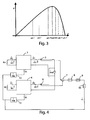
Figure 3 shows three possible pairs of respective operating points on the power-voltage characteristic of the two photovoltaic modules of the system ofFigure 1 ; -
Figure 4 shows a small signal representation of the system ofFigure 1 ; -
Figure 5 shows an equivalent block diagram of the system represented inFigure 4 ; -
Figure 6 shows a schematic block diagram of an alternative preferred embodiment of the electric power generation system according to the invention; -
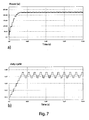
Figure 7 shows the numerical results of simulations on a prior art reference system operating according to the Perturb and Observe technique and comprising a boost converter, whereinFigure 7a represents the time domain behaviour of the power extracted from the photovoltaic module in stable atmospheric conditions, during boost converter power up transient until steady conditions are reached, andFigure 7b shows the corresponding time domain behaviour of the duty cycle of the boost converter switches; -
Figure 8 shows the numerical results of simulations on the system ofFigure 1 related to the extracted power (Figure 8a ) and duty cycle (Figure 8b ) of each converter; -
Figure 9 shows a varying behaviour of the sunlight level S used in simulations carried out on the prior art reference system and on the system ofFigure 1 ; -
Figure 10 shows the numerical results of simulations, under the sunlight conditions ofFigure 9 , related to the behaviour of the power extracted from the photovoltaic module (Figure 10a ) and to the corresponding behaviour of the duty cycle of the boost converter switches (Figure 10b ) of the prior art reference system; -
Figure 11 shows the numerical results of simulations, under the sunlight conditions ofFigure 9 , related to the extracted power (Figure 11 a) and duty cycle (Figure 11 b) of each converter of the system diFigure 1 ; -
Figure 12 shows a comparison of the time domain behaviour of the power extracted from the photovoltaic modules as shown inFigures 10a and11 a; and -
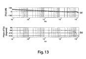
Figure 13 shows the Bode plots of amplitude (Figure 13a ) and phase (Figure 13b ) for two values of Δd of a quantity appearing as summand in denominator of the two closed loop transfer functions of the system ofFigure 1 . - In the Figures, alike elements are indicated by same reference numbers.
- In the following, the invention will be illustrated with reference to stand-alone embodiments employing converters with direct current output and direct current input (dc-dc). However, it should be understood that other embodiments of the invention may be used in applications with connections to an electric energy distribution network (or grid connected), employing different types of power converters, e.g. with alternate current output and direct current input (dc-ac), still remaining within the scope of the present invention.
- Moreover, in the following of the present description and in the claims, every time that it will be said that two components or sections are identical, it should be understood that they are identical within the normal manufacturing tolerances.
- With reference to
Figure 1 , it may be observed that a preferred embodiment of the electric power generation system according to the invention comprises two identical photovoltaic modules A and B, respectively indicated byreference numbers 1 and 2 (it must be considered that, alternatively, blocks 1 and 2 could represent identical sections of a photovoltaic field, that as said before may also consist of single panels or sub-sections of a single panel). The twomodules modules converter 3 and with dB(t) for converter 4). In the following, each pair (1-3 or 2-4) formed by a photovoltaic module and the respective converter will be also indicated as switching photovoltaic source, respectively A or B. - Output nodes of the two
converters Figure 1 ):
- As a consequence, if the values of the output currents iA2 and iB2 are controlled so that they are equal (iA2 = iB2), then the powers provided by the two switching photovoltaic sources A and B assume the same value. Therefore, also the power P extracted from the two
photovoltaic modules dc converters 
dc converters - when the operating voltages vA1 and vB1 of the two
photovoltaic modules - when the operating voltages vA1 and vB1 of the two
photovoltaic modules Figure 2 , are located on opposite sides of the power-voltage characteristic of the twomodules - As it will be explained later, the controller apparatus according to the invention is capable to just give rise to the operation condition shown in
Figure 2 . - The output currents iA2 and iB2 of the two dc-
dc converters subtractor device 7 giving a difference signal (iA2 - iB2) to anamplifier 8 having constant gain k equal to (-1) (in other words, theamplifier 8 operates as inverter for the input signal). In particular, the output signal of the amplifier 8
converters pass filter 9. The output signal of the low-pass filter 9 is, hence, equal to
converters - Finally, the output signal of the low-
pass filter 9 is sent to a Proportional-Integral (or PI)controller 10, the output signal vc(t) of which is sent to a first pulse width (PWM) modulator that generates the periodic signal for controlling theconverter 4 having instant duty cycle dB(t), so that the pulse width of the controlling signal (and, consequently, the instant duty cycle dB(t)) is proportional to the value of the signal vc(t). In particular, the first modulator is made through acomparator 11 at the non-inverting input of which the output signal vc(t) of thePI controller 10 is present and at the inverting input of which a periodic signal sB(t) with sawtooth waveform the peak amplitude of which is VM (with period equal to the switching period of the switches of the converter 4) is present, coming from asuitable generator 12, whereby the duty cycle dB(t) of the switches of theconverter 4 is equal to
- A second modulator PWM generates the periodic signal for controlling the
converter 3 having instant duty cycle dA(t). Also the second modulator is made through acomparator 13 at the inverting input of which a periodic signal sA(t) with sawtooth waveform the peak amplitude of which is VM (with period equal to the switching period of the switches of theconverter 3, identical to the switching period of the converter 4) is present, coming from asuitable generator 14; in particular, the signals sA(t) and sB(t) could come from a sole generator. At the non-inverting input of the comparator 13 a difference signal between the output signal vc(t) of thePI controller 10 and a constant value (VM * Δd), where 0 < Δd < 1, coming from asubtractor device 15, is present; i.e. at the non-inverting input of the comparator 13 a signal equal to (vc(t) - VM * Δd) is present. In other words, at the non-inverting input of thecomparator 13 the signal vc(t) to which cui a negative constant displacement
converter 3 is equal to
- Presence of the
PI controller 10 ensures that its input signal tends to have a dc value equal to zero, i.e.:
- This implies that the dc values of the two output currents of the
converters 
- By indicating with M(d) the conversion ratio between the output voltage and the input voltage of the
converters 3 and 4 (identical to each other), where d is the duty cycle of the switches of these, the input voltages vA1 and vB1 of theconverters 

- The choice of the type of the
converters 
- Since dA(t) is always smaller than dB(t) (see equation [2]), equation [7] demonstrates that M(dA(t)) is always smaller than M(dB(t)), and consequently from equations [5] and [6] it is

- In these conditions, the three situations shown in
Figure 3 with reference to the power-voltage characteristic of thephotovoltaic modules - The first situation is when both the operating points of the two
photovoltaic modules - The second situation is when both the operating points of the two
photovoltaic modules - The third situation is when the operating points of the two
photovoltaic modules modules - In the case of the first situation (vB1' < vA1' < vMPP), power PA extracted from the
module 1 is higher than power PB extracted from themodule 2 and, thanks to the parallel connection of the outputs of theconverters 3 and 4 (vA2 = vB2 = Vout), it is iA2 > iB2. As a consequence, the input signal of thePI controller 10 is lower than zero (since k = -1), and, hence, the output signal vc(t) of thePI controller 10 is a decreasing function of time. On the basis of equations [1], [2] and [7], also dA(t), dB(t), M(dA(t)) and M(dB(t)) are decreasing functions of time. As a consequence, since the output voltage Vout is fixed, both voltages vA1 = vA1' and vB1 = vB1', given by thephotovoltaic modules photovoltaic modules - It is immediate to verify that the case of the second situation (vMPP < vB1'' < vA1'') is mutual to the first one, whereby the operating points of both
photovoltaic modules - The only possible balance situation is the third one (vB1 < vMPP < vA1), wherein voltages vA1 and vB1 given by the
photovoltaic modules PI controller 10 is almost equal to zero and, hence, quantities dA(t), dB(t), M(dA(t)), M(dB(t)), vA1 and vB1 are approximately constant. - It is evident that the choice of the sign of the value of the constant gain k of the
amplifier 8 is related to equation [2]. In fact, if instead of thesubtractor device 15 an adder device were employed (i.e., if the displacement Displacement were positive, instead of negative) and hence duty cycle dA(t) of the switches of theconverter 3 were
Figure 1 , the sign of the constant gain k of theamplifier 8 should be reversed, i.e. it should be:
- As far as the value of the constant Δd, i.e. the value of the modulus of the displacement Displacement, is concerned, in ideal balance conditions, the smaller the modulus Δd of the displacement Displacement, the shorter is the distance of the operating point of each one of the two
photovoltaic modules - The value of the modulus Δd of the displacement Displacement does not only affect efficiency of MPPT tracking under steady conditions, but also the velocity of the whole tracking process (i.e. the velocity in reaching the maximum power point of the
modules 1 and 2) in dynamic conditions. In fact, the larger the value of Δd, the higher is such velocity. Obviously, if the displacement were null (i.e. Δd = 0), in the case of two perfectly equal switching photovoltaic sources A and B such velocity would be equal to zero, in the sense that the system would not be capable to carry out the tracking process. Therefore, the choice of the value of Δd must be made on the basis of a reasonable compromise between efficiency of MPPT tracking under steady conditions and dynamic performance of the MPPT system. Such value may be obtained on the basis of the analysis of the static conversion ratios M(dA(t)) and M(dB(t)) (affecting efficiency under steady conditions) of the used converters and of suitable transfer functions (affecting efficiency of MPPT tracking), as illustrated below. - As far as sizing of the very simple circuitry required by the controller apparatus according to the invention (comprising, in particular, a low-pass filter and a PI controller) is concerned, a small signal representation of the whole system of
Figure 1 , immediately understandable by those skilled in the art, is shown inFigure 4 , where symbols with superimposed angle sign represent small signal variations about the values under steady conditions of the corresponding quantities. - The
photovoltaic modules Figure 1 are represented by resistors. In particular, as described by N. Femia, G. Petrone, G. Spagnuolo, and M. Vitelli in "Optimization of perturb and observe maximum power point tracking method", IEEE Trans. Power Electron., vol. 20, no. 4, pp. 963-973, Jul. 2005, RA and RB are the absolute values of the differential resistances of themodules 

- The values of RA and RB strongly depend on the operating point of the respective photovoltaic modules. In particular, at the maximum power point, it is:


- As described by R. W. Erickson and D. Maksimovic in "Fundamental of Power Electronics", Norwell, MA: Kluwer, 2001, the small signal model of the boost converter may be obtained by carrying out the average and linearising the equations of state of the same boost converter. The equivalent block diagram is shown in
Figure 5 , wherein the transfer functions (in the Laplace domain) have the following expressions:

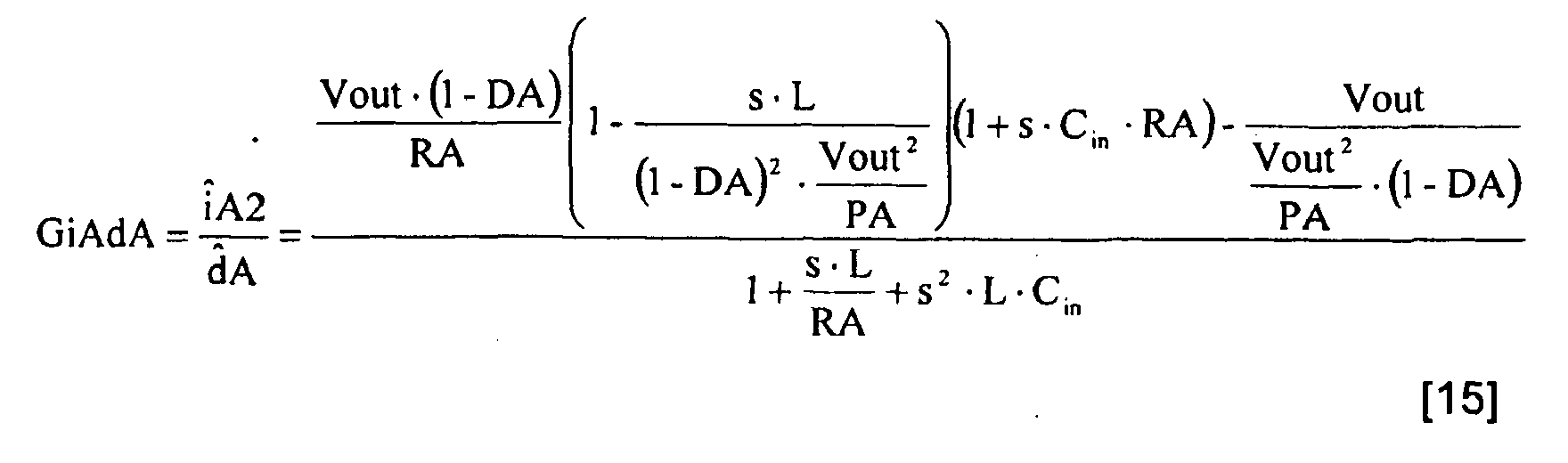

where: - PA is the power extracted from the
module 1 and PB is the power extracted from themodule 2, - L is the value of the inductance of the inductors with which the boost converters (indicated with 3 and 4 in
Figure 1 ) are provided, - Cin is the value of the capacitance of the input capacitors with which the boost converters are provided, and
- DA and DB are the mean values of the duty cycles of the two boost converters.
- The product of the constant gain k of the
amplifier 8, of the transfer function LP(s) of the low-pass filter 9, of the transfer function PI(s) of thePI controller 10 and of thegain 1/VM of the modulator PWM is indicated with W(s):
- The closed loop transfer functions WiBv and WiAv of the two switching photovoltaic sources A and B represented in
Figure 5 are:

- In order to make the closed loop system stable, with an adequate phase margin and a sufficiently high crossover frequency, the transfer function LP(s)*PI(s) must satisfy certain constraints. In this regard, in order to ensure system stability, the phase margin test (described by R. W. Erickson and D. Maksimovic in "Fundamental of Power Electronics", Norwell, MA: Kluwer, 2001) may be applied to the quantity T(s) appearing in denominator of both the closed loop transfer functions [18] and [19]. This entails that, in order that the closed loop transfer functions [18] and [19] do not contain any pole in the right half-plane of the Laplace domain (ensuring system stability), the phase margin of the quantity

- Other embodiments of the controller apparatus according to the invention may comprise, instead of the PI controller, a Proportional-Integral-Derivative (or PID) controller, that allows an improvement of the phase margin.
- The system illustrated so far is a stand-alone system. However, it must be understood that, as already said above, that the invention is also applicable to grid-connected photovoltaic systems.
- Other embodiments of the system according to the invention may provide a mutual configuration of the connections between the switching photovoltaic sources A and B, with respect to the one shown in
Figure 1 . In this case, as shown inFigure 6 , the output nodes of theconverters subtractor device 7 would give to theamplifier 8 the difference signal between the two detected signals of the voltages vA2 and vB2. The operation principle of the system would remain unchanged, whereas sizing of the control circuitry will be carried out on the basis of the mutuality principle, i.e. by replacing voltages with currents and vice versa, and by considering the transfer functions as functions of voltages instead of the transfer functions as functions of currents. - The inventors have carried out some simulations of the system of
Figure 1 for checking its performance. In particular, in order to demonstrate the high performance obtainable through the invention, the Perturb & Observe, or P&O, technique described by N. Femia, G. Petrone, G. Spagnuolo, and M. Vitelli in "Optimization of perturb and observe maximum power point tracking method', IEEE Trans. Power Electron., vol. 20, no. 4, pp. 963-973, Jul. 2005, and by N. Femia, D. Granozio, G. Petrone, G. Spagnuolo, and M. Vitelli in "A predictive and adaptive MPPT perturb and observe method', IEEE Trans. Aerosp. Electron. Syst., vol. 43, no. 3, pp. 934-950, Jul. 2007, has been used as reference technique. Such P&O technique, as said before, is easily implementable and, if properly designed, is capable to lead to very high values of MPPT efficiency. In this regard, in the simulations of both systems, both the controller apparatus according to the invention and the controller apparatus operating according to the P&O technique have been optimised, in order to render their comparison significant. Therefore, the parameters of the system ofFigure 1 are chosen as previously discussed, whereas the two parameters involved in the application of the P&O technique (i.e. the amplitude ΔdP&O of the duty cycle perturbation and the time interval Ta between two consecutive duty cycle perturbations) have been chosen as explained by N. Femia, G. Petrone, G. Spagnuolo, and M. Vitelli in "Optimization of perturb and observe maximum power point tracking method", IEEE Trans. Power Electron., vol. 20, no. 4, pp. 963-973, Jul. 2005. In particular, for such parameters, the following sets of values have been chosen: - for the system of
Figure 1 : Δd = 0,02; VM = 1; LP(s)= 1/(1+s*1,4/6280+s2/62802); PI(s)=(1+s*5*10-5)/(s*5*10-7); - for the P&O system: Ta = 4 ms; ΔdP&O = 0,02.
- The value of the modulus Δd of the negative displacement Displacement has been chosen equal to the value of the perturbation amplitude ΔdP&O so that, under steady conditions, if such value (Δd = ΔdP&O ) is rather small, the two systems should approximately give the same values of efficiency of MPPT tracking.
- Actually, as described in the just mentioned paper by Femia et al., with a properly sized P&O system, under steady conditions, the operating voltage of a given photovoltaic source oscillates by assuming only three different values located in the proximity of the voltage vMPP corresponding to the maximum power point: the voltage vL on the left of the maximum power point (vL = vMPP - vout·ΔdP&O ), the voltage vC ≈ vMPP, and the voltage vR on the right of the maximum power point (vR = vMPP + vout·ΔdP&O ), where vL < vC < vR.
- In the system according to the invention di
Figure 1 , under steady conditions, the operating voltage of eachphotovoltaic module - Therefore, from the point of view of the efficiency, the fact that the voltages vA and vB given by the two
photovoltaic modules Figure 1 are closer to the voltage vMPP corresponding to the maximum power point with respect to the voltages vL and vR of the P&O system is more or less compensated by the fact that in the P&O technique a third operating point exists that is approximately coinciding with the maximum power point. - In this regard, the photovoltaic modules considered in the simulations are Sunmodule SW225 poly modules made of 60 cells 156*156 mm2 of polycrystalline silicon. The electrical characteristics of such modules in Standard Test Conditions, i.e. for sunlight level S equal to 1000 W/m2, cell temperature equal to 25°C, and air mass (AM) equal to 1,5, are as follows:
- open circuit voltage Voc 36,8 V,
- short circuit current Isc = 8,17 A,
- maximum power point voltage vMPP = 29,5 V,
- maximum power point current iMPP = 7,63 A,
- nominal operating cell temperatures NOCT = 46 °C.
- In the simulation, a fixed mean value of room temperature Tamb, equal to 25°C, has been considered. Moreover, the circuit and boost converter operation parameters (identical for the system of
Figure 1 and for the P&O system) are the following: output inductance L = 180 pH, output voltage Vout = 40 V, switching frequency fs = 50 kHz, and input capacitance Cin = 120 µF. - In
Figure 7 , the numerical results of the simulations of the P&O system are shown.Figure 7a represents the time domain behaviour of the power extracted from the photovoltaic module in stable atmospheric conditions (S=1000 W/m2, Tamb = 25°C), during the boost converter power up transient until steady conditions are reached. Differently,Figure 7b shows the corresponding time domain behaviour of the duty cycle of the boost converter switches. - The graph shown in
Figure 8 refer to the corresponding quantities for the system ofFigure 1 . Actually,Figures 8a and 8b show the extracted power and the duty cycle for both the switching photovoltaic sources A and B, even if the waveforms ofFigure 8a are not easily distinguishable, since they are substantially superimposed. - By examining
Figures 7 and8 ,it is evident that both the system ofFigure 1 and the P&O system are capable to lead, under steady conditions, to a power extracted from ea ch mo dule very close to the maximum power PMMP = 225 W. However, by comparing such Figures, the higher tracking velocity of the system ofFigure 1 is further evident. This aspect represents a further advantage offered by the invention with respect to prior art MPPT tracking techniques. - Further numerical simulations have been carried out by taking time variable atmospheric conditions into account. In particular, by way of example, the behaviour of the sunlight level S shown in
Figure 9 has been considered. - In
Figure 10 the numerical results obtained through the P&O system are shown. In particular,Figure 10a shows the behaviour of the power extracted from the photovoltaic module, whereasFigure 10b shows the corresponding behaviour of the duty cycle of the boost converter switches. - Differently, the graphs shown in
Figure 11 refer to the corresponding waveforms obtained with the system ofFigure 1 . Also inFigures 11 a and 11b the extracted power and the duty cycle for both the switching photovoltaic sources A and B are actually shown, even if the two waveforms ofFigure 11a are not easily distinguishable, since they are substantially superimposed. -
Figure 12 shows a comparison of the time domain behaviour of the powers extracted from the photovoltaic modules as shown inFigures 10a and11a . Such comparison clearly highlights the higher tracking velocity obtained through the system ofFigure 1 with respect to the P&O system. - As said before, the larger the value of the modulus Δd of the displacement Displacement, the higher is the velocity of the MPPT tracking process. In this regard,
Figure 13 shows the Bode plots of amplitude (Figure 13a ) and phase (Figure 13b ) of the quantity T(s) represented by equation [20] in two cases: for a modulus Δd = 0,02 (thick line), and for a modulus Δd = 0,002 (thin line). As shown inFigure 13b , the value of the modulus Δd of the displacement Displacement has a neglectable effect on the phase plots (which are approximately coinciding). However, as shown inFigure 13a , the variation of the value of the displacement modulus Δd causes an evident variation of the crossover frequency in the amplitude plots: the larger the value of the displacement modulus Δd, the higher will be the crossover frequency and, as a consequence, the shorter will be the system response time. - Although it may be implemented also with digital circuitry, however it deserves to be highlighted once more that the controller apparatus according to the invention may be advantageously implemented with purely analog circuitry.
- The present invention has been described, by way of illustration and not by way of limitation, according its preferred embodiments, but it should be understood that those skilled in the art can make variations and/or changes, without so departing from the related scope of protection, as defined by the enclosed claims.
Claims (14)
- System comprising a controller apparatus with maximum power point tracking, or MPPT, and an electric power generation system based on photovoltaic sources, the controller apparatus controlling the electric power generation system, the electric power generation system comprising two identical sections (1, 2) of a photovoltaic field, connected to two respective identical power converters (3, 4) with direct current input, each converter (3, 4) comprising switching means capable to periodically connect the input to the output of the same converter (3, 4), the two converters (3, 4) being controlled by two respective periodic signals for controlling the switching means which are generated by the controller apparatus, the output of each converter being capable to provide a respective pair of output electrical quantities consisting of an output voltage (vA2; vB2) and an output current (iA2; iB2), the outputs of the two converters (3, 4) being connected in such a configuration to have an identical first output electrical quantity (vA2, vB2; iA2, iB2) selected from said respective pair of output electrical quantities, characterised in that the controller apparatus comprises:- a first sensor (5) for detecting a second output electrical quantity (iA2; vA2) selected from the pair of output electrical quantities of a first one of said two converters (3), for giving a first detection signal,- a second sensor (6) for detecting a second output electrical quantity (iB2; vB2) selected from the pair of output electrical quantities of a second one of said two converters (4), for giving a second detection signal,- subtractor means (7) capable to receive said first and second detection signals and to generate a difference signal (iA2- iB2; vA2-vB2) between the second output electrical quantity (iA2; vA2) of the first converter (3) and the second output electrical quantity (iB2; vB2) of the second converter (4),- amplifier means (8) capable to receive said difference signal (iA2-iB2; vA2- vB2) and to amplify the same by a constant gain k, outputting an amplified difference signal,- low-pass filter means (9) capable to receive and to filter said amplified difference signal, for outputting a filtered amplified difference signal,- controller means (10) capable to receive said filtered amplified difference signal and to carry out a proportional action and an integral action on the same, for outputting a processed signal vc(t),- first generator means (11, 12) capable to receive said processed signal vc(t) and to generate a first one of said two controlling periodic signals having an instant duty cycle dB(t) proportional to said processed signal vc(t) by a constant equal to 1/VM, whereby
 - adder means (15) capable to receive said processed signal and to add to it a constant displacement (Displacement) having modulus VM * Δd, with Δd ranging from 0 to 1:
 - second generator means (13, 14) capable to receive said displaced processed signal and to generate a second one of said two controlling periodic signals having an instant duty cycle dA(t) proportional to said displaced processed signal, for outputting said second controlling periodic signal capable to control the first converter (3),said constant gain k and said constant displacement (Displacement) having the same sign.
 - System according to claim 1, characterised in that said controller means (10) are further capable to carry out a derivative action on said filtered amplified difference signal.
- System according to claim 1 or 2, characterised in that said first generator means comprises first pulse width modulator (PWM) means, preferably comprising first comparator means (11) having a non-inverting input, capable to receive said processed signal, and an inverting input, capable to receive a periodic signal with sawtooth waveform the peak amplitude of which is VM and that is generated by a corresponding generator (12), said first comparator means (11) giving said first controlling periodic signal.
- System according to any one of the preceding claims, characterised in that said second generator means comprises second pulse width modulator (PWM) means, preferably comprising second comparator means (13) having a non-inverting input, capable to receive said displaced processed signal, and an inverting input, capable to receive a periodic signal with sawtooth waveform the peak amplitude of which is VM and it is generated by a corresponding generator (14), said second comparator means (13) giving said first controlling periodic signal.
- System according to any one of the preceding claims, characterised in that the outputs of the two converters (3, 4) are connected in parallel, so as to have an identical output voltage (vA2; vB2), whereby:- said first output electrical quantity of the two converters (3, 4) is the respective output voltage (vA2; vB2),- said second output electrical quantity of the first one (3) of said two converters is the output current (iA2) of the first one (3) of said two converters,- said second output electrical quantity of the second one (4) of said two converters is the output current (i82) of the second one (4) of said two converters,- the first sensor (5) detecting the output current (iA2) of the first one (3) of said two converters, and- the second sensor (6) detecting the output current (iB2) of the second one (4) of said two converters.
- System according to any one of claims 1 to 4, characterised in that the outputs of the two converters (3, 4) are connected in series, so as to have an identical output current (iA2; iB2), whereby:- said first output electrical quantity of the two converters (3, 4) is the respective output current (iA2; iB2),- said second output electrical quantity of the first one (3) of said two converters is the output voltage (vA2) of the first one (3) of said two converters,- said second output electrical quantity of the second one (4) of said two converters is the output voltage (vB2) of the second one (4) of said two converters,- the first sensor (5) detecting the output voltage (vA2) of the first one (3) of said two converters, and- the second sensor (6) detecting the output voltage (vB2) of the second one (4) of said two converters.
- System according to any one of the preceding claims, characterised in that each one of said two identical sections comprises a photovoltaic module (1, 2).
- System according to any one of the preceding claims, characterised in that it is stand-alone.
- System according to claim 8, characterised in that said two power converters (3, 4) have direct current output, said two converters (3, 4) being preferably boost converters, more preferably with continuous conduction operation mode or CCM (Continuous Conduction Mode).
- System according to any one of claims 1 to 7, characterised in that it is connected to an electric energy distribution network (grid connected), said two power converters (3, 4) having alternate current output.
- Controlling method with MPPT tracking for controlling an electric power generation system based on photovoltaic sources, the system comprising two identical sections (1, 2) of a photovoltaic field, connected to two respective identical power converters (3, 4) with direct current input, each converter (3, 4) comprising switching means capable to periodically connect the input to the output of the same converter (3, 4), the two converters (3, 4) being controlled by two respective periodic signals for controlling the switching means, the output of each converter providing a respective pair of output electrical quantities consisting of an output voltage (vA2; vB2) and an output current (iA2; iB2), the outputs of the two converters (3, 4) being connected in such a configuration to have an identical first output electrical quantity (vA2, vB2; iA2, iB2) selected from said respective pair of output electrical quantities, the method being characterised in that it further comprises the following steps:A. detecting a second output electrical quantity (iA2; vA2) selected from the pair of output electrical quantities of a first one of said two converters (3), obtaining a first detection signal,B. detecting a second output electrical quantity (iB2; vB2) selected from the pair of output electrical quantities of a second one of said two converters (4), obtaining a second detection signal,C. generating a difference signal (iA2- iB2; vA2- vB2) between the second output electrical quantity (iA2; vA2) of the first converter (3) and the second output electrical quantity (iB2; vB2) of the second converter (4) on the basis of said first and second current detection signals,D. amplifying said difference signal (iA2- iB2) by a constant gain k, obtaining an amplified difference signal,E. filtering said amplified difference signal, obtaining a filtered amplified difference signal,F. carrying out a proportional action and an integral action on said filtered amplified difference signal, obtaining a processed signal vc(t),G. generating a first one of said two controlling periodic signals having an instant duty cycle dB(t) proportional to said processed signal vc(t) by a constant equal to 1/VM, whereby
 H. adding to said processed signal a constant displacement (Displacement) having modulus VM * Δd, with Δd ranging from 0 to 1:
 I. generating a second one of said two controlling periodic signals having an instant duty cycle dA(t) proportional to said displaced processed signal, obtaining said second controlling periodic signal capable to control the first converter (3),said constant gain k and said constant displacement (Displacement) having the same sign.
 - Method according to claim 11, characterised in that step F further carries out a derivative action on said filtered amplified difference signal.
- Method according to claim 11 or 12, characterised in that the outputs of the two converters (3, 4) are connected in parallel, so as to have an identical output voltage (vA2; vB2), whereby:- said first output electrical quantity of the two converters (3, 4) is the respective output voltage (vA2; vB2),- said second output electrical quantity of the first one (3) of said two converters is the output current (iA2) of the first one (3) of said two converters,- said second output electrical quantity of the second one (4) of said two converters is the output current (iB2) of the second one (4) of said two converters,- the method detects in step A the output current (iA2) of the first one (3) of said two converters, and- the method detects in step B the output current (iB2) of the second one (4) of said two converters.
- Method according to claim 11 or 12, characterised in that the outputs of the two converters (3, 4) are connected in series, so as to have an identical output current (iA2; iB2), whereby:- said first output electrical quantity of the two converters (3, 4) is the respective output current (iA2; iB2),- said second output electrical quantity of the first one (3) of said two converters is the output voltage (vA2) of the first one (3) of said two converters,- said second output electrical quantity of the second one (4) of said two converters is the output voltage (vB2) of the second one (4) of said two converters,- the method detects in step A the output voltage (vA2) of the first one (3) of said two converters, and- the method detects in step B the output voltage (vB2) of the second one (4) of said two converters.
Applications Claiming Priority (2)
| Application Number | Priority Date | Filing Date | Title |
|---|---|---|---|
| ITRM2009A000193A IT1393858B1 (en) | 2009-04-24 | 2009-04-24 | CONTROLLER EQUIPMENT FOLLOWING THE MAXIMUM POWER POINT OF AN ELECTRIC POWER GENERATION SYSTEM BASED ON PHOTOVOLTAIC SOURCES, CONTROL METHOD AND RELATIVE ELECTRIC POWER GENERATION SYSTEM. |
| PCT/IT2010/000167 WO2010122589A1 (en) | 2009-04-24 | 2010-04-19 | Controller apparatus with maximum power point tracking for controlling an electric power generation system based on photovoltaic sources, controlling method and related electric power generation system |
Publications (2)
| Publication Number | Publication Date |
|---|---|
| EP2422255A1 EP2422255A1 (en) | 2012-02-29 |
| EP2422255B1 true EP2422255B1 (en) | 2015-02-25 |
Family
ID=42244624
Family Applications (1)
| Application Number | Title | Priority Date | Filing Date |
|---|---|---|---|
| EP20100727963 Not-in-force EP2422255B1 (en) | 2009-04-24 | 2010-04-19 | Controller apparatus with maximum power point tracking for controlling an electric power generation system based on photovoltaic sources, controlling method and related electric power generation system |
Country Status (5)
| Country | Link |
|---|---|
| US (1) | US8829721B2 (en) |
| EP (1) | EP2422255B1 (en) |
| CA (1) | CA2759669A1 (en) |
| IT (1) | IT1393858B1 (en) |
| WO (1) | WO2010122589A1 (en) |
Cited By (1)
| Publication number | Priority date | Publication date | Assignee | Title |
|---|---|---|---|---|
| CN104881077A (en) * | 2015-04-23 | 2015-09-02 | 燕宏伟 | Tracking control method of maximum power point in photovoltaic system |
Families Citing this family (17)
| Publication number | Priority date | Publication date | Assignee | Title |
|---|---|---|---|---|
| US9006930B2 (en) * | 2010-07-08 | 2015-04-14 | Delta Electronics Inc. | Power supply having converters with serially connected inputs and parallel connected outputs |
| US8774007B2 (en) * | 2011-03-23 | 2014-07-08 | Sunpower Corporation | Apparatus and method for data communication in an energy distribution network |
| TWI438602B (en) | 2011-12-02 | 2014-05-21 | Ind Tech Res Inst | Maximum power point tracking controllers, maximum power point tracking systems and maximum power point tracking methods |
| TWI470396B (en) | 2013-06-26 | 2015-01-21 | 財團法人工業技術研究院 | Power point tracking method and device |
| US9330424B2 (en) * | 2013-06-28 | 2016-05-03 | Vmware, Inc. | Power management analysis and modeling for distributed computer systems |
| US9461535B2 (en) * | 2013-12-30 | 2016-10-04 | King Fahd University Of Petroleum And Minerals | Photovoltaic systems with maximum power point tracking controller |
| US9847645B2 (en) * | 2015-02-03 | 2017-12-19 | King Fahd University Of Petroleum And Minerals | Neuro-fuzzy control system for grid-connected photovoltaic systems |
| KR102322366B1 (en) * | 2017-03-02 | 2021-11-04 | 현대자동차주식회사 | Solar cell system and control method thereof |
| CN108494300A (en) * | 2018-04-13 | 2018-09-04 | 昆明理工大学 | A kind of maximal power tracing sliding-mode control based on magneto alternator disturbance observer |
| CN111404141B (en) * | 2020-03-30 | 2023-04-25 | 湖南大学 | Control method and system for suppressing output oscillation of photovoltaic converter in DC power grid |
| CN112987839B (en) * | 2021-03-01 | 2022-07-15 | 哈尔滨工程大学 | A photovoltaic cell maximum power point tracking control circuit and method |
| EP4246806B9 (en) * | 2022-03-15 | 2025-06-25 | INVENTVM Semiconductor SRL | Adaptive control of capacitive load |
| CN115566715A (en) * | 2022-03-29 | 2023-01-03 | 江苏方程电力科技有限公司 | Three-phase converter non-alternating voltage sensor prediction control method |
| EP4500655A4 (en) | 2022-03-31 | 2025-05-07 | Optivolt Labs, Inc. | System and method for regulating power output of multiple solar substrings |
| CN115328263B (en) * | 2022-07-13 | 2024-05-03 | 南京理工大学 | MPPT method of fuel cell based on double-sliding-mode-surface self-adaptive equivalent sliding mode control |
| CN115189410A (en) * | 2022-08-17 | 2022-10-14 | 易事特储能科技有限公司 | Distributed optical storage device and control method thereof |
| CN116931646B (en) * | 2023-06-26 | 2026-02-24 | 扬州大学 | Photovoltaic MPPT control system based on fuzzy-PID two-stage control algorithm |
Family Cites Families (1)
| Publication number | Priority date | Publication date | Assignee | Title |
|---|---|---|---|---|
| US9088178B2 (en) * | 2006-12-06 | 2015-07-21 | Solaredge Technologies Ltd | Distributed power harvesting systems using DC power sources |
-
2009
- 2009-04-24 IT ITRM2009A000193A patent/IT1393858B1/en active
-
2010
- 2010-04-19 CA CA2759669A patent/CA2759669A1/en not_active Abandoned
- 2010-04-19 EP EP20100727963 patent/EP2422255B1/en not_active Not-in-force
- 2010-04-19 US US13/266,073 patent/US8829721B2/en not_active Expired - Fee Related
- 2010-04-19 WO PCT/IT2010/000167 patent/WO2010122589A1/en not_active Ceased
Cited By (1)
| Publication number | Priority date | Publication date | Assignee | Title |
|---|---|---|---|---|
| CN104881077A (en) * | 2015-04-23 | 2015-09-02 | 燕宏伟 | Tracking control method of maximum power point in photovoltaic system |
Also Published As
| Publication number | Publication date |
|---|---|
| US20120038217A1 (en) | 2012-02-16 |
| EP2422255A1 (en) | 2012-02-29 |
| ITRM20090193A1 (en) | 2010-10-25 |
| US8829721B2 (en) | 2014-09-09 |
| CA2759669A1 (en) | 2010-10-28 |
| IT1393858B1 (en) | 2012-05-11 |
| WO2010122589A1 (en) | 2010-10-28 |
Similar Documents
| Publication | Publication Date | Title |
|---|---|---|
| US8829721B2 (en) | Controller apparatus with maximum power point tracking for controlling an electric power generation system based on photovoltaic sources, controlling method and related electric power generation system | |
| Killi et al. | Modified perturb and observe MPPT algorithm for drift avoidance in photovoltaic systems | |
| Killi et al. | An adaptive voltage-sensor-based MPPT for photovoltaic systems with SEPIC converter including steady-state and drift analysis | |
| Femia et al. | A new analog MPPT technique: TEODI | |
| CN104035476B (en) | Based on the maximum power point tracing method of output voltage frequency stepping disturbance | |
| Lešo et al. | Survey of control methods for DC-DC converters | |
| Surya et al. | Review and comparison of DC-DC converters for maximum power point tracking system in standalone photovoltaic (PV) module | |
| Levron et al. | Nonlinear control design for the photovoltaic isolated-port architecture with submodule integrated converters | |
| CN116540830B (en) | A method, system and device for flexible control of output power of photovoltaic power generation system | |
| Riawan et al. | Analysis and design of a solar charge controller using cuk converter | |
| Sangeetha et al. | Design and implementation of SEPIC converter based PV system using modified incremental conductance algorithm | |
| Manoharan et al. | Power conditioning for a small-scale PV system with charge-balancing integrated micro-inverter | |
| Bae et al. | New MPPT control strategy for two-stage grid-connected photovoltaic power conditioning system | |
| Bae et al. | New control strategy for 2-stage utility-connected photovoltaic power conditioning system with a low cost digital processor | |
| Narasimhulu et al. | Performance analysis of single-stage PV connected three-phase grid system under steady state and dynamic conditions | |
| Liqun et al. | A variable voltage MPPT control method for photovoltaic generation system | |
| Chen et al. | DC bus regulation strategy for grid-connected PV power generation system | |
| Chen et al. | Progressive smooth transition for four-switch buck-boost converter in photovoltaic applications | |
| Wen et al. | Differential power processing based photovoltaic power systems: A review | |
| Vijayakumari et al. | Power angle control of a single phase grid connected photovoltaic inverter for controlled power transfer | |
| Azeem et al. | Design and analysis of packed U-cell and SEPIC converter based solar PV system for grid connection | |
| Munisekhar et al. | The fastest MPPT tracking algorithm for a PV array fed BLDC motor driven air conditioning system | |
| Anandhakumar et al. | Integration of Modified Luo Converter and ANFIS MPPT in Grid-Tied Photovoltaic Systems | |
| Elgendy et al. | Dynamic behaviour of hill-climbing MPPT algorithms at low perturbation rates | |
| CN104423414B (en) | A kind of control method, device and control circuit and electricity generation system |
Legal Events
| Date | Code | Title | Description |
|---|---|---|---|
| PUAI | Public reference made under article 153(3) epc to a published international application that has entered the european phase |
Free format text: ORIGINAL CODE: 0009012 |
|
| 17P | Request for examination filed |
Effective date: 20111111 |
|
| AK | Designated contracting states |
Kind code of ref document: A1 Designated state(s): AT BE BG CH CY CZ DE DK EE ES FI FR GB GR HR HU IE IS IT LI LT LU LV MC MK MT NL NO PL PT RO SE SI SK SM TR |
|
| DAX | Request for extension of the european patent (deleted) | ||
| GRAP | Despatch of communication of intention to grant a patent |
Free format text: ORIGINAL CODE: EPIDOSNIGR1 |
|
| INTG | Intention to grant announced |
Effective date: 20141010 |
|
| GRAS | Grant fee paid |
Free format text: ORIGINAL CODE: EPIDOSNIGR3 |
|
| GRAA | (expected) grant |
Free format text: ORIGINAL CODE: 0009210 |
|
| AK | Designated contracting states |
Kind code of ref document: B1 Designated state(s): AT BE BG CH CY CZ DE DK EE ES FI FR GB GR HR HU IE IS IT LI LT LU LV MC MK MT NL NO PL PT RO SE SI SK SM TR |
|
| REG | Reference to a national code |
Ref country code: GB Ref legal event code: FG4D |
|
| REG | Reference to a national code |
Ref country code: CH Ref legal event code: EP |
|
| REG | Reference to a national code |
Ref country code: IE Ref legal event code: FG4D |
|
| REG | Reference to a national code |
Ref country code: DE Ref legal event code: R096 Ref document number: 602010022539 Country of ref document: DE Effective date: 20150409 |
|
| REG | Reference to a national code |
Ref country code: AT Ref legal event code: REF Ref document number: 712484 Country of ref document: AT Kind code of ref document: T Effective date: 20150415 |
|
| REG | Reference to a national code |
Ref country code: NL Ref legal event code: VDEP Effective date: 20150225 |
|
| REG | Reference to a national code |
Ref country code: AT Ref legal event code: MK05 Ref document number: 712484 Country of ref document: AT Kind code of ref document: T Effective date: 20150225 |
|
| REG | Reference to a national code |
Ref country code: LT Ref legal event code: MG4D |
|
| PG25 | Lapsed in a contracting state [announced via postgrant information from national office to epo] |
Ref country code: HR Free format text: LAPSE BECAUSE OF FAILURE TO SUBMIT A TRANSLATION OF THE DESCRIPTION OR TO PAY THE FEE WITHIN THE PRESCRIBED TIME-LIMIT Effective date: 20150225 Ref country code: SE Free format text: LAPSE BECAUSE OF FAILURE TO SUBMIT A TRANSLATION OF THE DESCRIPTION OR TO PAY THE FEE WITHIN THE PRESCRIBED TIME-LIMIT Effective date: 20150225 Ref country code: ES Free format text: LAPSE BECAUSE OF FAILURE TO SUBMIT A TRANSLATION OF THE DESCRIPTION OR TO PAY THE FEE WITHIN THE PRESCRIBED TIME-LIMIT Effective date: 20150225 Ref country code: NO Free format text: LAPSE BECAUSE OF FAILURE TO SUBMIT A TRANSLATION OF THE DESCRIPTION OR TO PAY THE FEE WITHIN THE PRESCRIBED TIME-LIMIT Effective date: 20150525 Ref country code: LT Free format text: LAPSE BECAUSE OF FAILURE TO SUBMIT A TRANSLATION OF THE DESCRIPTION OR TO PAY THE FEE WITHIN THE PRESCRIBED TIME-LIMIT Effective date: 20150225 Ref country code: FI Free format text: LAPSE BECAUSE OF FAILURE TO SUBMIT A TRANSLATION OF THE DESCRIPTION OR TO PAY THE FEE WITHIN THE PRESCRIBED TIME-LIMIT Effective date: 20150225 |
|
| PG25 | Lapsed in a contracting state [announced via postgrant information from national office to epo] |
Ref country code: LV Free format text: LAPSE BECAUSE OF FAILURE TO SUBMIT A TRANSLATION OF THE DESCRIPTION OR TO PAY THE FEE WITHIN THE PRESCRIBED TIME-LIMIT Effective date: 20150225 Ref country code: GR Free format text: LAPSE BECAUSE OF FAILURE TO SUBMIT A TRANSLATION OF THE DESCRIPTION OR TO PAY THE FEE WITHIN THE PRESCRIBED TIME-LIMIT Effective date: 20150526 Ref country code: AT Free format text: LAPSE BECAUSE OF FAILURE TO SUBMIT A TRANSLATION OF THE DESCRIPTION OR TO PAY THE FEE WITHIN THE PRESCRIBED TIME-LIMIT Effective date: 20150225 Ref country code: IS Free format text: LAPSE BECAUSE OF FAILURE TO SUBMIT A TRANSLATION OF THE DESCRIPTION OR TO PAY THE FEE WITHIN THE PRESCRIBED TIME-LIMIT Effective date: 20150625 |
|
| PG25 | Lapsed in a contracting state [announced via postgrant information from national office to epo] |
Ref country code: NL Free format text: LAPSE BECAUSE OF FAILURE TO SUBMIT A TRANSLATION OF THE DESCRIPTION OR TO PAY THE FEE WITHIN THE PRESCRIBED TIME-LIMIT Effective date: 20150225 |
|
| PG25 | Lapsed in a contracting state [announced via postgrant information from national office to epo] |
Ref country code: CZ Free format text: LAPSE BECAUSE OF FAILURE TO SUBMIT A TRANSLATION OF THE DESCRIPTION OR TO PAY THE FEE WITHIN THE PRESCRIBED TIME-LIMIT Effective date: 20150225 Ref country code: EE Free format text: LAPSE BECAUSE OF FAILURE TO SUBMIT A TRANSLATION OF THE DESCRIPTION OR TO PAY THE FEE WITHIN THE PRESCRIBED TIME-LIMIT Effective date: 20150225 Ref country code: SK Free format text: LAPSE BECAUSE OF FAILURE TO SUBMIT A TRANSLATION OF THE DESCRIPTION OR TO PAY THE FEE WITHIN THE PRESCRIBED TIME-LIMIT Effective date: 20150225 Ref country code: DK Free format text: LAPSE BECAUSE OF FAILURE TO SUBMIT A TRANSLATION OF THE DESCRIPTION OR TO PAY THE FEE WITHIN THE PRESCRIBED TIME-LIMIT Effective date: 20150225 Ref country code: RO Free format text: LAPSE BECAUSE OF FAILURE TO SUBMIT A TRANSLATION OF THE DESCRIPTION OR TO PAY THE FEE WITHIN THE PRESCRIBED TIME-LIMIT Effective date: 20150225 |
|
| REG | Reference to a national code |
Ref country code: DE Ref legal event code: R097 Ref document number: 602010022539 Country of ref document: DE |
|
| PG25 | Lapsed in a contracting state [announced via postgrant information from national office to epo] |
Ref country code: MC Free format text: LAPSE BECAUSE OF FAILURE TO SUBMIT A TRANSLATION OF THE DESCRIPTION OR TO PAY THE FEE WITHIN THE PRESCRIBED TIME-LIMIT Effective date: 20150225 Ref country code: PL Free format text: LAPSE BECAUSE OF FAILURE TO SUBMIT A TRANSLATION OF THE DESCRIPTION OR TO PAY THE FEE WITHIN THE PRESCRIBED TIME-LIMIT Effective date: 20150225 Ref country code: LU Free format text: LAPSE BECAUSE OF FAILURE TO SUBMIT A TRANSLATION OF THE DESCRIPTION OR TO PAY THE FEE WITHIN THE PRESCRIBED TIME-LIMIT Effective date: 20150419 |
|
| REG | Reference to a national code |
Ref country code: CH Ref legal event code: PL |
|
| PLBE | No opposition filed within time limit |
Free format text: ORIGINAL CODE: 0009261 |
|
| STAA | Information on the status of an ep patent application or granted ep patent |
Free format text: STATUS: NO OPPOSITION FILED WITHIN TIME LIMIT |
|
| GBPC | Gb: european patent ceased through non-payment of renewal fee |
Effective date: 20150525 |
|
| REG | Reference to a national code |
Ref country code: IE Ref legal event code: MM4A |
|
| PG25 | Lapsed in a contracting state [announced via postgrant information from national office to epo] |
Ref country code: LI Free format text: LAPSE BECAUSE OF NON-PAYMENT OF DUE FEES Effective date: 20150430 Ref country code: CH Free format text: LAPSE BECAUSE OF NON-PAYMENT OF DUE FEES Effective date: 20150430 |
|
| REG | Reference to a national code |
Ref country code: FR Ref legal event code: ST Effective date: 20151231 |
|
| 26N | No opposition filed |
Effective date: 20151126 |
|
| PG25 | Lapsed in a contracting state [announced via postgrant information from national office to epo] |
Ref country code: FR Free format text: LAPSE BECAUSE OF NON-PAYMENT OF DUE FEES Effective date: 20150430 Ref country code: SI Free format text: LAPSE BECAUSE OF FAILURE TO SUBMIT A TRANSLATION OF THE DESCRIPTION OR TO PAY THE FEE WITHIN THE PRESCRIBED TIME-LIMIT Effective date: 20150225 |
|
| PG25 | Lapsed in a contracting state [announced via postgrant information from national office to epo] |
Ref country code: GB Free format text: LAPSE BECAUSE OF NON-PAYMENT OF DUE FEES Effective date: 20150525 Ref country code: IE Free format text: LAPSE BECAUSE OF NON-PAYMENT OF DUE FEES Effective date: 20150419 |
|
| PG25 | Lapsed in a contracting state [announced via postgrant information from national office to epo] |
Ref country code: BE Free format text: LAPSE BECAUSE OF FAILURE TO SUBMIT A TRANSLATION OF THE DESCRIPTION OR TO PAY THE FEE WITHIN THE PRESCRIBED TIME-LIMIT Effective date: 20150225 |
|
| PGFP | Annual fee paid to national office [announced via postgrant information from national office to epo] |
Ref country code: DE Payment date: 20160421 Year of fee payment: 7 |
|
| PGFP | Annual fee paid to national office [announced via postgrant information from national office to epo] |
Ref country code: IT Payment date: 20160412 Year of fee payment: 7 |
|
| PG25 | Lapsed in a contracting state [announced via postgrant information from national office to epo] |
Ref country code: MT Free format text: LAPSE BECAUSE OF FAILURE TO SUBMIT A TRANSLATION OF THE DESCRIPTION OR TO PAY THE FEE WITHIN THE PRESCRIBED TIME-LIMIT Effective date: 20150225 |
|
| PG25 | Lapsed in a contracting state [announced via postgrant information from national office to epo] |
Ref country code: SM Free format text: LAPSE BECAUSE OF FAILURE TO SUBMIT A TRANSLATION OF THE DESCRIPTION OR TO PAY THE FEE WITHIN THE PRESCRIBED TIME-LIMIT Effective date: 20150225 Ref country code: HU Free format text: LAPSE BECAUSE OF FAILURE TO SUBMIT A TRANSLATION OF THE DESCRIPTION OR TO PAY THE FEE WITHIN THE PRESCRIBED TIME-LIMIT; INVALID AB INITIO Effective date: 20100419 Ref country code: BG Free format text: LAPSE BECAUSE OF FAILURE TO SUBMIT A TRANSLATION OF THE DESCRIPTION OR TO PAY THE FEE WITHIN THE PRESCRIBED TIME-LIMIT Effective date: 20150225 |
|
| PG25 | Lapsed in a contracting state [announced via postgrant information from national office to epo] |
Ref country code: CY Free format text: LAPSE BECAUSE OF FAILURE TO SUBMIT A TRANSLATION OF THE DESCRIPTION OR TO PAY THE FEE WITHIN THE PRESCRIBED TIME-LIMIT Effective date: 20150225 |
|
| PG25 | Lapsed in a contracting state [announced via postgrant information from national office to epo] |
Ref country code: PT Free format text: LAPSE BECAUSE OF FAILURE TO SUBMIT A TRANSLATION OF THE DESCRIPTION OR TO PAY THE FEE WITHIN THE PRESCRIBED TIME-LIMIT Effective date: 20150625 |
|
| PG25 | Lapsed in a contracting state [announced via postgrant information from national office to epo] |
Ref country code: TR Free format text: LAPSE BECAUSE OF FAILURE TO SUBMIT A TRANSLATION OF THE DESCRIPTION OR TO PAY THE FEE WITHIN THE PRESCRIBED TIME-LIMIT Effective date: 20150225 |
|
| REG | Reference to a national code |
Ref country code: DE Ref legal event code: R119 Ref document number: 602010022539 Country of ref document: DE |
|
| PG25 | Lapsed in a contracting state [announced via postgrant information from national office to epo] |
Ref country code: DE Free format text: LAPSE BECAUSE OF NON-PAYMENT OF DUE FEES Effective date: 20171103 |
|
| PG25 | Lapsed in a contracting state [announced via postgrant information from national office to epo] |
Ref country code: IT Free format text: LAPSE BECAUSE OF NON-PAYMENT OF DUE FEES Effective date: 20170419 |
|
| PG25 | Lapsed in a contracting state [announced via postgrant information from national office to epo] |
Ref country code: MK Free format text: LAPSE BECAUSE OF FAILURE TO SUBMIT A TRANSLATION OF THE DESCRIPTION OR TO PAY THE FEE WITHIN THE PRESCRIBED TIME-LIMIT Effective date: 20150225 |