EP2422253B1 - Improved process control overview on a supervisory control system display unit - Google Patents
Improved process control overview on a supervisory control system display unit Download PDFInfo
- Publication number
- EP2422253B1 EP2422253B1 EP10716810.6A EP10716810A EP2422253B1 EP 2422253 B1 EP2422253 B1 EP 2422253B1 EP 10716810 A EP10716810 A EP 10716810A EP 2422253 B1 EP2422253 B1 EP 2422253B1
- Authority
- EP
- European Patent Office
- Prior art keywords
- overview picture
- control system
- overview
- supervisory control
- detailed information
- Prior art date
- Legal status (The legal status is an assumption and is not a legal conclusion. Google has not performed a legal analysis and makes no representation as to the accuracy of the status listed.)
- Active
Links
Images


Classifications
-
- G—PHYSICS
- G05—CONTROLLING; REGULATING
- G05B—CONTROL OR REGULATING SYSTEMS IN GENERAL; FUNCTIONAL ELEMENTS OF SUCH SYSTEMS; MONITORING OR TESTING ARRANGEMENTS FOR SUCH SYSTEMS OR ELEMENTS
- G05B23/00—Testing or monitoring of control systems or parts thereof
- G05B23/02—Electric testing or monitoring
- G05B23/0205—Electric testing or monitoring by means of a monitoring system capable of detecting and responding to faults
- G05B23/0259—Electric testing or monitoring by means of a monitoring system capable of detecting and responding to faults characterized by the response to fault detection
- G05B23/0267—Fault communication, e.g. human machine interface [HMI]
- G05B23/0272—Presentation of monitored results, e.g. selection of status reports to be displayed; Filtering information to the user
Definitions
- the present invention generally relates to display units in supervisory control systems provided for technical processes. More particularly the present invention relates to a method for enabling supervision of a technical system, a supervisory control system and computer program products that allow an operator to get an improved process control overview on a display unit also when there is a need for finding additional information.
- the information can include process control data values that are provided by process interface units to a process control system, where the supervisory control system visualizes the process control information in different views and windows.
- the process control system can be a SCADA (Supervisory Control And Data Acquisition) system and in particular a power grid control system.
- SCADA Supervisory Control And Data Acquisition
- EP 1 331 536 discloses a guidance picture that can be displayed on a display in an overlapped state over a plant base layer picture, a process-based layer picture or a first layer picture.
- the guidance picture is associated with an alarm, which may be represented by a symbol on the display.
- the guidance picture is furthermore only displayed after clicking or activating the symbol of the alarm. This is thus done in order for displaying activities that can be made in relation to an alarm. It also seems like the guidance picture is not available unless an alarm is present.
- Document US 2008/0141166 A1 relates to a graphical user interface for visualizing and controlling a computer network, wherein context-sensitive help relating to elements of the graphical representation may be immediately available, responsively to a selection device.
- the present invention addresses this situation.
- the invention is therefore directed towards solving the problem of improving user friendliness in relation to presentation of an overview picture on a display unit in a supervisory control system.
- the present invention is based on the realization that there is a need for a better visualization of process control information when displaying an overview picture.
- the present invention is therefore directed towards solving the problem of providing a better and more user-friendly visualization of process control information when an overview picture is displayed.
- a supervisory control system for supervising a technical system
- the supervisory control system comprising a display unit for displaying an overview picture of said technical system or part of said technical system, said overview picture comprising at least one object
- the supervisory control system further comprises a display view displaying the overview picture together with a detailed information view at least partly overlapping the overview picture, the detailed information view being associated with the object and comprising detailed information of the object.
- This problem is according to a second aspect of the invention solved through a method for enabling supervision of a technical system, said method being implemented in a supervisory control system comprising a display unit showing an overview picture of the technical system, the method comprising the steps of: receiving input signals indicating a selection of at least one object of interest shown in said overview picture, and displaying, in response to receiving the input signals, a detailed information view at least partly overlapping the overview picture, the detailed information view being associated with the object and comprising detailed information of the object, whereby supervision of the technical system is enabled.
- This problem is according to a third aspect of the invention solved through computer program products implementing the method.
- the invention eliminates the need of showing all the pages or views that contain information, including but not limited to real-time information, which the operator wants to view in addition to the overview picture. This is furthermore done in a simple way without the operator having to be distracted or perform other activities or switch to other pictures. This is furthermore also done without clogging the overview picture with a lot of additional information.
- Fig. 1 schematically shows an exemplifying computerized supervisory control system or process control system 10.
- the process control system 10 may typically be an object based computerized system for controlling a technical process or perhaps part of a technical process.
- Typical technical processes are for example electrical power generation, transmission and/or distribution processes, water purification and/or distribution processes, oil and/or gas production and distribution processes, petrochemical, chemical, pharmaceutical and food processing processes, as well as pulp and paper production processes.
- These are just some examples of technical processes where the supervisory control system or process control system 10 can be applied.
- One preferred field where the present invention is to be applied is a power transmission system. Therefore the invention will in the following be described in relation to such a process.
- the technical process may be monitored by a user or operator through an operator terminal, which communicates with a control server handling monitoring and control of the technical process.
- the process control system 10 therefore includes a number of operator and engineering terminals 12 and 14 connected to a first bus B1. There is furthermore a second bus B2 and between the first and second busses there are connected a first server 16 providing control of the process, a second server 17 providing monitoring of the process and a database 18 where data relating to control and possibly monitoring of the process is stored. Such data is here also called process control data. To the second bus there are furthermore connected process interface units for providing control and measurements in the system 10. The first server 16 is therefore a part of a control system, while the second server 17 is a part of a monitoring system. In the figure 1 , there are provided four such process interface units 20, 22, 24 and 26 connected to a power line 28.
- Process interface units can include elements directed towards measuring quantities such as current, voltage and power. These elements can be current transformers and voltage transformers.
- the process interface units can also or instead include elements directed towards control operations like circuit breakers, relays, power semiconductor switches and tap changers. These are just a few of several different possible types of elements that can be provided in process interface units.
- a processes interface unit can furthermore be a part of a process interface device, which means that a process interface device is provided on one hierarchical level, while a process interface unit is provided on another, lower hierarchical level.
- the first server 16 here receives measurements of the process via the process interface units and controls the process via the process interface units based on these measurements. It also stores historical process control data in the data base 18.
- the second server 17 receives measurements via the process interface units as well as status data concerning the operation of process interface units and can generate alarm and event data that may be presented via the operator terminals 12 and 14. It can also shut down the process. Also alarm and event data may be stored in the database 18.
- a so called Network Manager system runs on the process control system 10, which belongs to the group of SCADA (Supervisory Control And Data Acquisition) systems.
- the Network Manager system is particularly intended for the supervision and control of power transmission systems or gas systems.
- the operator terminal 12 and 14 in the process control system 10 provide each a user interface to the Network Manager system.
- the operator terminal 12 includes a user input unit 32, a display unit 34, a control unit 30 and an interface 36 for communicating with the system 10 via the first bus B1.
- the operator terminal provides a graphical user interface for an operator of the process control system 10.
- the control unit 30 may be a processor with an associated program memory including program code for performing the functionality of the present invention. This functionality will be described later on.
- the user input unit 32 is a unit through which a user of the operator terminal 12 may enter data.
- the operator terminal 12 may be a keyboard, a keypad or a pointing and selection tool like a mouse. A combination of these may be also be used. It may also be combined with the display unit 34 in order to form a touch screen.
- the operator terminal 12 may also include other user interfaces such as a speaker or a microphone in order to present and receive data to and from one or more users of the operator terminal in other ways than through the display and keyboard.
- An operator terminal in a process control system is only one example of a computer in which the present invention may be realized.
- Process control data values from the various process interface units can be collected and stored in the history data base 18 by the first server 16 as well as presented in real-time to an operator via the operator terminal display 34.
- An operator terminal of the supervisory system shows process control elements and process control devices involved in the control of the technical process. These elements and devices are then often shown in a number of different windows, where a window may be provided for one hierarchical system level. It is furthermore possible with other types of windows, like windows depicting data according to data type. It is for instance possible to display the general outline of the system on a geographical overview picture, which picture may show power lines connected to substations. This is a system view at a first hierarchical level. Such an overview picture is schematically shown in fig. 3A - E . However, a system normally includes further system views at other hierarchical levels, for instance at lower system levels.
- an operator may need to open up a number of windows in parallel for obtaining information in relation to an object such as a substation. This may lead to an "overflow" of information, where it is impossible to discern important information from less important and above all to get a clear grasp of to which object in an overview picture such data is linked.
- the present invention is provided for resolving this and other related problems.
- an overview picture 1 of the technical process or a part of the technical process which overview picture here shows a number of interconnected substations, which substations are interconnected with power lines.
- These are presented as a number of graphical objects on a geographical map, which objects thus represent a process control entity, i.e. an entity involved in the control of the process.
- the process control entity is furthermore a process control device. It is according to the invention possible to obtain further information about these objects.
- This overview picture is just one type of overview picture with which the present invention can be used. It is for instance also possible to use the present invention in overview pictures on elements further down in the hierarchy, such as an overview picture of a substation or an overview picture of an element in a substation like a transformer. It is also possible to show overview pictures at higher levels.
- the overview picture need furthermore not be geographical but can be a logical overview picture such as an overview of the electrical interconnection of elements, like a single line diagram.
- the work station also provides a pointing and selection tool for the operator, such as a cursor or pointer, in which various locations of the overview picture 1 can be selected or marked.
- a cursor or pointer In fig. 3A - D this pointer P is shown as an arrow.
- the work station can therefore detect the positions of the pointer P on the display unit 34 and determine what objects are provided close to such positions. It is also possible to select an object with this pointer, for instance in combination with actuating a user input unit, such as clicking using a mouse or track ball or with a tapping on a touch screen. This means that through moving the tool P on the display unit 34 using a user input unit, the control unit 30 of the work station will receive input signals related to selections made by the operator.
- the object O1 is a graphical object representing a power control device that is a substation and here a substation named "Mapleton".
- Mapleton a substation named "Mapleton"
- the method steps described below can be applied on other objects in the overview picture, like objects representing other substations or power lines.
- the method may be possible to perform in relation to all objects in an overview picture. However, it is also possible that it is limited to only some types of objects, for instance objects representing process interface devices or process interface units or objects representing other types of elements, such as elements used for transfer of power. It is for instance possible that the method steps to be described are only performed in relation to substations, but are not possible to perform in relation to other objects such as power lines.
- the method can also be performed on objects in lower hierarchical levels. It is for instance possible to perform the method steps for an object in an overview picture of a substation, for instance single line diagram, where an object may then for instance be a process interface unit comprising an element such as a transformer.
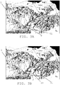
- the control unit 30 detects the movement of it, step 38. It then investigates if the pointer P is in the vicinity of the first object 01. This may be done through comparing the position of the pointer P with the position of the object 01. It can also be the comparison of the position of the pointer P with an area, like a rectangle, square, circle or ellipse surrounding the object 01. The tool P may then be found to be in the vicinity of the object 01, if the pointer P has the same position as the object O1 or is within the area surrounding the object 01. The situation that the pointer is in the vicinity of the object 01, is schematically shown in fig. 3A .
- control unit 30 receives input signals via a mouse or other user input unit indicating a selection of the object O1 shown in the overview picture.
- the control unit 30 can therefore be considered to comprise means for receiving input signals indicating a selection of an object of interest shown in the overview picture.
- step 40 the control unit 30 determines that the object is selected, step 41. This is then followed by the control unit 30 displaying a graphical symbol indicating the presence of the further information. In this embodiment the control unit 30 displays a further information icon I1 associated with the object on the display unit, step 42. However, if the pointer is not in the vicinity of the object, step 40, the movement is again detected, step 38. This means that if the position of the pointer P is the same as the position of the object O1 or inside the area surrounding the object 01, then the control unit 30 makes sure that the further information icon I1 is presented. The presenting of the icon I1 is shown in fig. 3B .
- This icon I1 is thus presented merely through the movement of the pointer P and without the object O1 having to be manipulated, for instance selected or clicked on. It is sufficient that the pointer P hovers above the icon 01.For this reason the control unit 30 can also be considered to comprise means for displaying a graphical symbol indicating the presence of the further information if the object is selected.
- This icon I1 provides an easily seen indicator to the operator that there exists further information about the object.
- the size of this indicator is furthermore small and therefore only occupies a small part of the screen and thus only provides a marginal disturbance of the overview.
- a detailed information view which may be made possible through the operator moving the pointer P to the icon I1 and selecting this icon, which is schematically shown in fig. 3C .
- a selection of the icon can be made in the same way through the operator merely moving the tool P over an area covered by this icon. This is the case in the first embodiment.
- a selection of the icon can also be made through keeping the pointer P above the object O1 also after the icon I1 is shown. It is also possible to require some more active participation of the operator such as a clicking on the icon.
- the control unit of the work station in this way detects if the icon is selected or not, step 44, and if it is selected the detailed information view is displayed.
- the detailed information view is displayed through displaying a further information window W1, step 46.
- the icon is not selected, step 44, the movement of the tool P is again investigated, step 38. If the pointer is moved away from the icon and object 01, these will furthermore disappear.
- the presenting of the further information window W1 is schematically shown in fig. 3D .
- the window is shown over a part of the overview picture.
- the control unit can also be considered to comprise means for displaying, on the display unit, a detailed information view W1 for the object O1 at least partly overlapping the overview picture 1, which is furthermore done based on the reception of the input signals from the user input unit. Since this detailed information view in this first embodiment is only displayed if both object and icon are selected, it is clear that the means for displaying the detailed information view is configured to only display this detailed information view if input signals are received indicating a selection of the icon.
- fig. 3D shows a first piece of overview data OD.
- This data can be context data relating to the object like weather information.
- process measurement data PM such as process data measured at the process control device or process control element, like power, voltage and current data.
- This data can be data from a variety of data sources inside the control system and outside the control system.
- the data includes statistical data Stat, like sizes and dates of power flows, and further activities data FuAc like following actions such as switching operations, alarm acknowledgement, etc.
- the control unit may thus receive input commands related to a certain action in the technical process, such as tripping a circuit breaker, and then that action is effectuated. It is of course also possible to display alarm data.
- the window includes small sized displays of further «navigatable» pictures, i.e. a set of miniaturized selectable overview pictures, which pictures are different from the overview picture currently displayed. These may here be selected and then the overview picture switched according to the selection.
- a single line diagram of the station, an alarm list and a circuit diagram of an element in the station All these various elements and diagrams can be selected in the detailed information view and then it is possible that the overview picture is replaced by a screen with the selected data or view.
- the control unit can also be considered to include means for receiving input signals indicating a selection of a miniaturized overview picture and means for displaying the selected overview picture as a new overview picture.
- the window W1 may here furthermore be customized to the operator, for instance include measurements, alarms and small sized views of favorite items of the operator. It may also be customized to the object type, so that all objects of the same type, for instance all substations, have the same type of additional information. It is also possible to adapt the content independently for an object.
- the presenting and selection of data can therefore be configured by the operator, perhaps subject to access rights to the information. This configuration can be made separately for each object as well as according to each object per object type and adapted according to power system state. This means that the occurrence of an alarm may determine what information should be provided in the window. Normally though the additional information window is always available to an operator, i.e. it can always be selected independently of the system state.
- the content of the window may be depending on the system state. It is furthermore possible that the window can be "pinned" or provided as a permanent window on to the screen.
- the exemplifying widow is an opaque window. However, it is also possible that it is made transparent or half way transparent in order to allow the overview picture to be visible behind it.
- the further information icon need not be displayed. It may be possible to directly select the detailed information view from the object in the overview picture.
- the invention eliminates the need of showing all the pages or views that contain information, including but not limited to real-time information, which the operator wants to view in addition to the overview picture. This is furthermore done in a simple way without the operator having to be distracted or perform other activities or switch to other pictures. This is furthermore also done without clogging the overview picture with a lot of additional information.
- the operator terminal may, as was previously described, preferably be provided in the form of one or more processors together with computer program memory including computer program code for performing the present invention.
- This computer program code may also be provided on one or more data carriers which performs the functionality of the present invention when the program code thereon is being loaded in an operator terminal.
- the invention may therefore also be provided as a computer program product loadable into a computer of the supervisory control system, comprising software code portions for carrying out the method according to the invention. It may also be provided as a computer program product stored on a computer readable storage medium, comprising computer readable program code means for causing a computer of a supervisory control system, to carry out the method of the invention.
- a computer readable storage medium in the for of CD ROM disk 50 carrying such a computer program product in the form of computer program code 48 or software code portions is schematically shown in fig. 5 .
Landscapes
- Engineering & Computer Science (AREA)
- Human Computer Interaction (AREA)
- Physics & Mathematics (AREA)
- General Physics & Mathematics (AREA)
- Automation & Control Theory (AREA)
- User Interface Of Digital Computer (AREA)
- Remote Monitoring And Control Of Power-Distribution Networks (AREA)
- Testing And Monitoring For Control Systems (AREA)
Description
- The present invention generally relates to display units in supervisory control systems provided for technical processes. More particularly the present invention relates to a method for enabling supervision of a technical system, a supervisory control system and computer program products that allow an operator to get an improved process control overview on a display unit also when there is a need for finding additional information.
- Operators have the need to view information relating to an element in a supervisory control system for controlling a technical process such as the process of electrical power transmission. The information can include process control data values that are provided by process interface units to a process control system, where the supervisory control system visualizes the process control information in different views and windows. The process control system can be a SCADA (Supervisory Control And Data Acquisition) system and in particular a power grid control system. Such information can be presented in overview pictures.
- However an operator of the supervisory control system may need to also see further information in relation to the technical process while still observing such an overview picture.
- Normally power grid or other SCADA systems operators have to search for such further information in multiple "pages" or views of the process control system. Such windows are then often related to a certain aspect of an object. An operator may therefore need to open several such windows or scenes, even though only a limited amount of further information may actually be of interest.
- It is thus possible that the operator has to keep many pages or views open, which in some cases may be displayed on multiple screens or display devices, in order to see just a few interesting pieces of information in each such view. This may make it hard for the operator to have an overview of the information being presented in the ordinary overview picture he or she is monitoring. Even if the number of additional windows being opened is small, the opening up of new views may distract the operator.
-
EP 1 331 536 - Document
US 2008/0141166 A1 relates to a graphical user interface for visualizing and controlling a computer network, wherein context-sensitive help relating to elements of the graphical representation may be immediately available, responsively to a selection device. - In view of what has been described above there exist different solutions for visualizing information for an operator of a supervisory control system. However, there is in this regard room for improvement, especially with regard to providing additional information while retaining the overview of a picture being presented.
- The present invention addresses this situation. The invention is therefore directed towards solving the problem of improving user friendliness in relation to presentation of an overview picture on a display unit in a supervisory control system.
- Accordingly, the present invention is based on the realization that there is a need for a better visualization of process control information when displaying an overview picture.
- The present invention is therefore directed towards solving the problem of providing a better and more user-friendly visualization of process control information when an overview picture is displayed.
- This problem is according to a first aspect of the invention solved through a supervisory control system for supervising a technical system, the supervisory control system comprising a display unit for displaying an overview picture of said technical system or part of said technical system, said overview picture comprising at least one object, wherein the supervisory control system further comprises a display view displaying the overview picture together with a detailed information view at least partly overlapping the overview picture, the detailed information view being associated with the object and comprising detailed information of the object.
- This problem is according to a second aspect of the invention solved through a method for enabling supervision of a technical system, said method being implemented in a supervisory control system comprising a display unit showing an overview picture of the technical system, the method comprising the steps of: receiving input signals indicating a selection of at least one object of interest shown in said overview picture, and
displaying, in response to receiving the input signals, a detailed information view at least partly overlapping the overview picture, the detailed information view being associated with the object and comprising detailed information of the object, whereby supervision of the technical system is enabled. - This problem is according to a third aspect of the invention solved through computer program products implementing the method.
- The invention eliminates the need of showing all the pages or views that contain information, including but not limited to real-time information, which the operator wants to view in addition to the overview picture. This is furthermore done in a simple way without the operator having to be distracted or perform other activities or switch to other pictures. This is furthermore also done without clogging the overview picture with a lot of additional information.
- The present invention will in the following be described with reference being made to the accompanying drawings, where
-
Fig. 1 schematically shows a computerized supervisory system for a technical process, -
Fig. 2 schematically shows an operator terminal of the supervisory system, -
Fig. 3A schematically shows a geographical overview picture of a power transmission system including a number of process control entities in the form of substations together with a pointing and selection tool and a graphical object representing a process control entity in the form of a substation, -
Fig. 3B schematically shows the geographical overview picture of the power transmission system with the pointing and selection tool, graphical substation symbol as well as a graphical symbol in the form of a further information icon associated with the substation object, -
Fig. 3C schematically shows the geographical overview picture of the power transmission system and object as the further information icon is selected using the pointing and selection tool, -
Fig. 3D schematically shows a further information window associated with the object and further information icon together with the geographical overview picture, -
Fig. 4 schematically shows a flow chart of a number of method steps being performed in a method according to the invention, and -
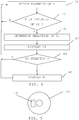
Fig. 5 schematically shows a computer program storage means comprising a computer program product providing the functionality of the method according to the invention. - In the following, embodiments of the invention providing the above described functionality will be described.
-
Fig. 1 schematically shows an exemplifying computerized supervisory control system orprocess control system 10. Theprocess control system 10 may typically be an object based computerized system for controlling a technical process or perhaps part of a technical process. Typical technical processes are for example electrical power generation, transmission and/or distribution processes, water purification and/or distribution processes, oil and/or gas production and distribution processes, petrochemical, chemical, pharmaceutical and food processing processes, as well as pulp and paper production processes. These are just some examples of technical processes where the supervisory control system orprocess control system 10 can be applied. There exist countless other technical processes. One preferred field where the present invention is to be applied is a power transmission system. Therefore the invention will in the following be described in relation to such a process. The technical process may be monitored by a user or operator through an operator terminal, which communicates with a control server handling monitoring and control of the technical process. - In
fig. 1 theprocess control system 10 therefore includes a number of operator andengineering terminals first server 16 providing control of the process, asecond server 17 providing monitoring of the process and adatabase 18 where data relating to control and possibly monitoring of the process is stored. Such data is here also called process control data. To the second bus there are furthermore connected process interface units for providing control and measurements in thesystem 10. Thefirst server 16 is therefore a part of a control system, while thesecond server 17 is a part of a monitoring system. In thefigure 1 , there are provided four suchprocess interface units power line 28. It should here be realized that some of these may only be provided for control, some only for measurements and some for both control and measurements. Such process interface units are thus involved in controlling the electrical power transmission process or measuring properties of the controlled process as well as properties or status of control and measurement units. Process interface units can include elements directed towards measuring quantities such as current, voltage and power. These elements can be current transformers and voltage transformers. The process interface units can also or instead include elements directed towards control operations like circuit breakers, relays, power semiconductor switches and tap changers. These are just a few of several different possible types of elements that can be provided in process interface units. A processes interface unit can furthermore be a part of a process interface device, which means that a process interface device is provided on one hierarchical level, while a process interface unit is provided on another, lower hierarchical level. - The
first server 16 here receives measurements of the process via the process interface units and controls the process via the process interface units based on these measurements. It also stores historical process control data in thedata base 18. Thesecond server 17 receives measurements via the process interface units as well as status data concerning the operation of process interface units and can generate alarm and event data that may be presented via theoperator terminals database 18. - In the example of
figure 1 , a so called Network Manager system runs on theprocess control system 10, which belongs to the group of SCADA (Supervisory Control And Data Acquisition) systems. The Network Manager system is particularly intended for the supervision and control of power transmission systems or gas systems. - An
operator terminal process control system 10 provide each a user interface to the Network Manager system. In the following, the details of such an operator terminal are explained based on the example ofoperator terminal 12, shown infigure 2 . Theoperator terminal 12 includes auser input unit 32, adisplay unit 34, acontrol unit 30 and aninterface 36 for communicating with thesystem 10 via the first bus B1. As mentioned above, the operator terminal provides a graphical user interface for an operator of theprocess control system 10. Thecontrol unit 30 may be a processor with an associated program memory including program code for performing the functionality of the present invention. This functionality will be described later on. Theuser input unit 32 is a unit through which a user of theoperator terminal 12 may enter data. As such it may be a keyboard, a keypad or a pointing and selection tool like a mouse. A combination of these may be also be used. It may also be combined with thedisplay unit 34 in order to form a touch screen. Theoperator terminal 12 may also include other user interfaces such as a speaker or a microphone in order to present and receive data to and from one or more users of the operator terminal in other ways than through the display and keyboard. An operator terminal in a process control system is only one example of a computer in which the present invention may be realized. - Process control data values from the various process interface units can be collected and stored in the
history data base 18 by thefirst server 16 as well as presented in real-time to an operator via theoperator terminal display 34. - An operator terminal of the supervisory system shows process control elements and process control devices involved in the control of the technical process. These elements and devices are then often shown in a number of different windows, where a window may be provided for one hierarchical system level. It is furthermore possible with other types of windows, like windows depicting data according to data type. It is for instance possible to display the general outline of the system on a geographical overview picture, which picture may show power lines connected to substations. This is a system view at a first hierarchical level. Such an overview picture is schematically shown in
fig. 3A - E . However, a system normally includes further system views at other hierarchical levels, for instance at lower system levels. It is as an example possible to show the internal structure of a substation, for instance in a single line diagram, as well as the structure of an element on a lower hierarchical level, such as a transformer, converter or some other element in a substation in an overview picture. In all these views it is at the same time possible to also display data of the functioning of the elements and devices in question, such as power being transmitted via a power line, voltage levels and current levels. It is also possible to show event and status data such as alarms. Alarms may also be displayed in a separate view in an alarm list. - With all this information that can be shown in various windows on an operator terminal, an operator may need to open up a number of windows in parallel for obtaining information in relation to an object such as a substation. This may lead to an "overflow" of information, where it is impossible to discern important information from less important and above all to get a clear grasp of to which object in an overview picture such data is linked.
- The present invention is provided for resolving this and other related problems.
- One embodiment of the invention will therefore now be described with reference being made to
fig. 3 A-D , where a number of display views presented on the work station are shown, and tofig. 4 , which shows a flow chart of a number of method step being performed in the method according to the first embodiment of the present invention. - On the
display unit 34 of thework station 12 there is shown anoverview picture 1 of the technical process or a part of the technical process, which overview picture here shows a number of interconnected substations, which substations are interconnected with power lines. These are presented as a number of graphical objects on a geographical map, which objects thus represent a process control entity, i.e. an entity involved in the control of the process. In this embodiment the process control entity is furthermore a process control device. It is according to the invention possible to obtain further information about these objects. - This overview picture is just one type of overview picture with which the present invention can be used. It is for instance also possible to use the present invention in overview pictures on elements further down in the hierarchy, such as an overview picture of a substation or an overview picture of an element in a substation like a transformer. It is also possible to show overview pictures at higher levels. The overview picture need furthermore not be geographical but can be a logical overview picture such as an overview of the electrical interconnection of elements, like a single line diagram.
- As is known in these types of systems the work station also provides a pointing and selection tool for the operator, such as a cursor or pointer, in which various locations of the
overview picture 1 can be selected or marked. Infig. 3A - D this pointer P is shown as an arrow. The work station can therefore detect the positions of the pointer P on thedisplay unit 34 and determine what objects are provided close to such positions. It is also possible to select an object with this pointer, for instance in combination with actuating a user input unit, such as clicking using a mouse or track ball or with a tapping on a touch screen. This means that through moving the tool P on thedisplay unit 34 using a user input unit, thecontrol unit 30 of the work station will receive input signals related to selections made by the operator. - In the following the method will furthermore be described in relation to one such object on the overview picture. In this example the object O1 is a graphical object representing a power control device that is a substation and here a substation named "Mapleton". It should be realized that the method steps described below can be applied on other objects in the overview picture, like objects representing other substations or power lines. The method may be possible to perform in relation to all objects in an overview picture. However, it is also possible that it is limited to only some types of objects, for instance objects representing process interface devices or process interface units or objects representing other types of elements, such as elements used for transfer of power. It is for instance possible that the method steps to be described are only performed in relation to substations, but are not possible to perform in relation to other objects such as power lines. The method can also be performed on objects in lower hierarchical levels. It is for instance possible to perform the method steps for an object in an overview picture of a substation, for instance single line diagram, where an object may then for instance be a process interface unit comprising an element such as a transformer.
- As the operator thus moves the pointer P on the
screen 34 across theoverview picture 1, thecontrol unit 30 detects the movement of it,step 38. It then investigates if the pointer P is in the vicinity of thefirst object 01. This may be done through comparing the position of the pointer P with the position of theobject 01. It can also be the comparison of the position of the pointer P with an area, like a rectangle, square, circle or ellipse surrounding theobject 01. The tool P may then be found to be in the vicinity of theobject 01, if the pointer P has the same position as the object O1 or is within the area surrounding theobject 01. The situation that the pointer is in the vicinity of theobject 01, is schematically shown infig. 3A . It is therefore clear that movement of the pointer P to the vicinity of the object O1 means that thecontrol unit 30 receives input signals via a mouse or other user input unit indicating a selection of the object O1 shown in the overview picture. Thecontrol unit 30 can therefore be considered to comprise means for receiving input signals indicating a selection of an object of interest shown in the overview picture. - If then the pointer P is found to have a position in the vicinity of the object,
step 40, thecontrol unit 30 determines that the object is selected,step 41. This is then followed by thecontrol unit 30 displaying a graphical symbol indicating the presence of the further information. In this embodiment thecontrol unit 30 displays a further information icon I1 associated with the object on the display unit,step 42. However, if the pointer is not in the vicinity of the object,step 40, the movement is again detected,step 38. This means that if the position of the pointer P is the same as the position of the object O1 or inside the area surrounding theobject 01, then thecontrol unit 30 makes sure that the further information icon I1 is presented. The presenting of the icon I1 is shown infig. 3B . This icon I1 is thus presented merely through the movement of the pointer P and without the object O1 having to be manipulated, for instance selected or clicked on. It is sufficient that the pointer P hovers above the icon 01.For this reason thecontrol unit 30 can also be considered to comprise means for displaying a graphical symbol indicating the presence of the further information if the object is selected. - In this way it is possible for the operator to see that there is further information in relation to an object without having the overview cluttered with a lot of further information and without blocking the overview picture with other windows and screens. This icon I1 provides an easily seen indicator to the operator that there exists further information about the object. The size of this indicator is furthermore small and therefore only occupies a small part of the screen and thus only provides a marginal disturbance of the overview.
- It is then possible for the operator to see at least some of this further information in a detailed information view, which may be made possible through the operator moving the pointer P to the icon I1 and selecting this icon, which is schematically shown in
fig. 3C . A selection of the icon can be made in the same way through the operator merely moving the tool P over an area covered by this icon. This is the case in the first embodiment. A selection of the icon can also be made through keeping the pointer P above the object O1 also after the icon I1 is shown. It is also possible to require some more active participation of the operator such as a clicking on the icon. The control unit of the work station in this way detects if the icon is selected or not, step 44, and if it is selected the detailed information view is displayed. In this embodiment, the detailed information view is displayed through displaying a further information window W1,step 46. However if the icon is not selected,step 44, the movement of the tool P is again investigated,step 38. If the pointer is moved away from the icon andobject 01, these will furthermore disappear. - The presenting of the further information window W1 is schematically shown in
fig. 3D . As can be seen here the window is shown over a part of the overview picture. However, the window W1 is fairly small, why the overview is still good. For this reason the control unit can also be considered to comprise means for displaying, on the display unit, a detailed information view W1 for the object O1 at least partly overlapping theoverview picture 1, which is furthermore done based on the reception of the input signals from the user input unit. Since this detailed information view in this first embodiment is only displayed if both object and icon are selected, it is clear that the means for displaying the detailed information view is configured to only display this detailed information view if input signals are received indicating a selection of the icon. - In this way the overview picture is thus retained while the additional information is presented.
- In the window W1 it may be possible to present a number of pieces of additional information such as information about what content is linked to the object. This additional information may be information originally appearing in several different other overview pictures. As an example
fig. 3D shows a first piece of overview data OD. This data can be context data relating to the object like weather information. It is also possible that there is process measurement data PM, such as process data measured at the process control device or process control element, like power, voltage and current data. This data can be data from a variety of data sources inside the control system and outside the control system. It is also possible that the data includes statistical data Stat, like sizes and dates of power flows, and further activities data FuAc like following actions such as switching operations, alarm acknowledgement, etc. The control unit may thus receive input commands related to a certain action in the technical process, such as tripping a circuit breaker, and then that action is effectuated. It is of course also possible to display alarm data. - It is here also possible that the window includes small sized displays of further «navigatable» pictures, i.e. a set of miniaturized selectable overview pictures, which pictures are different from the overview picture currently displayed. These may here be selected and then the overview picture switched according to the selection. As an example there is here shown a single line diagram of the station, an alarm list and a circuit diagram of an element in the station. All these various elements and diagrams can be selected in the detailed information view and then it is possible that the overview picture is replaced by a screen with the selected data or view. This means that the control unit can also be considered to include means for receiving input signals indicating a selection of a miniaturized overview picture and means for displaying the selected overview picture as a new overview picture.
- The window W1 may here furthermore be customized to the operator, for instance include measurements, alarms and small sized views of favorite items of the operator. It may also be customized to the object type, so that all objects of the same type, for instance all substations, have the same type of additional information. It is also possible to adapt the content independently for an object. The presenting and selection of data can therefore be configured by the operator, perhaps subject to access rights to the information. This configuration can be made separately for each object as well as according to each object per object type and adapted according to power system state. This means that the occurrence of an alarm may determine what information should be provided in the window. Normally though the additional information window is always available to an operator, i.e. it can always be selected independently of the system state. However, the content of the window may be depending on the system state. It is furthermore possible that the window can be "pinned" or provided as a permanent window on to the screen. The exemplifying widow is an opaque window. However, it is also possible that it is made transparent or half way transparent in order to allow the overview picture to be visible behind it.
- It should also be realized that the further information icon need not be displayed. It may be possible to directly select the detailed information view from the object in the overview picture.
- The invention eliminates the need of showing all the pages or views that contain information, including but not limited to real-time information, which the operator wants to view in addition to the overview picture. This is furthermore done in a simple way without the operator having to be distracted or perform other activities or switch to other pictures. This is furthermore also done without clogging the overview picture with a lot of additional information.
- The operator terminal may, as was previously described, preferably be provided in the form of one or more processors together with computer program memory including computer program code for performing the present invention. This computer program code may also be provided on one or more data carriers which performs the functionality of the present invention when the program code thereon is being loaded in an operator terminal.
- The invention may therefore also be provided as a computer program product loadable into a computer of the supervisory control system, comprising software code portions for carrying out the method according to the invention. It may also be provided as a computer program product stored on a computer readable storage medium, comprising computer readable program code means for causing a computer of a supervisory control system, to carry out the method of the invention. Such a computer readable storage medium in the for of
CD ROM disk 50 carrying such a computer program product in the form ofcomputer program code 48 or software code portions is schematically shown infig. 5 .
Claims (15)
- A supervisory control system (10) for supervising a technical system, said supervisory control system (10) comprising a display unit (34) for displaying an overview picture (1) of said technical system or part of said technical system, said overview picture (1) comprising at least one object (O1) representing an entity of the technical system, said supervisory control system (10) further comprising- a display view displaying said overview picture (1) together with a detailed information view (W1) at least partly overlapping said overview picture, said detailed information view being associated with the object and comprising detailed information about the entity represented by the object,- means for receiving input signals indicating a selection of the object (O1) shown in said overview picture (1)- means for displaying a graphical symbol indicating the presence of said further information if the object is selected, and- means for displaying, on said display unit, said detailed information view (W1) only if input signals are received indicating a selection of said graphical symbol.
- The supervisory control system (10) as claimed in claim 1, wherein said input signals include position data of a pointing and selection tool (P) of the display unit and further comprising means for determining that the object is selected if the position of the pointing and selection tool is in the vicinity of the position of the object.
- The supervisory control system according to claim 2, wherein the object is determined to be selected without further actuation of a user input unit.
- The supervisory control system according to one of claims 1 to 3, wherein the overview picture is a geographical overview picture of a power transmission system.
- The supervisory control system according to one of claims 1 to 3, further comprising means for displaying said detailed information view (W1) in an opaque or transparent manner over said overview picture (1).
- The supervisory control system according to one of claims 1 to 3, further comprising means for receiving, in said detailed information view, input commands related to a certain action in the technical process, such as tripping a circuit breaker, and effectuating said action.
- The supervisory control system according to one of claims 1 to 3, wherein said detailed information view comprises a set of other miniaturized selectable overview pictures.
- The supervisory control system according to claim 7, further comprising means for receiving input signals indicating a selection of a miniaturized overview picture and means for displaying the selected overview picture as a new overview picture.
- A method for enabling supervision of a technical system, said method being implemented in a supervisory control system (10) comprising a display unit (34) showing an overview picture (1) of said technical system, characterized by the steps of:- receiving (38, 40) input signals indicating a selection of at least one object (O1) of interest shown in said overview picture (1),- displaying (42) a graphical symbol (II) indicating a presence of further information about an entity of the technical system represented by the object, if the object is selected,- receiving input signals indicating a selection of said graphical symbol, and- displaying (46), in response to receiving said input signals, a detailed information view (W1) at least partly overlapping said overview picture, said detailed information view comprising said further information, whereby supervision of said technical system is enabled.
- The method as claimed in claim 9, wherein said input signals include position data of a pointing and selection tool (P) of the display unit and further comprising the step of determining (41) that the object is selected if (40) the position of the pointing and selection tool is in the vicinity of the position of the object.
- The method according to claim 10, further comprising the step of determining that the object is selected without actuating a user input unit.
- The method as claimed in any of claims 9 to 11, further comprising the steps of receiving, in said detailed information view (W1), input commands related to a certain action, such as tripping a circuit breaker, and effectuating said action.
- The method as claimed in any of claims 9 to 11, comprising the further step of displaying said detailed information view (W1) in an opaque or transparent manner over said overview picture (1).
- The method as claimed in any of claims 9 to 11, wherein said detailed information view comprises a set of other miniaturized selectable overview pictures, comprising the further steps of receiving input signals indicating a selection of a miniaturized overview picture and displaying the selected overview picture as a new overview picture.
- A computer program product (48) stored on a computer readable storage medium (50) and loadable into a computer (12) of a supervisory control system (10), comprising software code portions for carrying out the method as claimed in any of claims 9 - 14 when said product is run on said computer (12).
Applications Claiming Priority (2)
| Application Number | Priority Date | Filing Date | Title |
|---|---|---|---|
| US20294109P | 2009-04-22 | 2009-04-22 | |
| PCT/EP2010/055214 WO2010122032A1 (en) | 2009-04-22 | 2010-04-20 | Improved process control overview on a supervisory control system display unit |
Publications (2)
| Publication Number | Publication Date |
|---|---|
| EP2422253A1 EP2422253A1 (en) | 2012-02-29 |
| EP2422253B1 true EP2422253B1 (en) | 2020-11-04 |
Family
ID=41074442
Family Applications (2)
| Application Number | Title | Priority Date | Filing Date |
|---|---|---|---|
| EP09780319.1A Active EP2422252B1 (en) | 2009-04-22 | 2009-07-08 | Supervisory control system, method and computer program products |
| EP10716810.6A Active EP2422253B1 (en) | 2009-04-22 | 2010-04-20 | Improved process control overview on a supervisory control system display unit |
Family Applications Before (1)
| Application Number | Title | Priority Date | Filing Date |
|---|---|---|---|
| EP09780319.1A Active EP2422252B1 (en) | 2009-04-22 | 2009-07-08 | Supervisory control system, method and computer program products |
Country Status (4)
| Country | Link |
|---|---|
| US (2) | US8872857B2 (en) |
| EP (2) | EP2422252B1 (en) |
| CN (2) | CN102414634B (en) |
| WO (2) | WO2010121672A1 (en) |
Families Citing this family (9)
| Publication number | Priority date | Publication date | Assignee | Title |
|---|---|---|---|---|
| EP2418554A1 (en) * | 2010-08-02 | 2012-02-15 | ABB Research Ltd. | Method and computer program products for enabling supervision and control of a technical system |
| EP2656155B1 (en) * | 2010-12-22 | 2015-07-29 | ABB Research Ltd. | Method and system for monitoring an industrial system involving an eye tracking system |
| CN104054032B (en) * | 2012-02-23 | 2016-09-07 | Abb研究有限公司 | For the method providing the navigational tool of user interface for industrial control system |
| DE102012208457A1 (en) * | 2012-05-21 | 2013-11-21 | Siemens Aktiengesellschaft | Display and operating device for a control room |
| CN102779155A (en) * | 2012-05-31 | 2012-11-14 | 新奥特(北京)视频技术有限公司 | Method for quickly positioning broadcasting information |
| US9240164B2 (en) * | 2013-02-27 | 2016-01-19 | Honeywell International Inc. | Apparatus and method for providing a pan and zoom display for a representation of a process system |
| WO2015106834A1 (en) | 2014-01-16 | 2015-07-23 | Abb Technology Ag | Method and arrangement for visualizing an alarm of an automation or control system in a geographic information system |
| KR102706927B1 (en) * | 2021-07-13 | 2024-09-13 | 주식회사 썬에이치에스티 | A platform that supports error history lists and alarm services, and a system that supports them |
| US20240312082A1 (en) * | 2023-03-14 | 2024-09-19 | Arka Energy Inc. | System and method for generating single-line diagrams and three-line diagrams |
Citations (1)
| Publication number | Priority date | Publication date | Assignee | Title |
|---|---|---|---|---|
| US20080141166A1 (en) * | 2006-12-11 | 2008-06-12 | Cisco Technology, Inc. | Using images in alternative navigation |
Family Cites Families (14)
| Publication number | Priority date | Publication date | Assignee | Title |
|---|---|---|---|---|
| AU745009B2 (en) * | 1997-12-01 | 2002-03-07 | Rovi Guides, Inc. | Electronic program guide system with advertising messages in pop-ups |
| JP2001008384A (en) * | 1999-06-21 | 2001-01-12 | Toshiba Corp | System screen display device and recording medium |
| JP3848920B2 (en) | 2000-10-20 | 2006-11-22 | ダイセル化学工業株式会社 | Plant control monitoring device |
| US7672104B2 (en) * | 2002-05-06 | 2010-03-02 | Cyber Switching, Inc. | Current protection apparatus and method |
| US8117542B2 (en) * | 2004-08-16 | 2012-02-14 | Microsoft Corporation | User interface for displaying selectable software functionality controls that are contextually relevant to a selected object |
| US7479970B2 (en) * | 2005-01-12 | 2009-01-20 | Microsoft Corporation | Systems and methods that facilitate process monitoring, navigation, and parameter-based magnification |
| US8125310B2 (en) * | 2005-04-01 | 2012-02-28 | Abb Research Ltd. | Method and system for providing a user interface |
| WO2007050175A2 (en) | 2005-10-24 | 2007-05-03 | The Toro Company | Computer-operated landscape irrigation and lighting system |
| WO2007093850A2 (en) * | 2005-12-15 | 2007-08-23 | Abb Technology Ltd. | Method and apparatus for multiple control screens |
| US8849980B2 (en) | 2006-02-06 | 2014-09-30 | International Business Machines Corporation | Apparatus, system, and method for monitoring computer system components |
| US20070216712A1 (en) * | 2006-03-20 | 2007-09-20 | John Louch | Image transformation based on underlying data |
| EP1965301A1 (en) | 2007-02-27 | 2008-09-03 | Abb Research Ltd. | Method and system for generating a control system user interface |
| JP4758950B2 (en) * | 2007-06-07 | 2011-08-31 | 株式会社日立製作所 | PLANT MONITORING DEVICE AND PLANT OPERATION MONITORING METHOD |
| US20090210277A1 (en) * | 2008-02-14 | 2009-08-20 | Hardin H Wesley | System and method for managing a geographically-expansive construction project |
-
2009
- 2009-07-08 US US13/265,673 patent/US8872857B2/en active Active
- 2009-07-08 CN CN200980158809.4A patent/CN102414634B/en active Active
- 2009-07-08 WO PCT/EP2009/058672 patent/WO2010121672A1/en not_active Ceased
- 2009-07-08 EP EP09780319.1A patent/EP2422252B1/en active Active
-
2010
- 2010-04-20 EP EP10716810.6A patent/EP2422253B1/en active Active
- 2010-04-20 WO PCT/EP2010/055214 patent/WO2010122032A1/en not_active Ceased
- 2010-04-20 CN CN2010800288269A patent/CN102460328A/en active Pending
-
2011
- 2011-10-24 US US13/280,063 patent/US20120116542A1/en not_active Abandoned
Patent Citations (1)
| Publication number | Priority date | Publication date | Assignee | Title |
|---|---|---|---|---|
| US20080141166A1 (en) * | 2006-12-11 | 2008-06-12 | Cisco Technology, Inc. | Using images in alternative navigation |
Also Published As
| Publication number | Publication date |
|---|---|
| CN102414634B (en) | 2014-01-01 |
| WO2010122032A1 (en) | 2010-10-28 |
| US20120032985A1 (en) | 2012-02-09 |
| EP2422252A1 (en) | 2012-02-29 |
| WO2010121672A1 (en) | 2010-10-28 |
| CN102460328A (en) | 2012-05-16 |
| EP2422253A1 (en) | 2012-02-29 |
| US8872857B2 (en) | 2014-10-28 |
| CN102414634A (en) | 2012-04-11 |
| US20120116542A1 (en) | 2012-05-10 |
| EP2422252B1 (en) | 2019-10-09 |
Similar Documents
| Publication | Publication Date | Title |
|---|---|---|
| US20120116542A1 (en) | Process control overview on a supervisory control system display unit | |
| US9037273B2 (en) | Operator terminal in a process control system | |
| EP2817687B1 (en) | A navigation tool of a user interface for an industrial control system | |
| JP2022051805A (en) | Method and device for graphically displaying process control system information | |
| US9983575B2 (en) | Systems and methods to graphically display process control system information | |
| US20100131877A1 (en) | Building control system user interface with docking feature | |
| EP2380137B1 (en) | Method and device to supervise a power network | |
| WO2009117741A1 (en) | Decision support control centers | |
| JP2000287388A (en) | Graphic user interface | |
| EP2710435B1 (en) | System, method, work station and computer program product for controlling an industrial process | |
| US20130080959A1 (en) | Simplified navigation among process control views in a process control system | |
| KR101778102B1 (en) | Method for providing graphic user interface dedicated to power facility comprehensive preventive diagnosis and power facility comprehensive preventive diagnosis system | |
| EP4621513B1 (en) | Processing system and method for electric power system control and/or monitoring, and machine-readable instruction code | |
| JP2000287387A (en) | Graphic user interface | |
| EP2422251B1 (en) | Method for visualization of transmission flow in a system, an operator terminal and a supervisory control system | |
| JP4874213B2 (en) | Supervisory control system | |
| WO2015106834A1 (en) | Method and arrangement for visualizing an alarm of an automation or control system in a geographic information system | |
| WO2010121671A1 (en) | A method for displaying configuration and status of a plant | |
| WO2014008941A1 (en) | A method of handling an alarm or an event within a process control system | |
| JP2025044564A (en) | Monitoring device, monitoring method, and monitoring program | |
| WO2015106835A1 (en) | Method and arrangement for facilitating operation of an automation or control system | |
| WO2010121667A1 (en) | Improved overview of process control data on an operator terminal display of a process control system | |
| JP2017126108A (en) | Device management apparatus and method |
Legal Events
| Date | Code | Title | Description |
|---|---|---|---|
| PUAI | Public reference made under article 153(3) epc to a published international application that has entered the european phase |
Free format text: ORIGINAL CODE: 0009012 |
|
| 17P | Request for examination filed |
Effective date: 20111018 |
|
| AK | Designated contracting states |
Kind code of ref document: A1 Designated state(s): AT BE BG CH CY CZ DE DK EE ES FI FR GB GR HR HU IE IS IT LI LT LU LV MC MK MT NL NO PL PT RO SE SI SK SM TR |
|
| RIN1 | Information on inventor provided before grant (corrected) |
Inventor name: MIKKELSEN, CHRISTINE Inventor name: VETTER, CLAUS Inventor name: KOTA, DILIP |
|
| DAX | Request for extension of the european patent (deleted) | ||
| STAA | Information on the status of an ep patent application or granted ep patent |
Free format text: STATUS: EXAMINATION IS IN PROGRESS |
|
| 17Q | First examination report despatched |
Effective date: 20190502 |
|
| RAP1 | Party data changed (applicant data changed or rights of an application transferred) |
Owner name: ABB SCHWEIZ AG |
|
| GRAP | Despatch of communication of intention to grant a patent |
Free format text: ORIGINAL CODE: EPIDOSNIGR1 |
|
| STAA | Information on the status of an ep patent application or granted ep patent |
Free format text: STATUS: GRANT OF PATENT IS INTENDED |
|
| INTG | Intention to grant announced |
Effective date: 20200512 |
|
| RAP1 | Party data changed (applicant data changed or rights of an application transferred) |
Owner name: ABB POWER GRIDS SWITZERLAND AG |
|
| GRAS | Grant fee paid |
Free format text: ORIGINAL CODE: EPIDOSNIGR3 |
|
| GRAA | (expected) grant |
Free format text: ORIGINAL CODE: 0009210 |
|
| STAA | Information on the status of an ep patent application or granted ep patent |
Free format text: STATUS: THE PATENT HAS BEEN GRANTED |
|
| AK | Designated contracting states |
Kind code of ref document: B1 Designated state(s): AT BE BG CH CY CZ DE DK EE ES FI FR GB GR HR HU IE IS IT LI LT LU LV MC MK MT NL NO PL PT RO SE SI SK SM TR |
|
| REG | Reference to a national code |
Ref country code: GB Ref legal event code: FG4D |
|
| REG | Reference to a national code |
Ref country code: CH Ref legal event code: EP |
|
| REG | Reference to a national code |
Ref country code: AT Ref legal event code: REF Ref document number: 1331612 Country of ref document: AT Kind code of ref document: T Effective date: 20201115 |
|
| REG | Reference to a national code |
Ref country code: DE Ref legal event code: R096 Ref document number: 602010065827 Country of ref document: DE |
|
| REG | Reference to a national code |
Ref country code: IE Ref legal event code: FG4D |
|
| REG | Reference to a national code |
Ref country code: NL Ref legal event code: MP Effective date: 20201104 |
|
| REG | Reference to a national code |
Ref country code: AT Ref legal event code: MK05 Ref document number: 1331612 Country of ref document: AT Kind code of ref document: T Effective date: 20201104 |
|
| PG25 | Lapsed in a contracting state [announced via postgrant information from national office to epo] |
Ref country code: FI Free format text: LAPSE BECAUSE OF FAILURE TO SUBMIT A TRANSLATION OF THE DESCRIPTION OR TO PAY THE FEE WITHIN THE PRESCRIBED TIME-LIMIT Effective date: 20201104 Ref country code: NO Free format text: LAPSE BECAUSE OF FAILURE TO SUBMIT A TRANSLATION OF THE DESCRIPTION OR TO PAY THE FEE WITHIN THE PRESCRIBED TIME-LIMIT Effective date: 20210204 Ref country code: PT Free format text: LAPSE BECAUSE OF FAILURE TO SUBMIT A TRANSLATION OF THE DESCRIPTION OR TO PAY THE FEE WITHIN THE PRESCRIBED TIME-LIMIT Effective date: 20210304 Ref country code: GR Free format text: LAPSE BECAUSE OF FAILURE TO SUBMIT A TRANSLATION OF THE DESCRIPTION OR TO PAY THE FEE WITHIN THE PRESCRIBED TIME-LIMIT Effective date: 20210205 |
|
| PG25 | Lapsed in a contracting state [announced via postgrant information from national office to epo] |
Ref country code: IS Free format text: LAPSE BECAUSE OF FAILURE TO SUBMIT A TRANSLATION OF THE DESCRIPTION OR TO PAY THE FEE WITHIN THE PRESCRIBED TIME-LIMIT Effective date: 20210304 Ref country code: ES Free format text: LAPSE BECAUSE OF FAILURE TO SUBMIT A TRANSLATION OF THE DESCRIPTION OR TO PAY THE FEE WITHIN THE PRESCRIBED TIME-LIMIT Effective date: 20201104 Ref country code: AT Free format text: LAPSE BECAUSE OF FAILURE TO SUBMIT A TRANSLATION OF THE DESCRIPTION OR TO PAY THE FEE WITHIN THE PRESCRIBED TIME-LIMIT Effective date: 20201104 Ref country code: BG Free format text: LAPSE BECAUSE OF FAILURE TO SUBMIT A TRANSLATION OF THE DESCRIPTION OR TO PAY THE FEE WITHIN THE PRESCRIBED TIME-LIMIT Effective date: 20210204 Ref country code: SE Free format text: LAPSE BECAUSE OF FAILURE TO SUBMIT A TRANSLATION OF THE DESCRIPTION OR TO PAY THE FEE WITHIN THE PRESCRIBED TIME-LIMIT Effective date: 20201104 Ref country code: LV Free format text: LAPSE BECAUSE OF FAILURE TO SUBMIT A TRANSLATION OF THE DESCRIPTION OR TO PAY THE FEE WITHIN THE PRESCRIBED TIME-LIMIT Effective date: 20201104 Ref country code: PL Free format text: LAPSE BECAUSE OF FAILURE TO SUBMIT A TRANSLATION OF THE DESCRIPTION OR TO PAY THE FEE WITHIN THE PRESCRIBED TIME-LIMIT Effective date: 20201104 |
|
| REG | Reference to a national code |
Ref country code: LT Ref legal event code: MG9D |
|
| PG25 | Lapsed in a contracting state [announced via postgrant information from national office to epo] |
Ref country code: HR Free format text: LAPSE BECAUSE OF FAILURE TO SUBMIT A TRANSLATION OF THE DESCRIPTION OR TO PAY THE FEE WITHIN THE PRESCRIBED TIME-LIMIT Effective date: 20201104 |
|
| PG25 | Lapsed in a contracting state [announced via postgrant information from national office to epo] |
Ref country code: CZ Free format text: LAPSE BECAUSE OF FAILURE TO SUBMIT A TRANSLATION OF THE DESCRIPTION OR TO PAY THE FEE WITHIN THE PRESCRIBED TIME-LIMIT Effective date: 20201104 Ref country code: EE Free format text: LAPSE BECAUSE OF FAILURE TO SUBMIT A TRANSLATION OF THE DESCRIPTION OR TO PAY THE FEE WITHIN THE PRESCRIBED TIME-LIMIT Effective date: 20201104 Ref country code: SM Free format text: LAPSE BECAUSE OF FAILURE TO SUBMIT A TRANSLATION OF THE DESCRIPTION OR TO PAY THE FEE WITHIN THE PRESCRIBED TIME-LIMIT Effective date: 20201104 Ref country code: SK Free format text: LAPSE BECAUSE OF FAILURE TO SUBMIT A TRANSLATION OF THE DESCRIPTION OR TO PAY THE FEE WITHIN THE PRESCRIBED TIME-LIMIT Effective date: 20201104 Ref country code: RO Free format text: LAPSE BECAUSE OF FAILURE TO SUBMIT A TRANSLATION OF THE DESCRIPTION OR TO PAY THE FEE WITHIN THE PRESCRIBED TIME-LIMIT Effective date: 20201104 Ref country code: LT Free format text: LAPSE BECAUSE OF FAILURE TO SUBMIT A TRANSLATION OF THE DESCRIPTION OR TO PAY THE FEE WITHIN THE PRESCRIBED TIME-LIMIT Effective date: 20201104 |
|
| REG | Reference to a national code |
Ref country code: DE Ref legal event code: R097 Ref document number: 602010065827 Country of ref document: DE |
|
| PG25 | Lapsed in a contracting state [announced via postgrant information from national office to epo] |
Ref country code: DK Free format text: LAPSE BECAUSE OF FAILURE TO SUBMIT A TRANSLATION OF THE DESCRIPTION OR TO PAY THE FEE WITHIN THE PRESCRIBED TIME-LIMIT Effective date: 20201104 |
|
| PLBE | No opposition filed within time limit |
Free format text: ORIGINAL CODE: 0009261 |
|
| STAA | Information on the status of an ep patent application or granted ep patent |
Free format text: STATUS: NO OPPOSITION FILED WITHIN TIME LIMIT |
|
| 26N | No opposition filed |
Effective date: 20210805 |
|
| PG25 | Lapsed in a contracting state [announced via postgrant information from national office to epo] |
Ref country code: IT Free format text: LAPSE BECAUSE OF FAILURE TO SUBMIT A TRANSLATION OF THE DESCRIPTION OR TO PAY THE FEE WITHIN THE PRESCRIBED TIME-LIMIT Effective date: 20201104 Ref country code: NL Free format text: LAPSE BECAUSE OF FAILURE TO SUBMIT A TRANSLATION OF THE DESCRIPTION OR TO PAY THE FEE WITHIN THE PRESCRIBED TIME-LIMIT Effective date: 20201104 |
|
| PG25 | Lapsed in a contracting state [announced via postgrant information from national office to epo] |
Ref country code: SI Free format text: LAPSE BECAUSE OF FAILURE TO SUBMIT A TRANSLATION OF THE DESCRIPTION OR TO PAY THE FEE WITHIN THE PRESCRIBED TIME-LIMIT Effective date: 20201104 Ref country code: MC Free format text: LAPSE BECAUSE OF FAILURE TO SUBMIT A TRANSLATION OF THE DESCRIPTION OR TO PAY THE FEE WITHIN THE PRESCRIBED TIME-LIMIT Effective date: 20201104 |
|
| PG25 | Lapsed in a contracting state [announced via postgrant information from national office to epo] |
Ref country code: LU Free format text: LAPSE BECAUSE OF NON-PAYMENT OF DUE FEES Effective date: 20210420 |
|
| REG | Reference to a national code |
Ref country code: BE Ref legal event code: MM Effective date: 20210430 |
|
| PG25 | Lapsed in a contracting state [announced via postgrant information from national office to epo] |
Ref country code: CH Free format text: LAPSE BECAUSE OF NON-PAYMENT OF DUE FEES Effective date: 20210430 Ref country code: LI Free format text: LAPSE BECAUSE OF NON-PAYMENT OF DUE FEES Effective date: 20210430 |
|
| PG25 | Lapsed in a contracting state [announced via postgrant information from national office to epo] |
Ref country code: IE Free format text: LAPSE BECAUSE OF NON-PAYMENT OF DUE FEES Effective date: 20210420 |
|
| PG25 | Lapsed in a contracting state [announced via postgrant information from national office to epo] |
Ref country code: IS Free format text: LAPSE BECAUSE OF FAILURE TO SUBMIT A TRANSLATION OF THE DESCRIPTION OR TO PAY THE FEE WITHIN THE PRESCRIBED TIME-LIMIT Effective date: 20210304 |
|
| REG | Reference to a national code |
Ref country code: DE Ref legal event code: R081 Ref document number: 602010065827 Country of ref document: DE Owner name: HITACHI ENERGY SWITZERLAND AG, CH Free format text: FORMER OWNER: ABB POWER GRIDS SWITZERLAND AG, BADEN, CH Ref country code: DE Ref legal event code: R081 Ref document number: 602010065827 Country of ref document: DE Owner name: HITACHI ENERGY LTD, CH Free format text: FORMER OWNER: ABB POWER GRIDS SWITZERLAND AG, BADEN, CH |
|
| PG25 | Lapsed in a contracting state [announced via postgrant information from national office to epo] |
Ref country code: BE Free format text: LAPSE BECAUSE OF NON-PAYMENT OF DUE FEES Effective date: 20210430 |
|
| PG25 | Lapsed in a contracting state [announced via postgrant information from national office to epo] |
Ref country code: HU Free format text: LAPSE BECAUSE OF FAILURE TO SUBMIT A TRANSLATION OF THE DESCRIPTION OR TO PAY THE FEE WITHIN THE PRESCRIBED TIME-LIMIT; INVALID AB INITIO Effective date: 20100420 Ref country code: CY Free format text: LAPSE BECAUSE OF FAILURE TO SUBMIT A TRANSLATION OF THE DESCRIPTION OR TO PAY THE FEE WITHIN THE PRESCRIBED TIME-LIMIT Effective date: 20201104 |
|
| P01 | Opt-out of the competence of the unified patent court (upc) registered |
Effective date: 20230527 |
|
| REG | Reference to a national code |
Ref country code: DE Ref legal event code: R082 Ref document number: 602010065827 Country of ref document: DE Representative=s name: DENNEMEYER & ASSOCIATES RECHTSANWALTSGESELLSCH, DE Ref country code: DE Ref legal event code: R082 Ref document number: 602010065827 Country of ref document: DE Representative=s name: DENNEMEYER & ASSOCIATES S.A., DE Ref country code: DE Ref legal event code: R081 Ref document number: 602010065827 Country of ref document: DE Owner name: HITACHI ENERGY LTD, CH Free format text: FORMER OWNER: HITACHI ENERGY SWITZERLAND AG, BADEN, CH |
|
| PG25 | Lapsed in a contracting state [announced via postgrant information from national office to epo] |
Ref country code: MK Free format text: LAPSE BECAUSE OF FAILURE TO SUBMIT A TRANSLATION OF THE DESCRIPTION OR TO PAY THE FEE WITHIN THE PRESCRIBED TIME-LIMIT Effective date: 20201104 |
|
| REG | Reference to a national code |
Ref country code: GB Ref legal event code: 732E Free format text: REGISTERED BETWEEN 20240718 AND 20240724 |
|
| PG25 | Lapsed in a contracting state [announced via postgrant information from national office to epo] |
Ref country code: MT Free format text: LAPSE BECAUSE OF FAILURE TO SUBMIT A TRANSLATION OF THE DESCRIPTION OR TO PAY THE FEE WITHIN THE PRESCRIBED TIME-LIMIT Effective date: 20201104 |
|
| REG | Reference to a national code |
Ref country code: DE Ref legal event code: R082 Ref document number: 602010065827 Country of ref document: DE Representative=s name: DENNEMEYER & ASSOCIATES RECHTSANWALTSGESELLSCH, DE |
|
| PGFP | Annual fee paid to national office [announced via postgrant information from national office to epo] |
Ref country code: DE Payment date: 20250422 Year of fee payment: 16 |
|
| PGFP | Annual fee paid to national office [announced via postgrant information from national office to epo] |
Ref country code: GB Payment date: 20250423 Year of fee payment: 16 |
|
| PGFP | Annual fee paid to national office [announced via postgrant information from national office to epo] |
Ref country code: FR Payment date: 20250425 Year of fee payment: 16 |
|
| PG25 | Lapsed in a contracting state [announced via postgrant information from national office to epo] |
Ref country code: TR Free format text: LAPSE BECAUSE OF FAILURE TO SUBMIT A TRANSLATION OF THE DESCRIPTION OR TO PAY THE FEE WITHIN THE PRESCRIBED TIME-LIMIT Effective date: 20201104 |