EP2422246B1 - Control system - Google Patents
Control system Download PDFInfo
- Publication number
- EP2422246B1 EP2422246B1 EP10711163.5A EP10711163A EP2422246B1 EP 2422246 B1 EP2422246 B1 EP 2422246B1 EP 10711163 A EP10711163 A EP 10711163A EP 2422246 B1 EP2422246 B1 EP 2422246B1
- Authority
- EP
- European Patent Office
- Prior art keywords
- controllers
- controller
- control system
- control
- active
- Prior art date
- Legal status (The legal status is an assumption and is not a legal conclusion. Google has not performed a legal analysis and makes no representation as to the accuracy of the status listed.)
- Not-in-force
Links
Images


Classifications
-
- G—PHYSICS
- G05—CONTROLLING; REGULATING
- G05B—CONTROL OR REGULATING SYSTEMS IN GENERAL; FUNCTIONAL ELEMENTS OF SUCH SYSTEMS; MONITORING OR TESTING ARRANGEMENTS FOR SUCH SYSTEMS OR ELEMENTS
- G05B13/00—Adaptive control systems, i.e. systems automatically adjusting themselves to have a performance which is optimum according to some preassigned criterion
- G05B13/02—Adaptive control systems, i.e. systems automatically adjusting themselves to have a performance which is optimum according to some preassigned criterion electric
- G05B13/04—Adaptive control systems, i.e. systems automatically adjusting themselves to have a performance which is optimum according to some preassigned criterion electric involving the use of models or simulators
-
- F—MECHANICAL ENGINEERING; LIGHTING; HEATING; WEAPONS; BLASTING
- F01—MACHINES OR ENGINES IN GENERAL; ENGINE PLANTS IN GENERAL; STEAM ENGINES
- F01K—STEAM ENGINE PLANTS; STEAM ACCUMULATORS; ENGINE PLANTS NOT OTHERWISE PROVIDED FOR; ENGINES USING SPECIAL WORKING FLUIDS OR CYCLES
- F01K13/00—General layout or general methods of operation of complete plants
- F01K13/02—Controlling, e.g. stopping or starting
-
- F—MECHANICAL ENGINEERING; LIGHTING; HEATING; WEAPONS; BLASTING
- F23—COMBUSTION APPARATUS; COMBUSTION PROCESSES
- F23G—CREMATION FURNACES; CONSUMING WASTE PRODUCTS BY COMBUSTION
- F23G5/00—Incineration of waste; Incinerator constructions; Details, accessories or control therefor
- F23G5/50—Control or safety arrangements
-
- F—MECHANICAL ENGINEERING; LIGHTING; HEATING; WEAPONS; BLASTING
- F23—COMBUSTION APPARATUS; COMBUSTION PROCESSES
- F23N—REGULATING OR CONTROLLING COMBUSTION
- F23N5/00—Systems for controlling combustion
-
- G—PHYSICS
- G05—CONTROLLING; REGULATING
- G05B—CONTROL OR REGULATING SYSTEMS IN GENERAL; FUNCTIONAL ELEMENTS OF SUCH SYSTEMS; MONITORING OR TESTING ARRANGEMENTS FOR SUCH SYSTEMS OR ELEMENTS
- G05B13/00—Adaptive control systems, i.e. systems automatically adjusting themselves to have a performance which is optimum according to some preassigned criterion
- G05B13/02—Adaptive control systems, i.e. systems automatically adjusting themselves to have a performance which is optimum according to some preassigned criterion electric
- G05B13/0265—Adaptive control systems, i.e. systems automatically adjusting themselves to have a performance which is optimum according to some preassigned criterion electric the criterion being a learning criterion
- G05B13/027—Adaptive control systems, i.e. systems automatically adjusting themselves to have a performance which is optimum according to some preassigned criterion electric the criterion being a learning criterion using neural networks only
-
- F—MECHANICAL ENGINEERING; LIGHTING; HEATING; WEAPONS; BLASTING
- F23—COMBUSTION APPARATUS; COMBUSTION PROCESSES
- F23N—REGULATING OR CONTROLLING COMBUSTION
- F23N2223/00—Signal processing; Details thereof
- F23N2223/44—Optimum control
-
- F—MECHANICAL ENGINEERING; LIGHTING; HEATING; WEAPONS; BLASTING
- F23—COMBUSTION APPARATUS; COMBUSTION PROCESSES
- F23N—REGULATING OR CONTROLLING COMBUSTION
- F23N2223/00—Signal processing; Details thereof
- F23N2223/48—Learning / Adaptive control
-
- F—MECHANICAL ENGINEERING; LIGHTING; HEATING; WEAPONS; BLASTING
- F23—COMBUSTION APPARATUS; COMBUSTION PROCESSES
- F23N—REGULATING OR CONTROLLING COMBUSTION
- F23N2900/00—Special features of, or arrangements for controlling combustion
- F23N2900/05006—Controlling systems using neuronal networks
-
- G—PHYSICS
- G05—CONTROLLING; REGULATING
- G05B—CONTROL OR REGULATING SYSTEMS IN GENERAL; FUNCTIONAL ELEMENTS OF SUCH SYSTEMS; MONITORING OR TESTING ARRANGEMENTS FOR SUCH SYSTEMS OR ELEMENTS
- G05B2219/00—Program-control systems
- G05B2219/30—Nc systems
- G05B2219/31—From computer integrated manufacturing till monitoring
- G05B2219/31354—Hybrid expert, knowledge based system combined with ann
-
- Y—GENERAL TAGGING OF NEW TECHNOLOGICAL DEVELOPMENTS; GENERAL TAGGING OF CROSS-SECTIONAL TECHNOLOGIES SPANNING OVER SEVERAL SECTIONS OF THE IPC; TECHNICAL SUBJECTS COVERED BY FORMER USPC CROSS-REFERENCE ART COLLECTIONS [XRACs] AND DIGESTS
- Y02—TECHNOLOGIES OR APPLICATIONS FOR MITIGATION OR ADAPTATION AGAINST CLIMATE CHANGE
- Y02E—REDUCTION OF GREENHOUSE GAS [GHG] EMISSIONS, RELATED TO ENERGY GENERATION, TRANSMISSION OR DISTRIBUTION
- Y02E20/00—Combustion technologies with mitigation potential
- Y02E20/12—Heat utilisation in combustion or incineration of waste
Definitions
- the invention relates to a control system having the features of the preamble of claim 1.
- a hierarchical rule system of this kind is from the DE 30 24 275 C2 known.
- the process control system (second level) acting on the controlled system (first level) is subdivided with respect to the adjusting devices into different sub-loops, each with a sub-loop control unit.
- a process signal controller procures the actual value of the process, and a main control unit provides the control variables to the partial loop controllers.
- a fourth-level host stores all available data to emulate if a sub-loop controller fails.
- EP 1 396 770 B1 known control system are developed in the background process models of the controlled system (simulators) and thereby trained. If the best new process model provides a higher accuracy of the forecasts than the process model used in the active controller, the latter is replaced by the best new process model, creating a new active controller. The previously used and the other new process models are discarded.
- the EP 2 048 553 A1 discloses a control system in which future pose actions are determined based on process models and probability distributions.
- US Pat. No. 6,404,581 B1 discloses a control system in which an active controller is selected from a set of controllers.
- the present invention has for its object to improve a control system of the type mentioned. This object is achieved by a control system having the features of claim 1. Further advantageous embodiments are the subject of the dependent claims.
- the starting point is the complex, that is, through a variety of interactions extremely non-trivial connection between cause and angle in the process.
- the hierarchical division of the control system into different levels allows a better understanding of the process and an optimized adaptation of the control system to the current state of the process.
- active controllers can be adapted more quickly by the main controller checking different controllers in the background, taking into account previously active controllers. This avoids the fact that a long night training of the active controller makes this available only when it can no longer be used because of a change in the process.
- a recurrent neural network or several interconnected networks is used, which is trained by means of an evolutionary approach, which minimizes the mean deviation as an optimization criterion.
- the training of the simulators and the development of a large number of controllers is performed and monitored by a main controller, preferably in certain cycles, which are tuned to the dynamics of the controlled system. Optimizations of the control loop are supported by additional information, in particular Image processing, possible and enter, for example, in the simulators and / or in the development of the controller and / or in the setpoints.
- the regulation may be divided among different active regulators to which sub-processes of the complex process are assigned.
- the division of the control preferably changes dynamically by means of an automatic problem decomposition.
- the main controller analyzes the data space of the process and forms controls for subregions, which show stronger connections in themselves.
- the invention can be used in various stationary thermodynamic systems, in particular power plants, waste incineration plants and cement works.
- An application of the control system according to the invention is also conceivable in other technical fields.
- the invention is not limited to thermal processes, but can also be applied generally in mechanical or chemical engineering, for example in refineries or cracking furnaces.
- the remaining part of the control system can be used for a system identification and system description, even in the absence or disconnected feedback of the contained control loop, i. E. for information gathering.
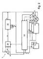
- An adaptive, self-organizing, hierarchical control system 1 for guiding and optimizing complex processes is divided into four different levels ( Fig. 1 ) to at least approximately master the complex relationships of cause and effect on the different time scales.
- the first level 10 represents the complex real process to be controlled and is realized by a controlled system 14.
- the controlled system 14 preferably includes an oven (or grate) of a coal, oil or gas power plant, a waste incineration plant or a cement works, whose combustion process to be regulated is to be guided and optimized as a complex process.
- the controlled system 14 also includes the associated adjusting devices, in particular for the supply of fuel or other material to be reacted, for example coal, oil, gas, refuse, lime or the like, and of primary air (or oxygen) and secondary air (or oxygen) ,
- the controlled system 14 further comprises various measuring devices, for example for emission parameters and the feed rates of the adjusting devices. At least one additional observation device continuously records the combustion process in the controlled system 14, in particular the flame body.
- the observation device comprises, in addition to an optical access penetrating the wall of the furnace, such as a lance or one in the EP 1 621 813 A1 disclosed apparatus, nor a camera or the like, which operates in the optical region or adjacent regions of electromagnetic waves. Preference is given to a temporally, spatially and spectrally high-resolution camera, as used for example in the WO 02/070953 A1 is described.
- the second level 20 represents an interface to the process and is realized by a process control system. It controls the adjusting devices by means of the (vectorial) manipulated variable u and queries the information of the various measuring devices and the at least one additional observation device. The measurements of the various measuring devices provide the (vectorial) actual value y, which (time-dependent) describes the current state of the controlled system 14 (ie the state variables).
- the data of the additional observation device ie the images of the flame body and the possible emissions of the walls of the furnace, are evaluated in a feature extractor 28 by means of image processing, for example according to an eigenvalue method, which is described in US Pat WO 2004/018940 A1 is described and / or by means of an information measure, as in the EP 1 967 792 A1 is described.
- the feature extractor 28 then supplies the features x determined therefrom (combined in vector).
- the second level 20 realized by the process control system provides the actual value y and the characteristics x of the third level 30 and receives the manipulated variable u.
- the third level 30 represents the management or regulation of various target variables of the process. Due to the complexity of the process, however, a monolithic MIMO control is technically and practically impossible. For this reason, unlike a monolithic controller, the third level is preferably divided into a number of smaller, more realizable functional units, which define subregions of the controller and are each implemented by a separate system of controllers ⁇ 36, C 36 , C i ⁇ from an active controller 36 and optionally further, inactive controllers in a depot.
- the regulators are preferably implemented as recurrent neural networks, since the actual value y, the characteristics x and the manipulated variable u are complexly linked with respect to cause and effect.
- Each active controller 36 compares - for its area - the actual value y with a (vectorial) setpoint w, which describes the desired state of the controlled system 4. From the control deviation e, ie the (vectorial) difference of the actual value y from the desired value w, and preferably further information, the active controller determines the (vectorial) manipulated variable u.
- the active controller 36 can, in addition to these setpoint values w, alternatively control a stable process (ie a quiet, quasi-stationary operation of the controlled system 14) or a combination.
- the control actions u to be taken with the manipulated variable u and any disturbances can be treated together as actions (intentional and unwanted actions) with which the second level 20 acts on the controlled system 14.
- the active controllers 36 work adaptively, ie they each use current data x, y to adapt their strategy to current process conditions. With the implementation of this third level 30, it is possible to perform the process according to the target specifications, the adaptivity ensures that the active controller 36 adapt to the current boundary conditions of the process by a night training can.
- a control loop is defined by the active controller 36 in the third level 30, the process control system in the second level 20 and the controlled system 14 in the first level 10.
- the fourth level 40 which in the present case is realized by a main controller 44, represents a superordinate supervision, which triggers various actions by observing the levels 20 and 30 below.
- the levels 10, 20, 30, that is to say the actual control also work without intervention of the fourth level 40, but not optimally.
- the quality ("fitness") of the active controllers 36 and also the process properties are permanently observed by the fourth level 40.
- copies of the active controllers 36 are generated and stored in the depot of the inactive controllers. The copies remaining in the repository will not be adapted further and will be available for later reuse. However, the active controllers 36 are continuously adapted to the current process conditions in the course of adaptivity.
- the depot fills with various inactive controllers, each of which is suitable for different process situations.
- the fourth level 40 now checks by analysis of the current process properties or by offline tests in a suitable clock whether a controller is available in the depot, which would be better suited for the current process state than the currently active, active controller 36. If this is the case, This previously inactive controller is activated and used and the previously active controller 36 is inactive and stored in the depot. In this way, the control system 1 can create a memory of different states (the controlled system 14) with the associated control strategies and recall at any time. Thus, one does not rely on the limited speed of adaptivity and can respond much faster to change in the process.
- the fourth level 40 In addition to checking the suitability of controllers, it is another task of the fourth level 40 to find and activate suitable parameters for the third-level controller 30 through process observation.
- the process knowledge required for this is initially introduced on the one hand in the form of known expert knowledge and on the other hand supplemented by our own active process experience. With increasing duration The process experience grows and ultimately dominates the process knowledge.
- the fourth level 40 can now define, for example, appropriate setpoints .or work areas of the controllers in the third level 30, and guide the process as it works best according to the present process knowledge.
- the main controller 44 in the fourth level 40, the active controllers 36 in the third level 30, the process control system in the second level 20 and the controlled system 14 in the first level 10 define a complex control loop, ie several control loops coupled together.
- a partial aspect is the testing of controllers, which will now be explained with reference to a subarea with a controller 36.
- the main controller 44 manages not only the depot with the controllers, but also several simulators S 1 , S 2 , .... S n , each representing a (process) model of the controlled system 14 and simulate them.
- the simulators S 1 , S 2 ,... S n are based on differently configured models for the (combustion) process of the controlled system 14, in particular with regard to different situations.
- the simulators S 1 , S 2 ,. S n are preferably implemented as recurrent neural networks. It is always possible to add or remove further simulators S i .
- the main controller 44 manages only a few simulators S 1 , S 2 , .... S n , for example a single simulator S 1 , which are based solely on expert knowledge as the only process knowledge. With increasing process experience, the main controller 44 then preferably creates further simulators S 1 , S 2 , .... S n .
- the main controller 44 initially trains ( Fig. 2 ) the individual simulators S 1 , S 2 ,... S n evolutionary, in that the deviation of the prognosis y 'for the actual value y from the real actual value y defines a "fitness" which is to be optimized in each case.
- the simulators S 1 , S 2 , .... S n receive besides the real actual value y also the further features x.
- simulators S 1 , S 2 ,... S n which only achieve low fitness, are discarded by the main controller 44.
- the main controller 44 is now developing ( Fig. 3 ) a set of (inactive) regulators ⁇ C i , C 36 ⁇ , consisting of new controllers C i , which are subjected to evolutionary search strategies (ie elements of this set created by the main controller 44 and, if the fitness is too low again, elements of this set), and all controllers C 36 that were previously active controllers 36 and that are excluded from the evolutionary search strategies for new controllers C i .
- evolutionary search strategies ie elements of this set created by the main controller 44 and, if the fitness is too low again, elements of this set
- all controllers C 36 that were previously active controllers 36 and that are excluded from the evolutionary search strategies for new controllers C i .
- the main controller 10 tests the set of regulators ⁇ C i , C 36 ⁇ on the simulators S 1 , S 2 , .... S n .
- the controller C i or C 36 is sought which, on average, uses all the simulators S 1 , S 2 , .... S n to best match their forecasts y 'over time with the courses of the desired values w (ie the one Controller with which the setpoints w are best reached).
- the "fitness" of such a controller C i or C 36 therefore results from the (simulated) control deviations e of the controller C i or C 36 in closed control loops on all simulators S 1 , S 2 , .... S n . Again, the features x are taken into account.
- the controller C i or C 36 thus found is designated as the best controller C 1 . Since the various simulators S 1 , S 2 , .... S n . Based on different process models and the best controller C 1 was found on average across all simulators used S 1 , S 2 , .... S n , the best controller C 1 contains characteristics of different process models.
- the best (inactive) controller C 1 is now compared by the main controller 44 with the active in the third level 30 controller 36, for example, in terms of the mean deviation e.
- the master controller 44 then replaces the active controller 36 with the best controller C i .
- the previous active regulator 36 returns to the set of inactive regulators ⁇ C i , C 36 ⁇ .
- the main controller 44 takes the training ( Fig. 2 ) of the simulators S 1 , S 2 , .... S n and the testing ( Fig. 3 ) of the set of regulators ⁇ C i , C 36 ⁇ in certain cycles with the respective current actual value y (and the current characteristics x) before, for example, every eight hours to an adapted to the medium-term changes in the state of the controlled system 14 active regulator 36 to get.
- control systems with only one (active) controller have the disadvantage that, in the event of a major change in the process, the night training of the controller becomes too time-consuming.
- Another partial aspect is the definition of the subregions of the control and distribution under the active controllers 36, 36 ', 36 “, 36"', 36 “”.
- the subregions of the control are assigned to smaller and more easily controllable and modelable subprocesses of the complex process ( Fig. 4 ).
- the division is preferably not static, but changes dynamically by means of an automatic problem composition (APD).
- APD automatic problem composition
- the self-learning, self-organizing system for automatic problem decomposition (on main controller 44) automatically analyzes the problem structure of the complex high-dimensional process and designs an appropriate structure of controllers 36, 36 ', 36 ", 36"', 36 "”.
- this concept is characterized by greater transparency and performance and can be learned and adapted more quickly.
- This structuring of the process takes place on the basis of the present as extensive and informative process data from a database in parallel by means of at least one, preferably all five methods described below.
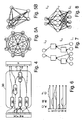
- Fig. 7 In the co-evolutionary bottom-up structure search ( Fig. 7 ), in contrast to the previous methods, the complex overall system is modeled by combining numerous small functional units. For this purpose, co-evolutionary algorithms are used, which generate a suitable combination of the subsystems based on the aberration of predefined target channels. The thus found model structure corresponds to the problem decomposition.
- Fig. 7 is exemplified from bottom to top of the input layer L 1 , two hidden layers L 2 with simple learning approximators and the output layer L 3 shown. The hidden layers L 2 may be present in a different number.
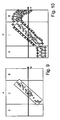
- problem decomposition is modeled by network pruning ( Fig. 8 )
- suitable adaptive function approximators such as neural networks, similar as in the EP 2 080 953 A1 described.
- By analyzing the internal model structure can then be concluded on the underlying problem structure of the process.
- the input layer L 1 , the hidden layer L 2 and the output layer L 3 are shown from bottom to top.
- a partial aspect is also the problem that the process knowledge, which initially consists only of expert knowledge, is enriched only slowly by process experience and this is not evenly distributed over the possible states (the controlled system 14), ie in the data space of the process.
- informative data is available only in the normal working area - in an uneven distribution - but there are no or far too few data on the abnormal fault areas.
- a controller can not learn an adequate strategy and will be in the Online operation behaves unpredictably. Therefore, an adaptive controller (NFQ) is proposed, which is trained based on the measured process data present in the data space and in which artificial data points are introduced into the data space to prevent the controller from developing any strategies for regions with poor data support.
- Existing expert knowledge can be integrated explicitly.
- the adaptive controller is also suitable for training on closed-loop data sets.
- the adaptive controller is realized by an adaptive neural multi-layered network which is trained by a gradient descent-based or evolutionary method.
- MIMO system input variables and several manipulated variables
- MISO, SIMO mixed forms
- the adaptive controller is based on reinforcement learning and does not directly depict the control strategy, but first determines the value of actuators in different process situations.
- the value of a control intervention is determined by means of a reward function defined by the operator.
- the training of the controller is based initially only on existing in the data room measurements of different process variables.
- the data space is not complete in the sense that on the one hand all conceivable process situations are included (rare disorders or exceptional situations are usually missing).
- normally not all possible control interventions are included in all process situations, since these industrial processes are usually regulated.
- the drawing ( Fig. 9 ) illustrates the two categories of missing data for a simple SISO case with a manipulated variable u and an input e.
- the existing measurement data (circles in FIGS. 9 and 10 ) in the Dataroom area I with known process situations (ie existing process knowledge) not equally well distributed.
- the adaptive controller is also used in regions that are supported by real experiences.
- the controller relies on the impressed expert knowledge. If real process experiences occur during operation with the controller, they are included as normal in the training and increasingly dominate the expert knowledge. This ensures that real process experiences over time prevail over expert knowledge.
Description
Die Erfindung betrifft ein Regelsystem mit den Merkmalen des Oberbegriffs des Anspruches 1.The invention relates to a control system having the features of the preamble of claim 1.
Ein hierarchisches Regelsystem dieser Art ist aus der
Komplexe Realwelt-Prozesse zeichnen sich durch verschiedene Eigenschaften aus, die eine Regelung bzw. Optimierung erschweren. Die Prozesse sind zunächst allein durch die Anzahl der verfügbaren Mess-, Regel- und Stellgrößen sehr komplex. Darüber hinaus sind diese Prozesse meist zeitvariant, d.h., aufgrund externer und interner Einflüsse (Jahreszeiten, Materialqualitäten, Betriebszustände) entstehen zeitlich wechselnde Zusammenhänge in den Prozessdaten. Ein Regelsystem muss daher adaptiv sein und ständig angepasst werden.Complex real-world processes are characterized by various properties that make regulation or optimization more difficult. At first, the processes are very complex only due to the number of available measuring, control and manipulated variables. In addition, these processes are usually time-variant, that is, due to external and internal influences (seasons, material qualities, operating conditions) arise temporally changing relationships in the process data. A control system must therefore be adaptive and constantly adapted.
Bei einem aus der
Die
Der vorliegenden Erfindung liegt die Aufgabe zugrunde, ein Regelsystem der eingangs genannten Art zu verbessern. Diese Aufgabe wird durch ein Regelsystem mit den Merkmalen des Anspruches 1 gelöst. Weitere vorteilhafte Ausgestaltungen sind Gegenstand der Unteransprüche.The present invention has for its object to improve a control system of the type mentioned. This object is achieved by a control system having the features of claim 1. Further advantageous embodiments are the subject of the dependent claims.
Ausgangspunkt ist der komplexe, also durch verschiedenste Wechselwirkungen äußerst nicht-triviale Zusammenhang zwischen Ursache und Winkung im Prozess. Die hierarchische Aufteilung des Regelsystems in verschiedene Ebenen erlaubt ein besseres Verständnis des Prozesses und eine optimierte Adaption des Regelsystems an den aktuelle Zustand des Prozesses.The starting point is the complex, that is, through a variety of interactions extremely non-trivial connection between cause and angle in the process. The hierarchical division of the control system into different levels allows a better understanding of the process and an optimized adaptation of the control system to the current state of the process.
Zum Einen können dadurch aktive Regler schneller adaptiert werden, indem der Hauptregler im Hintergrund verschiedene Regler prüft und dabei früher aktive Regler berücksichtigt. Damit wird vermieden, dass durch ein langes Nachtraining des aktiven Reglers dieser erst zur Verfügung steht, wenn er schon nicht mehr wegen einer Änderung des Prozesses genutzt werden kann. Für die Regelung wird vorzugsweise ein rekurrentes neuronales Netzwerk (bzw. mehrere miteinander verknüpfte Netzwerke) verwendet, welches mittels eines evolutionären Ansatzes trainiert wird, der als Optimierungskriterium die mittlere Regelabweichung minimiert.On the one hand, active controllers can be adapted more quickly by the main controller checking different controllers in the background, taking into account previously active controllers. This avoids the fact that a long night training of the active controller makes this available only when it can no longer be used because of a change in the process. For the regulation, preferably a recurrent neural network (or several interconnected networks) is used, which is trained by means of an evolutionary approach, which minimizes the mean deviation as an optimization criterion.
Bei einer entsprechenden Betriebsdauer des Regelsystems liegen ausreichend viele Daten vor, um ausreichend gute Simulatoren zu schaffen, welche die Regelstrecke mit unterschiedlich konfigurierten Prozessmodellen simulieren. Mit dem Einsatz von Simulatoren kann eine Menge von alten und neuen Reglern getestet werden, bevor ein Einsatz an der Regelstrecke erfolgt. Eine Störung des laufenden Betriebs des Regelkreises wird dadurch vermieden. Die Verwendung mehrerer Simulatoren reduziert Fehler und Abweichungen vom realen Verhalten der Regelstrecke und berücksichtigt unterschiedliche Situationen besser. Ein entsprechend entwickelter Regler beruht somit auf mehreren Prozessmodellen. Es wird vorzugsweise derjenige Regler gesucht, mit dem die Sollwerte am besten zu erreichen sind. Die Beibehaltung früher aktiver Regler erleichtert bei einer Wiederkehr bestimmter Zustände und Zeitverläufe die Entwicklung des besten Reglers. Zudem werden Rechenzeiten und -leistungen gespart. Das Training der Simulatoren und die Entwicklung eine Menge von Reglern wird von einem Hauptregler vorgenommen und überwacht, vorzugsweise in bestimmten Zyklen, die auf die Dynamik der Regelstrecke abgestimmt sind. Optimierungen des Regelkreises sind durch zusätzliche Informationen, insbesondere Bildverarbeitung, möglich und gehen beispielsweise in die Simulatoren und/oder in die Entwicklung der Regler und/oder in die Sollwerte ein.Given a corresponding operating time of the control system, sufficient data are available to create sufficiently good simulators which simulate the controlled system with differently configured process models. With the use of simulators, a lot of old and new controllers can be tested before they are used on the controlled system. A disturbance of the current operation of the control loop is thereby avoided. The use of several simulators reduces errors and deviations from the real behavior of the controlled system and better considers different situations. A correspondingly developed controller is thus based on several process models. Preferably, the controller is sought with which the setpoint values are best achieved. The retention of early active controllers facilitates the development of the best controller when certain states and time courses return. In addition, computing times and services are saved. The training of the simulators and the development of a large number of controllers is performed and monitored by a main controller, preferably in certain cycles, which are tuned to the dynamics of the controlled system. Optimizations of the control loop are supported by additional information, in particular Image processing, possible and enter, for example, in the simulators and / or in the development of the controller and / or in the setpoints.
Zum Zweiten kann die Regelung unter verschiedenen aktiven Reglern aufgeteilt werden, welchen Teilprozesse des komplexen Prozesses zugeordnet sind. Die Aufteilung der Regelung ändert sich vorzugsweise dynamisch mittels einer automatischen Problemdekomposition. Der Hauptregler analysiert den Datenraum des Prozesses und bildet Regler für Teilbereiche, die in sich stärkere Zusammenhänge zeigen.Second, the regulation may be divided among different active regulators to which sub-processes of the complex process are assigned. The division of the control preferably changes dynamically by means of an automatic problem decomposition. The main controller analyzes the data space of the process and forms controls for subregions, which show stronger connections in themselves.
Zum Dritten können, wenn bei geringen Prozesserfahrungen schwach oder gar nicht vertretene Regionen im Datenraum auftreten, diese Regionen mit künstlichen Datenpunkten gefüllt oder abgegrenzt werden.Third, if weak or unrepresented regions in the data room occur during low process experiences, these regions can be filled or delineated with artificial data points.
Die Erfindung kann bei verschiedenen stationären thermodynamischen Anlagen, insbesondere Kraftwerken, Müllverbrennungsanlagen und Zementwerken, eingesetzt werden. Ein Einsatz des erfindungsgemäßen Regelsystems ist auch in anderen technischen Gebieten denkbar. So ist die Erfindung nicht auf thermische Prozesse beschränkt, sondern kann auch allgemein in der mechanischen oder chemischen Verfahrenstechnik angewendet werden, beispielsweise in Raffinerien oder Spaltöfen. Prinzipiell kann auch bei fehlender oder abgeschalteter Rückkopplung der enthaltenen Regelkreis der verbliebene Teil des Regelsystems für eine Systemidentifikation und Systembeschreibung eingesetzt werden, d.h. zur Informationsgewinnung.The invention can be used in various stationary thermodynamic systems, in particular power plants, waste incineration plants and cement works. An application of the control system according to the invention is also conceivable in other technical fields. Thus, the invention is not limited to thermal processes, but can also be applied generally in mechanical or chemical engineering, for example in refineries or cracking furnaces. In principle, the remaining part of the control system can be used for a system identification and system description, even in the absence or disconnected feedback of the contained control loop, i. E. for information gathering.
Im folgenden ist die Erfindung anhand eines in der Zeichnung dargestellten Ausführungsbeispiels näher erläutert. Es zeigen
- Fig. 1
- eine schematische Darstellung des hierarchischen Aufbaus des Regelsystems,
- Fig. 2
- eine schematische Darstellung des Regelsystems während des Trainings der Simulatoren,
- Fig. 3
- eine schematische Darstellung des Regelsystems während der Entwicklung der Menge von Reglern,
- Fig. 4
- eine schematische Darstellung der Aufteilung der Teilbereiche der Regelung,
- Fig. 5A
- eine schematische Darstellung der Mutual-Information basierten Problemzerlegung bei der Berechnung der gegenseitige Informationsgehalte (mutual information),
- Fig. 5B
- eine schematische Darstellung der Mutual-Information basierten Problemzerlegung bei der Problemdekomposition,
- Fig. 6
- eine schematische Darstellung der Dynamik-orientierte Problemzerlegung,
- Fig. 7
- eine schematische Darstellung der Co-Evolutionäre bottom-up-Struktursuche,
- Fig. 8
- eine schematische Darstellung der Problemdekomposition durch Netzwerkpruning,
- Fig. 9
- eine schematische Darstellung des unvollständigen Datenraums, und
- Fig. 10
- eine schematische Darstellung des Datenraums mit künstlichen Datenpunkten.
- Fig. 1
- a schematic representation of the hierarchical structure of the control system,
- Fig. 2
- a schematic representation of the control system during the training of the simulators,
- Fig. 3
- a schematic representation of the control system during the development of the set of controllers,
- Fig. 4
- a schematic representation of the division of the subregions of the scheme,
- Fig. 5A
- a schematic representation of the mutual information based problem decomposition in the calculation of the mutual information contents (mutual information),
- Fig. 5B
- a schematic representation of the mutual information based problem decomposition in the problem decomposition,
- Fig. 6
- a schematic representation of the dynamics-oriented problem decomposition,
- Fig. 7
- a schematic representation of the co-evolutionary bottom-up structure search,
- Fig. 8
- a schematic representation of the problem decomposition by network pruning,
- Fig. 9
- a schematic representation of the incomplete data space, and
- Fig. 10
- a schematic representation of the data space with artificial data points.
Ein lernfähiges, selbstorganisierendes, hierarchisches Regelsystem 1 zur Führung und Optimierung komplexer Prozesse ist in vier verschiedene Ebenen aufgeteilt (
Die erste Ebene 10 repräsentiert den zu regelnden, komplexen, realen Prozess und wird durch eine Regelstrecke 14 verwirklicht. Die Regelstrecke 14 umfasst vorzugsweise einen Ofen (oder ein Rost) eines Kohle-, Öl- oder Gaskraftwerks, einer Müllverbrennungsanlage oder eines Zementwerks, dessen zu regelnder Verbrennungsprozess als komplexer Prozess geführt und optimiert werden soll. Die Regelstrecke 14 umfasst auch die zugehörigen Stellvorrichtungen, insbesondere für die Zufuhr von Brennstoff oder anderem umzusetzenden Material, beispielsweise Kohle, Öl, Gas, Müll, Kalk oder dergleichen, sowie von Primärluft (bzw. -sauerstoff) und Sekundärluft (bzw. -sauerstoff). Die Regelstrecke 14 umfasst ferner verschiedene Messvorrichtungen, beispielsweise für Emissionsparameter und die Zufuhrraten der Stellvorrichtungen. Wenigstens eine zusätzliche Beobachtungsvorrichtung erfasst laufend bildlich den Verbrennungsprozess in der Regelstrecke 14, insbesondere den Flammenkörper. Die Beobachtungsvorrichtung umfasst neben einem die Wand des Ofens durchdringenden optischen Zugang, wie beispielsweise einer Lanze oder einer in der
Die zweite Ebene 20 repräsentiert ein Interface zum Prozess und wird durch ein Prozessleitsystem realisiert. Sie steuert die Stellvorrichtungen mittels der (vektoriellen) Stellgröße u an und fragt die Informationen der verschiedenen Messvorrichtungen und der wenigstens einen zusätzlichen Beobachtungsvorrichtung ab. Die Messungen der verschiedenen Messvorrichtungen liefern den (vektoriellen) Istwert y, welcher (zeitabhängig) den aktuellen Zustand der Regelstrecke 14 beschreibt (d.h. die Zustandsvariablen). Die Daten der zusätzlichen Beobachtungsvorrichtung, also die Bilder des Flammenkörpers und der eventuellen Emissionen der Wände des Ofens werden in einem Merkmalsextraktor 28 mittels Bildverarbeitung ausgewertet, beispielsweise nach einem Eigenwert-Verfahren, das in der
Die dritte Ebene 30 repräsentiert die Führung bzw. Regelung verschiedener Zielgrößen des Prozesses. Aufgrund der Komplexität des Prozesses ist jedoch eine monolithische MIMO-Regelung technisch und praktisch nicht möglich. Aus diesem Grunde wird die dritte Ebene vorzugsweise - im Unterschied zu einem monolithischen Regler - in mehrere kleinere besser realisierbare Funktionseinheiten aufgeteilt, die Teilbereichen der Regelung definieren und jeweils durch ein separates System von Reglern {36, C36, Ci} realisiert werden, bestehend aus einem aktiven Regler 36 und gegebenenfalls weiteren, inaktiven Reglern in einem Depot. Vorzugsweise sind die Regler als rekurrente neuronale Netzwerke implementiert, da der Istwert y, die Merkmale x und die Stellgröße u hinsichtlich Ursache und Wirkung komplex miteinander verknüpft sind. Jeder aktive Regler 36 vergleicht - für seinen Bereich - den Istwert y mit einem (vektoriellen) Sollwert w, welcher den gewünschten Zustand der Regelstrecke 4 beschreibt. Aus der Regelabweichung e, also der (vektoriellen) Differenz des Istwertes y vom Sollwert w, und vorzugsweise weiteren Informationen ermittelt der aktive Regler 36 die (vektorielle) Stellgröße u. Der aktive Regler 36 kann außer auf diese Sollwerte w alternativ auf einen stabilen Prozess (d.h. einen ruhigen, quasistationären Betrieb der Regelstrecke 14) hin regeln oder auf eine Kombination. Die mit der Stellgröße u vorzunehmenden Stelleingriffe sowie etwaige Störungen können gemeinsam als Aktionen (gewollte und ungewollte Aktionen) behandelt werden, mit welcher die zweite Ebene 20 auf die Regelstrecke 14 einwirkt Die aktiven Regler 36 arbeiten adaptiv, d.h., sie nutzen jeweils aktuelle Daten x, y, um ihre Strategie den aktuellen Prozessgegebenheiten anzupassen. Mit der Umsetzung dieser dritten Ebene 30 ist es möglich, den Prozess entsprechend der Ziel vorgaben zu führen, wobei die Adaptivität dafür sorgt, dass sich die aktiven Regler 36 den aktuellen Randbedingungen des Prozesses durch ein Nachtraining anpassen können. Ein Regelkreis wird durch den aktiven Regler 36 in der dritten Ebene 30, das Prozessleitsystem in der zweiten Ebene 20 und die Regelstrecke 14 in der ersten Ebene 10 definiert.The
Die vierte Ebene 40, welche vorliegend durch einen Hauptregler 44 realisiert wird, repräsentiert eine übergeordnete Aufsicht, welche durch Beobachtung der darunter liegenden Ebenen 20 und 30 verschiedene Aktionen auslöst. Dabei arbeiten die Ebenen 10, 20, 30, also die eigentliche Regelung, auch ohne einen Eingriff der vierten Ebene 40, aber nicht optimal. Beispielsweise werden von der vierten Ebene 40 die Güte ("Fitness") der aktiven Regler 36 und auch die Prozesseigenschaften dauerhaft beobachtet. Bei entsprechend großen Abweichungen oder Veränderungen werden Kopien der aktiven Regler 36 erzeugt und in dem Depot der inaktiven Regler verwahrt. Die im Depot verbleibenden Kopien werden nicht weiter adaptiert und stehen zur späteren erneuten Anwendung zur Verfügung. Die aktiven Regler 36 werden jedoch im Zuge der Adaptivität permanent weiter den aktuellen Prozessgegebenheiten angepasst. Auf diese Weise füllt sich das Depot mit verschiedenen inaktiven Reglern, die jeweils für unterschiedliche Prozesssituationen geeignet sind. Die vierte Ebene 40 prüft nun durch Analyse der aktuellen Prozesseigenschaften oder durch Offlinetests in einem geeigneten Takt, ob nicht im Depot ein Regler bereit liegt, der für den aktuellen Prozesszustand besser geeignet wäre als der aktuell arbeitende, aktive Regler 36. Ist dies der Fall, wird dieser bislang inaktive Regler aktiviert und genutzt und der bislang aktive Regler 36 wird inaktiv und im Depot eingelagert. Auf diese Weise kann sich das Regelsystem 1 ein Gedächtnis verschiedener Zustände (der Regelstrecke 14) mit den zugehörigen Reglerstrategien anlegen und jederzeit abrufen. Somit ist man nicht auf die begrenzte Geschwindigkeit der Adaptivität angewiesen und kann deutlich schneller auf Wechsel im Prozess reagieren.The
Neben der Prüfung der Eignung von Reglern ist es eine weitere Aufgabe der vierten Ebene 40, durch Prozessbeobachtung geeignete Parameter für die Regler der dritten Ebene 30 zu finden und zu aktivieren. Das dazu erforderliche Prozesswissen wird einerseits in Form von bekanntem Expertenwissen ursprünglich eingebracht und andererseits durch eigene aktive Prozesserfahrungen ergänzt. Mit zunehmender Dauer des Prozesses wächst die Prozesserfahrung an und dominiert schließlich das Prozesswissen. Mit Hilfe des Prozesswissens kann die vierte Ebene 40 nun zum Beispiel geeignete Sollwerte .oder Arbeitsbereiche der Regler in der dritten Ebene 30 definieren und den Prozess so führen, wie es nach dem vorliegenden Prozesswissen am besten funktioniert. Letztendlich definieren der Hauptregler 44 in der vierten Ebene 40, die aktiven Regler 36 in der dritten Ebene 30, das Prozessleitsystem in der zweiten Ebene 20 und die Regelstrecke 14 in der ersten Ebene 10 einen komplexen Regelkreis, d.h. mehrere miteinander gekoppelte Regelkreise.In addition to checking the suitability of controllers, it is another task of the
Im folgenden sind nun Teilaspekte des Regelsystems 1 genauer beschrieben.In the following, partial aspects of the control system 1 will now be described in more detail.
Ein Teilaspekt ist die Prüfung von Reglern, welche nun anhand eines Teilbereichs mit einem Regler 36 erläutert werden soll. Der Hauptregler 44 verwaltet nicht nur das Depot mit den Reglern, sondern auch mehrere Simulatoren S1, S2, .... Sn, die jeweils ein (Prozess-)Modell der Regelstrecke 14 darstellen und diese simulieren. Die Simulatoren S1, S2, .... Sn beruhen auf - insbesondere in Hinblick auf unterschiedliche Situationen - unterschiedlich konfigurierten Modellen für den (Verbrennungs-) Prozess der Regelstrecke 14. Die Simulatoren S1, S2, .... Sn sind vorzugsweise als rekurrente neuronale Netzwerke implementiert. Es ist jederzeit möglich, weitere Simulatoren Si hinzuzufügen oder zu entfernen. Ganz am Anfang, wenn noch keine Prozesserfahrungen vorhanden sind, verwaltet der Hauptregler 44 nur wenige Simulatoren S1, S2, .... Sn, beispielsweise einen einzigen Simulator S1, welche allein auf dem Expertenwissen als einzigem Prozesswissen beruhen. Mit zunehmender Prozesserfahrung erstellt der Hauptregler 44 dann vorzugsweise weitere Simulatoren S1, S2, .... Sn.A partial aspect is the testing of controllers, which will now be explained with reference to a subarea with a
Der Hauptregler 44 trainiert zunächst (
Der Hauptregler 44 entwickelt nun (
Der beste (inaktive) Regler C1 wird nun vom Hauptregler 44 mit dem in der dritten Ebene 30 aktiven Regler 36 verglichen, beispielsweise hinsichtlich der mittleren Regelabweichung e. Je nach zeitlicher Entwicklung des Zustandes der Regelstrecke 14 (d.h. je nach Prozesssituation und Prozesshistorie) kann es sein, dass der beste Regler C1 auch besser als der aktive Regler 36 ist. Der Hauptregler 44 ersetzt dann den aktiven Regler 36 durch den besten Regler Ci. Der bisherige aktive Regler 36 kehrt in die Menge von inaktiven Reglern {Ci, C36} zurück. Sofern irgendwann wieder ein Zustand der Regelstrecke 14 erreicht wird, für den dieser früher aktive Reglern C36 bereits gut war, wird er auch im Test an den Simulatoren S1, S2, .... Sn eine sehr hohe "Fitness" erhalten und wieder zum aktiven Regler 36 werden.The best (inactive) controller C 1 is now compared by the
Der Hauptregler 44 nimmt das Training (
Ein weiterer Teilaspekt ist die Definition der Teilbereiche der Regelung und Aufteilung unter den aktiven Reglern 36, 36', 36", 36"', 36"". Die Teilbereiche der Regelung sind kleineren und einfacher regelbaren und modellierbaren Teilprozessen des komplexen Prozesses zugeordnet (
Bei der Mutual-Information basierten Problemzerlegung (
Bei der Dynamik-orientierten Problemzerlegung (
Bei der Co-Evolutionären bottom-up-Struktursuche (
Bei der Problemdekomposition durch Rewarddekomposition werden werden zunächst hypothetische Problemzerlegungen konstruiert. Anschließend wird ein Verfahren zur automatischen Rewarddekomposition zur Lösung des Credit Assignment Problemes genutzt, um die Güte der hypothetischen Problemzerlegung zu bewerten. Diese Bewertung wird anschließend von einem stochastischen Suchverfahren genutzt, um die optimale Problemzerlegungen zu finden.In problem decomposition by reward decomposition, hypothetical problems are first constructed. Subsequently, a method for automatic reward decomposition to solve the credit assignment problem is used to assess the merit of the hypothetical problem decomposition. This score is then used by a stochastic search engine to find the optimal problem decomposition.
Schließlich modelliert die Problemdekomposition durch Netzwerkpruning (
Jedes dieser Verfahren liefert eine Hypothese für die Problemzerlegung. In einem anschließenden Schritt werden diese Dekompositionsvorschläge miteinander verglichen und eine gemeinsame Lösung abgeleitet, welche die Aufteilung in Teilbereiche vornimmt und den Reglern 36, 36', 36", 36"', 36"" zuordnet. Hierzu können verschiedene Ansätze genutzt werden, wie beispielsweise eine automatisierte Mehrheitsentscheidung. Wenn der Prozess schon länger läuft, also Prozesserfahrung vorliegt, erfolgt die automatische Problemdekomposition sinnvollerweise auf einer größeren Zeitskala als die oben beschriebene Prüfung der Regler durch den Hauptregler 44.Each of these methods provides a hypothesis for problem decomposition. In a subsequent step, these decomposition proposals are compared with each other and a common solution is derived, which divides into subregions and assigns them to the
Ein Teilaspekt ist auch die Problematik, dass das Prozesswissen, welches anfänglich nur aus Expertenwissen besteht, nur langsam durch Prozesserfahrung angereichert wird und diese nicht gleichmäßig über die möglichen Zustände (der Regelstrecke 14), d.h. im Datenraum des Prozesses, verteilt ist. So liegen nur für den normalen Arbeitsbereich entsprechend informative Daten - in ungleichmäßiger Verteilung - vor, jedoch keine oder viel zu wenige Daten zu den abnormalen Störungsbereichen. In Folge dessen kann ein Regler keine adäquate Strategie erlernen und wird sich im Onlinebetrieb unvorhersehbar verhalten. Daher wird ein adaptiver Regler (NFQ) vorgeschlagen, welcher auf Grundlage der im Datenraum vorhandenen, gemessenen Prozessdaten trainiert wird, und bei welchem künstliche Datenpunkte in den Datenraum eingeführt werden, um zu verhindern, dass der Regler beliebige Strategien für Regionen mit schlechter Datenstützung entwickelt. Vorhandenes Expertenwissen kann explizit integriert werden. Der adaptive Regler ist auch zum Training auf closed-loop-Datensätzen geeignet.A partial aspect is also the problem that the process knowledge, which initially consists only of expert knowledge, is enriched only slowly by process experience and this is not evenly distributed over the possible states (the controlled system 14), ie in the data space of the process. Thus, informative data is available only in the normal working area - in an uneven distribution - but there are no or far too few data on the abnormal fault areas. As a result, a controller can not learn an adequate strategy and will be in the Online operation behaves unpredictably. Therefore, an adaptive controller (NFQ) is proposed, which is trained based on the measured process data present in the data space and in which artificial data points are introduced into the data space to prevent the controller from developing any strategies for regions with poor data support. Existing expert knowledge can be integrated explicitly. The adaptive controller is also suitable for training on closed-loop data sets.
Der adaptive Regler wird durch ein lernfähiges neuronales mehrschichtiges Netzwerk realisiert, welches durch ein gradientenabstiegsbasiertes oder evolutionäres Verfahren trainiert wird. Es sind dabei mehrere Eingabevariablen und mehrere Stellgrößen (MIMO-System), einfache SISO-Systeme und auch Mischformen (MISO, SIMO) möglich. Der adaptive Regler basiert auf dem Reinforcement-Learning und bildet nicht direkt die Regelstrategie ab, sondern ermittelt zunächst den Wert (Value) von Stelleingriffen in verschiedenen Prozesssituationen. Der Wert eines Stelleingriffes wird anhand einer vom Betreiber definierten Rewardfunktion ermittelt. Diese Rewardfunktion ist die mathematische Notation des Regelzieles, z.B. minimale Regelabweichung einer Zielgröße e = - abs(w-y). Durch Vergleich der Werte unterschiedlicher Stelleingriffe in der gleichen Prozesssituation kann der Regler herausfinden, welche Strategie (Policy) besser ist, und kann diese dann auch praktisch anwenden.The adaptive controller is realized by an adaptive neural multi-layered network which is trained by a gradient descent-based or evolutionary method. Several input variables and several manipulated variables (MIMO system), simple SISO systems and mixed forms (MISO, SIMO) are possible. The adaptive controller is based on reinforcement learning and does not directly depict the control strategy, but first determines the value of actuators in different process situations. The value of a control intervention is determined by means of a reward function defined by the operator. This reward function is the mathematical notation of the control target, e.g. minimum deviation of a target size e = - abs (w-y). By comparing the values of different control interventions in the same process situation, the controller can find out which strategy (policy) is better and then apply it in practice.
Das Training des Reglers basiert zunächst nur auf den im Datenraum vorhandenen Messungen verschiedener Prozessgrößen. Typischerweise ist der Datenraum nicht vollständig in dem Sinne, dass einerseits alle denkbaren Prozesssituationen enthalten sind (seltene Störungen oder Ausnahmesituationen fehlen meist). Andererseits werden normalerweise auch nicht in allen Prozesssituationen alle möglichen Stelleingriffe enthalten sein, da diese industriellen Prozesse meist geregelt sind. Die Zeichnung (
Um sicherzustellen, dass in den unbekannten Regionen keine unerwünschten Extrapolationen des Reglerverhaltens auftreten, werden nun auch dort künstliche Daten eingefügt. Dies erfolgt einerseits in der Region nicht getesteter Stellaktionen im Datenraum-Gebiet I mit bekannten Prozesssituationen (Kreuze in Datenraum-Gebiet I in
Auf diese Weise kann sichergestellt werden, dass der adaptive Regler in Regionen, die durch reale Erfahrungen gestützt werden, diese auch genutzt werden. In bislang nicht explorierten Regionen stützt sich der Regler auf das aufgeprägte Expertenwissen. Ergeben sich während des laufenden Betriebes mit dem Regler reale Prozesserfahrungen, werden diese ganz normal in das Training einbezogen und dominieren zunehmend das Expertenwissen. Somit wird sichergestellt, dass reale Prozesserfahrungen sich mit der Zeit auch gegenüber dem Expertenwissen durchsetzen.In this way, it can be ensured that the adaptive controller is also used in regions that are supported by real experiences. In previously unexplored regions, the controller relies on the impressed expert knowledge. If real process experiences occur during operation with the controller, they are included as normal in the training and increasingly dominate the expert knowledge. This ensures that real process experiences over time prevail over expert knowledge.
- 11
- Regelsystemcontrol system
- 1010
- erste Ebenefirst floor
- 1414
- Regelstreckecontrolled system
- 2020
- zweite Ebenesecond level
- 2828
- Merkmalsextraktorfeature extractor
- 3030
- dritte EbeneThird level
- 36, 36', 36", 36"', 36""36, 36 ', 36 ", 36"', 36 ""
- aktiver Regleractive controller
- 4040
- vierte Ebenefourth level
- 4444
- Hauptreglermaster controller
- A, B, C, D, E, F, G, HA, B, C, D, E, F, G, H
- Kanal, KnotenChannel, node
- Ci, C36, C1 C i , C 36 , C 1
- Reglerregulator
- ee
- Regelabweichungdeviation
- I, III, II
- Datenraum-GebietData space area
- L1 L 1
- Eingabeschichtinput layer
- D2 D 2
- verdeckte Schichthidden layer
- L3 L 3
- Ausgabeschichtoutput layer
- Si S i
- Simulatorsimulator
- uu
- Stellgrößemanipulated variable
- ww
- Sollwertsetpoint
- xx
- Merkmalfeature
- yy
- Istwertactual value
- y'y '
- Prognose des IstwertesForecast of the actual value
- { }{}
- Mengeamount
Claims (12)
- A control system for a complex, real process to be controlled, particularly for controlling a combustion process in a power plant, a waste incineration installation or a cement works, being hierarchically split into various levels (10, 20, 30, 40), wherein a first level (10) represents the complex, real process to be controlled and is implemented by the controlled system (14), a second level (20) represents an interface to the process and is realized by a process control system, a third level (30) represents the control of the process and is realized by the at least one active controller (36), and a fourth level (40) represents a superordinate supervisor and is realized by a principal controller (44), characterized in that the principal controller (44) is adapted to train simulators (S1, S2, ..., Sn) simulating the controlled system (14), to develop a set of controllers ({Ci, C36}), and to test said set of controllers on the simulators (S1, S2, ..., Sn) in order to find the best controller (C1) and compare it with the active controller (36) and to replace it if necessary, wherein the set of controllers ({Ci, C36}) new controllers (Ci) and also controllers (C36) which were active controllers (36) earlier, wherein the active controller (36) uses the control error (e) between the actual value (y) of the controlled system (14) and the setpoint value (w) in order to ascertain the manipulated variable (u).
- The control system as claimed in claim 1, characterized in that the active controller (36) is based on a recurrent neural network.
- The control system as claimed in one of the preceding claims, characterized in that a feature extractor (28) is provided which performs image processing for the controlled system (14) and ascertains features (x) therefrom.
- The control system as claimed in one of the preceding claims, characterized in that the principal controller (44) trains the individual simulators (S1, S2, ..., Sn) in evolutionary fashion using a recurrent neural network by virtue of the discrepancy in the forecast (y') for the actual value (y) from a real actual value (y) defining a fitness which needs to be optimized in each case.
- The control system as claimed in one of the preceding claims, characterized in that the principal controller (44) tests the set of controllers ({Ci, C36}) on the simulators (S1, S2, ..., Sn), wherein a search is performed for that controller (Ci, C36) which, on average over all the simulators (S1, S2, ..., Sn) used, best matches the forecasts (y') of the latter in the time profile to the profiles of the setpoint values (w).
- The control system as claimed in claim 5, characterized in that the fitness of a controller (Ci, C36) from the set of controllers ({Ci, C36}) is obtained from the simulated control errors (e) of the controller (Ci, C36) in closed control loops on all the simulators (S1, S2, ..., Sn).
- The control system as claimed in one of claims 5 to 9, characterized in that the new controllers (Ci) are subjected to evolutionary search strategies, while the controllers (C36) which were active controllers (36) earlier are excluded from the evolutionary search strategies for new controllers (Ci) in the set of controllers ({Ci, C36}).
- The control system as claimed in one of the preceding claims, characterized in that the principal controller (44) trains the simulators (S1, S2, ..., Sn) in particular cycles and tests the set of controllers ({Ci, C36}) thereon.
- The control system as claimed in one of the preceding claims, characterized in that the control in the third level (30) is split among a plurality of active controllers (36, 36', 36", 36"', 36"") into subareas which have associated subprocesses in the complex process.
- The control system as claimed in claim 9, characterized in that the split of the control among the plurality of active controllers (36, 36', 36", 36"', 36"") changes dynamically by means of automatic problem decomposition.
- The control system as claimed in one of the preceding claims, characterized in that artificial data points are inserted in a data space (I; II) for the states of the controlled system (14) in unoccupied or sparsely occupied regions.
- The control system as claimed in claim 11, characterized in that artificial data points are also inserted in regions of untested control actions in the data space area (I) with known process situations and/or in data space areas (II) with totally unknown process situations.
Priority Applications (1)
| Application Number | Priority Date | Filing Date | Title |
|---|---|---|---|
| EP10711163.5A EP2422246B1 (en) | 2009-04-22 | 2010-03-29 | Control system |
Applications Claiming Priority (3)
| Application Number | Priority Date | Filing Date | Title |
|---|---|---|---|
| EP09005626A EP2246755A1 (en) | 2009-04-22 | 2009-04-22 | Control loop |
| EP10711163.5A EP2422246B1 (en) | 2009-04-22 | 2010-03-29 | Control system |
| PCT/EP2010/001969 WO2010121695A1 (en) | 2009-04-22 | 2010-03-29 | Control system |
Publications (2)
| Publication Number | Publication Date |
|---|---|
| EP2422246A1 EP2422246A1 (en) | 2012-02-29 |
| EP2422246B1 true EP2422246B1 (en) | 2016-03-16 |
Family
ID=41059908
Family Applications (2)
| Application Number | Title | Priority Date | Filing Date |
|---|---|---|---|
| EP09005626A Withdrawn EP2246755A1 (en) | 2009-04-22 | 2009-04-22 | Control loop |
| EP10711163.5A Not-in-force EP2422246B1 (en) | 2009-04-22 | 2010-03-29 | Control system |
Family Applications Before (1)
| Application Number | Title | Priority Date | Filing Date |
|---|---|---|---|
| EP09005626A Withdrawn EP2246755A1 (en) | 2009-04-22 | 2009-04-22 | Control loop |
Country Status (3)
| Country | Link |
|---|---|
| US (1) | US8340789B2 (en) |
| EP (2) | EP2246755A1 (en) |
| WO (1) | WO2010121695A1 (en) |
Cited By (1)
| Publication number | Priority date | Publication date | Assignee | Title |
|---|---|---|---|---|
| WO2020104255A1 (en) | 2018-11-20 | 2020-05-28 | Aixprocess Gmbh | A method and device for regulating a process within a system, in particular a combustion process in a power station |
Families Citing this family (10)
| Publication number | Priority date | Publication date | Assignee | Title |
|---|---|---|---|---|
| US8473078B1 (en) * | 2006-10-19 | 2013-06-25 | United Services Automobile Association (Usaa) | Systems and methods for target optimization using regression |
| US8775341B1 (en) | 2010-10-26 | 2014-07-08 | Michael Lamport Commons | Intelligent control with hierarchical stacked neural networks |
| US9015093B1 (en) | 2010-10-26 | 2015-04-21 | Michael Lamport Commons | Intelligent control with hierarchical stacked neural networks |
| EP2875409A4 (en) | 2012-07-19 | 2017-02-15 | Saudi Arabian Oil Company | System and method for effective plant performance monitoring in gas oil separation plant (gosp) |
| CN105135472B (en) * | 2015-08-14 | 2017-08-25 | 中国神华能源股份有限公司 | A kind of method and system for the coordinated control system configuration for adjusting Power Plant DCS System |
| US10839302B2 (en) | 2015-11-24 | 2020-11-17 | The Research Foundation For The State University Of New York | Approximate value iteration with complex returns by bounding |
| EP3489773A1 (en) * | 2017-11-24 | 2019-05-29 | Siemens Aktiengesellschaft | Method for the computer-based control of a technical system, in particular an energy generation plant |
| IL262742A (en) * | 2018-11-04 | 2020-05-31 | SHIMONI Moria | A method of constructing a digital model of a fermentation process |
| DE102019214984A1 (en) * | 2019-09-30 | 2021-04-01 | Robert Bosch Gmbh | Inertial sensor and computer-implemented method for self-calibration of an inertial sensor |
| US20220027744A1 (en) * | 2020-07-22 | 2022-01-27 | Accenture Global Solutions Limited | Resource data modeling, forecasting and simulation |
Family Cites Families (40)
| Publication number | Priority date | Publication date | Assignee | Title |
|---|---|---|---|---|
| DE3024275C2 (en) | 1980-06-27 | 1985-07-18 | Hitachi, Ltd., Tokio/Tokyo | Plant control system with a hierarchical structure |
| US5671335A (en) * | 1991-05-23 | 1997-09-23 | Allen-Bradley Company, Inc. | Process optimization using a neural network |
| US5479571A (en) * | 1991-06-14 | 1995-12-26 | The Texas A&M University System | Neural node network and model, and method of teaching same |
| DK0554479T3 (en) | 1992-02-04 | 1997-11-03 | Siemens Ag | Process for regulating multi-regulator technical processes |
| US5825646A (en) * | 1993-03-02 | 1998-10-20 | Pavilion Technologies, Inc. | Method and apparatus for determining the sensitivity of inputs to a neural network on output parameters |
| US5465321A (en) * | 1993-04-07 | 1995-11-07 | The United States Of America As Represented By The Administrator Of The National Aeronautics And Space Administration | Hidden markov models for fault detection in dynamic systems |
| US5649065A (en) * | 1993-05-28 | 1997-07-15 | Maryland Technology Corporation | Optimal filtering by neural networks with range extenders and/or reducers |
| TW284866B (en) * | 1994-07-08 | 1996-09-01 | Philips Electronics Nv | |
| WO1996006400A1 (en) * | 1994-08-24 | 1996-02-29 | Siemens Aktiengesellschaft | Method of determining the validity range for an artificial neural network |
| US5956703A (en) * | 1995-07-28 | 1999-09-21 | Delco Electronics Corporation | Configurable neural network integrated circuit |
| US5745653A (en) * | 1996-02-05 | 1998-04-28 | Ford Global Technologies, Inc. | Generic neural network training and processing system |
| US5877954A (en) * | 1996-05-03 | 1999-03-02 | Aspen Technology, Inc. | Hybrid linear-neural network process control |
| US6581048B1 (en) * | 1996-06-04 | 2003-06-17 | Paul J. Werbos | 3-brain architecture for an intelligent decision and control system |
| US5857321A (en) * | 1996-06-11 | 1999-01-12 | General Electric Company | Controller with neural network for estimating gas turbine internal cycle parameters |
| US5946673A (en) * | 1996-07-12 | 1999-08-31 | Francone; Frank D. | Computer implemented machine learning and control system |
| KR20000052725A (en) * | 1996-10-23 | 2000-08-25 | 제이. 알. 드로우일래드 | Automotive engine misfire detection system including a bit-serial based recurrent neuroprocessor |
| US5732382A (en) * | 1996-11-06 | 1998-03-24 | Ford Global Technologies, Inc. | Method for identifying misfire events of an internal combustion engine |
| JPH1185719A (en) * | 1997-09-03 | 1999-03-30 | Matsushita Electric Ind Co Ltd | Parameter estimation device |
| US7024335B1 (en) * | 1998-04-15 | 2006-04-04 | The Texas A&M University System | Condition assessment and life expectancy prediction for devices |
| US6415276B1 (en) * | 1998-08-14 | 2002-07-02 | University Of New Mexico | Bayesian belief networks for industrial processes |
| US6532454B1 (en) * | 1998-09-24 | 2003-03-11 | Paul J. Werbos | Stable adaptive control using critic designs |
| US20010025232A1 (en) * | 1998-10-02 | 2001-09-27 | Klimasauskas Casimir C. | Hybrid linear-neural network process control |
| US6230062B1 (en) * | 1999-01-08 | 2001-05-08 | Voyan Technology | Adaptation to unmeasured variables |
| US6882992B1 (en) * | 1999-09-02 | 2005-04-19 | Paul J. Werbos | Neural networks for intelligent control |
| WO2002070953A1 (en) | 2001-03-02 | 2002-09-12 | Powitec Intelligent Technologies Gmbh | Measuring device, particularly for monitoring flames during a combustion process |
| KR100812491B1 (en) * | 2001-03-02 | 2008-03-11 | 포위텍 인텔리전트 테크놀로지스 게엠베하 | Method for regulating a thermodynamic process |
| EP1391655A1 (en) * | 2002-08-16 | 2004-02-25 | Powitec Intelligent Technologies GmbH | Method for monitoring a thermodynamic process |
| US20050137995A1 (en) | 2002-08-16 | 2005-06-23 | Powitec Intelligent Technologies Gmbh | Method for regulating a thermodynamic process by means of neural networks |
| DE50210420D1 (en) * | 2002-08-16 | 2007-08-16 | Powitec Intelligent Tech Gmbh | Method for controlling a thermodynamic process |
| WO2004018158A2 (en) * | 2002-08-21 | 2004-03-04 | Neal Solomon | Organizing groups of self-configurable mobile robotic agents |
| DE502004010880D1 (en) | 2004-07-27 | 2010-04-22 | Powitec Intelligent Tech Gmbh | Observation device with free-lance unit |
| FR2876152B1 (en) * | 2004-10-06 | 2006-12-15 | Renault Sas | IMPROVED METHOD AND SYSTEM FOR ESTIMATING EXHAUST GAS TEMPERATURE AND INTERNAL COMBUSTION ENGINE EQUIPPED WITH SUCH A SYSTEM |
| US7123971B2 (en) * | 2004-11-05 | 2006-10-17 | Pegasus Technologies, Inc. | Non-linear model with disturbance rejection |
| DE102005010477A1 (en) * | 2005-03-04 | 2006-09-07 | Daimlerchrysler Ag | Device and method for processing prioritized control processes |
| ATE453881T1 (en) * | 2006-08-17 | 2010-01-15 | Powitec Intelligent Tech Gmbh | METHOD FOR CREATING A PROCESS MODEL |
| ES2473592T3 (en) * | 2006-09-30 | 2014-07-07 | Steag Powitec Gmbh | Procedure for the regulation of a combustion process |
| DE102007001026B4 (en) * | 2007-01-02 | 2008-09-04 | Siemens Ag | Method for computer-aided control and / or regulation of a technical system |
| EP1967792B1 (en) | 2007-03-01 | 2014-12-17 | STEAG Powitec GmbH | Control cycle for controlling a combustion process |
| PL2048553T3 (en) * | 2007-10-12 | 2011-03-31 | Powitec Intelligent Tech Gmbh | Control circuit for regulating a process, in particular a combustion process |
| EP2080953B1 (en) | 2008-01-15 | 2014-12-17 | STEAG Powitec GmbH | Control loop and method for generating a process model therefor |
-
2009
- 2009-04-22 EP EP09005626A patent/EP2246755A1/en not_active Withdrawn
-
2010
- 2010-03-29 WO PCT/EP2010/001969 patent/WO2010121695A1/en active Application Filing
- 2010-03-29 EP EP10711163.5A patent/EP2422246B1/en not_active Not-in-force
-
2011
- 2011-10-21 US US13/279,012 patent/US8340789B2/en not_active Expired - Fee Related
Cited By (1)
| Publication number | Priority date | Publication date | Assignee | Title |
|---|---|---|---|---|
| WO2020104255A1 (en) | 2018-11-20 | 2020-05-28 | Aixprocess Gmbh | A method and device for regulating a process within a system, in particular a combustion process in a power station |
Also Published As
| Publication number | Publication date |
|---|---|
| US20120065746A1 (en) | 2012-03-15 |
| EP2422246A1 (en) | 2012-02-29 |
| WO2010121695A1 (en) | 2010-10-28 |
| EP2246755A1 (en) | 2010-11-03 |
| US8340789B2 (en) | 2012-12-25 |
Similar Documents
| Publication | Publication Date | Title |
|---|---|---|
| EP2422246B1 (en) | Control system | |
| DE102007001024B4 (en) | Method for computer-aided control and / or control of a technical system, in particular of a gas turbine | |
| EP2106576B1 (en) | Method for the computer-assisted control and/or regulation of a technical system | |
| DE102007063915B4 (en) | Process control and optimization technology using immunological concepts | |
| EP3132317B1 (en) | Method for computer-aided plant control optimisation using a simulation module | |
| EP1364163B1 (en) | Method for regulating a thermodynamic process in particular a combustion process | |
| EP2135140B1 (en) | Method for computer-supported control and/or regulation of a technical system | |
| EP2112568B1 (en) | Method for computer-supported control and/or regulation of a technical system | |
| EP2697695B1 (en) | Method for the computer-supported generation of a data-driven model of a technical system, in particular of a gas turbine or wind turbine | |
| DE102007001026B4 (en) | Method for computer-aided control and / or regulation of a technical system | |
| DE19717716C5 (en) | Method for the automatic diagnosis of technical systems | |
| EP1543394B1 (en) | Method and device for monitoring a technical installation comprising several systems, in particular an electric power station | |
| AT512251B1 (en) | Method of designing a nonlinear controller for non-linear processes | |
| DE102019126310A1 (en) | System and method for optimizing the combustion of a boiler | |
| DE102013111259A1 (en) | METHOD FOR DETERMINING AND TUNING PROCESS CHARACTERISTIC PARAMETERS USING A SIMULATION SYSTEM | |
| DE4108310A1 (en) | Knowledge base processing and expert system - stores indices representing certainty grade of casual relationship between occurrence and others relevant to it | |
| DE102020118259A1 (en) | REAL-TIME CONTROL USING THE DIRECTIVE PREDICTION SIMULATION WITHIN A CONTROL SYSTEM OF A PROCESS PLANT | |
| DE19732046A1 (en) | Process diagnostic system and method for diagnosing processes and states of a technical process | |
| WO1998012612A1 (en) | Method and device for designing or controlling a basic industry plant process operation | |
| EP2778412B1 (en) | Development of a superior model for controlling and/or supervising a compressor system | |
| WO2000033209A2 (en) | Method and device for designing a technical system | |
| WO2004023226A1 (en) | Method for regulating a thermodynamic process by means of neural networks | |
| DE102011076969B4 (en) | Method for computer-aided learning of a control and / or control of a technical system | |
| EP4273636A1 (en) | Method and device for controlling a machine | |
| DE102019214640A1 (en) | CONTROL DEVICE AND CONTROL METHOD |
Legal Events
| Date | Code | Title | Description |
|---|---|---|---|
| PUAI | Public reference made under article 153(3) epc to a published international application that has entered the european phase |
Free format text: ORIGINAL CODE: 0009012 |
|
| 17P | Request for examination filed |
Effective date: 20110905 |
|
| AK | Designated contracting states |
Kind code of ref document: A1 Designated state(s): AT BE BG CH CY CZ DE DK EE ES FI FR GB GR HR HU IE IS IT LI LT LU LV MC MK MT NL NO PL PT RO SE SI SK SM TR |
|
| DAX | Request for extension of the european patent (deleted) | ||
| RAP1 | Party data changed (applicant data changed or rights of an application transferred) |
Owner name: STEAG POWITEC GMBH |
|
| GRAP | Despatch of communication of intention to grant a patent |
Free format text: ORIGINAL CODE: EPIDOSNIGR1 |
|
| INTG | Intention to grant announced |
Effective date: 20151118 |
|
| GRAS | Grant fee paid |
Free format text: ORIGINAL CODE: EPIDOSNIGR3 |
|
| GRAA | (expected) grant |
Free format text: ORIGINAL CODE: 0009210 |
|
| AK | Designated contracting states |
Kind code of ref document: B1 Designated state(s): AT BE BG CH CY CZ DE DK EE ES FI FR GB GR HR HU IE IS IT LI LT LU LV MC MK MT NL NO PL PT RO SE SI SK SM TR |
|
| REG | Reference to a national code |
Ref country code: GB Ref legal event code: FG4D Free format text: NOT ENGLISH |
|
| REG | Reference to a national code |
Ref country code: CH Ref legal event code: EP |
|
| REG | Reference to a national code |
Ref country code: DE Ref legal event code: R081 Ref document number: 502010011217 Country of ref document: DE Owner name: STEAG ENERGY SERVICES GMBH, DE Free format text: FORMER OWNER: STEAG POWITEC GMBH, 45219 ESSEN, DE Ref country code: DE Ref legal event code: R081 Ref document number: 502010011217 Country of ref document: DE Owner name: STEAG POWITEC GMBH, DE Free format text: FORMER OWNER: STEAG POWITEC GMBH, 45219 ESSEN, DE |
|
| REG | Reference to a national code |
Ref country code: IE Ref legal event code: FG4D Free format text: LANGUAGE OF EP DOCUMENT: GERMAN |
|
| REG | Reference to a national code |
Ref country code: AT Ref legal event code: REF Ref document number: 781751 Country of ref document: AT Kind code of ref document: T Effective date: 20160415 |
|
| REG | Reference to a national code |
Ref country code: DE Ref legal event code: R096 Ref document number: 502010011217 Country of ref document: DE |
|
| REG | Reference to a national code |
Ref country code: NL Ref legal event code: MP Effective date: 20160316 |
|
| REG | Reference to a national code |
Ref country code: LT Ref legal event code: MG4D |
|
| PG25 | Lapsed in a contracting state [announced via postgrant information from national office to epo] |
Ref country code: NO Free format text: LAPSE BECAUSE OF FAILURE TO SUBMIT A TRANSLATION OF THE DESCRIPTION OR TO PAY THE FEE WITHIN THE PRESCRIBED TIME-LIMIT Effective date: 20160616 Ref country code: GR Free format text: LAPSE BECAUSE OF FAILURE TO SUBMIT A TRANSLATION OF THE DESCRIPTION OR TO PAY THE FEE WITHIN THE PRESCRIBED TIME-LIMIT Effective date: 20160617 Ref country code: FI Free format text: LAPSE BECAUSE OF FAILURE TO SUBMIT A TRANSLATION OF THE DESCRIPTION OR TO PAY THE FEE WITHIN THE PRESCRIBED TIME-LIMIT Effective date: 20160316 Ref country code: HR Free format text: LAPSE BECAUSE OF FAILURE TO SUBMIT A TRANSLATION OF THE DESCRIPTION OR TO PAY THE FEE WITHIN THE PRESCRIBED TIME-LIMIT Effective date: 20160316 |
|
| PG25 | Lapsed in a contracting state [announced via postgrant information from national office to epo] |
Ref country code: BE Free format text: LAPSE BECAUSE OF NON-PAYMENT OF DUE FEES Effective date: 20160331 Ref country code: NL Free format text: LAPSE BECAUSE OF FAILURE TO SUBMIT A TRANSLATION OF THE DESCRIPTION OR TO PAY THE FEE WITHIN THE PRESCRIBED TIME-LIMIT Effective date: 20160316 Ref country code: LV Free format text: LAPSE BECAUSE OF FAILURE TO SUBMIT A TRANSLATION OF THE DESCRIPTION OR TO PAY THE FEE WITHIN THE PRESCRIBED TIME-LIMIT Effective date: 20160316 Ref country code: LT Free format text: LAPSE BECAUSE OF FAILURE TO SUBMIT A TRANSLATION OF THE DESCRIPTION OR TO PAY THE FEE WITHIN THE PRESCRIBED TIME-LIMIT Effective date: 20160316 Ref country code: SE Free format text: LAPSE BECAUSE OF FAILURE TO SUBMIT A TRANSLATION OF THE DESCRIPTION OR TO PAY THE FEE WITHIN THE PRESCRIBED TIME-LIMIT Effective date: 20160316 |
|
| PG25 | Lapsed in a contracting state [announced via postgrant information from national office to epo] |
Ref country code: EE Free format text: LAPSE BECAUSE OF FAILURE TO SUBMIT A TRANSLATION OF THE DESCRIPTION OR TO PAY THE FEE WITHIN THE PRESCRIBED TIME-LIMIT Effective date: 20160316 Ref country code: PL Free format text: LAPSE BECAUSE OF FAILURE TO SUBMIT A TRANSLATION OF THE DESCRIPTION OR TO PAY THE FEE WITHIN THE PRESCRIBED TIME-LIMIT Effective date: 20160316 Ref country code: IS Free format text: LAPSE BECAUSE OF FAILURE TO SUBMIT A TRANSLATION OF THE DESCRIPTION OR TO PAY THE FEE WITHIN THE PRESCRIBED TIME-LIMIT Effective date: 20160716 |
|
| REG | Reference to a national code |
Ref country code: CH Ref legal event code: PL |
|
| PG25 | Lapsed in a contracting state [announced via postgrant information from national office to epo] |
Ref country code: PT Free format text: LAPSE BECAUSE OF FAILURE TO SUBMIT A TRANSLATION OF THE DESCRIPTION OR TO PAY THE FEE WITHIN THE PRESCRIBED TIME-LIMIT Effective date: 20160718 Ref country code: CZ Free format text: LAPSE BECAUSE OF FAILURE TO SUBMIT A TRANSLATION OF THE DESCRIPTION OR TO PAY THE FEE WITHIN THE PRESCRIBED TIME-LIMIT Effective date: 20160316 Ref country code: ES Free format text: LAPSE BECAUSE OF FAILURE TO SUBMIT A TRANSLATION OF THE DESCRIPTION OR TO PAY THE FEE WITHIN THE PRESCRIBED TIME-LIMIT Effective date: 20160316 Ref country code: SK Free format text: LAPSE BECAUSE OF FAILURE TO SUBMIT A TRANSLATION OF THE DESCRIPTION OR TO PAY THE FEE WITHIN THE PRESCRIBED TIME-LIMIT Effective date: 20160316 Ref country code: RO Free format text: LAPSE BECAUSE OF FAILURE TO SUBMIT A TRANSLATION OF THE DESCRIPTION OR TO PAY THE FEE WITHIN THE PRESCRIBED TIME-LIMIT Effective date: 20160316 Ref country code: SM Free format text: LAPSE BECAUSE OF FAILURE TO SUBMIT A TRANSLATION OF THE DESCRIPTION OR TO PAY THE FEE WITHIN THE PRESCRIBED TIME-LIMIT Effective date: 20160316 |
|
| REG | Reference to a national code |
Ref country code: DE Ref legal event code: R097 Ref document number: 502010011217 Country of ref document: DE |
|
| REG | Reference to a national code |
Ref country code: IE Ref legal event code: MM4A |
|
| PG25 | Lapsed in a contracting state [announced via postgrant information from national office to epo] |
Ref country code: IT Free format text: LAPSE BECAUSE OF FAILURE TO SUBMIT A TRANSLATION OF THE DESCRIPTION OR TO PAY THE FEE WITHIN THE PRESCRIBED TIME-LIMIT Effective date: 20160316 |
|
| PLBE | No opposition filed within time limit |
Free format text: ORIGINAL CODE: 0009261 |
|
| STAA | Information on the status of an ep patent application or granted ep patent |
Free format text: STATUS: NO OPPOSITION FILED WITHIN TIME LIMIT |
|
| PG25 | Lapsed in a contracting state [announced via postgrant information from national office to epo] |
Ref country code: IE Free format text: LAPSE BECAUSE OF NON-PAYMENT OF DUE FEES Effective date: 20160329 Ref country code: LI Free format text: LAPSE BECAUSE OF NON-PAYMENT OF DUE FEES Effective date: 20160331 Ref country code: DK Free format text: LAPSE BECAUSE OF FAILURE TO SUBMIT A TRANSLATION OF THE DESCRIPTION OR TO PAY THE FEE WITHIN THE PRESCRIBED TIME-LIMIT Effective date: 20160316 Ref country code: CH Free format text: LAPSE BECAUSE OF NON-PAYMENT OF DUE FEES Effective date: 20160331 |
|
| REG | Reference to a national code |
Ref country code: FR Ref legal event code: ST Effective date: 20170116 |
|
| 26N | No opposition filed |
Effective date: 20161219 |
|
| PG25 | Lapsed in a contracting state [announced via postgrant information from national office to epo] |
Ref country code: BG Free format text: LAPSE BECAUSE OF FAILURE TO SUBMIT A TRANSLATION OF THE DESCRIPTION OR TO PAY THE FEE WITHIN THE PRESCRIBED TIME-LIMIT Effective date: 20160616 |
|
| GBPC | Gb: european patent ceased through non-payment of renewal fee |
Effective date: 20160616 |
|
| PG25 | Lapsed in a contracting state [announced via postgrant information from national office to epo] |
Ref country code: FR Free format text: LAPSE BECAUSE OF NON-PAYMENT OF DUE FEES Effective date: 20160517 |
|
| REG | Reference to a national code |
Ref country code: AT Ref legal event code: MM01 Ref document number: 781751 Country of ref document: AT Kind code of ref document: T Effective date: 20160329 |
|
| REG | Reference to a national code |
Ref country code: DE Ref legal event code: R082 Ref document number: 502010011217 Country of ref document: DE Representative=s name: HOSENTHIEN-HELD UND DR. HELD, DE Ref country code: DE Ref legal event code: R081 Ref document number: 502010011217 Country of ref document: DE Owner name: STEAG ENERGY SERVICES GMBH, DE Free format text: FORMER OWNER: STEAG POWITEC GMBH, 45128 ESSEN, DE |
|
| PG25 | Lapsed in a contracting state [announced via postgrant information from national office to epo] |
Ref country code: SI Free format text: LAPSE BECAUSE OF FAILURE TO SUBMIT A TRANSLATION OF THE DESCRIPTION OR TO PAY THE FEE WITHIN THE PRESCRIBED TIME-LIMIT Effective date: 20160316 Ref country code: GB Free format text: LAPSE BECAUSE OF NON-PAYMENT OF DUE FEES Effective date: 20160616 |
|
| PG25 | Lapsed in a contracting state [announced via postgrant information from national office to epo] |
Ref country code: MT Free format text: LAPSE BECAUSE OF FAILURE TO SUBMIT A TRANSLATION OF THE DESCRIPTION OR TO PAY THE FEE WITHIN THE PRESCRIBED TIME-LIMIT Effective date: 20160316 Ref country code: AT Free format text: LAPSE BECAUSE OF NON-PAYMENT OF DUE FEES Effective date: 20160329 |
|
| PG25 | Lapsed in a contracting state [announced via postgrant information from national office to epo] |
Ref country code: HU Free format text: LAPSE BECAUSE OF FAILURE TO SUBMIT A TRANSLATION OF THE DESCRIPTION OR TO PAY THE FEE WITHIN THE PRESCRIBED TIME-LIMIT; INVALID AB INITIO Effective date: 20100329 Ref country code: CY Free format text: LAPSE BECAUSE OF FAILURE TO SUBMIT A TRANSLATION OF THE DESCRIPTION OR TO PAY THE FEE WITHIN THE PRESCRIBED TIME-LIMIT Effective date: 20160316 |
|
| PG25 | Lapsed in a contracting state [announced via postgrant information from national office to epo] |
Ref country code: TR Free format text: LAPSE BECAUSE OF FAILURE TO SUBMIT A TRANSLATION OF THE DESCRIPTION OR TO PAY THE FEE WITHIN THE PRESCRIBED TIME-LIMIT Effective date: 20160316 Ref country code: MK Free format text: LAPSE BECAUSE OF FAILURE TO SUBMIT A TRANSLATION OF THE DESCRIPTION OR TO PAY THE FEE WITHIN THE PRESCRIBED TIME-LIMIT Effective date: 20160316 Ref country code: LU Free format text: LAPSE BECAUSE OF NON-PAYMENT OF DUE FEES Effective date: 20160329 Ref country code: MC Free format text: LAPSE BECAUSE OF FAILURE TO SUBMIT A TRANSLATION OF THE DESCRIPTION OR TO PAY THE FEE WITHIN THE PRESCRIBED TIME-LIMIT Effective date: 20160316 |
|
| PGFP | Annual fee paid to national office [announced via postgrant information from national office to epo] |
Ref country code: DE Payment date: 20210111 Year of fee payment: 12 |
|
| REG | Reference to a national code |
Ref country code: DE Ref legal event code: R119 Ref document number: 502010011217 Country of ref document: DE |
|
| PG25 | Lapsed in a contracting state [announced via postgrant information from national office to epo] |
Ref country code: DE Free format text: LAPSE BECAUSE OF NON-PAYMENT OF DUE FEES Effective date: 20221001 |