EP2422111B1 - Epicyclic gear system with semi-integrated flexpin assemblies - Google Patents
Epicyclic gear system with semi-integrated flexpin assemblies Download PDFInfo
- Publication number
- EP2422111B1 EP2422111B1 EP10714550.0A EP10714550A EP2422111B1 EP 2422111 B1 EP2422111 B1 EP 2422111B1 EP 10714550 A EP10714550 A EP 10714550A EP 2422111 B1 EP2422111 B1 EP 2422111B1
- Authority
- EP
- European Patent Office
- Prior art keywords
- flexpin
- sleeve
- race
- mounting section
- assembly according
- Prior art date
- Legal status (The legal status is an assumption and is not a legal conclusion. Google has not performed a legal analysis and makes no representation as to the accuracy of the status listed.)
- Active
Links
Images


Classifications
-
- F—MECHANICAL ENGINEERING; LIGHTING; HEATING; WEAPONS; BLASTING
- F16—ENGINEERING ELEMENTS AND UNITS; GENERAL MEASURES FOR PRODUCING AND MAINTAINING EFFECTIVE FUNCTIONING OF MACHINES OR INSTALLATIONS; THERMAL INSULATION IN GENERAL
- F16H—GEARING
- F16H1/00—Toothed gearings for conveying rotary motion
- F16H1/28—Toothed gearings for conveying rotary motion with gears having orbital motion
- F16H1/2809—Toothed gearings for conveying rotary motion with gears having orbital motion with means for equalising the distribution of load on the planet-wheels
- F16H1/2836—Toothed gearings for conveying rotary motion with gears having orbital motion with means for equalising the distribution of load on the planet-wheels by allowing limited movement of the planets relative to the planet carrier or by using free floating planets
-
- F—MECHANICAL ENGINEERING; LIGHTING; HEATING; WEAPONS; BLASTING
- F16—ENGINEERING ELEMENTS AND UNITS; GENERAL MEASURES FOR PRODUCING AND MAINTAINING EFFECTIVE FUNCTIONING OF MACHINES OR INSTALLATIONS; THERMAL INSULATION IN GENERAL
- F16C—SHAFTS; FLEXIBLE SHAFTS; ELEMENTS OR CRANKSHAFT MECHANISMS; ROTARY BODIES OTHER THAN GEARING ELEMENTS; BEARINGS
- F16C19/00—Bearings with rolling contact, for exclusively rotary movement
- F16C19/22—Bearings with rolling contact, for exclusively rotary movement with bearing rollers essentially of the same size in one or more circular rows, e.g. needle bearings
- F16C19/34—Bearings with rolling contact, for exclusively rotary movement with bearing rollers essentially of the same size in one or more circular rows, e.g. needle bearings for both radial and axial load
- F16C19/38—Bearings with rolling contact, for exclusively rotary movement with bearing rollers essentially of the same size in one or more circular rows, e.g. needle bearings for both radial and axial load with two or more rows of rollers
- F16C19/383—Bearings with rolling contact, for exclusively rotary movement with bearing rollers essentially of the same size in one or more circular rows, e.g. needle bearings for both radial and axial load with two or more rows of rollers with tapered rollers, i.e. rollers having essentially the shape of a truncated cone
- F16C19/385—Bearings with rolling contact, for exclusively rotary movement with bearing rollers essentially of the same size in one or more circular rows, e.g. needle bearings for both radial and axial load with two or more rows of rollers with tapered rollers, i.e. rollers having essentially the shape of a truncated cone with two rows, i.e. double-row tapered roller bearings
- F16C19/386—Bearings with rolling contact, for exclusively rotary movement with bearing rollers essentially of the same size in one or more circular rows, e.g. needle bearings for both radial and axial load with two or more rows of rollers with tapered rollers, i.e. rollers having essentially the shape of a truncated cone with two rows, i.e. double-row tapered roller bearings in O-arrangement
-
- F—MECHANICAL ENGINEERING; LIGHTING; HEATING; WEAPONS; BLASTING
- F16—ENGINEERING ELEMENTS AND UNITS; GENERAL MEASURES FOR PRODUCING AND MAINTAINING EFFECTIVE FUNCTIONING OF MACHINES OR INSTALLATIONS; THERMAL INSULATION IN GENERAL
- F16C—SHAFTS; FLEXIBLE SHAFTS; ELEMENTS OR CRANKSHAFT MECHANISMS; ROTARY BODIES OTHER THAN GEARING ELEMENTS; BEARINGS
- F16C33/00—Parts of bearings; Special methods for making bearings or parts thereof
- F16C33/30—Parts of ball or roller bearings
- F16C33/58—Raceways; Race rings
- F16C33/60—Raceways; Race rings divided or split, e.g. comprising two juxtaposed rings
-
- F—MECHANICAL ENGINEERING; LIGHTING; HEATING; WEAPONS; BLASTING
- F16—ENGINEERING ELEMENTS AND UNITS; GENERAL MEASURES FOR PRODUCING AND MAINTAINING EFFECTIVE FUNCTIONING OF MACHINES OR INSTALLATIONS; THERMAL INSULATION IN GENERAL
- F16C—SHAFTS; FLEXIBLE SHAFTS; ELEMENTS OR CRANKSHAFT MECHANISMS; ROTARY BODIES OTHER THAN GEARING ELEMENTS; BEARINGS
- F16C35/00—Rigid support of bearing units; Housings, e.g. caps, covers
- F16C35/04—Rigid support of bearing units; Housings, e.g. caps, covers in the case of ball or roller bearings
- F16C35/06—Mounting or dismounting of ball or roller bearings; Fixing them onto shaft or in housing
- F16C35/063—Fixing them on the shaft
-
- F—MECHANICAL ENGINEERING; LIGHTING; HEATING; WEAPONS; BLASTING
- F16—ENGINEERING ELEMENTS AND UNITS; GENERAL MEASURES FOR PRODUCING AND MAINTAINING EFFECTIVE FUNCTIONING OF MACHINES OR INSTALLATIONS; THERMAL INSULATION IN GENERAL
- F16C—SHAFTS; FLEXIBLE SHAFTS; ELEMENTS OR CRANKSHAFT MECHANISMS; ROTARY BODIES OTHER THAN GEARING ELEMENTS; BEARINGS
- F16C43/00—Assembling bearings
- F16C43/04—Assembling rolling-contact bearings
-
- F—MECHANICAL ENGINEERING; LIGHTING; HEATING; WEAPONS; BLASTING
- F16—ENGINEERING ELEMENTS AND UNITS; GENERAL MEASURES FOR PRODUCING AND MAINTAINING EFFECTIVE FUNCTIONING OF MACHINES OR INSTALLATIONS; THERMAL INSULATION IN GENERAL
- F16H—GEARING
- F16H1/00—Toothed gearings for conveying rotary motion
- F16H1/28—Toothed gearings for conveying rotary motion with gears having orbital motion
- F16H1/2809—Toothed gearings for conveying rotary motion with gears having orbital motion with means for equalising the distribution of load on the planet-wheels
-
- F—MECHANICAL ENGINEERING; LIGHTING; HEATING; WEAPONS; BLASTING
- F16—ENGINEERING ELEMENTS AND UNITS; GENERAL MEASURES FOR PRODUCING AND MAINTAINING EFFECTIVE FUNCTIONING OF MACHINES OR INSTALLATIONS; THERMAL INSULATION IN GENERAL
- F16H—GEARING
- F16H57/00—General details of gearing
- F16H57/08—General details of gearing of gearings with members having orbital motion
- F16H57/082—Planet carriers
-
- F—MECHANICAL ENGINEERING; LIGHTING; HEATING; WEAPONS; BLASTING
- F16—ENGINEERING ELEMENTS AND UNITS; GENERAL MEASURES FOR PRODUCING AND MAINTAINING EFFECTIVE FUNCTIONING OF MACHINES OR INSTALLATIONS; THERMAL INSULATION IN GENERAL
- F16C—SHAFTS; FLEXIBLE SHAFTS; ELEMENTS OR CRANKSHAFT MECHANISMS; ROTARY BODIES OTHER THAN GEARING ELEMENTS; BEARINGS
- F16C2361/00—Apparatus or articles in engineering in general
- F16C2361/61—Toothed gear systems, e.g. support of pinion shafts
-
- F—MECHANICAL ENGINEERING; LIGHTING; HEATING; WEAPONS; BLASTING
- F16—ENGINEERING ELEMENTS AND UNITS; GENERAL MEASURES FOR PRODUCING AND MAINTAINING EFFECTIVE FUNCTIONING OF MACHINES OR INSTALLATIONS; THERMAL INSULATION IN GENERAL
- F16H—GEARING
- F16H57/00—General details of gearing
- F16H57/08—General details of gearing of gearings with members having orbital motion
- F16H2057/085—Bearings for orbital gears
-
- Y—GENERAL TAGGING OF NEW TECHNOLOGICAL DEVELOPMENTS; GENERAL TAGGING OF CROSS-SECTIONAL TECHNOLOGIES SPANNING OVER SEVERAL SECTIONS OF THE IPC; TECHNICAL SUBJECTS COVERED BY FORMER USPC CROSS-REFERENCE ART COLLECTIONS [XRACs] AND DIGESTS
- Y10—TECHNICAL SUBJECTS COVERED BY FORMER USPC
- Y10T—TECHNICAL SUBJECTS COVERED BY FORMER US CLASSIFICATION
- Y10T29/00—Metal working
- Y10T29/49—Method of mechanical manufacture
- Y10T29/49462—Gear making
- Y10T29/49464—Assembling of gear into force transmitting device
Definitions
- This invention in general relates to epicyclic gear systems and more particularly to epicyclic gear systems in which the planet pinions rotate about flexpins and to flexpin assemblies for such systems.
- the typical epicyclic gear system has a sun gear, a ring gear surrounding the sun gear, and several, often three, planet pinions located between and engaged with the sun and ring gears, and in addition, it has a carrier that is coupled to the planet pinions to establish axes about which they rotate.
- a gear system so configured splits the torque transferred through the system into load paths equal in number to the number of planet pinions. This reduces the forces at each mesh and enables the system to transfer a large amount of power in a relatively compact configuration. In other words, it provides a high power density.
- a flexpin for a planet pinion at one end is attached to and cantilevered from a single wall of the carrier of which it is a part.
- the other end of the flexpin has a sleeve fitted firmly to it, with the sleeve extending back over and otherwise being radially spaced from the flexpin.
- the sleeve forms part of or carries a bearing that supports one of the planet pinions.
- flexpin bends in one direction circumferentially relative the central main axis of the system and at its opposite end bends in the other direction, again circumferentially, all such that the sleeve axis remains parallel to the main axis.
- flexpin technology employs a double cantilever to equalize load distribution and to offset the skewing that would otherwise occur.
- each flexpin, its sleeve, sometimes the planet pinion that surrounds the sleeve, and the bearing located between the sleeve and the planet pinion forms a flexpin assembly.
- the bearing is a double row antifriction bearing.
- the outer raceways for the bearing may be integrated into the planet pinion.
- the inner raceways may be integrated into the sleeve to provide an integrated flexpin assembly.
- the cross section instead of a cross section that includes both the sleeve and separate inner races, the cross section has just the sleeve and is somewhat smaller.
- the bearing has an initially separate rib ring to facilitate assembly. Once assembled, the ring is welded to the sleeve, and its axial position determines the setting for the bearing.
- an integrated flexpin affords more space for the rolling elements, so that rolling elements of greater diameter may be employed, and this increases bearing capacity.
- an integrated flexpin normally operates with a planet pinion that has outer bearing races integrated into it. This increases the radial cross sections between the roots of the teeth on the planet pinion and the outer raceways (greater rim thickness).
- an integrated flexpin has fewer components, thus simplifying the design and making it easier to manufacture.
- a fully integrated flexpin with its welded rib ring is not easily serviced. Indeed, to replace the planet pinion or a component of the bearing, the flexpin of the assembly must be separated from the remainder of the carrier, usually a carrier wall in which the flexpin is secured with an interference fit. The elevations at which wind turbines operate exacerbate the problem.
- a flexpin assembly for an epicyclic gear system, said flexpin assembly having an axis and comprising: a flexpin having a base and a head remote from the base; a sleeve located around the flexpin and attached firmly to the flexpin at the head of the flexpin, but otherwise being essentially spaced radially from the flexpin, the sleeve having an integral race provided with an inner raceway that is presented outwardly away from the axis, characterised in that the sleeve has a bearing seat next to the integral race, and in that an initially separate race is provided on the bearing seat of the sleeve and having an inner raceway that is also presented outwardly, away from the axis, rolling elements being arranged along the inner raceways.
- an epicyclic gear system A ( Fig. 1 ) that is organized about a central axis X includes a sun gear 2, a ring gear 4, and planet pinions 6 located between and engaged with the sun gear 2 and ring gear 4.
- the gear system A includes a carrier 8 that establishes offset axes Y about which the planet pinions 6 rotate, and those axes Y should lie parallel to the central axis X. Any one of the sun gear 2 or the ring gear 4 or the carrier 8 may remain fixed against rotation, while the other two rotate, torque being applied to one and delivered from the other.
- the gear system A can serve as a speed increaser, in which event torque is applied to the carrier 8 and delivered from the sun gear 2, while the ring gear 4 remains fixed. It is well suited use in a wind turbine between the wind-driven rotor and the electrical generator of the wind turbine. To this end; the carrier 8 has an end member in the form of a wall 12 to which torque is applied, while the sun gear 2 has an output shaft 14 coupled to it.
- the carrier 8 has flexpins 20 ( Figs. 2 & 3 ) that project from and indeed are cantilevered from the end wall 12, one flexpin 20 for each planet pinion 6.
- Each flexpin 20 at its end remote from the carrier wall 12 is fitted with a sleeve 22 ( Figs. 2 - 4 ) that extends back over the flexpin 20 towards the carrier wall 12, yet is spaced radially from flexpin 20 except at the remote end of the flexpin 20 where the sleeve 22 fits firmly and securely around the flexpin 20.
- the sleeve 22 is cantilevered from the remote end of the flexpin 20 -- creating a double cantilever so to speak.
- the sleeve 22 supports a bearing 24 ( Fig. 2 ), and the bearing 24 in turn supports one of the planet pinions 6.
- the flexpin 20, the sleeve 22 that it supports, and the bearing 24 --or at least a part of it-- that enables the pinion 6 to rotate on the sleeve 22, with or without the planet pinion 6, constitute a flexpin assembly 26.
- each flexpin 20 deflects near the wall 12 generally circumferentially along the pitch circle defined by the several axes Y, so that the remote end of the flexpin 20 trails the end that is anchored in the wall 12.
- the pin 20 however, possesses enough flexibility at its remote end to flex in the opposite direction circumferentially so as to enable the sleeve 22 to remain parallel to the central axis X. Contrast this with a straddle-type carrier with two walls, each pin affixed at both of its ends in the two walls. That type of carrier deforms under the torque transmitted through it, and the pins skew with regard to the central axis of the gear system.
- the flexpin 20 for each planet pinion 6 has ( Figs. 2 & 3 ) a base 30 at which it is fitted to the wall 12 of the carrier 8 and a head 32 at which the sleeve 22 is fitted to the flexpin 20. Between the base 30 and the head 32 the flexpin 20 has a shank 34. The diameter of the shank 34 may exceed that of the head 32, and the two merge at an abutment such as a shoulder 36. The sleeve 22 extends over, yet is spaced radially from, the shank 34. To enhance the flexibility of the flexpin 20, its shank 34 may contain a groove 38 near the shoulder 36.
- the flexpin 20 is attached at its base 30 to the carrier wall 12 in any one of several ways.
- the base 30 may have a cylindrical exterior surface ( Fig. 2 ), while the wall 12 opposite each planet pinion 6 has a cylindrical bore, the diameter of which is slightly smaller than the diameter of the surface, at least initially.
- the base 30 is pressed into the bore so that an interference fit exists between its cylindrical surface and the surface of the bore.
- the base 30 may have a tapered surface and beyond that surface a thread that projects beyond the carrier wall 12 where it is engaged by a nut as in US 7,056,259 .
- the base 30 may have a flange that is secured to the carrier wall 12 with cap screws as in WO 2007/016336 .
- the sleeve 22 extends over and is supported on the head 32 of the flexpin 20.
- the sleeve 22 is provided with a mounting section 40 that fits over the head 32 with an interference fit and abuts the shoulder 36.
- the mounting section 40 has ( Figs. 2 & 3 ) a cylindrical bearing seat 42 that is presented outwardly away from the axis Y of the flexpin 20.
- the remainder of the sleeve 22 takes the form of an integrated inner race 44 that extends over the shank 34, yet is spaced outwardly from the shank 34 and terminates short of the carrier wall 12.
- the mounting section 40 and integrated race 44 merge generally midway between the ends of the sleeve 22, and in this region the sleeve 22 has a shoulder 46.
- the sleeve 22 has an end face 48 that is perpendicular to the axis Y.
- the bearing 24 includes ( Fig. 2 ) tapered outer raceways 50 and 52 that are preferably surfaces on the planet pinion 6 that is supported on the flexpin 20 and its sleeve 22, but in any event are carried by the planet pinion 6.
- the raceways 50 and 52 which are presented inwardly toward the axis Y of the flexpin 20, taper downwardly toward each other, so as to have their least diameters where they are closest.
- the integrated race 44 forms part of the bearing 24 in that it has a tapered inner raceway 54 and a thrust rib 56 at the large end of the raceway 54.
- the raceway 54 which is integral to the sleeve 22, is presented outwardly toward the raceway 50 on the pinion 6 and tapers in the same direction.
- a separate inner race 60 that fits over the bearing seat 42 of the sleeve 22 with an interference fit. It has a tapered raceway 62 that is presented outwardly toward the other outer raceway 52 in the planet pinion 6 and tapers in the same direction as the raceway 52.
- the race 60 also has a thrust rib 64 at the large end of its raceway 62. The rib 64 extends axially beyond the end of the head 32 on the flexpin 20 and terminates at a back face 66. At its opposite end the race 60 has a front face 68 that is presented toward the shoulder 46 on the sleeve 22.
- tapered rollers 70 organized in a row around the integrated race 44 and more tapered rollers 72 organized in another row around the separate race 60.
- the rollers 70 contact the outer raceway 50 and the inner raceway 54.
- the rollers 70 are on apex, meaning the conical envelopes in which their tapered side faces lie and likewise the conical envelopes in which the raceways 50 and 54 lie all have their apices at a common point along the axis Y.
- the rollers 72 contact the outer raceway 52 and inner raceway 62 of the separate race 60 and are likewise on apex.
- the bearing 24 should be initially set such that it operates in a condition of light preload, that is to say with no clearances, either axial or radial, between the rollers 70 and their raceways 50 and 54, that they contact and between the rollers 72 and the raceways 52 and 62 that they contact.
- the bearing 24 between the shoulder 46 on the sleeve 22 and the front face 68 of the separate race 60 is fitted with a spacer 74 that establishes a prescribed distance between the inner raceways 54 and 62.
- the sleeve 22 and the separate race 60 are captured in a fixed axial position on the flexpin 20 by an end plate 78 ( Fig. 2 ) which covers the end face of the pin 20 and bears against the back face 66 of the separate race 60. Although a slight gap exists between the end face of the flexpin 20 and the plate 78, the plate 78 is held firmly against the back face 66 of the race 60 by cap screws 80 that pass through the plate 78 and thread into the flexpin 20.
- the clamping force exerted by the cap screws 80 on the end plate 78 is transmitted through the race 60 to the spacer 74 which in turn transmits the force to the sleeve 22, so that the force likewise holds the mounting section 40 of the sleeve 22 against the shoulder 36 of the flexpin 20.
- each flexpin assembly 26 confines each planet pinion 6 both axially and radially with respect to its sleeve 22 and flexpin 20, yet enables it to rotate with minimal friction about the axis Y for the flexpin assembly 26.
- the torque if its magnitude is great enough, will deflect the flexpin 20 where it emerges from the carrier wall 12, with that deflection being circumferentially with respect to the central axis X.
- the flexpin 20 flexes in the opposite direction, again circumferentially relative to the axis X, at its groove 38 or otherwise near the mounting section 40.
- the axis of the sleeve 22, which is the axis Y, remains parallel to the central axis X, and a good mesh exists between the teeth of the planet pinion 6 and the teeth of the sun gear 2 and ring gear 4.
- a shim 82 ( Fig. 5 ) located between the end of the mount 40 for the sleeve 22 and the end plate 78.
- the force required to maintain the mounting section 40 of the sleeve 22 against the shoulder 36 of the flexpin 20 is again exerted by the cap screws 80, but the shim 82 transmits it from the end plate 78 to the mounting section 40 of the sleeve 22.
- the thickness of the shim 82 does not affect the force, but it does control the axial position of the separate race 60 and hence the setting for the bearing 24.
- An alternative flexpin assembly 86 ( Fig. 6 ) closely resembles the assembly 26. However, its flexpin 20 has a threaded extension 88 formed integral with and projecting axially from its head 32. The extension 88 accommodates a nut 90 which threads over it and bears against the back face 66 of the separate race 60, securing the race 60 on the sleeve 22 and the sleeve 22 on the flexpin 20.
- the alternative flexpin assembly 86 has a spacer 74 that establishes the setting for the bearing 24, but the setting may be controlled with a shim 82 located between the nut 90 and the end face 48 of the mount 40 for the sleeve 22.
- Another alternative flexpin assembly 94 ( Fig. 7 ) likewise resembles the flexpin assembly 26, but differs essentially in the configuration of the sleeve 22. That sleeve 22 has an annular rib 96 projecting from its end face 48, leaving the end face 48 with a lesser area located immediately outwardly from the end of the head 32 on the flexpin 20. The rib 96 has an external thread that is engaged by a nut 98 that is turned down against the back face 66 of the separate race 60. The modified sleeve 22 is secured to the head 32 of the flexpin 20 by an end plate 100 which in turn is secured to the flexpin 20 with cap screws 80.
- the force exerted on the plate 100 by the screws 80 is transmitted to the mounting section 40 of the sleeve 22 at the end face 48 of the sleeve 22 and serves to clamp the mounting section 40 between the shoulder 36 of the flexpin 20 and the plate 100.
- the setting for the bearing 24 of the alternative flexpin assembly 94 may be established with a spacer 74, in which event the separate race 60 is clamped between spacer 74 and the nut 98. Or the spacer 74 may be eliminated and the setting controlled by advancing the nut 98 until the position of the race 60 on the bearing seat 42 provides the bearing 24 with the desired setting.
- any one of the flexpin assemblies 26, 86, 94 may be disassembled for service without removing its pin 20 from the carrier wall 12.
- the setting for its bearing 24 is controlled by the position of the separate race 60 on the bearing seat 42 of the sleeve 22, and varying the axial position of the race 60 is a relatively simple procedure. Certainly, it is less complicated than the procedure required for a fully integrated flexpin assembly in which both inner raceways form surfaces of the sleeve and the sleeve has a separate rib ring.
- the bearing 24 need not be a tapered roller bearing. It could take the form of some other type of bearing having one raceway on a race integrated into the sleeve 22 and another separate race located on a bearing seat 42 provided by the sleeve 22.
- the bearing 24 may be an angular contact ball bearing organized in two rows, a spherical roller bearing, or even a cylindrical roller bearing with rollers in one or multiple rows.
- the outer raceways 50 and 52 may be on separate outer races or on a single outer race fitted into the planet pinion 6 or where the bearing 24 takes some other form they may be on a separate race or races appropriate for that type of bearing.
- the end plate 78 or 100 may be secured with a threaded stud projected axially from the head 32 of the flexpin 20 and a nut threaded over the stud.
- the end member of the carrier 8 need not take the form of a wall, but may be some other configuration that is suitable for a carrier, such as a spider-shape.
- the sun gear 2 and ring gear 4 as well as the pinions 6 may have helical teeth, in which event a deflection inhibitor may be provided on the sleeve 22 or between the sleeve 22 and the pin 20 to prevent the sleeve 22 from deflecting radially with respect to the central axis X under the coupled created by the helical teeth when torque is transmitted, all as set forth in WO 2009/152306 . Be that as it may, the sleeve 22 is still essentially spaced from the pin 20 remote from the head 32 on the pin 20.
Abstract
Description
- This application derives priority from and otherwise claims the benefit of
U.S. provisional application 61/171,972 filed 23 April 2009 - This invention in general relates to epicyclic gear systems and more particularly to epicyclic gear systems in which the planet pinions rotate about flexpins and to flexpin assemblies for such systems.
- The typical epicyclic gear system has a sun gear, a ring gear surrounding the sun gear, and several, often three, planet pinions located between and engaged with the sun and ring gears, and in addition, it has a carrier that is coupled to the planet pinions to establish axes about which they rotate. A gear system so configured splits the torque transferred through the system into load paths equal in number to the number of planet pinions. This reduces the forces at each mesh and enables the system to transfer a large amount of power in a relatively compact configuration. In other words, it provides a high power density.
- Often the ring gear remains fixed, leaving the carrier and sun gear to rotate. In such an arrangement, power may be applied at one end of the carrier and delivered through the sun gear at a different velocity and torque. This holds true for the transmissions in wind turbines that harness the energy of the wind and convert it into electrical power.
- Many epicyclic gear systems utilize a straddle-type carrier in which the planet pinions rotate between two walls on pins that extend between the walls, each pin being affixed at both of its ends in the walls. When torque is applied to the carrier at one of the end walls, the carrier will twist and advance one end of each pin ahead of the other. This skews the planet pinions with respect to the sun and ring gears and disturbs the mesh between the planet pinions and the sun and ring gears.
- An epicyclic gear system in which the planet pinions are supported on and rotate about so-called "flexpins" helps mitigate unequal load distribution around the planet pinions and skewing of the pinions as well. In this regard, a flexpin for a planet pinion at one end is attached to and cantilevered from a single wall of the carrier of which it is a part. The other end of the flexpin has a sleeve fitted firmly to it, with the sleeve extending back over and otherwise being radially spaced from the flexpin. The sleeve forms part of or carries a bearing that supports one of the planet pinions. At the carrier wall the flexpin bends in one direction circumferentially relative the central main axis of the system and at its opposite end bends in the other direction, again circumferentially, all such that the sleeve axis remains parallel to the main axis. In other words, flexpin technology employs a double cantilever to equalize load distribution and to offset the skewing that would otherwise occur.
- Each flexpin, its sleeve, sometimes the planet pinion that surrounds the sleeve, and the bearing located between the sleeve and the planet pinion forms a flexpin assembly. Typically, the bearing is a double row antifriction bearing. The outer raceways for the bearing may be integrated into the planet pinion. The inner raceways may be integrated into the sleeve to provide an integrated flexpin assembly. Here, instead of a cross section that includes both the sleeve and separate inner races, the cross section has just the sleeve and is somewhat smaller. However, the bearing has an initially separate rib ring to facilitate assembly. Once assembled, the ring is welded to the sleeve, and its axial position determines the setting for the bearing. See
US 7,056,259 andUS 6,994,651 . The integrated flexpin affords more space for the rolling elements, so that rolling elements of greater diameter may be employed, and this increases bearing capacity. Also, an integrated flexpin normally operates with a planet pinion that has outer bearing races integrated into it. This increases the radial cross sections between the roots of the teeth on the planet pinion and the outer raceways (greater rim thickness). Moreover, an integrated flexpin has fewer components, thus simplifying the design and making it easier to manufacture. - The use of the pin with groove, coupled with a welded rib ring on the sleeve to achieve roller retention and bearing adjustment, also results in a very short flexpin assembly, which in some cases can lead to a reduction in gear box length and thus reduce overall weight and cost. See
US 6,994,651 , which discloses an assembly according to the preamble of claim 1. - However, a fully integrated flexpin with its welded rib ring is not easily serviced. Indeed, to replace the planet pinion or a component of the bearing, the flexpin of the assembly must be separated from the remainder of the carrier, usually a carrier wall in which the flexpin is secured with an interference fit. The elevations at which wind turbines operate exacerbate the problem.
- According to the present invention there is provided a flexpin assembly for an epicyclic gear system, said flexpin assembly having an axis and comprising: a flexpin having a base and a head remote from the base; a sleeve located around the flexpin and attached firmly to the flexpin at the head of the flexpin, but otherwise being essentially spaced radially from the flexpin, the sleeve having an integral race provided with an inner raceway that is presented outwardly away from the axis, characterised in that the sleeve has a bearing seat next to the integral race, and in that an initially separate race is provided on the bearing seat of the sleeve and having an inner raceway that is also presented outwardly, away from the axis, rolling elements being arranged along the inner raceways.
- Preferred features are set out in the attached sub-claims.
- In the accompanying drawings which form part of the specification:
-
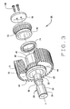
Figure 1 is a perspective view, partially broken away and in section, of an epicyclic gear system constructed in accordance with and embodying the present invention:-
Figure 2 is a sectional view of the epicyclic gear system taken along line 2-2 ofFigure 1 ; -
Figure 3 is an exploded perspective view of one of the flexpin assemblies for the epicyclic gear system; -
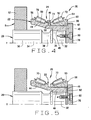
Figure 4 is a partial sectional view of the flexpin assembly ofFigure 3 ; -
Figure 5 is a partial sectional view of a variation of the flexpin assembly ofFigures 3 and4 ; -
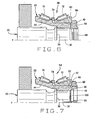
Figure 6 is a partial sectional view of an alternative flexpin assembly; and -
Figure 7 is a partial sectional view of another alternative flexpin assembly.
-
- Referring now to the drawings; an epicyclic gear system A (
Fig. 1 ) that is organized about a central axis X includes asun gear 2, aring gear 4, andplanet pinions 6 located between and engaged with thesun gear 2 andring gear 4. In addition, the gear system A includes acarrier 8 that establishes offset axes Y about which the planet pinions 6 rotate, and those axes Y should lie parallel to the central axis X. Any one of thesun gear 2 or thering gear 4 or thecarrier 8 may remain fixed against rotation, while the other two rotate, torque being applied to one and delivered from the other. The gear system A that is illustrated, can serve as a speed increaser, in which event torque is applied to thecarrier 8 and delivered from thesun gear 2, while thering gear 4 remains fixed. It is well suited use in a wind turbine between the wind-driven rotor and the electrical generator of the wind turbine. To this end; thecarrier 8 has an end member in the form of awall 12 to which torque is applied, while thesun gear 2 has anoutput shaft 14 coupled to it. - In addition to the
wall 12, thecarrier 8 has flexpins 20 (Figs. 2 &3 ) that project from and indeed are cantilevered from theend wall 12, oneflexpin 20 for eachplanet pinion 6. Eachflexpin 20 at its end remote from thecarrier wall 12 is fitted with a sleeve 22 (Figs. 2 - 4 ) that extends back over theflexpin 20 towards thecarrier wall 12, yet is spaced radially fromflexpin 20 except at the remote end of theflexpin 20 where thesleeve 22 fits firmly and securely around theflexpin 20. In effect, thesleeve 22 is cantilevered from the remote end of theflexpin 20 -- creating a double cantilever so to speak. Thesleeve 22 supports a bearing 24 (Fig. 2 ), and thebearing 24 in turn supports one of theplanet pinions 6. Theflexpin 20, thesleeve 22 that it supports, and the bearing 24 --or at least a part of it-- that enables thepinion 6 to rotate on thesleeve 22, with or without theplanet pinion 6, constitute aflexpin assembly 26. - The double cantilever formed by the
flexpin 20 and thesleeve 22 that extends back over theflexpin 20 enables the offset axis Y about which theplanet pinion 6 rotates to remain parallel to the central axis X. This in turn insures a good mesh between theplanet pinion 6 and the sun andring gears carrier wall 12, eachflexpin 20 deflects near thewall 12 generally circumferentially along the pitch circle defined by the several axes Y, so that the remote end of theflexpin 20 trails the end that is anchored in thewall 12. Thepin 20, however, possesses enough flexibility at its remote end to flex in the opposite direction circumferentially so as to enable thesleeve 22 to remain parallel to the central axis X. Contrast this with a straddle-type carrier with two walls, each pin affixed at both of its ends in the two walls. That type of carrier deforms under the torque transmitted through it, and the pins skew with regard to the central axis of the gear system. - The
flexpin 20 for eachplanet pinion 6 has (Figs. 2 &3 ) abase 30 at which it is fitted to thewall 12 of thecarrier 8 and ahead 32 at which thesleeve 22 is fitted to theflexpin 20. Between thebase 30 and thehead 32 theflexpin 20 has ashank 34. The diameter of theshank 34 may exceed that of thehead 32, and the two merge at an abutment such as ashoulder 36. Thesleeve 22 extends over, yet is spaced radially from, theshank 34. To enhance the flexibility of theflexpin 20, itsshank 34 may contain agroove 38 near theshoulder 36. - The
flexpin 20 is attached at itsbase 30 to thecarrier wall 12 in any one of several ways. In this regard, thebase 30 may have a cylindrical exterior surface (Fig. 2 ), while thewall 12 opposite eachplanet pinion 6 has a cylindrical bore, the diameter of which is slightly smaller than the diameter of the surface, at least initially. Thebase 30 is pressed into the bore so that an interference fit exists between its cylindrical surface and the surface of the bore. In the alternative, thebase 30 may have a tapered surface and beyond that surface a thread that projects beyond thecarrier wall 12 where it is engaged by a nut as inUS 7,056,259 . Also, thebase 30 may have a flange that is secured to thecarrier wall 12 with cap screws as inWO 2007/016336 . - The
sleeve 22 extends over and is supported on thehead 32 of theflexpin 20. Here thesleeve 22 is provided with a mountingsection 40 that fits over thehead 32 with an interference fit and abuts theshoulder 36. The mountingsection 40 has (Figs. 2 &3 ) acylindrical bearing seat 42 that is presented outwardly away from the axis Y of theflexpin 20. The remainder of thesleeve 22 takes the form of an integratedinner race 44 that extends over theshank 34, yet is spaced outwardly from theshank 34 and terminates short of thecarrier wall 12. The mountingsection 40 andintegrated race 44 merge generally midway between the ends of thesleeve 22, and in this region thesleeve 22 has ashoulder 46. At the opposite end of the mountingsection 40, thesleeve 22 has anend face 48 that is perpendicular to the axis Y. - The
bearing 24 includes (Fig. 2 ) taperedouter raceways planet pinion 6 that is supported on theflexpin 20 and itssleeve 22, but in any event are carried by theplanet pinion 6. Theraceways flexpin 20, taper downwardly toward each other, so as to have their least diameters where they are closest. Theintegrated race 44, to a measure, forms part of the bearing 24 in that it has a taperedinner raceway 54 and athrust rib 56 at the large end of theraceway 54. Theraceway 54, which is integral to thesleeve 22, is presented outwardly toward theraceway 50 on thepinion 6 and tapers in the same direction. Complementing the integratedinner race 44 and likewise forming part of thebearing 24 is a separateinner race 60 that fits over the bearingseat 42 of thesleeve 22 with an interference fit. It has a taperedraceway 62 that is presented outwardly toward the otherouter raceway 52 in theplanet pinion 6 and tapers in the same direction as theraceway 52. Therace 60 also has athrust rib 64 at the large end of itsraceway 62. Therib 64 extends axially beyond the end of thehead 32 on theflexpin 20 and terminates at aback face 66. At its opposite end therace 60 has afront face 68 that is presented toward theshoulder 46 on thesleeve 22. Completing thebearing 24 are taperedrollers 70 organized in a row around theintegrated race 44 and moretapered rollers 72 organized in another row around theseparate race 60. Therollers 70 contact theouter raceway 50 and theinner raceway 54. Moreover, therollers 70 are on apex, meaning the conical envelopes in which their tapered side faces lie and likewise the conical envelopes in which theraceways rollers 72 contact theouter raceway 52 andinner raceway 62 of theseparate race 60 and are likewise on apex. - The bearing 24 should be initially set such that it operates in a condition of light preload, that is to say with no clearances, either axial or radial, between the
rollers 70 and theirraceways rollers 72 and theraceways bearing 24, the bearing 24 between theshoulder 46 on thesleeve 22 and thefront face 68 of theseparate race 60 is fitted with aspacer 74 that establishes a prescribed distance between theinner raceways - The
sleeve 22 and theseparate race 60 are captured in a fixed axial position on theflexpin 20 by an end plate 78 (Fig. 2 ) which covers the end face of thepin 20 and bears against theback face 66 of theseparate race 60. Although a slight gap exists between the end face of theflexpin 20 and theplate 78, theplate 78 is held firmly against theback face 66 of therace 60 bycap screws 80 that pass through theplate 78 and thread into theflexpin 20. Actually, the clamping force exerted by the cap screws 80 on theend plate 78 is transmitted through therace 60 to thespacer 74 which in turn transmits the force to thesleeve 22, so that the force likewise holds the mountingsection 40 of thesleeve 22 against theshoulder 36 of theflexpin 20. - When the gear system A transmits torque, under most circumstances the planet pinions 6 will rotate between the
sun gear 2 and thering gear 4 with which they are engaged at their teeth. The bearing 24 for eachflexpin assembly 26 confines eachplanet pinion 6 both axially and radially with respect to itssleeve 22 andflexpin 20, yet enables it to rotate with minimal friction about the axis Y for theflexpin assembly 26. The torque, if its magnitude is great enough, will deflect theflexpin 20 where it emerges from thecarrier wall 12, with that deflection being circumferentially with respect to the central axis X. But theflexpin 20 flexes in the opposite direction, again circumferentially relative to the axis X, at itsgroove 38 or otherwise near the mountingsection 40. As a consequence, the axis of thesleeve 22, which is the axis Y, remains parallel to the central axis X, and a good mesh exists between the teeth of theplanet pinion 6 and the teeth of thesun gear 2 andring gear 4. - In lieu of controlling the settings of the
bearing 24 for eachflexpin assembly 26 with aspacer 74, it may be controlled with a shim 82 (Fig. 5 ) located between the end of themount 40 for thesleeve 22 and theend plate 78. The force required to maintain the mountingsection 40 of thesleeve 22 against theshoulder 36 of theflexpin 20 is again exerted by the cap screws 80, but theshim 82 transmits it from theend plate 78 to the mountingsection 40 of thesleeve 22. The thickness of theshim 82 does not affect the force, but it does control the axial position of theseparate race 60 and hence the setting for thebearing 24. - An alternative flexpin assembly 86 (
Fig. 6 ) closely resembles theassembly 26. However, itsflexpin 20 has a threadedextension 88 formed integral with and projecting axially from itshead 32. Theextension 88 accommodates anut 90 which threads over it and bears against theback face 66 of theseparate race 60, securing therace 60 on thesleeve 22 and thesleeve 22 on theflexpin 20. - The
alternative flexpin assembly 86 has aspacer 74 that establishes the setting for thebearing 24, but the setting may be controlled with ashim 82 located between thenut 90 and theend face 48 of themount 40 for thesleeve 22. - Another alternative flexpin assembly 94 (
Fig. 7 ) likewise resembles theflexpin assembly 26, but differs essentially in the configuration of thesleeve 22. Thatsleeve 22 has anannular rib 96 projecting from itsend face 48, leaving theend face 48 with a lesser area located immediately outwardly from the end of thehead 32 on theflexpin 20. Therib 96 has an external thread that is engaged by anut 98 that is turned down against theback face 66 of theseparate race 60. The modifiedsleeve 22 is secured to thehead 32 of theflexpin 20 by anend plate 100 which in turn is secured to theflexpin 20 with cap screws 80. The force exerted on theplate 100 by thescrews 80 is transmitted to the mountingsection 40 of thesleeve 22 at theend face 48 of thesleeve 22 and serves to clamp the mountingsection 40 between theshoulder 36 of theflexpin 20 and theplate 100. - The setting for the bearing 24 of the
alternative flexpin assembly 94 may be established with aspacer 74, in which event theseparate race 60 is clamped betweenspacer 74 and thenut 98. Or thespacer 74 may be eliminated and the setting controlled by advancing thenut 98 until the position of therace 60 on the bearingseat 42 provides the bearing 24 with the desired setting. - Any one of the
flexpin assemblies pin 20 from thecarrier wall 12. Moreover, the setting for itsbearing 24 is controlled by the position of theseparate race 60 on the bearingseat 42 of thesleeve 22, and varying the axial position of therace 60 is a relatively simple procedure. Certainly, it is less complicated than the procedure required for a fully integrated flexpin assembly in which both inner raceways form surfaces of the sleeve and the sleeve has a separate rib ring. The ease with which theflexpin assemblies bearings 24 may be adjusted make theassemblies spacer 74 orshim 82 for thebearing 24 or otherwise changing the position of theseparate race 60 on the bearingseat 42. - The bearing 24 need not be a tapered roller bearing. It could take the form of some other type of bearing having one raceway on a race integrated into the
sleeve 22 and another separate race located on a bearingseat 42 provided by thesleeve 22. Thebearing 24 may be an angular contact ball bearing organized in two rows, a spherical roller bearing, or even a cylindrical roller bearing with rollers in one or multiple rows. Theouter raceways planet pinion 6 or where thebearing 24 takes some other form they may be on a separate race or races appropriate for that type of bearing. Theend plate head 32 of theflexpin 20 and a nut threaded over the stud. The end member of thecarrier 8 need not take the form of a wall, but may be some other configuration that is suitable for a carrier, such as a spider-shape. Furthermore, thesun gear 2 andring gear 4 as well as thepinions 6 may have helical teeth, in which event a deflection inhibitor may be provided on thesleeve 22 or between thesleeve 22 and thepin 20 to prevent thesleeve 22 from deflecting radially with respect to the central axis X under the coupled created by the helical teeth when torque is transmitted, all as set forth inWO 2009/152306 . Be that as it may, thesleeve 22 is still essentially spaced from thepin 20 remote from thehead 32 on thepin 20.
Claims (13)
- A flexpin assembly for an epicyclic gear system (A), said flexpin assembly having an axis (Y) and comprising:a flexpin (20) having a base (30) and a head (32) remote from the base;a sleeve (22) located around the flexpin (20) and attached firmly to the flexpin at the head (32) of the flexpin, but otherwise being essentially spaced radially from the flexpin, the sleeve (22) having an integral race (44) provided with an inner raceway (54) that is presented outwardly away from the axis (Y), characterised in that the sleeve (22) has a bearing seat (42) next to the integral race, and in thatan initially separate race (60) is provided on the bearing seat (42) of the sleeve (22) and has an inner raceway (62) that is also presented outwardly, away from the axis (Y), rolling elements (70, 72) being arranged along the inner raceways (54, 62).
- A flexpin assembly according to claim 1 wherein the sleeve (22) fits over the head (32) of the flexpin (20).
- A flexpin assembly according to claim 2 wherein the flexpin (20) has an abutment (36) at its head, and the sleeve (22) has a mounting section (40) that fits over the head (32) and against the abutment (36); and further comprising means for urging the mounting section against the abutment.
- A flexpin assembly according to claim 3 wherein the bearing seat (42) is on the mounting section (40).
- A flexpin assembly according to claim 3 wherein the mounting section (40) has an end face (48) that is presented axially away from the abutment (36); and wherein the means for urging the mounting section against the abutment includes a plate (78, 100) that is located opposite the end face (48) of the mounting section (40).
- A flexpin assembly according to claim 5 wherein the plate (78, 100) exerts an axially directed force on the mounting section (40) of the sleeve (22).
- A flexpin assembly according to claim 6 wherein the separate race (60) has a back face (66), and the plate (78) bears against the back face (66).
- A flexpin assembly according to claim 7 wherein the plate (78) exerts an axially directed force on the separate race (60), and that force is transmitted through the separate race (60) to the sleeve (22) and urges the mounting section (40) of the sleeve against the abutment (36) on the flexpin (20).
- A flexpin assembly according to claim 6 wherein the sleeve (22) has a threaded rib (96) that projects axially from its mounting section (40); and wherein a nut (98) threads over the rib (96) and serves to position the separate race (60) axially on the bearing seat (42) of the mounting section.
- A flexpin assembly according to claim 3 wherein the means for urging the mounting section (40) against the abutment (36) comprises a threaded extension (88) projecting axially from the head (32) of the flexpin (20) and a nut (90) threaded over the extension (88) and located opposite the separate race (60) and the mounting section (40) of the sleeve.
- A flexpin assembly according to claim 3 and further comprising a planet pinion (6) located around the sleeve (22) and carrying outer raceways (50, 52) that are presented opposite the inner raceways (54, 62) and contact the rolling elements (70, 72), the outer raceways (50, 52), the integral race, the initially separate race (60) and the rolling elements (70, 72) forming a bearing (24).
- An epicyclic gear system comprising:a sun gear (2);a ring gear (4) surrounding the sun gear (2);a carrier (8) including an end member (12) and flexpin assemblies according to claim 11, the planet pinions (6) of the flexpin assemblies being located between and being engaged with the sun and ring gears (2, 4), the flexpins (20) of the flexpin assemblies being fitted to the end member (12).
- A flexpin assembly according to claim 1 wherein the inner raceways (54, 62) on the integral race (44) and on the initially separate race (60) are inclined with respect to the axis (Y), with the raceway (54) on the integral race (44) being inclined in one direction and the raceway (62) on the initially separate race (60) being inclined in the opposite direction.
Applications Claiming Priority (2)
| Application Number | Priority Date | Filing Date | Title |
|---|---|---|---|
| US17197209P | 2009-04-23 | 2009-04-23 | |
| PCT/US2010/031843 WO2010123964A1 (en) | 2009-04-23 | 2010-04-21 | Epicyclic gear system with semi-integrated flexpin assemblies |
Publications (2)
| Publication Number | Publication Date |
|---|---|
| EP2422111A1 EP2422111A1 (en) | 2012-02-29 |
| EP2422111B1 true EP2422111B1 (en) | 2013-10-16 |
Family
ID=42289492
Family Applications (1)
| Application Number | Title | Priority Date | Filing Date |
|---|---|---|---|
| EP10714550.0A Active EP2422111B1 (en) | 2009-04-23 | 2010-04-21 | Epicyclic gear system with semi-integrated flexpin assemblies |
Country Status (7)
| Country | Link |
|---|---|
| US (1) | US8920284B2 (en) |
| EP (1) | EP2422111B1 (en) |
| KR (1) | KR20120004404A (en) |
| CN (1) | CN102422052B (en) |
| DK (1) | DK2422111T3 (en) |
| ES (1) | ES2437128T3 (en) |
| WO (1) | WO2010123964A1 (en) |
Families Citing this family (37)
| Publication number | Priority date | Publication date | Assignee | Title |
|---|---|---|---|---|
| DK2283250T3 (en) * | 2008-04-30 | 2012-11-26 | Timken Co | Epicyclic gear system with flex pins |
| DE102009032294A1 (en) * | 2009-07-09 | 2011-01-13 | Aktiebolaget Skf | bearing arrangement |
| US8536726B2 (en) * | 2010-09-17 | 2013-09-17 | Vestas Wind Systems A/S | Electrical machines, wind turbines, and methods for operating an electrical machine |
| US8777802B2 (en) * | 2011-04-29 | 2014-07-15 | General Electric Company | Gear system and method for using same |
| DE102011079992A1 (en) * | 2011-07-28 | 2013-01-31 | Schaeffler Technologies AG & Co. KG | Gear device for a gear train |
| US8550955B2 (en) * | 2011-08-16 | 2013-10-08 | General Electric Company | Pin for planetary gear system |
| US9468715B2 (en) | 2012-09-17 | 2016-10-18 | Micrel Medical Devices S.A. | Infusion rotary peristaltic pump |
| US9254713B2 (en) | 2013-03-15 | 2016-02-09 | American Axle & Manufacturing, Inc. | Axle assembly with inboard axle shaft bearings that support a differential mechanism |
| US9157515B2 (en) * | 2013-03-15 | 2015-10-13 | American Axle & Manufacturing, Inc. | Axle assembly |
| WO2014143867A1 (en) * | 2013-03-15 | 2014-09-18 | Springs Window Fashions, Llc | Window covering motorized lift and control system motor and operation |
| US9103427B2 (en) | 2013-03-15 | 2015-08-11 | American Axle & Manufacturing, Inc. | Axle assembly |
| US9028358B2 (en) | 2013-03-15 | 2015-05-12 | American Axle & Manufacturing, Inc. | Disconnecting axle assembly |
| DE102013214869B4 (en) * | 2013-07-30 | 2019-01-31 | Schaeffler Technologies AG & Co. KG | Unsymmetric tapered roller bearing for supporting a gear on a gear shaft |
| DE102013226520A1 (en) * | 2013-12-18 | 2015-06-18 | Zf Friedrichshafen Ag | Axial fixation of a planetary bearing |
| BR102015011976B1 (en) * | 2014-06-03 | 2023-12-12 | American Axle & Manufacturing, Inc | SHAFT ASSEMBLY HAVING AN ANGULAR CONTACT BRACKET THAT SUPPORTS A RING GEAR FOR ROTATING IN A SHAFT HOUSING |
| CN104214212A (en) * | 2014-08-21 | 2014-12-17 | 沈阳罕王精密轴承有限公司 | Double-row conical and cylindrical roller combination bearing having gears on outer ring |
| DE102014222275A1 (en) * | 2014-10-31 | 2016-05-04 | Aktiebolaget Skf | Bearing arrangement for a planetary gear |
| DE102014222281A1 (en) * | 2014-10-31 | 2016-05-04 | Aktiebolaget Skf | Bearing arrangement for a planetary gear |
| DE102014225417A1 (en) * | 2014-12-10 | 2016-06-16 | Zf Friedrichshafen Ag | Articulated planetary shaft |
| DE102015214832A1 (en) | 2015-08-04 | 2017-02-09 | Schaeffler Technologies AG & Co. KG | planetary drive |
| US10267401B2 (en) | 2015-11-25 | 2019-04-23 | American Axle & Manufacturing, Inc. | Axle assembly |
| CN108700183B (en) | 2016-03-25 | 2022-05-06 | 美国轮轴制造公司 | Disconnected axle assembly |
| CN109196247B (en) * | 2016-05-27 | 2021-09-21 | 刘刚 | Multi-wheel torquer |
| US10408304B2 (en) * | 2017-02-07 | 2019-09-10 | General Electric Company | Gears having reduced roller element stresses and methods of manufacturing such gears |
| US10113631B2 (en) | 2017-02-08 | 2018-10-30 | American Axle & Manufacturing, Inc. | Axle assembly having ring gear with unitarily and integrally formed portion of a bearing race |
| FR3071026B1 (en) * | 2017-09-12 | 2020-02-28 | Safran Transmission Systems | PIVOT FOR SMOOTH BEARING AND GEAR TRAIN |
| DE102017219614A1 (en) * | 2017-11-06 | 2019-05-09 | Zf Friedrichshafen Ag | Planet carrier with flexible bolts |
| US10495210B2 (en) | 2017-11-09 | 2019-12-03 | General Electric Company | Integral ring gear and torque arm for a wind turbine gearbox |
| US10330174B2 (en) | 2017-11-09 | 2019-06-25 | General Electric Company | Gear assembly for a wind turbine gearbox having a flexible pin shaft and carrier |
| US10682705B2 (en) | 2017-11-09 | 2020-06-16 | General Electric Company | Gear assembly for a wind turbine gearbox having a flexible pin shaft and carrier |
| CN112313022A (en) | 2018-06-25 | 2021-02-02 | 通用电气公司 | Journal bearing for additive manufacturing of wind turbine gearbox |
| US10927937B2 (en) | 2018-09-06 | 2021-02-23 | American Axle & Manufacturing, Inc. | Modular disconnecting drive module with torque vectoring augmentation |
| US10704663B2 (en) | 2018-09-06 | 2020-07-07 | American Axle & Manufacturing, Inc. | Modular disconnecting drive module with torque vectoring augmentation |
| DE102019207100A1 (en) * | 2019-05-16 | 2020-11-19 | Zf Friedrichshafen Ag | Planet carrier with flexible bolts and stiffening rib |
| US11105395B2 (en) * | 2019-10-23 | 2021-08-31 | Pratt & Whitney Canada Corp. | Planetary gear assembly and method of operating same |
| US11111014B2 (en) * | 2019-10-23 | 2021-09-07 | Textron Innovations Inc. | Integral flexured carriers for aircraft planetary gear systems |
| US11773963B2 (en) * | 2020-06-29 | 2023-10-03 | General Electric Company | Wind turbine gearbox carrier with integrated pin shafts and method of manufacturing same |
Family Cites Families (9)
| Publication number | Priority date | Publication date | Assignee | Title |
|---|---|---|---|---|
| US1843463A (en) * | 1930-07-24 | 1932-02-02 | Skayef Ball Bearing Company | Separation of taper-fitted parts |
| US2666676A (en) * | 1952-03-06 | 1954-01-19 | Sterling Steel Casting Co | Idler wheel unit |
| JPH01178220U (en) * | 1988-06-07 | 1989-12-20 | ||
| JP3181099B2 (en) * | 1992-06-23 | 2001-07-03 | 三菱重工業株式会社 | Planetary gear set |
| US6994651B2 (en) * | 2003-10-07 | 2006-02-07 | The Timken Company | Epicyclic gear system |
| EP1745221B1 (en) * | 2004-05-07 | 2008-10-15 | The Timken Company | Locating bearing assembly for wind turbine gearbox shaft |
| GB2413836B (en) * | 2005-07-08 | 2006-04-12 | Orbital 2 Ltd | A gear mounting |
| DE102006013079B3 (en) * | 2006-03-22 | 2007-09-06 | Ab Skf | Machine part rotating around shaft on tapered roller bearing, designed as planet wheel with integrated bearing |
| CN101398067B (en) * | 2008-02-20 | 2013-02-20 | 陈广强 | Vehicle planetary stepless transmission |
-
2010
- 2010-04-21 ES ES10714550.0T patent/ES2437128T3/en active Active
- 2010-04-21 EP EP10714550.0A patent/EP2422111B1/en active Active
- 2010-04-21 DK DK10714550.0T patent/DK2422111T3/en active
- 2010-04-21 US US13/265,769 patent/US8920284B2/en active Active
- 2010-04-21 WO PCT/US2010/031843 patent/WO2010123964A1/en active Application Filing
- 2010-04-21 CN CN201080017893.0A patent/CN102422052B/en not_active Expired - Fee Related
- 2010-04-21 KR KR1020117020720A patent/KR20120004404A/en not_active Application Discontinuation
Also Published As
| Publication number | Publication date |
|---|---|
| WO2010123964A1 (en) | 2010-10-28 |
| US20120040797A1 (en) | 2012-02-16 |
| CN102422052B (en) | 2014-09-24 |
| CN102422052A (en) | 2012-04-18 |
| DK2422111T3 (en) | 2013-12-09 |
| ES2437128T3 (en) | 2014-01-09 |
| US8920284B2 (en) | 2014-12-30 |
| KR20120004404A (en) | 2012-01-12 |
| EP2422111A1 (en) | 2012-02-29 |
Similar Documents
| Publication | Publication Date | Title |
|---|---|---|
| EP2422111B1 (en) | Epicyclic gear system with semi-integrated flexpin assemblies | |
| EP2283250B1 (en) | Epicyclic gear system with flexpins | |
| EP1910708B1 (en) | Epicyclic gear system with flexpins | |
| US8376902B2 (en) | Epicyclic gear system with flexpins and helical gearing | |
| US8222759B2 (en) | Rotor bearing for a wind turbine | |
| EP1639276B1 (en) | Transmission containing helical gearing and bearing arrangement therefor | |
| US7056259B2 (en) | Epicyclic gear system | |
| EP1252442B1 (en) | Gear unit | |
| US8608444B2 (en) | Single-bearing structure and wind power plant having the single-bearing structure | |
| CN109973336B (en) | Wind power plant with a drive train | |
| CN107288825B (en) | Wind power plant with a drive train | |
| US11384829B2 (en) | Planetary transmission, powertrain and wind turbine |
Legal Events
| Date | Code | Title | Description |
|---|---|---|---|
| PUAI | Public reference made under article 153(3) epc to a published international application that has entered the european phase |
Free format text: ORIGINAL CODE: 0009012 |
|
| 17P | Request for examination filed |
Effective date: 20111103 |
|
| AK | Designated contracting states |
Kind code of ref document: A1 Designated state(s): AT BE BG CH CY CZ DE DK EE ES FI FR GB GR HR HU IE IS IT LI LT LU LV MC MK MT NL NO PL PT RO SE SI SK SM TR |
|
| DAX | Request for extension of the european patent (deleted) | ||
| GRAP | Despatch of communication of intention to grant a patent |
Free format text: ORIGINAL CODE: EPIDOSNIGR1 |
|
| INTG | Intention to grant announced |
Effective date: 20130705 |
|
| GRAS | Grant fee paid |
Free format text: ORIGINAL CODE: EPIDOSNIGR3 |
|
| GRAA | (expected) grant |
Free format text: ORIGINAL CODE: 0009210 |
|
| AK | Designated contracting states |
Kind code of ref document: B1 Designated state(s): AT BE BG CH CY CZ DE DK EE ES FI FR GB GR HR HU IE IS IT LI LT LU LV MC MK MT NL NO PL PT RO SE SI SK SM TR |
|
| REG | Reference to a national code |
Ref country code: GB Ref legal event code: FG4D |
|
| REG | Reference to a national code |
Ref country code: CH Ref legal event code: EP |
|
| REG | Reference to a national code |
Ref country code: IE Ref legal event code: FG4D |
|
| REG | Reference to a national code |
Ref country code: AT Ref legal event code: REF Ref document number: 636660 Country of ref document: AT Kind code of ref document: T Effective date: 20131115 |
|
| REG | Reference to a national code |
Ref country code: DK Ref legal event code: T3 Effective date: 20131204 |
|
| REG | Reference to a national code |
Ref country code: DE Ref legal event code: R096 Ref document number: 602010010966 Country of ref document: DE Effective date: 20131212 |
|
| REG | Reference to a national code |
Ref country code: ES Ref legal event code: FG2A Ref document number: 2437128 Country of ref document: ES Kind code of ref document: T3 Effective date: 20140109 |
|
| REG | Reference to a national code |
Ref country code: NL Ref legal event code: VDEP Effective date: 20131016 |
|
| REG | Reference to a national code |
Ref country code: AT Ref legal event code: MK05 Ref document number: 636660 Country of ref document: AT Kind code of ref document: T Effective date: 20131016 |
|
| REG | Reference to a national code |
Ref country code: LT Ref legal event code: MG4D |
|
| PG25 | Lapsed in a contracting state [announced via postgrant information from national office to epo] |
Ref country code: HR Free format text: LAPSE BECAUSE OF FAILURE TO SUBMIT A TRANSLATION OF THE DESCRIPTION OR TO PAY THE FEE WITHIN THE PRESCRIBED TIME-LIMIT Effective date: 20131016 Ref country code: NL Free format text: LAPSE BECAUSE OF FAILURE TO SUBMIT A TRANSLATION OF THE DESCRIPTION OR TO PAY THE FEE WITHIN THE PRESCRIBED TIME-LIMIT Effective date: 20131016 Ref country code: NO Free format text: LAPSE BECAUSE OF FAILURE TO SUBMIT A TRANSLATION OF THE DESCRIPTION OR TO PAY THE FEE WITHIN THE PRESCRIBED TIME-LIMIT Effective date: 20140116 Ref country code: FI Free format text: LAPSE BECAUSE OF FAILURE TO SUBMIT A TRANSLATION OF THE DESCRIPTION OR TO PAY THE FEE WITHIN THE PRESCRIBED TIME-LIMIT Effective date: 20131016 Ref country code: IS Free format text: LAPSE BECAUSE OF FAILURE TO SUBMIT A TRANSLATION OF THE DESCRIPTION OR TO PAY THE FEE WITHIN THE PRESCRIBED TIME-LIMIT Effective date: 20140216 Ref country code: SE Free format text: LAPSE BECAUSE OF FAILURE TO SUBMIT A TRANSLATION OF THE DESCRIPTION OR TO PAY THE FEE WITHIN THE PRESCRIBED TIME-LIMIT Effective date: 20131016 Ref country code: LT Free format text: LAPSE BECAUSE OF FAILURE TO SUBMIT A TRANSLATION OF THE DESCRIPTION OR TO PAY THE FEE WITHIN THE PRESCRIBED TIME-LIMIT Effective date: 20131016 Ref country code: BE Free format text: LAPSE BECAUSE OF FAILURE TO SUBMIT A TRANSLATION OF THE DESCRIPTION OR TO PAY THE FEE WITHIN THE PRESCRIBED TIME-LIMIT Effective date: 20131016 |
|
| PG25 | Lapsed in a contracting state [announced via postgrant information from national office to epo] |
Ref country code: CY Free format text: LAPSE BECAUSE OF FAILURE TO SUBMIT A TRANSLATION OF THE DESCRIPTION OR TO PAY THE FEE WITHIN THE PRESCRIBED TIME-LIMIT Effective date: 20131016 Ref country code: AT Free format text: LAPSE BECAUSE OF FAILURE TO SUBMIT A TRANSLATION OF THE DESCRIPTION OR TO PAY THE FEE WITHIN THE PRESCRIBED TIME-LIMIT Effective date: 20131016 Ref country code: LV Free format text: LAPSE BECAUSE OF FAILURE TO SUBMIT A TRANSLATION OF THE DESCRIPTION OR TO PAY THE FEE WITHIN THE PRESCRIBED TIME-LIMIT Effective date: 20131016 |
|
| PG25 | Lapsed in a contracting state [announced via postgrant information from national office to epo] |
Ref country code: PT Free format text: LAPSE BECAUSE OF FAILURE TO SUBMIT A TRANSLATION OF THE DESCRIPTION OR TO PAY THE FEE WITHIN THE PRESCRIBED TIME-LIMIT Effective date: 20140217 |
|
| REG | Reference to a national code |
Ref country code: DE Ref legal event code: R097 Ref document number: 602010010966 Country of ref document: DE |
|
| PG25 | Lapsed in a contracting state [announced via postgrant information from national office to epo] |
Ref country code: EE Free format text: LAPSE BECAUSE OF FAILURE TO SUBMIT A TRANSLATION OF THE DESCRIPTION OR TO PAY THE FEE WITHIN THE PRESCRIBED TIME-LIMIT Effective date: 20131016 |
|
| PLBE | No opposition filed within time limit |
Free format text: ORIGINAL CODE: 0009261 |
|
| STAA | Information on the status of an ep patent application or granted ep patent |
Free format text: STATUS: NO OPPOSITION FILED WITHIN TIME LIMIT |
|
| PG25 | Lapsed in a contracting state [announced via postgrant information from national office to epo] |
Ref country code: RO Free format text: LAPSE BECAUSE OF FAILURE TO SUBMIT A TRANSLATION OF THE DESCRIPTION OR TO PAY THE FEE WITHIN THE PRESCRIBED TIME-LIMIT Effective date: 20131016 Ref country code: SK Free format text: LAPSE BECAUSE OF FAILURE TO SUBMIT A TRANSLATION OF THE DESCRIPTION OR TO PAY THE FEE WITHIN THE PRESCRIBED TIME-LIMIT Effective date: 20131016 Ref country code: IT Free format text: LAPSE BECAUSE OF FAILURE TO SUBMIT A TRANSLATION OF THE DESCRIPTION OR TO PAY THE FEE WITHIN THE PRESCRIBED TIME-LIMIT Effective date: 20131016 Ref country code: CZ Free format text: LAPSE BECAUSE OF FAILURE TO SUBMIT A TRANSLATION OF THE DESCRIPTION OR TO PAY THE FEE WITHIN THE PRESCRIBED TIME-LIMIT Effective date: 20131016 Ref country code: PL Free format text: LAPSE BECAUSE OF FAILURE TO SUBMIT A TRANSLATION OF THE DESCRIPTION OR TO PAY THE FEE WITHIN THE PRESCRIBED TIME-LIMIT Effective date: 20131016 |
|
| 26N | No opposition filed |
Effective date: 20140717 |
|
| REG | Reference to a national code |
Ref country code: DE Ref legal event code: R097 Ref document number: 602010010966 Country of ref document: DE Effective date: 20140717 |
|
| PG25 | Lapsed in a contracting state [announced via postgrant information from national office to epo] |
Ref country code: MC Free format text: LAPSE BECAUSE OF FAILURE TO SUBMIT A TRANSLATION OF THE DESCRIPTION OR TO PAY THE FEE WITHIN THE PRESCRIBED TIME-LIMIT Effective date: 20131016 Ref country code: LU Free format text: LAPSE BECAUSE OF FAILURE TO SUBMIT A TRANSLATION OF THE DESCRIPTION OR TO PAY THE FEE WITHIN THE PRESCRIBED TIME-LIMIT Effective date: 20140421 |
|
| REG | Reference to a national code |
Ref country code: CH Ref legal event code: PL |
|
| REG | Reference to a national code |
Ref country code: FR Ref legal event code: ST Effective date: 20141231 |
|
| REG | Reference to a national code |
Ref country code: IE Ref legal event code: MM4A |
|
| PG25 | Lapsed in a contracting state [announced via postgrant information from national office to epo] |
Ref country code: LI Free format text: LAPSE BECAUSE OF NON-PAYMENT OF DUE FEES Effective date: 20140430 Ref country code: CH Free format text: LAPSE BECAUSE OF NON-PAYMENT OF DUE FEES Effective date: 20140430 |
|
| PG25 | Lapsed in a contracting state [announced via postgrant information from national office to epo] |
Ref country code: FR Free format text: LAPSE BECAUSE OF NON-PAYMENT OF DUE FEES Effective date: 20140430 Ref country code: SI Free format text: LAPSE BECAUSE OF FAILURE TO SUBMIT A TRANSLATION OF THE DESCRIPTION OR TO PAY THE FEE WITHIN THE PRESCRIBED TIME-LIMIT Effective date: 20131016 |
|
| PG25 | Lapsed in a contracting state [announced via postgrant information from national office to epo] |
Ref country code: IE Free format text: LAPSE BECAUSE OF NON-PAYMENT OF DUE FEES Effective date: 20140421 |
|
| PG25 | Lapsed in a contracting state [announced via postgrant information from national office to epo] |
Ref country code: MT Free format text: LAPSE BECAUSE OF FAILURE TO SUBMIT A TRANSLATION OF THE DESCRIPTION OR TO PAY THE FEE WITHIN THE PRESCRIBED TIME-LIMIT Effective date: 20131016 |
|
| PG25 | Lapsed in a contracting state [announced via postgrant information from national office to epo] |
Ref country code: SM Free format text: LAPSE BECAUSE OF FAILURE TO SUBMIT A TRANSLATION OF THE DESCRIPTION OR TO PAY THE FEE WITHIN THE PRESCRIBED TIME-LIMIT Effective date: 20131016 |
|
| PG25 | Lapsed in a contracting state [announced via postgrant information from national office to epo] |
Ref country code: GR Free format text: LAPSE BECAUSE OF FAILURE TO SUBMIT A TRANSLATION OF THE DESCRIPTION OR TO PAY THE FEE WITHIN THE PRESCRIBED TIME-LIMIT Effective date: 20140117 Ref country code: BG Free format text: LAPSE BECAUSE OF FAILURE TO SUBMIT A TRANSLATION OF THE DESCRIPTION OR TO PAY THE FEE WITHIN THE PRESCRIBED TIME-LIMIT Effective date: 20131016 |
|
| PG25 | Lapsed in a contracting state [announced via postgrant information from national office to epo] |
Ref country code: TR Free format text: LAPSE BECAUSE OF FAILURE TO SUBMIT A TRANSLATION OF THE DESCRIPTION OR TO PAY THE FEE WITHIN THE PRESCRIBED TIME-LIMIT Effective date: 20131016 Ref country code: HU Free format text: LAPSE BECAUSE OF FAILURE TO SUBMIT A TRANSLATION OF THE DESCRIPTION OR TO PAY THE FEE WITHIN THE PRESCRIBED TIME-LIMIT; INVALID AB INITIO Effective date: 20100421 |
|
| PG25 | Lapsed in a contracting state [announced via postgrant information from national office to epo] |
Ref country code: MK Free format text: LAPSE BECAUSE OF FAILURE TO SUBMIT A TRANSLATION OF THE DESCRIPTION OR TO PAY THE FEE WITHIN THE PRESCRIBED TIME-LIMIT Effective date: 20131016 |
|
| P01 | Opt-out of the competence of the unified patent court (upc) registered |
Effective date: 20230613 |
|
| PGFP | Annual fee paid to national office [announced via postgrant information from national office to epo] |
Ref country code: ES Payment date: 20230627 Year of fee payment: 14 Ref country code: DK Payment date: 20230421 Year of fee payment: 14 Ref country code: DE Payment date: 20230420 Year of fee payment: 14 |
|
| PGFP | Annual fee paid to national office [announced via postgrant information from national office to epo] |
Ref country code: GB Payment date: 20230419 Year of fee payment: 14 |