EP2421775B1 - Compound sprocket for conveyor belt - Google Patents
Compound sprocket for conveyor belt Download PDFInfo
- Publication number
- EP2421775B1 EP2421775B1 EP10767416.0A EP10767416A EP2421775B1 EP 2421775 B1 EP2421775 B1 EP 2421775B1 EP 10767416 A EP10767416 A EP 10767416A EP 2421775 B1 EP2421775 B1 EP 2421775B1
- Authority
- EP
- European Patent Office
- Prior art keywords
- sprocket
- compound
- sprocket element
- wall portion
- conveyor belt
- Prior art date
- Legal status (The legal status is an assumption and is not a legal conclusion. Google has not performed a legal analysis and makes no representation as to the accuracy of the status listed.)
- Active
Links
Images
Classifications
-
- B—PERFORMING OPERATIONS; TRANSPORTING
- B65—CONVEYING; PACKING; STORING; HANDLING THIN OR FILAMENTARY MATERIAL
- B65G—TRANSPORT OR STORAGE DEVICES, e.g. CONVEYORS FOR LOADING OR TIPPING, SHOP CONVEYOR SYSTEMS OR PNEUMATIC TUBE CONVEYORS
- B65G23/00—Driving gear for endless conveyors; Belt- or chain-tensioning arrangements
- B65G23/02—Belt- or chain-engaging elements
- B65G23/04—Drums, rollers, or wheels
- B65G23/06—Drums, rollers, or wheels with projections engaging abutments on belts or chains, e.g. sprocket wheels
-
- F—MECHANICAL ENGINEERING; LIGHTING; HEATING; WEAPONS; BLASTING
- F16—ENGINEERING ELEMENTS AND UNITS; GENERAL MEASURES FOR PRODUCING AND MAINTAINING EFFECTIVE FUNCTIONING OF MACHINES OR INSTALLATIONS; THERMAL INSULATION IN GENERAL
- F16H—GEARING
- F16H55/00—Elements with teeth or friction surfaces for conveying motion; Worms, pulleys or sheaves for gearing mechanisms
- F16H55/02—Toothed members; Worms
- F16H55/30—Chain-wheels
-
- B—PERFORMING OPERATIONS; TRANSPORTING
- B65—CONVEYING; PACKING; STORING; HANDLING THIN OR FILAMENTARY MATERIAL
- B65G—TRANSPORT OR STORAGE DEVICES, e.g. CONVEYORS FOR LOADING OR TIPPING, SHOP CONVEYOR SYSTEMS OR PNEUMATIC TUBE CONVEYORS
- B65G2207/00—Indexing codes relating to constructional details, configuration and additional features of a handling device, e.g. Conveyors
- B65G2207/30—Modular constructions
Definitions
- the present invention is directed to a compound sprocket according to the preamble of claim 1 configured to distribute the tension load of a conveyor belt across the width thereof.
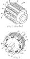
- FIG. 1 illustrates a conventional sprocket for a conveyor belt having rows 28, 30, 32, 34 of protrusions 36 machined to provide a plurality of protrusions on the cylindrical surface 40 of sprocket 26.
- Surface 40 is substantially cylindrical in relation to a central axis of rotation of sprocket 26 and the protrusions are machined to project radially from that surface.
- the protrusions 36 are machined on the surface of the drive roll or sprocket 26 so as to interfit with confronting surface openings of the conveyor belt.
- the number of protrusions selected across the sprocket width is selected to provide a substantially uniform drive across the width of the belt. Additional information concerning drive systems for conveyor belts is disclosed in U.S. Pat. Nos.
- US 6,161, 512 discloses a compound sprocket according to the preamble of claim 1, in particular the document relates to a sprocket system having an internal torsional damper which absorbs crankshaft torsional vibrations and minimizes their transfer to other components in the engine system.
- Japanese utility model JP 64-41097U discloses a sprocket system comprising springs.
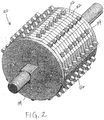
- Compound sprocket 100 includes a plurality of compound sprocket elements 102 aligned in a predetermined side-by-side configuration and held by end plates 104.
- Each compound sprocket element 102 includes an inner sprocket member 106 and an outer sprocket member 108.
- the inner sprocket member 106 is timed to a drive shaft 110 by a square bore 112, keyway, or other mounting means.
- the outer sprocket member 108 is allowed to shift around the circumference of the inner sprocket member 106 by way of a plurality of resilient connecting elements 114, as described in greater detail below.
- the compound sprocket elements 102 are arranged to form a compound sprocket 100, the width of which will vary depending on the width of the intended conveyor belt.
- the inner sprocket members 106 will be timed and compressed together by threaded rods 120 which run down the width of the compound sprocket 100 and are secured with a fastener (not shown).
- the compound sprocket 100 includes a plurality of teeth 116 for engaging a conveyor belt, as known in the art and described more fully, for example, in U.S. Patent No. 6,041,916 .
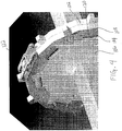
- a link 122 of one possible conveyor belt is shown in engagement with the compound sprocket element 102 in Figs. 4 and 5 .
- Link 122 forms a modular conveyor belt as described in U.S. Patent Publication No. 2002/0117382 , but other types of conveyor belts can of course also be utilized with compound sprocket 100, as will be appreciated by one skilled in the art.
- the teeth 116 are formed on the outermost periphery of the outer sprocket member 108.
- the inner sprocket member 106 also includes a plurality of radially extending protrusions 118 disposed about the periphery thereof, as shown in Fig. 3 .
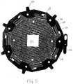
- a pocket 120 is formed in the innermost periphery of the outer sprocket member 108, preferably by machining.
- the pocket 120 receives a corresponding protrusion 118 of the inner sprocket member 106 and allows insertion of a resilient connecting element 114, such as a spring.
- the spring 114 is thus biased between the wall of the outer sprocket member 108 and the protrusion 118 so as to vary the force required to shift the outer sprocket member 108 relative to the inner sprocket member 106.
- the spring can be varied for different load situations and response times.
- the above-described compound sprocket configuration is ideally suited for a plastic construction, such as from Delrin® acetal resin.
- plastic materials which could also be used include, for example, PET, PBT, acetal, Ultem® (polyethermide), and nylon.
- the same configuration may also be used for constructing the compound sprocket from stainless steel, metal or ceramic materials, or any other desired material, as would be appreciated by one skilled in the art.
Landscapes
- Engineering & Computer Science (AREA)
- General Engineering & Computer Science (AREA)
- Mechanical Engineering (AREA)
- Gears, Cams (AREA)
- Chain Conveyers (AREA)
Description
- The present invention is directed to a compound sprocket according to the preamble of claim 1 configured to distribute the tension load of a conveyor belt across the width thereof.
-
FIG. 1 illustrates a conventional sprocket for a conveyorbelt having rows protrusions 36 machined to provide a plurality of protrusions on thecylindrical surface 40 ofsprocket 26.Surface 40 is substantially cylindrical in relation to a central axis of rotation ofsprocket 26 and the protrusions are machined to project radially from that surface. Theprotrusions 36 are machined on the surface of the drive roll or sprocket 26 so as to interfit with confronting surface openings of the conveyor belt. The number of protrusions selected across the sprocket width is selected to provide a substantially uniform drive across the width of the belt. Additional information concerning drive systems for conveyor belts is disclosed inU.S. Pat. Nos. 5,375,695 ,5,590,755 ,5,816,988 ,6,050,394 , and6,041,916 .US 6,161, 512 discloses a compound sprocket according to the preamble of claim 1, in particular the document relates to a sprocket system having an internal torsional damper which absorbs crankshaft torsional vibrations and minimizes their transfer to other components in the engine system. Japanese utility modelJP 64-41097U - While the drive rolls or sprockets discussed above are intended to provide for uniform drive across the belt width and increased widthwise dimensional drive contact, there still exists a need for improvement in this regard.
- The invention is defined as stated in claim 1.
- These and other objects, features, and advantages of the present invention will become more readily apparent to those skilled in the art upon reading the following detailed description, in conjunction with the appended drawings in which:
-
FIG. 1 is a perspective view of a conventional sprocket for driving a conveyor belt. -
FIG. 2 is a perspective view of a compound sprocket for a conveyor belt according to a preferred embodiment of the invention. -
FIG. 3 is a perspective view of the compound sprocket with the end plates removed. -
FIG. 4 is a perspective view of two compound sprocket elements being assembled into the compound sprocket shown inFIG. 2 , with a conveyor belt link positioned thereon. -
FIG. 5 is a side elevational view of the compound sprocket element shown inFIG. 4 . - A compound drive roll or sprocket for use with a conveyor belt in accordance with the present invention is shown generally in
FIGS. 2 and3 byreference numeral 100.Compound sprocket 100 includes a plurality ofcompound sprocket elements 102 aligned in a predetermined side-by-side configuration and held byend plates 104. Eachcompound sprocket element 102 includes aninner sprocket member 106 and anouter sprocket member 108. Theinner sprocket member 106 is timed to adrive shaft 110 by asquare bore 112, keyway, or other mounting means. Theouter sprocket member 108 is allowed to shift around the circumference of theinner sprocket member 106 by way of a plurality of resilient connectingelements 114, as described in greater detail below. Thecompound sprocket elements 102 are arranged to form acompound sprocket 100, the width of which will vary depending on the width of the intended conveyor belt. Theinner sprocket members 106 will be timed and compressed together by threadedrods 120 which run down the width of thecompound sprocket 100 and are secured with a fastener (not shown). - The
compound sprocket 100 includes a plurality ofteeth 116 for engaging a conveyor belt, as known in the art and described more fully, for example, inU.S. Patent No. 6,041,916 . Alink 122 of one possible conveyor belt is shown in engagement with thecompound sprocket element 102 inFigs. 4 and5 .Link 122 forms a modular conveyor belt as described inU.S. Patent Publication No. 2002/0117382 , but other types of conveyor belts can of course also be utilized withcompound sprocket 100, as will be appreciated by one skilled in the art. As shown inFig 2 , theteeth 116 are formed on the outermost periphery of theouter sprocket member 108. Theinner sprocket member 106, however, also includes a plurality of radially extendingprotrusions 118 disposed about the periphery thereof, as shown inFig. 3 . - Referring also to
Figs. 4 and5 , apocket 120 is formed in the innermost periphery of theouter sprocket member 108, preferably by machining. Thepocket 120 receives acorresponding protrusion 118 of theinner sprocket member 106 and allows insertion of a resilient connectingelement 114, such as a spring. Thespring 114 is thus biased between the wall of theouter sprocket member 108 and theprotrusion 118 so as to vary the force required to shift theouter sprocket member 108 relative to theinner sprocket member 106. The spring can be varied for different load situations and response times. When theouter sprocket members 108 shift, they allowadjacent sprocket elements 102 to receive a portion of the load. Tension in the conveyor belt will thus be more evenly loaded across the width of the conveyor belt and sharing the tension loading will increase the conveyor belt strength and life. - The above-described compound sprocket configuration is ideally suited for a plastic construction, such as from Delrin® acetal resin. Other plastic materials which could also be used include, for example, PET, PBT, acetal, Ultem® (polyethermide), and nylon. The same configuration may also be used for constructing the compound sprocket from stainless steel, metal or ceramic materials, or any other desired material, as would be appreciated by one skilled in the art.
- Although certain preferred embodiments of the present invention have been shown and described in detail, it should be understood that various changes and modifications may be made therein without departing from the scope of the appended claims.
Claims (10)
- A compound sprocket (102) comprising:at least one rotatable member including an outer sprocket element (108) and an inner sprocket element (106) symmetrically disposed relative to a central axis (110) of rotation of said at least one rotatable member;said outer sprocket element (108) including a plurality of spaced, uniformly radially-oriented teeth (116) on an outer cylindrical surface thereof for engaging a conveyor belt, said outer sprocket element (108) further including a plurality of pockets (120) formed on an inner cylindrical surface thereof;said inner sprocket element (106) having a plurality of protrusions (118) corresponding in number and position to said pockets (120) formed on said inner cylindrical surface of said outer sprocket element (108) and received therein;resilient connecting element (114) disposed in each said pocket (120) and biased between a wall of said pocket (120) of said outer sprocket element (108) and one of said protrusions (118) of said inner sprocket element (106);wherein said at least one rotatable member comprises a plurality of rotatable members (102), characterized in that said plurality of rotatable members (102) is aligned in a side-by-side configuration and secured by opposing end plates (104);wherein said pocket (120) formed on the inner cylindrical surface of said outer sprocket element (108) is defined by opposing radial wall surfaces and a circumferal wall surface extending therebetween; andwherein said circumferal wall surface includes a first wall portion having a first depth relative to the inner cylindrical surface of said outer sprocket element (108) and a second wall portion having a second depth relative to the inner cylindrical surface of said outer sprocket element (108).
- The compound sprocket (102) according to Claim 1, wherein said resilient connecting element (118) comprises a spring having a predetermined spring force.
- The compound sprocket (102) according to Claim 2, wherein the outer sprocket element (108) may shift around the circumference of the inner sprocket element (106) by way of the plurality of resilient connecting elements (114), said spring provides a varying force dependent upon load and response time whereby a force required to shift the outer sprocket element (108) relative to the inner sprocket element (106) is varied.
- The compound sprocket (102) according to Claim 1, wherein said at least one rotatable member (102) is formed from a plastic material.
- The compound sprocket (102) according to Claim 4, wherein said plastic material is selected from the group consisting of DELRIN, acetal resin, PET, PBT, acetal, polyethermide and nylon.
- The compound sprocket (102) according to Claim 1, wherein said at least one rotatable member (102) is formed from stainless steel.
- The compound sprocket (102) according to Claim 1, wherein said resilient connecting element (114) is laterally disposed in said pocket (120) and aligned with said first wall portion and said protrusion (118) of said inner sprocket element (106) is aligned with said second wall portion, said second wall portion defining an amount of play between said outer sprocket element (108) and said inner sprocket element (106).
- A conveyor system comprising;
a conveyor belt; and
a compound sprocket (102), said compound sprocket is as defined in any of claims 1-4, wherein the teeth (116) of the compound sprocket (102) are for engaging said conveyor belt. - The conveyor system according to Claim 8, wherein said conveyor belt is a modular conveyor belt.
- The conveyor system according to Claim 8, wherein said resilient connecting element (114) is laterally disposed in said pocket (120) and aligned with said first wall portion and said protrusion (118) of said inner sprocket element (106) is aligned with said second wall portion, said second wall portion defining an amount of play between said outer sprocket element (108) and said inner sprocket element (106).
Priority Applications (1)
| Application Number | Priority Date | Filing Date | Title |
|---|---|---|---|
| PL10767416T PL2421775T3 (en) | 2009-04-20 | 2010-04-20 | Compound sprocket for conveyor belt |
Applications Claiming Priority (2)
| Application Number | Priority Date | Filing Date | Title |
|---|---|---|---|
| US20292309P | 2009-04-20 | 2009-04-20 | |
| PCT/US2010/001168 WO2010123548A2 (en) | 2009-04-20 | 2010-04-20 | Compound sprocket for conveyor belt |
Publications (3)
| Publication Number | Publication Date |
|---|---|
| EP2421775A2 EP2421775A2 (en) | 2012-02-29 |
| EP2421775A4 EP2421775A4 (en) | 2016-10-12 |
| EP2421775B1 true EP2421775B1 (en) | 2018-10-17 |
Family
ID=42980177
Family Applications (1)
| Application Number | Title | Priority Date | Filing Date |
|---|---|---|---|
| EP10767416.0A Active EP2421775B1 (en) | 2009-04-20 | 2010-04-20 | Compound sprocket for conveyor belt |
Country Status (6)
| Country | Link |
|---|---|
| US (1) | US8424676B2 (en) |
| EP (1) | EP2421775B1 (en) |
| CN (1) | CN102405181B (en) |
| ES (1) | ES2698829T3 (en) |
| PL (1) | PL2421775T3 (en) |
| WO (1) | WO2010123548A2 (en) |
Families Citing this family (15)
| Publication number | Priority date | Publication date | Assignee | Title |
|---|---|---|---|---|
| USD658843S1 (en) * | 2010-09-30 | 2012-05-01 | Putsch & Company, Inc. | Transport roller for use in a washing apparatus |
| US8555836B2 (en) * | 2010-12-10 | 2013-10-15 | Delphi Technologies, Inc. | Electric drive camshaft phaser with torque rate limit at travel stops |
| US9328816B2 (en) * | 2010-12-14 | 2016-05-03 | Gates Corporation | Isolator decoupler |
| DK2687465T3 (en) * | 2012-07-17 | 2015-06-29 | Interroll Holding Ag | Conveyor roll with profile |
| WO2017147473A1 (en) | 2016-02-26 | 2017-08-31 | Provisur Technologies, Inc. | Cooking devices and methods of using the same |
| WO2017192955A1 (en) | 2016-05-05 | 2017-11-09 | Provisur Technologies, Inc. | Spiral cooking devices and methods of using the same |
| US10214360B1 (en) | 2017-08-04 | 2019-02-26 | Joy Global Underground Mining Llc | Chain conveyor and drive sprocket for same |
| USD866910S1 (en) * | 2018-09-20 | 2019-11-12 | Ammeraal Beltech Modular A/S | Sprocket for conveyor belts |
| USD866113S1 (en) * | 2018-09-20 | 2019-11-05 | Ammeraal Beltech Modular A/S | Sprocket for conveyor belts |
| USD866909S1 (en) * | 2018-09-20 | 2019-11-12 | Ammeraal Beltech Modular A/S | Sprocket for conveyor belts |
| USD866112S1 (en) * | 2018-09-20 | 2019-11-05 | Ammeraal Beltech Modular A/S | Sprocket for conveyor belts |
| WO2020123499A1 (en) * | 2018-12-13 | 2020-06-18 | Cambridge International, Inc. | Eyelink belt drive systems and methods |
| CN116323439B (en) * | 2020-11-20 | 2026-05-05 | 莱特拉姆有限责任公司 | sprocket |
| US12091256B2 (en) | 2021-09-16 | 2024-09-17 | Cambridge International, Inc. | Material buildup resistant sprocket |
| USD1086860S1 (en) * | 2023-09-29 | 2025-08-05 | Cambridge International, Inc. | Roller |
Citations (4)
| Publication number | Priority date | Publication date | Assignee | Title |
|---|---|---|---|---|
| US306267A (en) * | 1884-10-07 | Power-transmitting pulley | ||
| FR368046A (en) * | 1906-07-13 | 1906-11-15 | Louis Proust | Recovery wheel |
| JPS62114262U (en) * | 1986-01-10 | 1987-07-21 | ||
| US20030089583A1 (en) * | 2001-11-14 | 2003-05-15 | The Laitram Corporation | Compensation for shaft twist in the drive system of modular conveyor belts |
Family Cites Families (26)
| Publication number | Priority date | Publication date | Assignee | Title |
|---|---|---|---|---|
| US6161A (en) | 1849-03-10 | Island | ||
| US601990A (en) * | 1898-04-05 | Removable sprocket-rim | ||
| US597914A (en) * | 1898-01-25 | George a | ||
| US512A (en) | 1837-12-15 | Water-wheel | ||
| US697577A (en) * | 1901-09-20 | 1902-04-15 | John G Wangerin | Sprocket attachment. |
| US1518360A (en) * | 1924-05-14 | 1924-12-09 | Rolls Royce | Mounting of engine gears |
| US1930584A (en) * | 1929-03-16 | 1933-10-17 | Electric Furnace Co | Belt drive conveyer |
| US2000072A (en) * | 1933-02-02 | 1935-05-07 | Caterpillar Tractor Co | Road machine |
| US2575582A (en) * | 1948-06-12 | 1951-11-20 | Chamberlain Glen | Attaching means for adapter sprockets |
| DE2941038C2 (en) * | 1979-10-10 | 1981-02-19 | M.A.N. Maschinenfabrik Augsburg - Nuernberg Ag, 8900 Augsburg | Sintering machine wheel with elastically mounted teeth or pressure roller arms |
| US4685557A (en) * | 1985-02-13 | 1987-08-11 | Ashworth Bros., Inc. | Conveyor belt drive sprocket system |
| JPS6441097U (en) * | 1987-08-28 | 1989-03-10 | ||
| DE8805824U1 (en) * | 1988-05-03 | 1988-07-14 | Ktr Kupplungstechnik Gmbh, 48432 Rheine | Shaft coupling with overload protection |
| US5074406A (en) * | 1990-05-29 | 1991-12-24 | The Laitram Corporation | Laminated sprocket |
| US5203861A (en) * | 1991-12-18 | 1993-04-20 | Irwin Guy L | Plastic sprocket wheel with replaceable teeth |
| US5427580A (en) * | 1992-05-19 | 1995-06-27 | Borg-Warner Automotive, Inc. | Phased chain assemblies |
| US5479223A (en) * | 1993-01-29 | 1995-12-26 | Duo-Sprocket, Inc. | Film conversion sprocket |
| US6050394A (en) * | 1993-05-05 | 2000-04-18 | Maryland Wire Belt, Inc. | Component manufacture and operation of woven-wire conveyor belts |
| US5590755A (en) * | 1993-05-05 | 1997-01-07 | Maryland Wire Belts, Inc. | Woven-wire belt with vertically-oriented lateral edges and conveyance methods and apparatus |
| US5375695A (en) | 1993-05-05 | 1994-12-27 | Maryland Wire Belts, Inc. | Curved-path woven-wire belt and conveyance methods and apparatus |
| US5816988A (en) * | 1996-05-10 | 1998-10-06 | Maryland Wire Belts, Inc. | Roll configurations for woven wire belt operations |
| US6161512A (en) * | 1998-09-17 | 2000-12-19 | Morse Tec Europe S.P.A. | Sprocket system with internal torsional damper |
| US6732856B2 (en) * | 2001-02-27 | 2004-05-11 | Maryland Wire Belts, Inc. | Modular conveyor belt |
| ES2272949T3 (en) * | 2002-03-05 | 2007-05-01 | Thermodrive Llc | CONVEYER BELT. |
| US7244205B2 (en) * | 2004-10-15 | 2007-07-17 | Van Der Graaf, Inc. | Key sprocket drive system |
| US7631606B2 (en) * | 2005-08-19 | 2009-12-15 | Precision Planting, Inc. | Seed belt for an agricultural planter |
-
2010
- 2010-04-20 WO PCT/US2010/001168 patent/WO2010123548A2/en not_active Ceased
- 2010-04-20 ES ES10767416T patent/ES2698829T3/en active Active
- 2010-04-20 PL PL10767416T patent/PL2421775T3/en unknown
- 2010-04-20 US US12/763,834 patent/US8424676B2/en active Active
- 2010-04-20 EP EP10767416.0A patent/EP2421775B1/en active Active
- 2010-04-20 CN CN201080017358.5A patent/CN102405181B/en active Active
Patent Citations (4)
| Publication number | Priority date | Publication date | Assignee | Title |
|---|---|---|---|---|
| US306267A (en) * | 1884-10-07 | Power-transmitting pulley | ||
| FR368046A (en) * | 1906-07-13 | 1906-11-15 | Louis Proust | Recovery wheel |
| JPS62114262U (en) * | 1986-01-10 | 1987-07-21 | ||
| US20030089583A1 (en) * | 2001-11-14 | 2003-05-15 | The Laitram Corporation | Compensation for shaft twist in the drive system of modular conveyor belts |
Also Published As
| Publication number | Publication date |
|---|---|
| CN102405181B (en) | 2014-09-17 |
| WO2010123548A2 (en) | 2010-10-28 |
| ES2698829T3 (en) | 2019-02-06 |
| US20100263992A1 (en) | 2010-10-21 |
| EP2421775A2 (en) | 2012-02-29 |
| PL2421775T3 (en) | 2019-04-30 |
| WO2010123548A3 (en) | 2011-03-03 |
| US8424676B2 (en) | 2013-04-23 |
| EP2421775A4 (en) | 2016-10-12 |
| CN102405181A (en) | 2012-04-04 |
Similar Documents
| Publication | Publication Date | Title |
|---|---|---|
| US8424676B2 (en) | Compound sprocket for conveyor belt | |
| KR101121409B1 (en) | Power transmission belt and method of assembling the same | |
| EP0459301B1 (en) | Conveyor system | |
| US4681203A (en) | Multi-track gravity conveyor | |
| US7861836B2 (en) | Roller-type one-way clutch | |
| EP0833077A1 (en) | Silent chain with raised link backs | |
| US20100122605A1 (en) | One piece pendulum | |
| KR101075800B1 (en) | Driving belt and method for assembling same | |
| US6000512A (en) | Overrunning clutch with spring energized cage centering device | |
| JP4739181B2 (en) | Overrunning clutch | |
| US9347498B2 (en) | Clutched device with thrust ring | |
| JP2008051327A (en) | Transmission belt, transmission belt assembly apparatus, assembly method, and manufacturing method | |
| CN102272475B (en) | Drive belt | |
| JP6212810B2 (en) | Chain type continuously variable transmission | |
| US5048651A (en) | Unitized roller clutch and bearing | |
| CN103282690A (en) | Transverse element with a protruding conical stud for a drive belt | |
| JP2015527544A (en) | Shoulderless tolerance ring | |
| US20200248754A1 (en) | Flexible Sleeve Coupling Radial Tooth Support Cap and Method | |
| US4547181A (en) | Interlocking driving belt | |
| JPH0262445A (en) | Chain belt | |
| JPH07243451A (en) | Elastic joint | |
| US10663026B2 (en) | Belleville washer and Belleville spring | |
| JP2009197935A (en) | Transmission belt | |
| JPH0756319B2 (en) | V belt | |
| CN101084388B (en) | Push belt manufacturing method capable of distinguishing models and group product of push belt with multiple models |
Legal Events
| Date | Code | Title | Description |
|---|---|---|---|
| PUAI | Public reference made under article 153(3) epc to a published international application that has entered the european phase |
Free format text: ORIGINAL CODE: 0009012 |
|
| 17P | Request for examination filed |
Effective date: 20110929 |
|
| AK | Designated contracting states |
Kind code of ref document: A2 Designated state(s): AT BE BG CH CY CZ DE DK EE ES FI FR GB GR HR HU IE IS IT LI LT LU LV MC MK MT NL NO PL PT RO SE SI SK SM TR |
|
| RIN1 | Information on inventor provided before grant (corrected) |
Inventor name: MESSICK, GEORGE HOWARD, JR. Inventor name: JONES, CHETWYN |
|
| DAX | Request for extension of the european patent (deleted) | ||
| A4 | Supplementary search report drawn up and despatched |
Effective date: 20160914 |
|
| RIC1 | Information provided on ipc code assigned before grant |
Ipc: F16H 55/30 20060101ALI20160908BHEP Ipc: B65G 23/06 20060101AFI20160908BHEP |
|
| STAA | Information on the status of an ep patent application or granted ep patent |
Free format text: STATUS: EXAMINATION IS IN PROGRESS |
|
| 17Q | First examination report despatched |
Effective date: 20170728 |
|
| GRAP | Despatch of communication of intention to grant a patent |
Free format text: ORIGINAL CODE: EPIDOSNIGR1 |
|
| STAA | Information on the status of an ep patent application or granted ep patent |
Free format text: STATUS: GRANT OF PATENT IS INTENDED |
|
| INTG | Intention to grant announced |
Effective date: 20180504 |
|
| GRAS | Grant fee paid |
Free format text: ORIGINAL CODE: EPIDOSNIGR3 |
|
| GRAA | (expected) grant |
Free format text: ORIGINAL CODE: 0009210 |
|
| STAA | Information on the status of an ep patent application or granted ep patent |
Free format text: STATUS: THE PATENT HAS BEEN GRANTED |
|
| AK | Designated contracting states |
Kind code of ref document: B1 Designated state(s): AT BE BG CH CY CZ DE DK EE ES FI FR GB GR HR HU IE IS IT LI LT LU LV MC MK MT NL NO PL PT RO SE SI SK SM TR |
|
| REG | Reference to a national code |
Ref country code: GB Ref legal event code: FG4D |
|
| REG | Reference to a national code |
Ref country code: CH Ref legal event code: EP |
|
| REG | Reference to a national code |
Ref country code: IE Ref legal event code: FG4D |
|
| REG | Reference to a national code |
Ref country code: DE Ref legal event code: R096 Ref document number: 602010054422 Country of ref document: DE Ref country code: AT Ref legal event code: REF Ref document number: 1053741 Country of ref document: AT Kind code of ref document: T Effective date: 20181115 |
|
| REG | Reference to a national code |
Ref country code: NL Ref legal event code: FP |
|
| REG | Reference to a national code |
Ref country code: ES Ref legal event code: FG2A Ref document number: 2698829 Country of ref document: ES Kind code of ref document: T3 Effective date: 20190206 |
|
| REG | Reference to a national code |
Ref country code: LT Ref legal event code: MG4D |
|
| REG | Reference to a national code |
Ref country code: AT Ref legal event code: MK05 Ref document number: 1053741 Country of ref document: AT Kind code of ref document: T Effective date: 20181017 |
|
| PG25 | Lapsed in a contracting state [announced via postgrant information from national office to epo] |
Ref country code: LV Free format text: LAPSE BECAUSE OF FAILURE TO SUBMIT A TRANSLATION OF THE DESCRIPTION OR TO PAY THE FEE WITHIN THE PRESCRIBED TIME-LIMIT Effective date: 20181017 Ref country code: LT Free format text: LAPSE BECAUSE OF FAILURE TO SUBMIT A TRANSLATION OF THE DESCRIPTION OR TO PAY THE FEE WITHIN THE PRESCRIBED TIME-LIMIT Effective date: 20181017 Ref country code: NO Free format text: LAPSE BECAUSE OF FAILURE TO SUBMIT A TRANSLATION OF THE DESCRIPTION OR TO PAY THE FEE WITHIN THE PRESCRIBED TIME-LIMIT Effective date: 20190117 Ref country code: AT Free format text: LAPSE BECAUSE OF FAILURE TO SUBMIT A TRANSLATION OF THE DESCRIPTION OR TO PAY THE FEE WITHIN THE PRESCRIBED TIME-LIMIT Effective date: 20181017 Ref country code: FI Free format text: LAPSE BECAUSE OF FAILURE TO SUBMIT A TRANSLATION OF THE DESCRIPTION OR TO PAY THE FEE WITHIN THE PRESCRIBED TIME-LIMIT Effective date: 20181017 Ref country code: IS Free format text: LAPSE BECAUSE OF FAILURE TO SUBMIT A TRANSLATION OF THE DESCRIPTION OR TO PAY THE FEE WITHIN THE PRESCRIBED TIME-LIMIT Effective date: 20190217 Ref country code: BG Free format text: LAPSE BECAUSE OF FAILURE TO SUBMIT A TRANSLATION OF THE DESCRIPTION OR TO PAY THE FEE WITHIN THE PRESCRIBED TIME-LIMIT Effective date: 20190117 Ref country code: HR Free format text: LAPSE BECAUSE OF FAILURE TO SUBMIT A TRANSLATION OF THE DESCRIPTION OR TO PAY THE FEE WITHIN THE PRESCRIBED TIME-LIMIT Effective date: 20181017 |
|
| PG25 | Lapsed in a contracting state [announced via postgrant information from national office to epo] |
Ref country code: GR Free format text: LAPSE BECAUSE OF FAILURE TO SUBMIT A TRANSLATION OF THE DESCRIPTION OR TO PAY THE FEE WITHIN THE PRESCRIBED TIME-LIMIT Effective date: 20190118 Ref country code: SE Free format text: LAPSE BECAUSE OF FAILURE TO SUBMIT A TRANSLATION OF THE DESCRIPTION OR TO PAY THE FEE WITHIN THE PRESCRIBED TIME-LIMIT Effective date: 20181017 Ref country code: PT Free format text: LAPSE BECAUSE OF FAILURE TO SUBMIT A TRANSLATION OF THE DESCRIPTION OR TO PAY THE FEE WITHIN THE PRESCRIBED TIME-LIMIT Effective date: 20190217 |
|
| REG | Reference to a national code |
Ref country code: DE Ref legal event code: R097 Ref document number: 602010054422 Country of ref document: DE |
|
| PG25 | Lapsed in a contracting state [announced via postgrant information from national office to epo] |
Ref country code: DK Free format text: LAPSE BECAUSE OF FAILURE TO SUBMIT A TRANSLATION OF THE DESCRIPTION OR TO PAY THE FEE WITHIN THE PRESCRIBED TIME-LIMIT Effective date: 20181017 Ref country code: CZ Free format text: LAPSE BECAUSE OF FAILURE TO SUBMIT A TRANSLATION OF THE DESCRIPTION OR TO PAY THE FEE WITHIN THE PRESCRIBED TIME-LIMIT Effective date: 20181017 |
|
| PLBE | No opposition filed within time limit |
Free format text: ORIGINAL CODE: 0009261 |
|
| STAA | Information on the status of an ep patent application or granted ep patent |
Free format text: STATUS: NO OPPOSITION FILED WITHIN TIME LIMIT |
|
| PG25 | Lapsed in a contracting state [announced via postgrant information from national office to epo] |
Ref country code: RO Free format text: LAPSE BECAUSE OF FAILURE TO SUBMIT A TRANSLATION OF THE DESCRIPTION OR TO PAY THE FEE WITHIN THE PRESCRIBED TIME-LIMIT Effective date: 20181017 Ref country code: SM Free format text: LAPSE BECAUSE OF FAILURE TO SUBMIT A TRANSLATION OF THE DESCRIPTION OR TO PAY THE FEE WITHIN THE PRESCRIBED TIME-LIMIT Effective date: 20181017 Ref country code: EE Free format text: LAPSE BECAUSE OF FAILURE TO SUBMIT A TRANSLATION OF THE DESCRIPTION OR TO PAY THE FEE WITHIN THE PRESCRIBED TIME-LIMIT Effective date: 20181017 Ref country code: SK Free format text: LAPSE BECAUSE OF FAILURE TO SUBMIT A TRANSLATION OF THE DESCRIPTION OR TO PAY THE FEE WITHIN THE PRESCRIBED TIME-LIMIT Effective date: 20181017 |
|
| 26N | No opposition filed |
Effective date: 20190718 |
|
| PG25 | Lapsed in a contracting state [announced via postgrant information from national office to epo] |
Ref country code: SI Free format text: LAPSE BECAUSE OF FAILURE TO SUBMIT A TRANSLATION OF THE DESCRIPTION OR TO PAY THE FEE WITHIN THE PRESCRIBED TIME-LIMIT Effective date: 20181017 |
|
| REG | Reference to a national code |
Ref country code: CH Ref legal event code: PL |
|
| PG25 | Lapsed in a contracting state [announced via postgrant information from national office to epo] |
Ref country code: LU Free format text: LAPSE BECAUSE OF NON-PAYMENT OF DUE FEES Effective date: 20190420 Ref country code: MC Free format text: LAPSE BECAUSE OF FAILURE TO SUBMIT A TRANSLATION OF THE DESCRIPTION OR TO PAY THE FEE WITHIN THE PRESCRIBED TIME-LIMIT Effective date: 20181017 |
|
| PG25 | Lapsed in a contracting state [announced via postgrant information from national office to epo] |
Ref country code: CH Free format text: LAPSE BECAUSE OF NON-PAYMENT OF DUE FEES Effective date: 20190430 Ref country code: LI Free format text: LAPSE BECAUSE OF NON-PAYMENT OF DUE FEES Effective date: 20190430 |
|
| PG25 | Lapsed in a contracting state [announced via postgrant information from national office to epo] |
Ref country code: TR Free format text: LAPSE BECAUSE OF FAILURE TO SUBMIT A TRANSLATION OF THE DESCRIPTION OR TO PAY THE FEE WITHIN THE PRESCRIBED TIME-LIMIT Effective date: 20181017 |
|
| PG25 | Lapsed in a contracting state [announced via postgrant information from national office to epo] |
Ref country code: IE Free format text: LAPSE BECAUSE OF NON-PAYMENT OF DUE FEES Effective date: 20190420 |
|
| REG | Reference to a national code |
Ref country code: ES Ref legal event code: FD2A Effective date: 20200831 |
|
| PG25 | Lapsed in a contracting state [announced via postgrant information from national office to epo] |
Ref country code: ES Free format text: LAPSE BECAUSE OF NON-PAYMENT OF DUE FEES Effective date: 20190421 |
|
| PG25 | Lapsed in a contracting state [announced via postgrant information from national office to epo] |
Ref country code: CY Free format text: LAPSE BECAUSE OF FAILURE TO SUBMIT A TRANSLATION OF THE DESCRIPTION OR TO PAY THE FEE WITHIN THE PRESCRIBED TIME-LIMIT Effective date: 20181017 |
|
| PG25 | Lapsed in a contracting state [announced via postgrant information from national office to epo] |
Ref country code: MT Free format text: LAPSE BECAUSE OF FAILURE TO SUBMIT A TRANSLATION OF THE DESCRIPTION OR TO PAY THE FEE WITHIN THE PRESCRIBED TIME-LIMIT Effective date: 20181017 Ref country code: HU Free format text: LAPSE BECAUSE OF FAILURE TO SUBMIT A TRANSLATION OF THE DESCRIPTION OR TO PAY THE FEE WITHIN THE PRESCRIBED TIME-LIMIT; INVALID AB INITIO Effective date: 20100420 |
|
| PG25 | Lapsed in a contracting state [announced via postgrant information from national office to epo] |
Ref country code: MK Free format text: LAPSE BECAUSE OF FAILURE TO SUBMIT A TRANSLATION OF THE DESCRIPTION OR TO PAY THE FEE WITHIN THE PRESCRIBED TIME-LIMIT Effective date: 20181017 |
|
| P01 | Opt-out of the competence of the unified patent court (upc) registered |
Effective date: 20240111 |
|
| PGFP | Annual fee paid to national office [announced via postgrant information from national office to epo] |
Ref country code: NL Payment date: 20250427 Year of fee payment: 16 |
|
| PGFP | Annual fee paid to national office [announced via postgrant information from national office to epo] |
Ref country code: PL Payment date: 20250402 Year of fee payment: 16 Ref country code: DE Payment date: 20250429 Year of fee payment: 16 |
|
| PGFP | Annual fee paid to national office [announced via postgrant information from national office to epo] |
Ref country code: GB Payment date: 20250428 Year of fee payment: 16 |
|
| PGFP | Annual fee paid to national office [announced via postgrant information from national office to epo] |
Ref country code: BE Payment date: 20250428 Year of fee payment: 16 Ref country code: IT Payment date: 20250422 Year of fee payment: 16 |
|
| PGFP | Annual fee paid to national office [announced via postgrant information from national office to epo] |
Ref country code: FR Payment date: 20250425 Year of fee payment: 16 |