EP2421090A1 - Vehicle glass antenna, vehicle window glass, and vehicle glass antenna feeding structure - Google Patents
Vehicle glass antenna, vehicle window glass, and vehicle glass antenna feeding structure Download PDFInfo
- Publication number
- EP2421090A1 EP2421090A1 EP10764440A EP10764440A EP2421090A1 EP 2421090 A1 EP2421090 A1 EP 2421090A1 EP 10764440 A EP10764440 A EP 10764440A EP 10764440 A EP10764440 A EP 10764440A EP 2421090 A1 EP2421090 A1 EP 2421090A1
- Authority
- EP
- European Patent Office
- Prior art keywords
- antenna
- vehicle
- conductor
- glass
- parasitic
- Prior art date
- Legal status (The legal status is an assumption and is not a legal conclusion. Google has not performed a legal analysis and makes no representation as to the accuracy of the status listed.)
- Granted
Links
Images






Classifications
-
- H—ELECTRICITY
- H01—ELECTRIC ELEMENTS
- H01Q—ANTENNAS, i.e. RADIO AERIALS
- H01Q1/00—Details of, or arrangements associated with, antennas
- H01Q1/12—Supports; Mounting means
- H01Q1/1271—Supports; Mounting means for mounting on windscreens
Definitions
- the present invention relates to a vehicle glass antenna in which an antenna conductor and a parasitic conductor are provided to a widow glass and a vehicle window glass, and a feeding structure for a vehicle glass antenna.
- JP-A-2007-110390 which is provided on a surface of a window glass of an automobile for reception and transmission of radio waves of a high-frequency wave band.
- the glass antenna described JP-A-2007-110390 includes a parasitic wire which is disposed in the vicinity of an antenna wire.
- the conventional glass antennas With the conventional glass antennas, they exhibit a superior reception sensitivity in a front-to-rear direction of a vehicle by being placed on at least one of a windscreen glass and a rear window glass of the vehicle. However, no sufficient antenna gain is obtained in a lateral direction of the vehicle. On the other hand, there has been a demand for smaller glass antennas due to vehicle design and the visibility of an occupant of the vehicle.
- an object of the invention is to provide a vehicle glass antenna and a vehicle window glass, and a feeding structure for a vehicle glass antenna which can increase the reception sensitivity in a lateral direction of a vehicle while making smaller a glass antenna which is suitable for reception of radio waves of a high-frequency wave band for the terrestrial digital broadcasting.
- the present invention provides a vehicle glass antenna in which an antenna conductor, a feeding portion which is connected to the antenna conductor, a parasitic conductor and a ground portion which is connected to the parasitic conductor are provided on a window glass, characterized in that the feeding portion constitutes a part which electrically connects the antenna conductor to a signal processing circuit installed in a vehicle, and the ground portion constitutes a part which electrically connects the parasitic conductor to a vehicle body, whereby the window glass is installed in the vehicle, in that the feeding portion and the ground portion are disposed so as to be aligned along a reference direction, in that the antenna conductor comprises:
- the antenna conductor comprises a fourth element which extends from the second element as a starting point in the first direction.
- the parasitic conductor comprises an accessory parasitic element which is parallel to the reference direction and is connected to the parasitic element.
- the present invention provides a vehicle window glass on which the glass antenna according to the present invention is provided.
- the present invention provides a vehicle glass antenna feeding structure comprising the vehicle window glass according to the present invention; a first conductive member which electrically connects the feeding portion to the signal processing circuit; and a second conductive member which electrically connects the ground portion to the vehicle body.
- the present invention it is possible to increase the reception sensitivity in a lateral direction of a vehicle while making smaller a glass antenna which is suitable for reception of radio waves of a high-frequency wave band for the terrestrial digital broadcasting.
- the reference direction can be set freely depending on a region where to place a glass antenna.
- the reference direction is preferably set in a direction parallel to an edge portion of the window glass, a horizontal direction or a vertical direction.
- a horizontal plane when a vehicle window glass is installed in a vehicle constitutes a reference direction.
- the invention is not limited to the application to a windscreen but may be applied to a rear window glass which is mounted at a rear portion of the vehicle or a side window glass which is mounted in a side portion of the vehicle.
- Fig. 1 is a plan view of a vehicle glass antenna 100 according to the invention.
- the vehicle glass antenna 100 is an antenna in which an antenna conductor, a parasitic conductor, a feeding portion 16 and a ground portion 16B are provided on a vehicle window glass 12 in a planar fashion, the parasitic conductor being disposed in the vicinity of the antenna conductor, the feeding portion 16A and the ground portion 16B being spaced away from each other in a predetermined reference direction (for example, a horizontal or substantially horizontal direction).
- a predetermined reference direction for example, a horizontal or substantially horizontal direction.
- the vehicle glass antenna 100 includes, as an antenna conductor pattern, an antenna element 1 as a first element, an antenna element 2 as a second element, an antenna element 3 as a third element, and an element 4 as a fourth element
- the antenna element 1 extends from the feeding portion 16A as a starting point in a first direction (a rightward direction in the drawings) which is parallel to the reference direction and is directed towards an opposite side of the ground portion 16B.
- the antenna element 2 is connected to a first terminating end portion 1 g (that is, a terminating end opposite to the feeding portion 16A) being the end of the antenna element 1 in the first direction and extends in a second direction (a downward direction in the drawings) which is at right angles to the antenna element 1 and is directed inwards relative to an outer circumference of the window glass 12.
- the antenna element 2 may extend from the terminating end portion 1g as a starting point in a straight line towards the second direction or may extend towards the second direction in a curved fashion.
- the antenna element 3 extends from a second terminating end portion 2g being the end of the antenna element 2 as a starting point in a third direction (a leftward direction in the drawings) which is an opposite direction to the first direction.
- a third terminating end portion 3g being the end of the antenna element 3 in the third direction is positioned on the first direction side relative to a parasitic element 5, which will be described later (that is, the third terminating end portion 3g is positioned in a right-hand region relative to the parasitic element 5).
- the antenna element 4 extends from a point on the antenna element 2 as a starting point in the first direction.
- the starting point of the antenna element 4 in Fig. 1 is the terminating end portion 2g from which the antenna element 4 extends in the first direction.
- the antenna element 4 may be omitted, as will be described later, an average sensitivity of a glass antenna in which the antenna element 4 is provided is increased, compared with a glass antenna in which the antenna element 4 is not provided.
- the vehicle glass antenna 100 includes the parasitic element 5 which is a parasitic element and a parasitic element 6 which is an accessory parasitic element.
- the parasitic element 5 is an element at least part of which extends from the ground portion 16B as a starting point in the second direction.
- the parasitic element 6 extends parallel to the reference direction while being connected to the parasitic element 5 and passes through a fifth terminating end portion 5g being the end of the parasitic element 5 in the second direction.
- the parasitic element 6 may be omitted, an average sensitivity of a glass antenna in which the parasitic element 6 is provided is increased, compared with a glass antenna in which the parasitic element 6 is not provided.
- the "terminating end portion” may be a terminal point of the extension of the parasitic elements or the antenna elements or a conductor portion in front of and in the vicinity of the terminal point
- the feeding portion 16A and the antenna conductor connected to the feeding portion 16A, and the ground portion 16B and the parasitic conductor connected to the ground portion 16B are formed by printing and baking a paste containing a conductive metal such as a silver paste on an inner surface of a pane of window glass.
- a paste containing a conductive metal such as a silver paste
- the invention is not limited to this forming method.
- a linear element or a foil element made of a conductive material such as copper may be formed on an inner or outer surface of a window glass or may be affixed to a window glass with an adhesive or may be provided in an inside of a window glass itself.
- a dipole antenna is used as the glass antenna.
- an inner conductor of a coaxial cable is connected to the feeding portion, while an outer conductor of the coaxial cable is connected to the ground portion, and the coaxial cable connects from the glass antenna to an amplifier.
- the vehicle glass antenna of the invention differs from the conventional glass antenna in that the ground portion 16B is connected directly to a vehicle body panel, and a monopole antenna is used as the glass antenna.
- a reception signal of a radio wave received by the antenna conductors is transmitted to a signal processing circuit installed in the vehicle via a first conductive member which is electrically connected to the feeding portion 16A corresponding to a feeding point.
- the parasitic conductor is grounded to a vehicle body via a second conductive member which electrically connects the ground portion 16B with the vehicle body.
- the electrical connection includes a case where the conductors are brought into direct connection with each other so as to establish an electric communication therebetween in a direct current fashion and a case where the conductors are spaced a predetermined distance apart from each other so as to form a capacitor for electric communication with each other in a high-frequency wave fashion.
- Fig. l0A is a sectional view showing a connecting structure example which electrically connects the feeding portion 16A with a signal processing circuit 20.
- Fig. 10B is a sectional view showing an example of a connecting structure which ground connects the ground portion 16B with the vehicle body,
- reference numeral 12 denotes a vehicle window glass
- reference numeral 11 denotes a vehicle body panel (an overall view of which is omitted) which is made up of an inner panel 11a and an outer panel 11b, and an L-shaped flange is formed at an end portion of each panel so that the window glass 12 is placed in the vehicle body.
- Reference numeral 13 denotes an adhesive (or a packing) with which the flange of the body panel 11 and the window glass 12 are bonded together.
- Reference numeral 14 denotes an antenna unit disposed inside a passenger compartment (shown in a lower part of each drawing), reference numeral 18 denotes an amplifier case fixed to an inner side of the inner panel.
- reference numeral 20 denotes a signal processing circuit (for example, a printed circuit board on which a reception circuit such as an amplifier is mounted) provided in an interior portion 19 of the amplifier case 18.
- Reference numeral 22 denotes an insulation sheet
- reference numerals 28A, 28B denote holders formed of an insulating resin material such as ABS.
- Reference numeral 29A denotes a joining member as a first conductive member which is held so as to extend and contract within a cylindrical portion of the holder 28A and which is disposed below the feeding portion 16A so as to face it
- Reference numeral 29B denotes a joining member as a second conductive member which is held so as to extend and contract within a cylindrical portion of the holder 28B and which is disposed below the ground portion 16B so as to face it.
- Reference numeral 30A denotes a conductive connecting member which electrically connects a lower end face of the joining member 29A with the signal processing circuit 20, and reference numeral 30B denotes a conductive connecting member which electrically connects a lower end face of the joining member 29B with a cover 24 of the amplifier case 18.
- the amplifier case 18 includes a base member 23 having a substantially crank-shaped section and the cover 24 held in the base member 23.
- the base member 23 is held on the inner panel 11a, which is a ground member on the vehicle body side, by screwing a bolt 27 into a nut 26 fixed to the inner panel 11a.
- the base member 23 and the cover 24 may be made of a metal or may be such that a conductor is affixed to an overall surface of a resin body.
- a reception signal of a radio wave received by the antenna conductors of the glass antenna can be supplied surely to the signal processing circuit 20 by way of the feeding portion 16A, the joining member 29A and the connecting member 30A.
- the ground portion 16B and the parasitic conductor connected to the ground portion 16B of the glass antenna can be grounded surely to the vehicle body via the joining member 29B, the connecting member 30B and (the cover 24 of) the amplifier case 18.
- an elastic connecting member 31 is provided as a second conductive member on the ground portion 16B so that the ground portion 16B is electrically connected to the vehicle body.
- the elastic connecting member 31 is made up of a metallic plate 35 having connecting portions 34 electrically connected to the ground portion 16B through soldering and elastic plates 33 placed on the metallic plate 35 while being curved into an arch-like shape.
- the elastic connecting member 31 may be connected to the ground portion 16B in a high-frequency wave fashion by bonding the metallic plate 35 to the ground portion 16B with an adhesive.
- the elastic connecting member 31 placed on the ground portion 16B when the window glass 12 is bonded to an end portion of the vehicle body panel 11 via an adhesive 13, the elastic plates 33 are elastically deformed so as to be brought into surface contact with the vehicle body panel 11.
- an outer surface of the outer panel 11b of the vehicle body panel 11 is normally painted with a paint so that an insulating paint coating 32 is formed thereon, and no direct current-like electric connection is established only by the elastic connecting member 31 being brought into contact with the vehicle body panel 11.
- the elastic connecting member 31 is connected to the outer panel 11b in a high-frequency wave fashion, thereby making it possible for the ground portion 16B to be grounded to the vehicle body.
- the embodiments shown in Figs. 10B and 18 are examples of second conductive members, and the second conductive member only has to be a means for electrically connecting the ground portion 16B with the vehicle body panel 11.
- a configuration may be adopted in which a projecting conductive member is placed on the ground portion 16B, so that the projecting conductive member is brought into fitting contact with a flange of the vehicle body on which the pane of window glass is attached.
- a projecting portion 36 shown in Fig. 20 may be provided at an end portion of the outer panel 11b of the vehicle body panel 11. The ground portion 16B comes into direct contact with the vehicle body panel 11 when the ground portion 16B comes into contact with the projecting portion 36, whereby the ground portion 16B can be grounded to the vehicle body.
- the ground portion 16B and the projecting portion 36 face each other can be increased to a sufficient area, whereby the projecting portion 36 is brought into contact with the outer panel 11b in a high-frequency wave fashion. Therefore, the ground portion 16B can be grounded to the vehicle body. In addition, this will be true even when the ground portion 16B and the projecting portion 36 are not in direct contact with each other.
- an inner conductor of the coaxial cable may electrically be connected to the feeding portion 16A, while an outer conductor of the coaxial cable may be ground connected to the vehicle body.
- the outer conductor of the coaxial cable may be connected to the ground portion 16B so as to be ground connected to the vehicle body via the ground portion 16B.
- a configuration may also be adopted in which a connector for electrically connecting a conductive member such as a conductor wire connected to the signal processing circuit with the feeding portion 16A is mounted on the feeding portion 16A.
- a configuration may also be adopted in which a connector for electrically connecting a conductive member such as a conductor wire which is grounded to the vehicle body with the ground portion 16B is mounted on the ground portion 16B.
- a configuration may also be adopted in which a connector for electrically connecting the inner conductor of the coaxial cable with the feeding portion 16A and a connector for electrically connecting the outer conductor of the coaxial cable with the ground portion 16B are mounted on the feeding portion 16A and the ground portion 16B, respectively.
- the ground portion 16B is electrically connected to the vehicle body without involvement of the connector, and the outer conductor of the coaxial cable is ground connected to the vehicle body via the ground portion 16B.
- the inner conductor of the coaxial cable is easily connected to the feeding portion 16A, and the outer conductor of the coaxial cable is easily connected to the ground portion 16B.
- a configuration may be adopted in which an amplifier is mounted in the connector.
- a conductor length of a line required for electric connection of the ground portion 16B to the vehicle body panel 11 is preferably not longer than 50 mm in increasing the reception sensitivity.
- the second conductive member preferably has a conductor length of not longer than 50 mm which extends from the ground portion 16B to the vehicle body.
- the second conductive member more preferably has a conductor length of not longer than 30 mm and much more preferably has a conductor length of not longer than 15 mm.
- the conductor length from the ground portion 16B to the vehicle body is a conductor length D which is a total of a conductor length of the joining member 29B and a conductor length of the connecting member 30B in the case of the embodiment shown in Fig. 10B and is a conductor length D resulting when the elastic connecting member 31 is brought into contact with the vehicle body panel 11 to thereby be elastically deformed in the case of the embodiment shown in Fig. 18 .
- the conductor length D may be 0 mm, and in the embodiment shown in Fig. 20 , a conductor length D is 0 mm.
- the shapes of the ground portion 16B and the feeding portion 16A and the space between the ground portion 16B and the feeding portion 16A are determined in accordance with the shapes of the mounting surfaces where the joining members 29A, 29B, the elastic connecting member 31, the projecting portion 36 of the vehicle body panel or the connectors are mounted and the space between the mounting surfaces.
- quadrangular shapes such as square, substantially square, rectangular and substantially rectangular shapes or polygonal shape are preferable.
- circular shapes such as circular, substantially circular, oval and substantially oval shapes may be adopted.
- the surface areas of the ground portion 16B and the feeding portion 16A may be equal to or different from each other.
- the ground portion 16B is provided in the vicinity of the feeding portion 16A in the third direction (on a left-hand side of the feeding portion 16A), and a right-hand side edge portion of the ground portion 16B faces a left-hand side edge portion of the feeding portion 16A.
- an imaginary straight line which connects the center of gravity of the ground portion 16B with the center of gravity of the feeding portion 16A is parallel to the direction in which the parasitic element 6 extends, is parallel to the direction in which the antenna element 1 extends and is parallel to the direction in which the antenna element 3 extends.
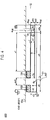
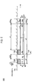
- Figs. 2 to 6 are plane views of vehicle glass antennas in which the shape of the antenna element 4 of the vehicle glass antenna 100 shown in Fig. 1 is changed into various shapes.
- the antenna element 4 extends from a point on the antenna element 2 (which includes the terminating end portion 1 g and the terminating end portion 2g) as a starting point
- an antenna element 4 extends rightwards from a terminating end portion 1 g as a starting point.
- an antenna element 4 includes an element base portion 4a which extends rightwards from a terminating end portion 1g as a starting point and bent portions (4b, 4c) of which one extends downwards from a base portion terminating end portion 4ag where the rightward extension of the element base portion 4a terminates and the other is bent leftwards from where the downward extension of the one bent portion terminates so as to extend parallel to the element base portion 4a.
- element base portion 4a which extends rightwards from a terminating end portion 1g as a starting point and bent portions (4b, 4c) of which one extends downwards from a base portion terminating end portion 4ag where the rightward extension of the element base portion 4a terminates and the other is bent leftwards from where the downward extension of the one bent portion terminates so as to extend parallel to the element base portion 4a.
- an antenna element 4 includes an element base portion 4a which extends rightwards from a terminating end portion 2g as a starting point and bent portions (4b, 4c) of which one extends upwards from a base portion terminating end portion 4ag where the rightward extension of the element base portion 4a terminates and the other is bent leftwards from where the upward extension of the one bent portion terminates so as to extend parallel to the element base portion 4a.
- a terminating end portion 4cg where the extension of the constituent element 4c of the bent portions (4b, 4c) terminates is positioned to the right of an antenna element 2.
- Figs. 3 a terminating end portion 4cg where the extension of the constituent element 4c of the bent portions (4b, 4c) terminates is positioned to the right of an antenna element 2.
- an antenna element 4 includes, as constituent elements of an element base portion 4a, an element base portion 4aa which extends rightwards from a terminating end portion 1g as a starting point and an element base portion 4ab which extends rightwards from a terminating end portion 2g as a starting point
- the antenna element 4 may include one antenna base portion which extends rightwards from one point on the antenna element 2 as a starting point (refer to Figs. 1 to 4 ) or may include a plurality of antenna base portions which extend rightwards from a plurality of points on the antenna element 2 as starting points (refer to Figs. 5 and 6 ). Further, in the case of Fig.
- an antenna element 3 includes, as part of the antenna element 3, additional element portions (3b, 3c) of which one extends upwards from a terminating end portion 3ag and the other is bent rightwards from where the upward extension of the one additional element portion terminates so as to extend parallel to an antenna element 3a.
- a terminating end portion where the rightward extension of the constituent element 3c of the additional element portions (3b, 3c) terminates is positioned to the left of the antenna element 2.
- the parasitic element 5 only has to extend downwards from a point on a lower side of the ground portion 16B as a starting point to terminate at a terminating end portion 5g.
- a starting point of the antenna element 1 in Fig. 1 is a point on the lower side of the ground portion 16B which lies further leftwards than a central point thereof. The starting point may be an intersection point between a left side and the lower side of the ground portion 16B.
- the parasitic element 6 only has to extend rightwards from the terminating end portion 5g as a starting point to terminate at a terminating end portion 6g.
- Figs. 7 , 8 are plan views of vehicle glass antennas in which the shape of the parasitic element 6 of the vehicle glass antenna 100 shown in Fig. 1 is changed variously.
- a parasitic element 6 extends horizontally through a terminating end portion 5g.
- a parasitic element 6 extends leftwards from a terminating end portion 5g as a starting point to terminate at a terminating end portion 6g.
- a parasitic element 6 extends both leftwards and rightwards from a terminating end portion 5g as a starting point to terminate at terminating end portions 6rg, 61g.
- a preferred result can be obtained in increasing an antenna gain in the broadcasting frequency band in the event that a sum of a conductor length x5 of the parasitic element 5 and a conductor length x6 of the parasitic element 6 is in the range of (4/64) ⁇ g to (13/64) ⁇ g (in particular, in the range of (6/64) ⁇ g to (11/64) ⁇ g )
- x5 is preferably in the range of (1/64) ⁇ g to (5/64) ⁇ g (in particular, in the range of (2/64) ⁇ g to (4/64) ⁇ g
- x6 is preferably in the range of (3/64) ⁇ g to (8/64) ⁇ g (in particular, in the range of (4/64) ⁇
- the central frequency of the Japanese terrestrial digital TV broadcasting frequency band (470 to 770 MHz), for example, is 620 MHz, and ⁇ g in 620 MHz is 309.7 mm.
- a frequency band of 470 to 600 MHz in the terrestrial digital TV broadcasting frequency band at which the current broadcasting is performed is a frequency band to be received
- 535 MHz can be set as a central frequency
- a frequency band of 470 to 710 MHz in the terrestrial digital TV broadcasting frequency band is a frequency band to be received
- 590 MHz can be set as a central frequency.
- the central frequency of the terrestrial digital TV broadcasting frequency band (473 to 713 MHz) is about 600 MHz (strictly speaking, 593 MHz), and therefore, (x5+x6) is to be adjusted to a range of 20 to 65 mm (in particular, a range of 30 to 55 mm).
- x5 is to be adjusted to a range of 5 to 25 mm (in particular, a rage of 10 to 20 mm)
- x6 is to be adjusted to a range of 15 to 40 mm (in particular, a range of 20 to 35 mm).
- a preferred result can be obtained in increasing an antenna gain in the broadcasting frequency band in the event that a sum of a conductor length x1 of the antenna element 1 and a conductor length x2 of the antenna element 2 and a conductor length x3 of the antenna element 3 is in the range of (37/64) ⁇ g to (57/64) ⁇ g (in particular, in the range of (42/64) ⁇ g to (52/64) ⁇ g ).
- x1 is preferably in the range of (16/64) ⁇ g to (24/64) ⁇ g (in particular, in the range of (18/64) ⁇ g to (22/64) ⁇ g )
- x2 is preferably in the range of (1/64) ⁇ g to (5/64) ⁇ g (in particular, in the range of (2/64) ⁇ g to (4/64) ⁇ g )
- x3 is preferably in the range of (20/64) ⁇ g to (28/64) ⁇ g (in particular, in the range of (22/64) ⁇ g to (26/64) ⁇ g ).
- the central frequency of the terrestrial digital TV broadcasting frequency band (473 to 713 MHz) is about 600 MHz (strictly speaking, 593 MHz), and therefore, (x1+x2+x3) is to be adjusted to a range of 185 to 285 mm (in particular, a range of 210 to 260 mm).
- x1 is to be adjusted to a range of 80 to 120 mm (in particular, a range of 90 to 110 mm)
- x2 is to be adjusted to a range of 5 to 25 mm (in particular, a range of 10 to 20 mm)
- x3 is to be adjusted to a range of 100 to 140 mm (in particular, a range of 110 to 130 mm).
- a preferred result can be obtained in increasing the antenna gain in the broadcasting frequency band in the event that a conductor length L1 of the antenna element from one starting point on the antenna element 2 from which it extends rightwards to the terminal point where the rightward extension of the antenna element terminates (in the case of Figs. 1 and 2 , the conductor length L1 corresponds to x4, in the case of Figs.
- the conductor length L1 corresponds to (x4a+x4b+x4c), and in the case of Figs. 5 and 6 , the conductor length L1 corresponds to x4aa (x4ab)) is in the range of (3/64) ⁇ g to (14/64) ⁇ g (in particular, in the range of (6/64) ⁇ g to (13/64) ⁇ g ).
- the central frequency of the terrestrial digital TV broadcasting frequency band (473 to 713 MHz) is about 600 MHz (strictly speaking, 593 MHz), and therefore, L1 is to be adjusted to a range of 15 to 70 mm (in particular, a range of 30 to 65 mm).
- a preferred result can be obtained in increasing the antenna gain in the broadcasting frequency band in the event that a distance xs1 of a horizontal component between an end portion of a most leftward antenna conductor of the antenna element 3 and an end portion of a most rightward parasitic conductor element of the parasitic conductor elements which make up the parasitic conductors is in the range of -(5/64) ⁇ g to (1/64)) ⁇ g (in particular, in the range of -(4/64) ⁇ g to (1/64) ⁇ g ).
- the end portion of the most leftward antenna conductor of the antenna element 3 corresponds to the third terminating end portion 3g in the case of Fig. 1 and corresponds to the constituent element 3b of the additional element portions in the case of Fig. 6 .
- the end portion of the most rightward parasitic conductor element of the parasitic conductor elements which make up the parasitic conductors corresponds to the terminating end portion 6g in the case of Fig. 1
- xs1 becomes positive when the position of the end portion of the parasitic conductor passes through the end portion of the most rightward antenna conductor and is positioned to the right of an imaginary straight line 21 which is parallel to the second direction, whereas when the position of the end portion of the parasitic conductor is positioned to the left of the imaginary straight line 21, xs1 becomes negative.
- the central frequency of the terrestrial digital TV broadcasting frequency band (473 to 713 MHz) is about 600 MHz (strictly speaking, 593 MHz), and therefore, xs1 is to be adjusted to a range of-25 to 5 mm (in particular, a range of-20 to 5 mm).
- the vehicle glass antenna has been described as being applied to reception of radio waves in the Japanese terrestrial digital TV broadcasting frequency band
- the invention can also preferably be applied to reception of terrestrial digital TV broadcasting frequency bands of other foreign countries, and when a broadcasting frequency band to be received falls within a range of 470 to 862 MHz, the invention functions preferably as a glass antenna.
- Figs. 1 to 8 show the cases where the glass antenna is disposed on the window glass 12.
- Reference numeral 15a denotes an upper edge of an opening in the vehicle body and is disposed in an upper area of the window glass 12.
- the glass antenna By being made smaller in size of the glass antenna, even in the event that the upper area of the window glass 12 is narrowed by the formation of a defogger in a central area of the window glass 12, the glass antenna can easily be disposed in the narrowed area.
- the glass antenna may be disposed in a central upper area, a central left-hand side area, a central right-hand side area or a lower area of the window glass 12.
- a glass antenna which is laterally symmetrical with any of the embodiments shown in Figs. 1 to 8 may be disposed in an upper right-hand side area of the window glass 12. This will be true with lower areas of the window glass 12.
- a glass antenna may be formed by forming a conductor layer given synthetic resin film in which a conductor layer of an antenna conductor is provided in the inside or on a surface, of a synthetic resin film on an inner surface of an outer surface of a pane of window glass. Further, a glass antenna may be formed by forming a flexible circuit board on which an antenna conductor is formed on an inner surface or an outer surface of a pane of window glass.
- a mounting angle of the window glass relative to the vehicle is preferably in the range of 15 to 90° and is more preferably in the range of 30 to 90°.
- a concealing coating may be formed on the surface of the window glass, so that part or the whole of the antenna conductor is provided on the concealing coating. Ceramics such as a black ceramic coating can be raised as a concealing coating. As this occurs, when the window glass is seen from an outer side thereof, the antenna conductor portion provided on the concealing coating becomes invisible from the outside of the vehicle due to the concealing coating, resulting in the well designed window glass.
- the antenna conductor portion provided on the concealing coating becomes invisible from the outside of the vehicle due to the concealing coating, resulting in the well designed window glass.
- the configurations shown in the drawings by forming at least part of the feeding portion, the ground portion, the antenna conductor and the parasitic conductor on the concealing coating, only the thin straight portions of the conductors are seen from the outside of the vehicle, which is preferable from the viewpoint of design.
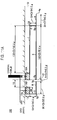
- Fig. 11A is an exemplary diagram of a feeding structure of the glass antenna 100 according to the invention
- Fig. 11B is an explanatory diagram of a feeding structure of a conventional glass antenna X ( JP-A-2007-110390 ).
- the glass antenna 100 is suitable for reception of radio waves of a high-frequency band and is particularly suitable for reception of the terrestrial digital TV broadcasting frequency band (470 to 770 MHz). It is understood that respective dimensions of portions of the glass antennas take values (in mm) shown in Figs. 11A and 11B .
- a conductor width of each element is 0.8 mm.
- the feeding portion 16A and the ground portion 16B have the same size. This will be true with the other diagrams that will be described later.
- the inner conductor of the coaxial cable which is connected to the signal processing circuit is connected to the feeding portion 16A, and the outer conductor thereof is ground connected to the vehicle body. Further, the ground portion 16B is also ground connected to the vehicle body.
- an inner conductor of a coaxial cable which is connected to a signal processing circuit is connected to a feeding portion, and an outer conductor thereof is ground connected to a vehicle body.
- the parasitic conductor of the glass antenna 100 is ground connected to the vehicle body
- a parasitic conductor of the glass antenna X is not ground connected to the vehicle body.
- Antenna gains were measured every 3° while turning a automobile in which a window glass is mounted while inclined at 15° relative to a horizontal direction through 360° by radiating radio waves to the vehicle.
- Radio waves were horizontal polarized waves, and frequencies were changed every 6 MHz within the frequency range of 473 to 713 MHz.
- Antenna gains were standardized based on a ⁇ /2 dipole antenna so that the antenna gain of the ⁇ /2 dipole antenna became 0 dB.
- Fig. 12 is an antenna gain frequency characteristic chart showing frequency characteristics of the antenna gains of the glass antenna 100 and the glass antenna X.
- the antenna gain denoted by an axis of ordinates shows mean values of antenna gains measured every 3° ° while turning the automobile through 360° (mean values of antenna gains measured in steps of 6 MHz within the overall frequency band of 473 to 713 MHz). This will be true with the other charts.
- Fig, 13 is a directivity characteristic chart showing the directivity of every frequency received of the glass antenna 100 and the glass antenna X.
- the directivity characteristic chart shows directivity characteristics of the glass antennas mounted on the windscreen around the whole circumference of the vehicle and shows mean values of the antenna gains of the glass antennas measured every 3° and in steps of 6 MHz within the overall frequency band of 473 to 713 MHz.
- An upper half of the chart corresponds to a front area of the vehicle and a lower half of the chart corresponds to a rear area of the vehicle.
- Table 1 is a summary of the data shown in Figs. 12,13 .
- an average gain of the glass antenna 100 is -3.5 dB, and an average gain of the glass antenna X is -3.5 dB.
- the glass antenna 100 ensures the same average gain as that of the conventional glass antenna X.
- the F/B ratio of the glass antenna 100 is 6.0, and the F/B ratio of the glass antenna X is 9.1.
- the glass antenna 100 has smaller difference between sensitivities at the front and rear of the vehicle than those of the conventional glass antenna X.
- the antenna gain of the glass antenna 100 in the vehicle's width direction is superior to that of the conventional glass antenna X.
- the F/B ratio means a difference between an antenna gain mean value (every 1°) in a horizontal direction of -90° to +90° and an antenna gain mean value (every 1°) in a horizontal direction of +90° to +270° when a forward direction of the vehicle is referred to as 0 "zero" degree, a leftward direction of the vehicle as +90° and a rearward direction of the vehicle as +180°.
- the area mean calculation method is used in calculating a mean antenna gain.
- Fig. 14 is a chart showing actually measured data of the antenna gain of the glass antenna 100 having the conductor pattern shown in Fig. 1 when the conductor length x4 was changed. No ground portion and parasitic conductor are provided in order to verify the effect of the conductor length x4. When the conductor length x4 is zero, this means that the antenna element 4 is not provided, and x4 increases as the antenna element 4 extends rightwards.
- the conductor length x4 is not less than 15 mm and not more than 70 mm (in particular, not less than 30 mm and not more than 65 mm) in increasing the antenna gain.
- Fig. 15 is a chart showing actually measured data of the antenna gain of the glass antenna 100, shown in Fig. 1 , having a conductor pattern in which no antenna element 4 is provided when the horizontal overlapping distance xs1 of the terminating end portion 3g and the terminating end portion 6g was changed.
- the overlapping distance xs1denoted by an axis of ordinates takes a positive value, this means that the two elements 3 and 6 are in such a positional relationship that a vertical projection of one element in the chart overlaps the other element
- the overlapping distance xs1takes a negative value this means that the two elements 3 and 6 are in such a positional relationship that the two elements do not overlap each other.
- xs1 when the overlapping distance xs1 takes a positive value, this means that the antenna element 3 and the parasitic element 6 overlap each other, whereas when the overlapping distance xs1takes a negative value, this means that a horizontal space exists between the terminating end portion 3g and the terminating end portion 6g.
- x6 is 35 mm, xs1is zero.
- the antenna gain is increased when the vertical projections of the elements 3 and 6 do not overlap each other, compared with when the vertical projections thereof overlap each other.
- the horizontal space between the terminating end portion 3g and the terminating end portion 6g is preferably in the range of -25 to 5 mm (in particular, in the range of -20 to 5 mm).
- Fig. 16 is an antenna gain frequency characteristic chart showing frequency characteristics of antenna gains of glass antennas 100 to 600. The chart compares changes in antenna gain which are caused by glass antennas according to the invention which have different patterns of antenna conductors.
- Table 2 is a summary of the data shown in Fig. 16 .
- the average gain of the glass antenna 100 is the highest
- the glass antennas 100 to 600 realize a reduction in size while ensuring the same antenna gain.
- Fig. 17 is an antenna gain frequency characteristic chart showing frequency characteristics of antenna gains of glass antennas 100A, 100B, 700 to 900.
- the chart compares changes in antenna gain which are caused by glass antennas according to the invention which have different patterns of parasitic conductors.
- the glass antenna 100A and the glass antenna 100B differ in the conductor length x5 of the parasitic element 5 in the embodiment of the glass antenna 100 shown in Fig. 1 .
- the dimensions of the parasitic conductors of the glass antennas shown in Figs. 1 , 7 , 8 and 9 are:
- Table 3 is a summary of the data shown in Fig. 17 .
- the average gains of the glass antenna 100A, 100B, 700 and 800 show higher values than the average gain of the glass antenna 900 which has no parasitic conductor.
- the antenna pattern can be made smaller in size while ensuring a superior antenna characteristic which covers a wide bandwidth.
- the reception sensitivity of radio waves from the vehicle's width direction can be increased.
- a substantially circular directivity about the vehicle can be obtained, thereby making it possible to increase the reception sensitivity from the vehicle's width direction.
- the invention is used for automobile glass antennas for receiving the terrestrial digital TV broadcasting and analog TV broadcasting in Japan, as well as the digital TV broadcasting (698 to 806 MHz) in the United States, the digital TV broadcasting (470 to 862 MHz) in the regions within the European Union or the digital TV broadcasting in People's Republic of China.
- the invention can also be used for the FM broadcasting band (76 to 90 MHz) in Japan, the FM broadcasting band (88 to 108 MHz) in the United States, the TV VHF bands (90 to 108 MHz, 170 to 222 MHz), the 800 MHz band (810 to 960 MHz) for automobile mobile phones, the 1.5 GHz band (1.429 to 1.501 GHz) for automobile mobile phones, the UHF band (300 MHz to 3 GHz), GPS (Global Positioning System), the GPS signal (1575.42 MHz) from artificial satellites, and VICS (trade name) (Vehicle Information and Communication System: 2.5 GHz).
- the invention can also be used for communication for ETC (Electronic Toll Collection System: Non-stop automatic toll correction system, transmission frequency for roadside radio communication system: 5.795 GHz or 5.805 GHz, reception frequency for roadside radio communication system: 5.835 GHz or 5.845 GHz), DSRC (Dedicated Short Range Communication, 915 MHz band, 5.8 GHz band, 60 GHz band), microwaves (1 GHz to 3 THz), millimeter waves (30 to 300 GHz), keyless entry system for vehicle (300 to 450 MHz), and SDARS (Satellite Digital Audio Radio Service (2.34 GHz, 2.6 GHz). Description of Reference Numerals and Character
Landscapes
- Details Of Aerials (AREA)
- Support Of Aerials (AREA)
Abstract
Description
- The present invention relates to a vehicle glass antenna in which an antenna conductor and a parasitic conductor are provided to a widow glass and a vehicle window glass, and a feeding structure for a vehicle glass antenna.
- Conventionally, there has been known a glass antenna like one described in
JP-A-2007-110390 JP-A-2007-110390 - With the conventional glass antennas, they exhibit a superior reception sensitivity in a front-to-rear direction of a vehicle by being placed on at least one of a windscreen glass and a rear window glass of the vehicle. However, no sufficient antenna gain is obtained in a lateral direction of the vehicle. On the other hand, there has been a demand for smaller glass antennas due to vehicle design and the visibility of an occupant of the vehicle.
- Then, an object of the invention is to provide a vehicle glass antenna and a vehicle window glass, and a feeding structure for a vehicle glass antenna which can increase the reception sensitivity in a lateral direction of a vehicle while making smaller a glass antenna which is suitable for reception of radio waves of a high-frequency wave band for the terrestrial digital broadcasting.
- In order to achieve the above object, the present invention provides a vehicle glass antenna in which an antenna conductor, a feeding portion which is connected to the antenna conductor, a parasitic conductor and a ground portion which is connected to the parasitic conductor are provided on a window glass, characterized in that
the feeding portion constitutes a part which electrically connects the antenna conductor to a signal processing circuit installed in a vehicle, and the ground portion constitutes a part which electrically connects the parasitic conductor to a vehicle body, whereby the window glass is installed in the vehicle, in that
the feeding portion and the ground portion are disposed so as to be aligned along a reference direction, in that
the antenna conductor comprises: - a first element extended from the feeding portion as a starting point in a first direction, wherein the first direction is parallel to the reference direction and is directed to an opposite side to the ground portion;
- a second element connected to a first terminating portion which constitutes an end of the first element disposed the opposite to the feeding portion and extends in a second direction, wherein the second direction is at right angles to the first element and is directed inwards of an outer circumference of the window glass; and
- a third element extended from the second element as a starting point in a third direction, wherein the third direction is a direction opposite to the first direction, and in that
- the parasitic conductor comprises a parasitic element at least part of which extends from the ground portion as a starting point in the second direction.
- Further, it is preferable that the antenna conductor comprises a fourth element which extends from the second element as a starting point in the first direction.
- Further, it is preferable that the parasitic conductor comprises an accessory parasitic element which is parallel to the reference direction and is connected to the parasitic element.
- Further, in order to achieve the above object, the present invention provides a vehicle window glass on which the glass antenna according to the present invention is provided.
- Further, in order to achieve the above object, the present invention provides a vehicle glass antenna feeding structure comprising the vehicle window glass according to the present invention;
a first conductive member which electrically connects the feeding portion to the signal processing circuit; and
a second conductive member which electrically connects the ground portion to the vehicle body. - According to the present invention, it is possible to increase the reception sensitivity in a lateral direction of a vehicle while making smaller a glass antenna which is suitable for reception of radio waves of a high-frequency wave band for the terrestrial digital broadcasting.
-
-
Fig. 1 is a plan view of avehicle glass antenna 100. -
Fig. 2 is a plan view of avehicle glass antenna 200. -
Fig. 3 is a plan view of avehicle glass antenna 300. -
Fig. 4 is a plan view of avehicle glass antenna 400. -
Fig. 5 is a plan view of avehicle glass antenna 500. -
Fig. 6 is a plan view of avehicle glass antenna 600. -
Fig. 7 is a plan view of avehicle glass antenna 700. -
Fig. 8 is a plan view of avehicle glass antenna 800. -
Fig. 9 is a plan view of avehicle glass antenna 900. -
Fig. 10A is a sectional view showing a feeding structure of a feeding portion. -
Fig. 10B is a sectional view showing a feeding structure of a ground portion. -
Fig. 11A is a diagram of a feeding structure of theglass antenna 100 according to the embodiment of the invention. -
Fig. 11B is a diagram of a feeding structure of a conventional glass antenna X -
Fig. 12 is an antenna gain frequency characteristic chart of theglass antenna 100 and the glass antenna X. -
Fig. 13 is a directivity characteristic chart showing directivity of theglass antenna 100 and the glass antenna X. -
Fig. 14 is actually measured data of the antenna gain when a conductor length x4 was changed. -
Fig. 15 is actually measured data of the antenna gain when a horizontal overlapping distance xs1 of a terminatingend portion 3 g and a terminatingend portion 6g was changed. -
Fig. 16 is an antenna gain frequency characteristic chart ofglass antennas 100 to 600. -
Fig. 17 is an antenna gain frequency characteristic chart ofglass antennas -
Fig. 18 is a sectional view showing a feeding structure of a ground portion according to a embodiment different fromFig, 10B . -
Fig. 19 is a perspective view showing an elastic connectingmember 31 which is a second conductive member. -
Fig. 20 is a sectional view showing a feeding structure of a ground portion according to a embodiment different fromFig. 10B . - Hereinafter, referring to the drawings, a embodiment for carrying out the invention will be described. In the drawings which depict the embodiment, when directions are mentioned without mentioning any specific direction in which the drawings are seen, directions on the drawings are to be referred to. In addition, although the drawings show views of antennas when they are seen from the inside of a passenger compartment of the vehicle, the drawings may be referred to as those showing views of the antennas when they are seen from the outside of the passenger compartment of the vehicle. For example, in the case of a window glass being a windscreen which is mounted at a front portion of the vehicle, a left-to-right direction on each of the drawings corresponds to a vehicle width direction. In addition, although a feeding portion and a ground portion are disposed so as to be aligned along a reference direction in the invention, the reference direction can be set freely depending on a region where to place a glass antenna. In particular, in the case of a window glass of a vehicle, the reference direction is preferably set in a direction parallel to an edge portion of the window glass, a horizontal direction or a vertical direction.
In an embodiment which will be described below, a horizontal plane when a vehicle window glass is installed in a vehicle constitutes a reference direction. The invention is not limited to the application to a windscreen but may be applied to a rear window glass which is mounted at a rear portion of the vehicle or a side window glass which is mounted in a side portion of the vehicle. -
Fig. 1 is a plan view of avehicle glass antenna 100 according to the invention. Thevehicle glass antenna 100 is an antenna in which an antenna conductor, a parasitic conductor, a feedingportion 16 and aground portion 16B are provided on avehicle window glass 12 in a planar fashion, the parasitic conductor being disposed in the vicinity of the antenna conductor, the feedingportion 16A and theground portion 16B being spaced away from each other in a predetermined reference direction (for example, a horizontal or substantially horizontal direction). - The
vehicle glass antenna 100 includes, as an antenna conductor pattern, anantenna element 1 as a first element, anantenna element 2 as a second element, anantenna element 3 as a third element, and anelement 4 as a fourth element Theantenna element 1 extends from the feedingportion 16A as a starting point in a first direction (a rightward direction in the drawings) which is parallel to the reference direction and is directed towards an opposite side of theground portion 16B.
Theantenna element 2 is connected to a first terminatingend portion 1 g (that is, a terminating end opposite to the feedingportion 16A) being the end of theantenna element 1 in the first direction and extends in a second direction (a downward direction in the drawings) which is at right angles to theantenna element 1 and is directed inwards relative to an outer circumference of thewindow glass 12. Theantenna element 2 may extend from the terminatingend portion 1g as a starting point in a straight line towards the second direction or may extend towards the second direction in a curved fashion. Theantenna element 3 extends from a second terminatingend portion 2g being the end of theantenna element 2 as a starting point in a third direction (a leftward direction in the drawings) which is an opposite direction to the first direction. Then, a third terminatingend portion 3g being the end of theantenna element 3 in the third direction is positioned on the first direction side relative to aparasitic element 5, which will be described later (that is, the third terminatingend portion 3g is positioned in a right-hand region relative to the parasitic element 5). Theantenna element 4 extends from a point on theantenna element 2 as a starting point in the first direction. The starting point of theantenna element 4 inFig. 1 is the terminatingend portion 2g from which theantenna element 4 extends in the first direction. - Although the
antenna element 4 may be omitted, as will be described later, an average sensitivity of a glass antenna in which theantenna element 4 is provided is increased, compared with a glass antenna in which theantenna element 4 is not provided. - In addition, as a parasitic conductor pattern, the
vehicle glass antenna 100 includes theparasitic element 5 which is a parasitic element and aparasitic element 6 which is an accessory parasitic element. Theparasitic element 5 is an element at least part of which extends from theground portion 16B as a starting point in the second direction. Theparasitic element 6 extends parallel to the reference direction while being connected to theparasitic element 5 and passes through a fifth terminatingend portion 5g being the end of theparasitic element 5 in the second direction. - Although the
parasitic element 6 may be omitted, an average sensitivity of a glass antenna in which theparasitic element 6 is provided is increased, compared with a glass antenna in which theparasitic element 6 is not provided. - Here, the "terminating end portion" may be a terminal point of the extension of the parasitic elements or the antenna elements or a conductor portion in front of and in the vicinity of the terminal point
- The feeding
portion 16A and the antenna conductor connected to the feedingportion 16A, and theground portion 16B and the parasitic conductor connected to theground portion 16B are formed by printing and baking a paste containing a conductive metal such as a silver paste on an inner surface of a pane of window glass. However, the invention is not limited to this forming method. A linear element or a foil element made of a conductive material such as copper may be formed on an inner or outer surface of a window glass or may be affixed to a window glass with an adhesive or may be provided in an inside of a window glass itself. - With a conventional glass antenna, in the case of a glass antenna having a feeding portion and a ground portion, a dipole antenna is used as the glass antenna. In this dipole antenna, an inner conductor of a coaxial cable is connected to the feeding portion, while an outer conductor of the coaxial cable is connected to the ground portion, and the coaxial cable connects from the glass antenna to an amplifier. The vehicle glass antenna of the invention differs from the conventional glass antenna in that the
ground portion 16B is connected directly to a vehicle body panel, and a monopole antenna is used as the glass antenna. A reception signal of a radio wave received by the antenna conductors is transmitted to a signal processing circuit installed in the vehicle via a first conductive member which is electrically connected to the feedingportion 16A corresponding to a feeding point. On the other hand, the parasitic conductor is grounded to a vehicle body via a second conductive member which electrically connects theground portion 16B with the vehicle body. The electrical connection includes a case where the conductors are brought into direct connection with each other so as to establish an electric communication therebetween in a direct current fashion and a case where the conductors are spaced a predetermined distance apart from each other so as to form a capacitor for electric communication with each other in a high-frequency wave fashion. - Fig. l0A is a sectional view showing a connecting structure example which electrically connects the feeding
portion 16A with asignal processing circuit 20.Fig. 10B is a sectional view showing an example of a connecting structure which ground connects theground portion 16B with the vehicle body, - In
Figs. 10A and 10B ,reference numeral 12 denotes a vehicle window glass, andreference numeral 11 denotes a vehicle body panel (an overall view of which is omitted) which is made up of aninner panel 11a and anouter panel 11b, and an L-shaped flange is formed at an end portion of each panel so that thewindow glass 12 is placed in the vehicle body.Reference numeral 13 denotes an adhesive (or a packing) with which the flange of thebody panel 11 and thewindow glass 12 are bonded together.Reference numeral 14 denotes an antenna unit disposed inside a passenger compartment (shown in a lower part of each drawing),reference numeral 18 denotes an amplifier case fixed to an inner side of the inner panel. 11a, andreference numeral 20 denotes a signal processing circuit (for example, a printed circuit board on which a reception circuit such as an amplifier is mounted) provided in aninterior portion 19 of theamplifier case 18.Reference numeral 22 denotes an insulation sheet, andreference numerals Reference numeral 29A denotes a joining member as a first conductive member which is held so as to extend and contract within a cylindrical portion of theholder 28A and which is disposed below the feedingportion 16A so as to face it Reference numeral 29B denotes a joining member as a second conductive member which is held so as to extend and contract within a cylindrical portion of theholder 28B and which is disposed below theground portion 16B so as to face it.Reference numeral 30A denotes a conductive connecting member which electrically connects a lower end face of the joiningmember 29A with thesignal processing circuit 20, and reference numeral 30B denotes a conductive connecting member which electrically connects a lower end face of the joiningmember 29B with acover 24 of theamplifier case 18. - The
amplifier case 18 includes abase member 23 having a substantially crank-shaped section and thecover 24 held in thebase member 23. Thebase member 23 is held on theinner panel 11a, which is a ground member on the vehicle body side, by screwing abolt 27 into anut 26 fixed to theinner panel 11a. Thebase member 23 and thecover 24 may be made of a metal or may be such that a conductor is affixed to an overall surface of a resin body. - By adopting this structure, a reception signal of a radio wave received by the antenna conductors of the glass antenna can be supplied surely to the
signal processing circuit 20 by way of the feedingportion 16A, the joiningmember 29A and the connectingmember 30A. In addition, theground portion 16B and the parasitic conductor connected to theground portion 16B of the glass antenna can be grounded surely to the vehicle body via the joiningmember 29B, the connectingmember 30B and (thecover 24 of) theamplifier case 18. - A greater detailed description on the structure shown in
Fig. 10A is common to the details of a similar structure disclosed inJP-A-2003-347817
In addition, in place of the joiningmember 29B and the connectingmember 30B, as is shown inFig. 18 , an elastic connectingmember 31 is provided as a second conductive member on theground portion 16B so that theground portion 16B is electrically connected to the vehicle body. As is shown inFig. 19 , the elastic connectingmember 31 is made up of ametallic plate 35 having connectingportions 34 electrically connected to theground portion 16B through soldering andelastic plates 33 placed on themetallic plate 35 while being curved into an arch-like shape. The elastic connectingmember 31 may be connected to theground portion 16B in a high-frequency wave fashion by bonding themetallic plate 35 to theground portion 16B with an adhesive. In the elastic connectingmember 31 placed on theground portion 16B, when thewindow glass 12 is bonded to an end portion of thevehicle body panel 11 via an adhesive 13, theelastic plates 33 are elastically deformed so as to be brought into surface contact with thevehicle body panel 11. By adopting this structure, with no specific configuration being provided on the vehicle body side, theground portion 16B can be ground connected to thevehicle body panel 11.
On the other hand, an outer surface of theouter panel 11b of thevehicle body panel 11 is normally painted with a paint so that an insulatingpaint coating 32 is formed thereon, and no direct current-like electric connection is established only by the elastic connectingmember 31 being brought into contact with thevehicle body panel 11. However, by an area over which theelastic plates 33 are in contact with thepaint coating 32 being increased sufficiently after elastic deformation thereof, the elastic connectingmember 31 is connected to theouter panel 11b in a high-frequency wave fashion, thereby making it possible for theground portion 16B to be grounded to the vehicle body.
The embodiments shown inFigs. 10B and18 are examples of second conductive members, and the second conductive member only has to be a means for electrically connecting theground portion 16B with thevehicle body panel 11. A configuration may be adopted in which a projecting conductive member is placed on theground portion 16B, so that the projecting conductive member is brought into fitting contact with a flange of the vehicle body on which the pane of window glass is attached. In addition, in place of the second conductive member, a projectingportion 36 shown inFig. 20 may be provided at an end portion of theouter panel 11b of thevehicle body panel 11. Theground portion 16B comes into direct contact with thevehicle body panel 11 when theground portion 16B comes into contact with the projectingportion 36, whereby theground portion 16B can be grounded to the vehicle body. In this case, too, even though an insulatingpaint coating 32 is formed on theouter panel 11 b, the area where theground portion 16B and the projectingportion 36 face each other can be increased to a sufficient area, whereby the projectingportion 36 is brought into contact with theouter panel 11b in a high-frequency wave fashion. Therefore, theground portion 16B can be grounded to the vehicle body. In addition, this will be true even when theground portion 16B and the projectingportion 36 are not in direct contact with each other. - In addition, when a coaxial cable is used as a feeder line for feeding the antenna conductors via the feeding
portion 16A, an inner conductor of the coaxial cable may electrically be connected to the feedingportion 16A, while an outer conductor of the coaxial cable may be ground connected to the vehicle body. In addition, the outer conductor of the coaxial cable may be connected to theground portion 16B so as to be ground connected to the vehicle body via theground portion 16B. - In addition, a configuration may also be adopted in which a connector for electrically connecting a conductive member such as a conductor wire connected to the signal processing circuit with the feeding
portion 16A is mounted on the feedingportion 16A. A configuration may also be adopted in which a connector for electrically connecting a conductive member such as a conductor wire which is grounded to the vehicle body with theground portion 16B is mounted on theground portion 16B.
Additionally, a configuration may also be adopted in which a connector for electrically connecting the inner conductor of the coaxial cable with the feedingportion 16A and a connector for electrically connecting the outer conductor of the coaxial cable with theground portion 16B are mounted on the feedingportion 16A and theground portion 16B, respectively. In this case, theground portion 16B is electrically connected to the vehicle body without involvement of the connector, and the outer conductor of the coaxial cable is ground connected to the vehicle body via theground portion 16B. By using these connectors the inner conductor of the coaxial cable is easily connected to the feedingportion 16A, and the outer conductor of the coaxial cable is easily connected to theground portion 16B. Further, a configuration may be adopted in which an amplifier is mounted in the connector.
A conductor length of a line required for electric connection of theground portion 16B to thevehicle body panel 11 is preferably not longer than 50 mm in increasing the reception sensitivity. Namely, the second conductive member preferably has a conductor length of not longer than 50 mm which extends from theground portion 16B to the vehicle body. The second conductive member more preferably has a conductor length of not longer than 30 mm and much more preferably has a conductor length of not longer than 15 mm. The conductor length from theground portion 16B to the vehicle body is a conductor length D which is a total of a conductor length of the joiningmember 29B and a conductor length of the connectingmember 30B in the case of the embodiment shown inFig. 10B and is a conductor length D resulting when the elastic connectingmember 31 is brought into contact with thevehicle body panel 11 to thereby be elastically deformed in the case of the embodiment shown inFig. 18 . In addition, the conductor length D may be 0 mm, and in the embodiment shown inFig. 20 , a conductor length D is 0 mm. When theground portion 16B is connected to thevehicle body panel 11 in a high-frequency wave fashion, a conductor space for forming a capacitor is to be excluded. - The shapes of the
ground portion 16B and the feedingportion 16A and the space between theground portion 16B and the feedingportion 16A are determined in accordance with the shapes of the mounting surfaces where the joiningmembers member 31, the projectingportion 36 of the vehicle body panel or the connectors are mounted and the space between the mounting surfaces. In consideration of mounting these constituent members on theground portion 16B and the feedingportion 16A, for example, quadrangular shapes such as square, substantially square, rectangular and substantially rectangular shapes or polygonal shape are preferable. Alternatively, circular shapes such as circular, substantially circular, oval and substantially oval shapes may be adopted. The surface areas of theground portion 16B and the feedingportion 16A may be equal to or different from each other. In addition, in the case ofFig. 1 , theground portion 16B is provided in the vicinity of the feedingportion 16A in the third direction (on a left-hand side of the feedingportion 16A), and a right-hand side edge portion of theground portion 16B faces a left-hand side edge portion of the feedingportion 16A. In addition, it is a preferable embodiment in which an imaginary straight line which connects the center of gravity of theground portion 16B with the center of gravity of the feedingportion 16A is parallel to the direction in which theparasitic element 6 extends, is parallel to the direction in which theantenna element 1 extends and is parallel to the direction in which theantenna element 3 extends. -
Figs. 2 to 6 are plane views of vehicle glass antennas in which the shape of theantenna element 4 of thevehicle glass antenna 100 shown inFig. 1 is changed into various shapes. As is shown inFigs. 2 to 6 , theantenna element 4 extends from a point on the antenna element 2 (which includes the terminatingend portion 1 g and the terminatingend portion 2g) as a starting point In the case ofFig. 2 , anantenna element 4 extends rightwards from a terminatingend portion 1 g as a starting point. In the case ofFig. 3 , anantenna element 4 includes anelement base portion 4a which extends rightwards from a terminatingend portion 1g as a starting point and bent portions (4b, 4c) of which one extends downwards from a base portion terminating end portion 4ag where the rightward extension of theelement base portion 4a terminates and the other is bent leftwards from where the downward extension of the one bent portion terminates so as to extend parallel to theelement base portion 4a. In the case ofFig. 4 , anantenna element 4 includes anelement base portion 4a which extends rightwards from a terminatingend portion 2g as a starting point and bent portions (4b, 4c) of which one extends upwards from a base portion terminating end portion 4ag where the rightward extension of theelement base portion 4a terminates and the other is bent leftwards from where the upward extension of the one bent portion terminates so as to extend parallel to theelement base portion 4a. InFigs. 3 and4 , a terminating end portion 4cg where the extension of theconstituent element 4c of the bent portions (4b, 4c) terminates is positioned to the right of anantenna element 2. In the case ofFigs. 5 and6 , anantenna element 4 includes, as constituent elements of anelement base portion 4a, an element base portion 4aa which extends rightwards from a terminatingend portion 1g as a starting point and an element base portion 4ab which extends rightwards from a terminatingend portion 2g as a starting point Namely, theantenna element 4 may include one antenna base portion which extends rightwards from one point on theantenna element 2 as a starting point (refer toFigs. 1 to 4 ) or may include a plurality of antenna base portions which extend rightwards from a plurality of points on theantenna element 2 as starting points (refer toFigs. 5 and6 ). Further, in the case ofFig. 6 , anantenna element 3 includes, as part of theantenna element 3, additional element portions (3b, 3c) of which one extends upwards from a terminating end portion 3ag and the other is bent rightwards from where the upward extension of the one additional element portion terminates so as to extend parallel to anantenna element 3a. A terminating end portion where the rightward extension of theconstituent element 3c of the additional element portions (3b, 3c) terminates is positioned to the left of theantenna element 2. - On the other hand, in
Fig. 1 , theparasitic element 5 only has to extend downwards from a point on a lower side of theground portion 16B as a starting point to terminate at a terminatingend portion 5g. A starting point of theantenna element 1 inFig. 1 is a point on the lower side of theground portion 16B which lies further leftwards than a central point thereof. The starting point may be an intersection point between a left side and the lower side of theground portion 16B. - The
parasitic element 6 only has to extend rightwards from the terminatingend portion 5g as a starting point to terminate at a terminatingend portion 6g. -
Figs. 7 ,8 are plan views of vehicle glass antennas in which the shape of theparasitic element 6 of thevehicle glass antenna 100 shown inFig. 1 is changed variously. As is shown inFigs. 7 and8 , aparasitic element 6 extends horizontally through a terminatingend portion 5g. In the case ofFig. 7 , aparasitic element 6 extends leftwards from a terminatingend portion 5g as a starting point to terminate at a terminatingend portion 6g. In the case ofFig. 8 , aparasitic element 6 extends both leftwards and rightwards from a terminatingend portion 5g as a starting point to terminate at terminating end portions 6rg, 61g. - Incidentally, in the invention, assuming that a wavelength in the air at a central frequency of a broadcasting frequency band to be received is λ0, a glass shortening coefficient of wavelength is k (where k=0.64), and λg=λ0·k, a preferred result can be obtained in increasing an antenna gain in the broadcasting frequency band in the event that a sum of a conductor length x5 of the
parasitic element 5 and a conductor length x6 of theparasitic element 6 is in the range of (4/64)λg to (13/64)λg (in particular, in the range of (6/64)λg to (11/64)λg) In particular, x5 is preferably in the range of (1/64)λg to (5/64)λg (in particular, in the range of (2/64)λg to (4/64)λg, while x6 is preferably in the range of (3/64)λg to (8/64)λg (in particular, in the range of (4/64)λg to (7/64)λg). - Here, the central frequency of the Japanese terrestrial digital TV broadcasting frequency band (470 to 770 MHz), for example, is 620 MHz, and λg in 620 MHz is 309.7 mm. When a frequency band of 470 to 600 MHz in the terrestrial digital TV broadcasting frequency band at which the current broadcasting is performed is a frequency band to be received, 535 MHz can be set as a central frequency, whereas a frequency band of 470 to 710 MHz in the terrestrial digital TV broadcasting frequency band is a frequency band to be received, 590 MHz can be set as a central frequency.
- Consequently, when an antenna gain in a terrestrial digital TV broadcasting frequency band (473 to 713 MHz) is wanted to be increased, the central frequency of the terrestrial digital TV broadcasting frequency band (473 to 713 MHz) is about 600 MHz (strictly speaking, 593 MHz), and therefore, (x5+x6) is to be adjusted to a range of 20 to 65 mm (in particular, a range of 30 to 55 mm). As this occurs, x5 is to be adjusted to a range of 5 to 25 mm (in particular, a rage of 10 to 20 mm), and x6 is to be adjusted to a range of 15 to 40 mm (in particular, a range of 20 to 35 mm).
- In addition, in the invention, assuming that a wavelength in the air in a central frequency of a broadcasting frequency band to be received is λ0, a glass shortening coefficient of wavelength is k (where k=0.64), and λg=λ0·k, a preferred result can be obtained in increasing an antenna gain in the broadcasting frequency band in the event that a sum of a conductor length x1 of the
antenna element 1 and a conductor length x2 of theantenna element 2 and a conductor length x3 of theantenna element 3 is in the range of (37/64)λg to (57/64)λg (in particular, in the range of (42/64)λg to (52/64)λg). In particular, x1 is preferably in the range of (16/64)λg to (24/64)λg (in particular, in the range of (18/64)λg to (22/64)λg), x2 is preferably in the range of (1/64)λg to (5/64)λg (in particular, in the range of (2/64)λg to (4/64)λg), and x3 is preferably in the range of (20/64)λg to (28/64)λg (in particular, in the range of (22/64)λg to (26/64)λg). - Consequently, when the antenna gain in the terrestrial digital TV broadcasting frequency band (473 to 713 MHz) is wanted to be increased, the central frequency of the terrestrial digital TV broadcasting frequency band (473 to 713 MHz) is about 600 MHz (strictly speaking, 593 MHz), and therefore, (x1+x2+x3) is to be adjusted to a range of 185 to 285 mm (in particular, a range of 210 to 260 mm). As this occurs, x1 is to be adjusted to a range of 80 to 120 mm (in particular, a range of 90 to 110 mm), x2 is to be adjusted to a range of 5 to 25 mm (in particular, a range of 10 to 20 mm), and x3 is to be adjusted to a range of 100 to 140 mm (in particular, a range of 110 to 130 mm).
- In addition, in the invention, assuming that a wavelength in the air at a central frequency of a broadcasting frequency band to be received is λ0, a glass shortening coefficient of wavelength is k (where k=0.64), and λg=λ0·k, a preferred result can be obtained in increasing the antenna gain in the broadcasting frequency band in the event that a conductor length L1 of the antenna element from one starting point on the
antenna element 2 from which it extends rightwards to the terminal point where the rightward extension of the antenna element terminates (in the case ofFigs. 1 and2 , the conductor length L1 corresponds to x4, in the case ofFigs. 3 and4 , the conductor length L1 corresponds to (x4a+x4b+x4c), and in the case ofFigs. 5 and6 , the conductor length L1 corresponds to x4aa (x4ab)) is in the range of (3/64)λg to (14/64)λg (in particular, in the range of (6/64)λg to (13/64)λg). - Consequently, when the antenna gain in the terrestrial digital TV broadcasting frequency band (473 to 713 MHz) is wanted to be increased, the central frequency of the terrestrial digital TV broadcasting frequency band (473 to 713 MHz) is about 600 MHz (strictly speaking, 593 MHz), and therefore, L1 is to be adjusted to a range of 15 to 70 mm (in particular, a range of 30 to 65 mm).
- In addition, in the invention, assuming that a wavelength in the air at a central frequency of a broadcasting frequency band to be received is λ0, a glass shortening coefficient of wavelength is k (where k=0.64), and λg=λ0·k, a preferred result can be obtained in increasing the antenna gain in the broadcasting frequency band in the event that a distance xs1 of a horizontal component between an end portion of a most leftward antenna conductor of the
antenna element 3 and an end portion of a most rightward parasitic conductor element of the parasitic conductor elements which make up the parasitic conductors is in the range of -(5/64)λg to (1/64))λg (in particular, in the range of -(4/64)λg to (1/64)λg). - Here, the end portion of the most leftward antenna conductor of the
antenna element 3 corresponds to the third terminatingend portion 3g in the case ofFig. 1 and corresponds to the constituent element 3b of the additional element portions in the case ofFig. 6 . In addition, the end portion of the most rightward parasitic conductor element of the parasitic conductor elements which make up the parasitic conductors corresponds to the terminatingend portion 6g in the case ofFig. 1 , corresponds to theparasitic element 5 in the case ofFig. 7 and corresponds to the terminating end portion 6rg in the case ofFig. 8 . - In addition, as to positive and negative signs of xs1, xs1 becomes positive when the position of the end portion of the parasitic conductor passes through the end portion of the most rightward antenna conductor and is positioned to the right of an imaginary
straight line 21 which is parallel to the second direction, whereas when the position of the end portion of the parasitic conductor is positioned to the left of the imaginarystraight line 21, xs1 becomes negative. - Consequently, when the antenna gain of the terrestrial digital TV broadcasting frequency band (473 to 713 MHz), for example, is wanted to be increased, the central frequency of the terrestrial digital TV broadcasting frequency band (473 to 713 MHz) is about 600 MHz (strictly speaking, 593 MHz), and therefore, xs1 is to be adjusted to a range of-25 to 5 mm (in particular, a range of-20 to 5 mm).
- Thus, the vehicle glass antenna has been described as being applied to reception of radio waves in the Japanese terrestrial digital TV broadcasting frequency band, the invention can also preferably be applied to reception of terrestrial digital TV broadcasting frequency bands of other foreign countries, and when a broadcasting frequency band to be received falls within a range of 470 to 862 MHz, the invention functions preferably as a glass antenna.
Figs. 1 to 8 show the cases where the glass antenna is disposed on thewindow glass 12.Reference numeral 15a denotes an upper edge of an opening in the vehicle body and is disposed in an upper area of thewindow glass 12. By being made smaller in size of the glass antenna, even in the event that the upper area of thewindow glass 12 is narrowed by the formation of a defogger in a central area of thewindow glass 12, the glass antenna can easily be disposed in the narrowed area. In addition, the glass antenna may be disposed in a central upper area, a central left-hand side area, a central right-hand side area or a lower area of thewindow glass 12. - In addition, in the invention, when the glass antenna is disposed in an upper left-hand side area of the
window glass 12 in any of the embodiments shown inFigs. 1 to 8 , a glass antenna which is laterally symmetrical with any of the embodiments shown inFigs. 1 to 8 may be disposed in an upper right-hand side area of thewindow glass 12. This will be true with lower areas of thewindow glass 12. When the plurality of glass antennas are placed on thewindow glass 12 as has been described above, a diversity reception is enabled, which preferably increases the reception characteristics of the glass antennas. - Additionally, a glass antenna may be formed by forming a conductor layer given synthetic resin film in which a conductor layer of an antenna conductor is provided in the inside or on a surface, of a synthetic resin film on an inner surface of an outer surface of a pane of window glass. Further, a glass antenna may be formed by forming a flexible circuit board on which an antenna conductor is formed on an inner surface or an outer surface of a pane of window glass.
- A mounting angle of the window glass relative to the vehicle is preferably in the range of 15 to 90° and is more preferably in the range of 30 to 90°.
- Additionally, a concealing coating may be formed on the surface of the window glass, so that part or the whole of the antenna conductor is provided on the concealing coating. Ceramics such as a black ceramic coating can be raised as a concealing coating. As this occurs, when the window glass is seen from an outer side thereof, the antenna conductor portion provided on the concealing coating becomes invisible from the outside of the vehicle due to the concealing coating, resulting in the well designed window glass. In the configurations shown in the drawings, by forming at least part of the feeding portion, the ground portion, the antenna conductor and the parasitic conductor on the concealing coating, only the thin straight portions of the conductors are seen from the outside of the vehicle, which is preferable from the viewpoint of design.
- The results of actual measurements of frequency characteristics and directivity characteristics of a vehicle high-frequency glass antenna will be described which is fabricated by mounting the glass antenna shown in
Fig. 1 on an upper left-hand side area of a windscreen of a vehicle as viewed from the inside of a passenger compartment of the vehicle.Fig. 11A is an exemplary diagram of a feeding structure of theglass antenna 100 according to the invention, andFig. 11B is an explanatory diagram of a feeding structure of a conventional glass antenna X (JP-A-2007-110390 glass antenna 100 is suitable for reception of radio waves of a high-frequency band and is particularly suitable for reception of the terrestrial digital TV broadcasting frequency band (470 to 770 MHz). It is understood that respective dimensions of portions of the glass antennas take values (in mm) shown inFigs. 11A and11B . - A conductor width of each element is 0.8 mm. The feeding
portion 16A and theground portion 16B have the same size. This will be true with the other diagrams that will be described later. - In the case of
Fig. 11A , the inner conductor of the coaxial cable which is connected to the signal processing circuit is connected to the feedingportion 16A, and the outer conductor thereof is ground connected to the vehicle body. Further, theground portion 16B is also ground connected to the vehicle body. In the case ofFig. 11B , an inner conductor of a coaxial cable which is connected to a signal processing circuit is connected to a feeding portion, and an outer conductor thereof is ground connected to a vehicle body. Namely, in the case of the feeding structure shown inFig. 11A , the parasitic conductor of theglass antenna 100 is ground connected to the vehicle body, whereas in the case of the feeding structure shown inFig. 11B , a parasitic conductor of the glass antenna X is not ground connected to the vehicle body. - Antenna gains were measured every 3° while turning a automobile in which a window glass is mounted while inclined at 15° relative to a horizontal direction through 360° by radiating radio waves to the vehicle. Radio waves were horizontal polarized waves, and frequencies were changed every 6 MHz within the frequency range of 473 to 713 MHz. A elevation angle between the transmitting position of radio waves and the antenna conductor was measured in a horizontal direction (assuming that a plane parallel to the ground is expressed as the elevation angle = 0° and the zenith direction is expressed as the elevation angle = 90°, a direction expressed as the elevation angle = 0°). Antenna gains were standardized based on a λ/2 dipole antenna so that the antenna gain of the λ/2 dipole antenna became 0 dB.
-
Fig. 12 is an antenna gain frequency characteristic chart showing frequency characteristics of the antenna gains of theglass antenna 100 and the glass antenna X. In the antenna gain frequency characteristic chart, the antenna gain denoted by an axis of ordinates shows mean values of antenna gains measured every 3° ° while turning the automobile through 360° (mean values of antenna gains measured in steps of 6 MHz within the overall frequency band of 473 to 713 MHz). This will be true with the other charts. -
Fig, 13 is a directivity characteristic chart showing the directivity of every frequency received of theglass antenna 100 and the glass antenna X. The directivity characteristic chart shows directivity characteristics of the glass antennas mounted on the windscreen around the whole circumference of the vehicle and shows mean values of the antenna gains of the glass antennas measured every 3° and in steps of 6 MHz within the overall frequency band of 473 to 713 MHz. An upper half of the chart corresponds to a front area of the vehicle and a lower half of the chart corresponds to a rear area of the vehicle. -
[Table 1] Average Gains [dB] Average F/B Ratio 100 -3.5 6.0 X -3.5 9.1 - Table 1 is a summary of the data shown in
Figs. 12,13 . When calculating an average gain within the overall frequency band of 473 to 713 MHz, an average gain of theglass antenna 100 is -3.5 dB, and an average gain of the glass antenna X is -3.5 dB. This means that theglass antenna 100 ensures the same average gain as that of the conventional glass antenna X. On the other hand, when calculating an F/B ratio, the F/B ratio of theglass antenna 100 is 6.0, and the F/B ratio of the glass antenna X is 9.1. This means that theglass antenna 100 has smaller difference between sensitivities at the front and rear of the vehicle than those of the conventional glass antenna X. In addition, it is seen fromFig. 13 that the antenna gain of theglass antenna 100 in the vehicle's width direction is superior to that of the conventional glass antenna X. - The F/B ratio means a difference between an antenna gain mean value (every 1°) in a horizontal direction of -90° to +90° and an antenna gain mean value (every 1°) in a horizontal direction of +90° to +270° when a forward direction of the vehicle is referred to as 0 "zero" degree, a leftward direction of the vehicle as +90° and a rearward direction of the vehicle as +180°.
- When the F/B ratio is small, the difference in antenna gain between the front direction of the vehicle and the backward direction of the vehicle is small, and the directivity of the antenna becomes substantially non-directional in the horizontal direction. On the contrary, when the F/B ratio is large, the antenna comes to have a strong directivity in the forward direction of the vehicle. The area mean calculation method is used in calculating a mean antenna gain.
- A lateral width of the
glass antenna 100 inFig. 11A is 190 (=30+5+120+35) mm, whereas a lateral width of the glass antenna X inFig. 11B is 200 (=140-60+120) mm. Consequently, theglass antenna 100 realizes a reduction in size compared with the size of the conventional glass antenna X. -
Fig. 14 is a chart showing actually measured data of the antenna gain of theglass antenna 100 having the conductor pattern shown inFig. 1 when the conductor length x4 was changed. No ground portion and parasitic conductor are provided in order to verify the effect of the conductor length x4. When the conductor length x4 is zero, this means that theantenna element 4 is not provided, and x4 increases as theantenna element 4 extends rightwards. - Dimensions of the respective portions of the
glass antenna 100 shown inFig. 1 are: - x1: 100 mm
- x2: 10 mm
- x3: 120 mm
- As is shown in
Fig. 14 , in the case of the terrestrial digital TV broadcasting frequency band (470 to 770 MHz), the conductor length x4 is not less than 15 mm and not more than 70 mm (in particular, not less than 30 mm and not more than 65 mm) in increasing the antenna gain. -
Fig. 15 is a chart showing actually measured data of the antenna gain of theglass antenna 100, shown inFig. 1 , having a conductor pattern in which noantenna element 4 is provided when the horizontal overlapping distance xs1 of the terminatingend portion 3g and the terminatingend portion 6g was changed. When the overlapping distance xs1denoted by an axis of ordinates takes a positive value, this means that the twoelements elements antenna element 3 and theparasitic element 6 overlap each other, whereas when the overlapping distance xs1takes a negative value, this means that a horizontal space exists between the terminatingend portion 3g and the terminatingend portion 6g. When x6 is 35 mm, xs1is zero. - Dimensions of the respective portions of the
glass antenna 100 when the data shown inFig. 15 were measured are: - x1: 100 mm
- x2: 10 mm
- x3: 120 mm
- x4: 0 mm
- x5: 15 mm
- As is show in
Fig. 15 , the antenna gain is increased when the vertical projections of theelements end portion 3g and the terminatingend portion 6g is preferably in the range of -25 to 5 mm (in particular, in the range of -20 to 5 mm). -
Fig. 16 is an antenna gain frequency characteristic chart showing frequency characteristics of antenna gains ofglass antennas 100 to 600. The chart compares changes in antenna gain which are caused by glass antennas according to the invention which have different patterns of antenna conductors. - Dimensions of respective antenna conductors of the
glass antennas 100 to 600 shown inFigs. 1 to 6 are: - x1: 100 mm
- x2: 10 mm
- x3: 120 mm
- x3a: 100m
- x3b: 5 mm
- x3c: 25 mm
- x4: 30 mm
- x4a: 20 mm
- x4b: 10 mm
- x4c: 10 mm
- x4aa: 30 mm
- x4ab: 30 mm
- The dimensions of the parasitic conductors of the glass antennas shown in
Figs. 1 to 6 are the same as follows: - x5: 15 mm
- x6: 30 mm
-
[Table 2] Patterns 100 200 300 400 500 600 Average Gain [dB] -3.4 -3.6 -3,6 -3.5 -3.8 -3.5 - Table 2 is a summary of the data shown in
Fig. 16 . When calculating average gains within the overall frequency band of 473 to 713 MHz, the average gain of theglass antenna 100 is the highest - When compared with the antenna gain (refer to Table 1) of the conventional glass antenna X, the
glass antennas 100 to 600 realize a reduction in size while ensuring the same antenna gain. -
Fig. 17 is an antenna gain frequency characteristic chart showing frequency characteristics of antenna gains ofglass antennas glass antenna 100A and theglass antenna 100B differ in the conductor length x5 of theparasitic element 5 in the embodiment of theglass antenna 100 shown inFig. 1 . - Dimensions of respective antenna conductors of the glass antennas shown in
Figs. 1 ,7 ,8 and9 are: - x1: 100 mm
- x2: 10 mm
- x3: 120 mm
- x3: 150 mm (in the case of the glass antenna 700)
- x4: 30 mm
- The dimensions of the parasitic conductors of the glass antennas shown in
Figs. 1 ,7 ,8 and9 are: - x5: 15 mm
- x5: 10 mm (in the case of the
glass antenna 100B) - x5: 0 mm (in the case of the glass antenna 900)
- x6: 30 mm
- x6: 40 mm (in the case of the glass antenna 800)
- x61: 20 mm (in the case of the glass antenna 800)
- x6r: 20 mm (in the case of the glass antenna 800)
- x6: 0 mm (in the case of the glass antenna 900)
-
[Table 3] Patterns 100A 100B 700 800 900 Average Gain [dB] -3.4 -3.9 -3.5 -3.4 -5.4 - Table 3 is a summary of the data shown in
Fig. 17 . When calculating average gains within the overall frequency band of 473 to 713 MHz, the average gains of theglass antenna glass antenna 900 which has no parasitic conductor. - Consequently, in embodiments of antennas like the
glass antennas 100 to 800, by providing the feeding structure in which the parasitic conductor is grounded to the vehicle body, the antenna pattern can be made smaller in size while ensuring a superior antenna characteristic which covers a wide bandwidth. In addition, by mounting any of theglass antennas 100 to 800 on the windscreen or the rear window glass, the reception sensitivity of radio waves from the vehicle's width direction can be increased. Further, by mounting any of theglass antennas 100 to 800 on both the windscreen and the rear window glass, a substantially circular directivity about the vehicle can be obtained, thereby making it possible to increase the reception sensitivity from the vehicle's width direction. - While the subject patent application has been described in detail or by reference to the specific embodiment, it is obvious to those skilled in the art to which the invention pertains that the invention can variously be altered or modified without departing from the spirit and scope of the invention.
The subject patent application is based on Japanese Patent Application (No.2009-10213 - The invention is used for automobile glass antennas for receiving the terrestrial digital TV broadcasting and analog TV broadcasting in Japan, as well as the digital TV broadcasting (698 to 806 MHz) in the United States, the digital TV broadcasting (470 to 862 MHz) in the regions within the European Union or the digital TV broadcasting in People's Republic of China. In addition, the invention can also be used for the FM broadcasting band (76 to 90 MHz) in Japan, the FM broadcasting band (88 to 108 MHz) in the United States, the TV VHF bands (90 to 108 MHz, 170 to 222 MHz), the 800 MHz band (810 to 960 MHz) for automobile mobile phones, the 1.5 GHz band (1.429 to 1.501 GHz) for automobile mobile phones, the UHF band (300 MHz to 3 GHz), GPS (Global Positioning System), the GPS signal (1575.42 MHz) from artificial satellites, and VICS (trade name) (Vehicle Information and Communication System: 2.5 GHz).
- Further, the invention can also be used for communication for ETC (Electronic Toll Collection System: Non-stop automatic toll correction system, transmission frequency for roadside radio communication system: 5.795 GHz or 5.805 GHz, reception frequency for roadside radio communication system: 5.835 GHz or 5.845 GHz), DSRC (Dedicated Short Range Communication, 915 MHz band, 5.8 GHz band, 60 GHz band), microwaves (1 GHz to 3 THz), millimeter waves (30 to 300 GHz), keyless entry system for vehicle (300 to 450 MHz), and SDARS (Satellite Digital Audio Radio Service (2.34 GHz, 2.6 GHz). Description of Reference Numerals and Character
-
- 1 to 4 antenna element
- 5, 6 parasitic element
- 11 vehicle body panel
- 11a inner panel
- 11b outer panel
- 12 window glass
- 13 adhesive
- 14 antenna unit
- 15a opening edge in upper side of vehicle body
- 16A feeding portion
- 16B ground portion
- 18 amplifier case
- 19 interior portion in
amplifier case 18 - 20 signal processing circuit
- 21 imaginary straight line
- 22 insulation sheet
- 23 base member
- 24 cover
- 26 nut
- 27 bolt
- 28A, 28B holder
- 29A first joining member
- 29B second joining member
- 30A first connecting member
- 30B second connecting member
- 31 elastic connecting member
- 32 paint coating
- 33 elastic plate
- 34 connecting portion
- 35 metallic plate
- 36 projecting portion
- 100 to 800 vehicle glass antenna (with parasitic conductor)
- 900 vehicle glass antenna (without parasitic conductor)
- X conventional vehicle glass antenna (without parasitic conductor)
Claims (15)
- A vehicle glass antenna in which an antenna conductor, a feeding portion which is connected to the antenna conductor, a parasitic conductor and a ground portion which is connected to the parasitic conductor are provided on a window glass, characterized in that
the feeding portion constitutes a part which electrically connects the antenna conductor to a signal processing circuit installed in a vehicle, and the ground portion constitutes a part which electrically connects the parasitic conductor to a vehicle body, whereby the window glass is installed in the vehicle, in that
the feeding portion and the ground portion are disposed so as to be aligned along a reference direction, in that
the antenna conductor comprises:a first element extended from the feeding portion as a starting point in a first direction, wherein the first direction is parallel to the reference direction and is directed to an opposite side to the ground portion;a second element connected to a first terminating portion which constitutes an end of the first element disposed the opposite to the feeding portion and extends in a second direction, wherein the second direction is at right angles to the first element and is directed inwards of an outer circumference of the window glass; anda third element extended from the second element as a starting point in a third direction, wherein the third direction is a direction opposite to the first direction, and in thatthe parasitic conductor comprises a parasitic element at least part of which extends from the ground portion as a starting point in the second direction. - A vehicle glass antenna as set forth in Claim 1, characterized in that the antenna conductor comprises a fourth element which extends from the second element as a starting point in the first direction.
- A vehicle glass antenna as set forth in Claim 2, characterized in that the fourth element comprises a plurality of elements which extend from the second element as starting points in the first direction.
- A vehicle glass antenna as set forth in Claim 2 or 3, characterized in that the fourth element comprises a bent portion which extends in the second direction or an opposite direction to the second direction after having extended in the first direction and then folds back and extends further in the third direction.
- A vehicle glass antenna as set forth in any of Claims 2 to 4, characterized in that a wavelength in the air at a central frequency of a broadcasting frequency band to be received is λ0, a glass shortening coefficient of wavelength is k (where k=0.64), λg=λ0·k, and a conductor length of the fourth element is not less than (3/64)λg and not more than (14/64)λg.
- A vehicle glass antenna as set forth in any of Claims 1 to 5, characterized in that the parasitic conductor comprises an accessory parasitic element which is parallel to the reference direction and is connected to the parasitic element
- A vehicle glass antenna as set forth in any of Claim 6, characterized in that a wavelength in the air at a central frequency of a broadcasting frequency band to be received is λ0, a glass shortening coefficient of wavelength is k (where k=0.64), λg=λ0·k, and a sum of conductor lengths of the parasitic element and the accessory parasitic element is not less than (4164)λg and not more than (13/64)λg.
- A vehicle glass antenna as set forth in any of Claims 1 to 7, characterized in a wavelength in the air at a central frequency of a broadcasting frequency band to be received is λ0, a glass shortening coefficient of wavelength is k (where k=0.64), λg=λ0·k, and a sum of conductor lengths of the first element, second element and third element is not less than (37/64)λg and not more than (57/64)λg.
- A vehicle glass antenna as set forth in any of Claims 1 to 8, characterized in that the third element comprises an additional element portion which extends in the second direction or an opposite direction to the second direction after having extended in the third direction and then folds back and extends further in the first direction.
- A vehicle glass antenna as set forth in any of Claims 1 to 9, characterized in that a distance of a component in the first direction which is defined between an antenna conductor end portion of the third element positioned at an extreme end in the third direction and a parasitic conductor end portion, of the elements making up the parasitic conductor, positioned at an extreme end in the first direction is not less than -25 mm and not more than 5 mm, where a position of the parasitic conductor end portion is referred to as positive when the position disposes on the first direction side with respect to an imaginary straight line which passes through the antenna conductor end portion and is parallel to the second direction, and a position of the parasitic conductor end portion is referred to as negative when the position disposes on the third direction side with respect to the imaginary straight line.
- A vehicle glass antenna as set forth in any of Claims 1 to 10, characterized in that a broadcasting frequency band to be received is in the range of 470 to 862 MHz
- A vehicle window glass characterized in that the glass antenna set forth in any of Claims 1 to 11 is provided thereon.
- A vehicle window glass as set forth in Claim 12, characterized in that the ground portion comprises a second conductive member which electrically connects the ground portion to the vehicle body.
- A vehicle window glass as set forth in Claim 12 or 13, characterized in that the second conductive member is configured so that a conductor length from the ground portion to the vehicle body becomes not more than 50 mm.
- A vehicle glass antenna feeding structure comprising:the vehicle window glass set forth in Claim 12;a first conductive member which electrically connects the feeding portion to the signal processing circuit; anda second conductive member which electrically connects the ground portion to the vehicle body.
Applications Claiming Priority (2)
| Application Number | Priority Date | Filing Date | Title |
|---|---|---|---|
| JP2009100213 | 2009-04-16 | ||
| PCT/JP2010/056561 WO2010119856A1 (en) | 2009-04-16 | 2010-04-13 | Vehicle glass antenna, vehicle window glass, and vehicle glass antenna feeding structure |
Publications (3)
| Publication Number | Publication Date |
|---|---|
| EP2421090A1 true EP2421090A1 (en) | 2012-02-22 |
| EP2421090A4 EP2421090A4 (en) | 2014-05-21 |
| EP2421090B1 EP2421090B1 (en) | 2017-02-15 |
Family
ID=42982518
Family Applications (1)
| Application Number | Title | Priority Date | Filing Date |
|---|---|---|---|
| EP10764440.3A Active EP2421090B1 (en) | 2009-04-16 | 2010-04-13 | Vehicle glass antenna, vehicle window glass, and vehicle glass antenna feeding structure |
Country Status (5)
| Country | Link |
|---|---|
| EP (1) | EP2421090B1 (en) |
| JP (1) | JP5516576B2 (en) |
| CN (1) | CN102396106B (en) |
| BR (1) | BRPI1016103A2 (en) |
| WO (1) | WO2010119856A1 (en) |
Cited By (3)
| Publication number | Priority date | Publication date | Assignee | Title |
|---|---|---|---|---|
| US20160118708A1 (en) * | 2013-07-31 | 2016-04-28 | Asahi Glass Company, Limited | Antenna device |
| EP3185350A1 (en) * | 2015-12-25 | 2017-06-28 | Central Glass Company, Limited | Glass antenna and window glass |
| US20190319334A1 (en) * | 2018-04-12 | 2019-10-17 | Pittsburgh Glass Works, Llc | Multi-band window antenna |
Families Citing this family (10)
| Publication number | Priority date | Publication date | Assignee | Title |
|---|---|---|---|---|
| JP2013026800A (en) * | 2011-07-20 | 2013-02-04 | Asahi Glass Co Ltd | Antenna apparatus |
| JP2013026828A (en) * | 2011-07-21 | 2013-02-04 | Central Glass Co Ltd | Glass antenna for vehicle |
| JP2015026971A (en) * | 2013-07-26 | 2015-02-05 | 小島プレス工業株式会社 | On-vehicle antenna |
| JP6540003B2 (en) * | 2014-12-05 | 2019-07-10 | Agc株式会社 | Glass antenna for vehicle and window glass for vehicle |
| JP2017060069A (en) * | 2015-09-18 | 2017-03-23 | セントラル硝子株式会社 | Glass antenna for receiving terrestrial digital tv broadcast waves |
| JP2018152739A (en) * | 2017-03-13 | 2018-09-27 | 日本板硝子株式会社 | antenna |
| JP6926721B2 (en) * | 2017-06-27 | 2021-08-25 | Agc株式会社 | Glass antennas and windowpanes for vehicles |
| CN111605385B (en) * | 2020-06-11 | 2025-02-14 | 福耀玻璃工业集团股份有限公司 | Window assembly for vehicle and vehicle |
| WO2022224911A1 (en) | 2021-04-20 | 2022-10-27 | Agc株式会社 | Laminated glass for automobile window, and automobile |
| JP7794068B2 (en) * | 2022-04-19 | 2026-01-06 | Agc株式会社 | Vehicle window glass |
Family Cites Families (19)
| Publication number | Priority date | Publication date | Assignee | Title |
|---|---|---|---|---|
| JPS5947882B2 (en) * | 1978-04-11 | 1984-11-22 | 旭硝子株式会社 | car antenna glass |
| JP2833272B2 (en) * | 1991-07-17 | 1998-12-09 | 松下電器産業株式会社 | IC mounting method |
| DE19532431C2 (en) * | 1995-09-02 | 1998-07-02 | Flachglas Automotive Gmbh | Antenna pane in at least one window opening of a metallic body of a motor vehicle, in particular a passenger car |
| DE19605999C2 (en) * | 1996-02-17 | 1999-10-14 | Daimler Chrysler Ag | Contacting a flat antenna conductor structure |
| JPH09321520A (en) * | 1996-05-31 | 1997-12-12 | Asahi Glass Co Ltd | Glass antenna for vehicles |
| JPH11127011A (en) * | 1997-10-20 | 1999-05-11 | Asahi Glass Co Ltd | High frequency glass antenna for automobile |
| JP2000013120A (en) * | 1998-06-19 | 2000-01-14 | Asahi Glass Co Ltd | Automotive side window glass antenna |
| JP2001127519A (en) * | 1999-10-28 | 2001-05-11 | Asahi Glass Co Ltd | Automotive side window glass antenna |
| JP3613097B2 (en) * | 1999-11-10 | 2005-01-26 | 日本板硝子株式会社 | Glass antenna for vehicles |
| JP2001144518A (en) * | 1999-11-11 | 2001-05-25 | Asahi Glass Co Ltd | Automotive side window glass antenna |
| JP3910490B2 (en) * | 2002-05-29 | 2007-04-25 | 小島プレス工業株式会社 | Vehicle antenna structure |
| JP4278589B2 (en) * | 2003-08-29 | 2009-06-17 | 富士通テン株式会社 | antenna |
| JP2005130415A (en) * | 2003-10-27 | 2005-05-19 | Central Glass Co Ltd | Glass antenna for vehicle |
| JP4141979B2 (en) * | 2004-04-16 | 2008-08-27 | 日本板硝子株式会社 | High frequency glass antenna for automobile |
| JP2007110390A (en) | 2005-10-13 | 2007-04-26 | Nippon Sheet Glass Co Ltd | High-frequency glass antenna for automobile |
| JP4563959B2 (en) * | 2006-04-25 | 2010-10-20 | 株式会社デンソー | In-vehicle antenna and mounting method thereof |
| JP2008054032A (en) * | 2006-08-24 | 2008-03-06 | Fujitsu Ten Ltd | Antenna device |
| US7586452B2 (en) * | 2007-01-15 | 2009-09-08 | Agc Automotive Americas R&D, Inc. | Multi-band antenna |
| JP2009010213A (en) | 2007-06-28 | 2009-01-15 | Sanyo Electric Co Ltd | Hybrid integrated circuit device |
-
2010
- 2010-04-13 EP EP10764440.3A patent/EP2421090B1/en active Active
- 2010-04-13 BR BRPI1016103A patent/BRPI1016103A2/en not_active IP Right Cessation
- 2010-04-13 JP JP2011509292A patent/JP5516576B2/en active Active
- 2010-04-13 WO PCT/JP2010/056561 patent/WO2010119856A1/en not_active Ceased
- 2010-04-13 CN CN201080016848.3A patent/CN102396106B/en not_active Expired - Fee Related
Cited By (4)
| Publication number | Priority date | Publication date | Assignee | Title |
|---|---|---|---|---|
| US20160118708A1 (en) * | 2013-07-31 | 2016-04-28 | Asahi Glass Company, Limited | Antenna device |
| EP3185350A1 (en) * | 2015-12-25 | 2017-06-28 | Central Glass Company, Limited | Glass antenna and window glass |
| US20190319334A1 (en) * | 2018-04-12 | 2019-10-17 | Pittsburgh Glass Works, Llc | Multi-band window antenna |
| US10811760B2 (en) * | 2018-04-12 | 2020-10-20 | Pittsburgh Glass Works, Llc | Multi-band window antenna |
Also Published As
| Publication number | Publication date |
|---|---|
| CN102396106B (en) | 2014-12-31 |
| JPWO2010119856A1 (en) | 2012-10-22 |
| WO2010119856A1 (en) | 2010-10-21 |
| EP2421090B1 (en) | 2017-02-15 |
| BRPI1016103A2 (en) | 2016-05-17 |
| EP2421090A4 (en) | 2014-05-21 |
| CN102396106A (en) | 2012-03-28 |
| JP5516576B2 (en) | 2014-06-11 |
Similar Documents
| Publication | Publication Date | Title |
|---|---|---|
| EP2421090B1 (en) | Vehicle glass antenna, vehicle window glass, and vehicle glass antenna feeding structure | |
| US8941545B2 (en) | Windowpane for vehicle and antenna | |
| US8217845B2 (en) | High frequency glass antenna for automobiles | |
| EP2323221B1 (en) | Glass antenna | |
| US9553359B2 (en) | Antenna apparatus | |
| EP3101728B1 (en) | Glass antenna for vehicle and rear window glass with glass antenna for vehicle | |
| EP2630690B1 (en) | Window antenna | |
| US20130257664A1 (en) | Window glass for vehicle and antenna | |
| EP2107634A1 (en) | High frequency antenna for the window glass of an automobile | |
| JP4803004B2 (en) | High frequency glass antenna for automobile and window glass plate | |
| JP5115359B2 (en) | Glass antenna for vehicle and window glass plate for vehicle | |
| JP4946639B2 (en) | High frequency glass antenna for automobile | |
| JP5141503B2 (en) | Glass antenna for vehicle and window glass for vehicle | |
| JP2013026697A (en) | Glass antenna and windowpane | |
| JP5003627B2 (en) | Glass antenna for vehicle and window glass for vehicle | |
| US20080246673A1 (en) | High frequency wave glass antenna for an automobile and window glass sheet for an automobile with the same | |
| EP2355237B1 (en) | Glass antenna and vehicular window glass including the same | |
| JP2008278481A (en) | High frequency glass antenna for automobile and window glass plate for automobile | |
| EP2712020B1 (en) | Glass antenna and window glass | |
| KR101340742B1 (en) | Glass antenna for vehicle | |
| JP5499810B2 (en) | Glass antenna for vehicle and window glass for vehicle | |
| CN101281994A (en) | High-frequency glass antennas for automobiles and window glass panels for automobiles | |
| JP2007174513A (en) | High frequency glass antenna for automobile | |
| CN101090171B (en) | High frequency wave glass antenna for an automobile | |
| JP2006310953A (en) | High frequency glass antenna for automobile |
Legal Events
| Date | Code | Title | Description |
|---|---|---|---|
| PUAI | Public reference made under article 153(3) epc to a published international application that has entered the european phase |
Free format text: ORIGINAL CODE: 0009012 |
|
| 17P | Request for examination filed |
Effective date: 20111020 |
|
| AK | Designated contracting states |
Kind code of ref document: A1 Designated state(s): AT BE BG CH CY CZ DE DK EE ES FI FR GB GR HR HU IE IS IT LI LT LU LV MC MK MT NL NO PL PT RO SE SI SK SM TR |
|
| DAX | Request for extension of the european patent (deleted) | ||
| REG | Reference to a national code |
Ref country code: DE Ref legal event code: R079 Ref document number: 602010040091 Country of ref document: DE Free format text: PREVIOUS MAIN CLASS: H01Q0001320000 Ipc: H01Q0001120000 |
|
| A4 | Supplementary search report drawn up and despatched |
Effective date: 20140422 |
|
| RIC1 | Information provided on ipc code assigned before grant |
Ipc: H01Q 1/12 20060101AFI20140414BHEP |
|
| GRAP | Despatch of communication of intention to grant a patent |
Free format text: ORIGINAL CODE: EPIDOSNIGR1 |
|
| INTG | Intention to grant announced |
Effective date: 20160915 |
|
| GRAS | Grant fee paid |
Free format text: ORIGINAL CODE: EPIDOSNIGR3 |
|
| GRAA | (expected) grant |
Free format text: ORIGINAL CODE: 0009210 |
|
| AK | Designated contracting states |
Kind code of ref document: B1 Designated state(s): AT BE BG CH CY CZ DE DK EE ES FI FR GB GR HR HU IE IS IT LI LT LU LV MC MK MT NL NO PL PT RO SE SI SK SM TR |
|
| REG | Reference to a national code |
Ref country code: CH Ref legal event code: EP Ref country code: GB Ref legal event code: FG4D |
|
| REG | Reference to a national code |
Ref country code: IE Ref legal event code: FG4D |
|
| REG | Reference to a national code |
Ref country code: AT Ref legal event code: REF Ref document number: 868362 Country of ref document: AT Kind code of ref document: T Effective date: 20170315 |
|
| REG | Reference to a national code |
Ref country code: DE Ref legal event code: R096 Ref document number: 602010040091 Country of ref document: DE |
|
| REG | Reference to a national code |
Ref country code: NL Ref legal event code: MP Effective date: 20170215 |
|
| REG | Reference to a national code |
Ref country code: LT Ref legal event code: MG4D |
|
| REG | Reference to a national code |
Ref country code: AT Ref legal event code: MK05 Ref document number: 868362 Country of ref document: AT Kind code of ref document: T Effective date: 20170215 |
|
| PG25 | Lapsed in a contracting state [announced via postgrant information from national office to epo] |
Ref country code: HR Free format text: LAPSE BECAUSE OF FAILURE TO SUBMIT A TRANSLATION OF THE DESCRIPTION OR TO PAY THE FEE WITHIN THE PRESCRIBED TIME-LIMIT Effective date: 20170215 Ref country code: LT Free format text: LAPSE BECAUSE OF FAILURE TO SUBMIT A TRANSLATION OF THE DESCRIPTION OR TO PAY THE FEE WITHIN THE PRESCRIBED TIME-LIMIT Effective date: 20170215 Ref country code: NO Free format text: LAPSE BECAUSE OF FAILURE TO SUBMIT A TRANSLATION OF THE DESCRIPTION OR TO PAY THE FEE WITHIN THE PRESCRIBED TIME-LIMIT Effective date: 20170515 Ref country code: GR Free format text: LAPSE BECAUSE OF FAILURE TO SUBMIT A TRANSLATION OF THE DESCRIPTION OR TO PAY THE FEE WITHIN THE PRESCRIBED TIME-LIMIT Effective date: 20170516 Ref country code: FI Free format text: LAPSE BECAUSE OF FAILURE TO SUBMIT A TRANSLATION OF THE DESCRIPTION OR TO PAY THE FEE WITHIN THE PRESCRIBED TIME-LIMIT Effective date: 20170215 |
|
| PG25 | Lapsed in a contracting state [announced via postgrant information from national office to epo] |
Ref country code: PT Free format text: LAPSE BECAUSE OF FAILURE TO SUBMIT A TRANSLATION OF THE DESCRIPTION OR TO PAY THE FEE WITHIN THE PRESCRIBED TIME-LIMIT Effective date: 20170615 Ref country code: AT Free format text: LAPSE BECAUSE OF FAILURE TO SUBMIT A TRANSLATION OF THE DESCRIPTION OR TO PAY THE FEE WITHIN THE PRESCRIBED TIME-LIMIT Effective date: 20170215 Ref country code: SE Free format text: LAPSE BECAUSE OF FAILURE TO SUBMIT A TRANSLATION OF THE DESCRIPTION OR TO PAY THE FEE WITHIN THE PRESCRIBED TIME-LIMIT Effective date: 20170215 Ref country code: NL Free format text: LAPSE BECAUSE OF FAILURE TO SUBMIT A TRANSLATION OF THE DESCRIPTION OR TO PAY THE FEE WITHIN THE PRESCRIBED TIME-LIMIT Effective date: 20170215 Ref country code: BG Free format text: LAPSE BECAUSE OF FAILURE TO SUBMIT A TRANSLATION OF THE DESCRIPTION OR TO PAY THE FEE WITHIN THE PRESCRIBED TIME-LIMIT Effective date: 20170515 Ref country code: LV Free format text: LAPSE BECAUSE OF FAILURE TO SUBMIT A TRANSLATION OF THE DESCRIPTION OR TO PAY THE FEE WITHIN THE PRESCRIBED TIME-LIMIT Effective date: 20170215 Ref country code: ES Free format text: LAPSE BECAUSE OF FAILURE TO SUBMIT A TRANSLATION OF THE DESCRIPTION OR TO PAY THE FEE WITHIN THE PRESCRIBED TIME-LIMIT Effective date: 20170215 |
|
| PG25 | Lapsed in a contracting state [announced via postgrant information from national office to epo] |
Ref country code: CZ Free format text: LAPSE BECAUSE OF FAILURE TO SUBMIT A TRANSLATION OF THE DESCRIPTION OR TO PAY THE FEE WITHIN THE PRESCRIBED TIME-LIMIT Effective date: 20170215 Ref country code: SK Free format text: LAPSE BECAUSE OF FAILURE TO SUBMIT A TRANSLATION OF THE DESCRIPTION OR TO PAY THE FEE WITHIN THE PRESCRIBED TIME-LIMIT Effective date: 20170215 Ref country code: IT Free format text: LAPSE BECAUSE OF FAILURE TO SUBMIT A TRANSLATION OF THE DESCRIPTION OR TO PAY THE FEE WITHIN THE PRESCRIBED TIME-LIMIT Effective date: 20170215 Ref country code: RO Free format text: LAPSE BECAUSE OF FAILURE TO SUBMIT A TRANSLATION OF THE DESCRIPTION OR TO PAY THE FEE WITHIN THE PRESCRIBED TIME-LIMIT Effective date: 20170215 Ref country code: EE Free format text: LAPSE BECAUSE OF FAILURE TO SUBMIT A TRANSLATION OF THE DESCRIPTION OR TO PAY THE FEE WITHIN THE PRESCRIBED TIME-LIMIT Effective date: 20170215 |
|
| REG | Reference to a national code |
Ref country code: DE Ref legal event code: R097 Ref document number: 602010040091 Country of ref document: DE |
|
| PG25 | Lapsed in a contracting state [announced via postgrant information from national office to epo] |
Ref country code: PL Free format text: LAPSE BECAUSE OF FAILURE TO SUBMIT A TRANSLATION OF THE DESCRIPTION OR TO PAY THE FEE WITHIN THE PRESCRIBED TIME-LIMIT Effective date: 20170215 Ref country code: DK Free format text: LAPSE BECAUSE OF FAILURE TO SUBMIT A TRANSLATION OF THE DESCRIPTION OR TO PAY THE FEE WITHIN THE PRESCRIBED TIME-LIMIT Effective date: 20170215 Ref country code: SM Free format text: LAPSE BECAUSE OF FAILURE TO SUBMIT A TRANSLATION OF THE DESCRIPTION OR TO PAY THE FEE WITHIN THE PRESCRIBED TIME-LIMIT Effective date: 20170215 |
|
| REG | Reference to a national code |
Ref country code: CH Ref legal event code: PL |
|
| PLBE | No opposition filed within time limit |
Free format text: ORIGINAL CODE: 0009261 |
|
| STAA | Information on the status of an ep patent application or granted ep patent |
Free format text: STATUS: NO OPPOSITION FILED WITHIN TIME LIMIT |
|
| 26N | No opposition filed |
Effective date: 20171116 |
|
| GBPC | Gb: european patent ceased through non-payment of renewal fee |
Effective date: 20170515 |
|
| REG | Reference to a national code |
Ref country code: IE Ref legal event code: MM4A |
|
| REG | Reference to a national code |
Ref country code: FR Ref legal event code: ST Effective date: 20171229 |
|
| PG25 | Lapsed in a contracting state [announced via postgrant information from national office to epo] |
Ref country code: FR Free format text: LAPSE BECAUSE OF NON-PAYMENT OF DUE FEES Effective date: 20170502 Ref country code: MC Free format text: LAPSE BECAUSE OF FAILURE TO SUBMIT A TRANSLATION OF THE DESCRIPTION OR TO PAY THE FEE WITHIN THE PRESCRIBED TIME-LIMIT Effective date: 20170215 |
|
| PG25 | Lapsed in a contracting state [announced via postgrant information from national office to epo] |
Ref country code: LI Free format text: LAPSE BECAUSE OF NON-PAYMENT OF DUE FEES Effective date: 20170430 Ref country code: SI Free format text: LAPSE BECAUSE OF FAILURE TO SUBMIT A TRANSLATION OF THE DESCRIPTION OR TO PAY THE FEE WITHIN THE PRESCRIBED TIME-LIMIT Effective date: 20170215 Ref country code: CH Free format text: LAPSE BECAUSE OF NON-PAYMENT OF DUE FEES Effective date: 20170430 Ref country code: LU Free format text: LAPSE BECAUSE OF NON-PAYMENT OF DUE FEES Effective date: 20170413 |
|
| REG | Reference to a national code |
Ref country code: BE Ref legal event code: MM Effective date: 20170430 |
|
| PG25 | Lapsed in a contracting state [announced via postgrant information from national office to epo] |
Ref country code: IE Free format text: LAPSE BECAUSE OF NON-PAYMENT OF DUE FEES Effective date: 20170413 Ref country code: GB Free format text: LAPSE BECAUSE OF NON-PAYMENT OF DUE FEES Effective date: 20170515 |
|
| PG25 | Lapsed in a contracting state [announced via postgrant information from national office to epo] |
Ref country code: BE Free format text: LAPSE BECAUSE OF NON-PAYMENT OF DUE FEES Effective date: 20170430 |
|
| REG | Reference to a national code |
Ref country code: DE Ref legal event code: R082 Ref document number: 602010040091 Country of ref document: DE Representative=s name: MUELLER-BORE & PARTNER PATENTANWAELTE PARTG MB, DE Ref country code: DE Ref legal event code: R081 Ref document number: 602010040091 Country of ref document: DE Owner name: AGC INC., JP Free format text: FORMER OWNER: ASAHI GLASS COMPANY, LIMITED, TOKYO, JP |
|
| PG25 | Lapsed in a contracting state [announced via postgrant information from national office to epo] |
Ref country code: MT Free format text: LAPSE BECAUSE OF NON-PAYMENT OF DUE FEES Effective date: 20170413 |
|
| PG25 | Lapsed in a contracting state [announced via postgrant information from national office to epo] |
Ref country code: HU Free format text: LAPSE BECAUSE OF FAILURE TO SUBMIT A TRANSLATION OF THE DESCRIPTION OR TO PAY THE FEE WITHIN THE PRESCRIBED TIME-LIMIT; INVALID AB INITIO Effective date: 20100413 |
|
| PG25 | Lapsed in a contracting state [announced via postgrant information from national office to epo] |
Ref country code: CY Free format text: LAPSE BECAUSE OF NON-PAYMENT OF DUE FEES Effective date: 20170215 |
|
| PG25 | Lapsed in a contracting state [announced via postgrant information from national office to epo] |
Ref country code: MK Free format text: LAPSE BECAUSE OF FAILURE TO SUBMIT A TRANSLATION OF THE DESCRIPTION OR TO PAY THE FEE WITHIN THE PRESCRIBED TIME-LIMIT Effective date: 20170215 |
|
| PG25 | Lapsed in a contracting state [announced via postgrant information from national office to epo] |
Ref country code: TR Free format text: LAPSE BECAUSE OF FAILURE TO SUBMIT A TRANSLATION OF THE DESCRIPTION OR TO PAY THE FEE WITHIN THE PRESCRIBED TIME-LIMIT Effective date: 20170215 |
|
| PG25 | Lapsed in a contracting state [announced via postgrant information from national office to epo] |
Ref country code: IS Free format text: LAPSE BECAUSE OF FAILURE TO SUBMIT A TRANSLATION OF THE DESCRIPTION OR TO PAY THE FEE WITHIN THE PRESCRIBED TIME-LIMIT Effective date: 20170615 |
|
| PGFP | Annual fee paid to national office [announced via postgrant information from national office to epo] |
Ref country code: DE Payment date: 20250422 Year of fee payment: 16 |