EP2421085A1 - Filter for radio frequency signals - Google Patents
Filter for radio frequency signals Download PDFInfo
- Publication number
- EP2421085A1 EP2421085A1 EP10305903A EP10305903A EP2421085A1 EP 2421085 A1 EP2421085 A1 EP 2421085A1 EP 10305903 A EP10305903 A EP 10305903A EP 10305903 A EP10305903 A EP 10305903A EP 2421085 A1 EP2421085 A1 EP 2421085A1
- Authority
- EP
- European Patent Office
- Prior art keywords
- filter
- cavity resonator
- ccm2
- coupling means
- ccm1
- Prior art date
- Legal status (The legal status is an assumption and is not a legal conclusion. Google has not performed a legal analysis and makes no representation as to the accuracy of the status listed.)
- Withdrawn
Links
Images




Classifications
-
- H—ELECTRICITY
- H01—ELECTRIC ELEMENTS
- H01P—WAVEGUIDES; RESONATORS, LINES, OR OTHER DEVICES OF THE WAVEGUIDE TYPE
- H01P1/00—Auxiliary devices
- H01P1/20—Frequency-selective devices, e.g. filters
- H01P1/201—Filters for transverse electromagnetic waves
- H01P1/205—Comb or interdigital filters; Cascaded coaxial cavities
- H01P1/2053—Comb or interdigital filters; Cascaded coaxial cavities the coaxial cavity resonators being disposed parall to each other
Definitions
- the invention relates to a filter for radio frequency signals and, more particularly but not exclusively, to a bandpass filter comprising a plurality of coaxial air cavity resonators.
- a radio frequency spectral range is split into several sub-ranges for different wireless communication technologies such as radio broadcasting, mobile radio communication or satellite communication or is split into several sub-ranges for a same wireless communication technology but for different operators providing the same wireless communication technology.
- Bandpass filters are used for example in radio communication systems to keep radio frequency signals within a specific radio frequency sub-range for avoiding interference and/or noise in neighbouring radio frequency sub-ranges or for keeping the interference and/or the noise below specific thresholds, which may depend on legal requirements or on wireless communication specifications.
- Characteristics of the bandpass filter such as a maximum allowed deviation from a required frequency bandwidth or a minimum required signal suppression for example in dB outside a passband of the bandpass filter irrespective of a centre frequency of the passband within a specified filter tuning range are major design criteria for bandpass filters having to fulfil a frequency independent selectivity mask over the specified filter tuning range.
- the characteristics of the bandpass filter are usually frequency dependent and may not fulfil specific legal emission requirements or wireless communication specifications over a predefined frequency tuning range.
- the filter comprises for example coaxial air cavity resonators with enclosed hollow spaces as an outer conductor and with length adjustable resonator rods as inner conductors
- the filter can be tuned to another frequency by adjusting a length of the resonator rods.
- a bandpass filter of the present state of the art is tuned to a lower centre frequency and a same filter mask has to be applied at the lower centre frequency, then the filter bandwidth would decrease and a passband part of the filter curve cannot exceed a first threshold of the filter mask for a first predefined frequency range according to different centre frequencies of the predefined frequency tuning range.
- the bandpass filter of the present state of the art is tuned to a higher centre frequency and a same filter mask has to be applied at the higher centre frequency, then the filter bandwidth would increase and the filter curve cannot fall below second and third thresholds of the filter mask for second and third predefined frequency ranges according to further different centre frequencies of the predefined frequency tuning range.
- Such behaviour is mainly based on a length change of the resonator rods generating a frequency dependent coupling between the resonators of the filter and thereby causing a frequency dependence in a width of the passband and in a frequency selectivity of the filter.
- the way of fulfilling spectral requirements of filter masks over a predefined filter tuning range affects the spectral characteristic of the filter.
- a filter for radio frequency signals comprising a first cavity resonator, a second cavity resonator and an inner separating plate separating the first cavity resonator and the second cavity resonator and extending upwards from a base plate.
- the filter further comprises a first capacitive coupling means penetrating the inner separating plate at a first height level with respect to the base plate and a second capacitive coupling means penetrating the inner separating plate at a second height level with respect to the base plate.
- the filter may be a bandpass filter and the at least two cavity resonators may be coaxial transverse electromagnetic wave mode resonators.
- the invention has a first benefit of providing a frequency independent width of the passband of the filter and a frequency independent selectivity over a predefined frequency tuning range.
- a frequency independent bandwidth is linked to a frequency independent selectivity especially in case of a Chebyshev filter.
- the invention provides a second benefit of allowing for an easy tuning process not requiring an adjustment of adjustment means even more complex than adjustable coupling loops for getting a same bandpass filter bandwidth for different center frequencies within the predefined filter tuning range.
- the invention provides a third benefit of lowering manufacturing and storage costs, because a same bandpass filter type can be used for many applications and different center frequencies with a same spectral quality.
- the first capacitive coupling means is arranged vertically on top of the second capacitive coupling means with respect to the base plate and the first capacitive coupling means and the second coupling means are arranged with a same distance to further inner separating plates between the first or the second cavity resonator and further cavity resonators of the filter.
- This arrangement provides a strongest effect of keeping a coupling between the first and the second cavity resonator frequency independent over the predefined frequency tuning range.
- At least a third capacitive coupling means penetrates the inner separating plate between the first height level and the second height level. This allows for more flexibility in obtaining a frequency independent spectral characteristic of the filter over a predefined frequency tuning range.
- At least two further capacitive coupling means penetrate the inner separating plate at a same height level with respect to the base plate. This also provides a possibility for optimizing a frequency independence of the spectral characteristic of the filter over a predefined frequency tuning range.
- the filter further comprises a first resonator rod extending upwards from the base plate within the first cavity resonator and a second resonator rod extending upwards from the base plate within the second cavity resonator, lengths of the first and the second resonator rod are adjustable between a minimum length for an upper limit of a predefined frequency tuning range and a maximum length for a lower limit of the predefined frequency tuning range and the at least two different height levels of the first and the second capacitive coupling means depend on the minimum and the maximum length.
- a first size and/or a first geometrical form of the first capacitive coupling means extending into the first cavity resonator and a second size and/or a second geometrical form of the second capacitive coupling means extending into the second cavity resonator are equal or different.
- the first and the second capacitive coupling means comprise first disks of an electroconductive material within the first cavity resonator and second disks of the electroconductive material within the second cavity resonator and wherein the first and the second disks are centrally connected with an electrical conductor.
- the first and the second disks are circular. This provides a benefit of a uniform distribution of the electrical field within the first and the second disks.
- the electrical conductor is a screw coupling.
- This provides an advantage of using a centre part of the capacitive coupling means also as a mounting material for mounting the first and second capacitive coupling means at the inner separating plate and thereby not requiring any additional mounting material. This allows further cost saving.
- the first and the second capacitive coupling means are electrically isolated with respect to the inner separating plate. Thereby, a short-circuit is avoided and a capacitive coupling between the first and the second cavity resonator can be provided.
- the filter further comprises first flat washers of an electrically insulating material between first ends of the first and the second capacitive coupling means and the inner separating plate and second flat washers of the electrically insulating material between second ends of the first and the second capacitive coupling means and the inner separating plate.
- the electrically insulating material is Teflon. This provides an advantage of using advantageous features of Teflon such as low-loss and sufficient stiffness for high power applications.
- the filter further comprises an electroconductive coupling loop penetrating the inner separating plate from the first cavity resonator to the second cavity resonator.
- the alternative embodiment of the invention provides a benefit of using the electroconductive coupling loop within an opening of the inner separating plate for an adjustment of the capacitive coupling between the first and the second cavity resonator.
- the adjustment allows for an improved frequency independence of the bandpass filter curve at different centre frequencies within the predefined frequency range or allows to increase the frequency range with frequency dependence below a predefined threshold.
- the electroconductive coupling loop is adjustable by an immersion depth towards the first and the second cavity resonator with respect to the base plate.
- the first and the second height level, the first size and/or the first geometrical form of the first capacitive coupling means and the second size and/or the second geometrical form of the second capacitive coupling means are adapted to an immersion depth, a size and/or a geometrical form of the electroconductive coupling loop.
- the filter further comprises a second electroconductive coupling loop penetrating a second inner separating plate between the first cavity resonator and a further cavity resonator and a third electroconductive coupling loop penetrating a third inner separating plate between the second cavity resonator and an even further cavity resonator and the second electroconductive coupling loop and the third electroconductive coupling loop are located with a first distance to outer walls of the filter and with a second distance to the inner separating plate and the first distance is smaller than the second distance.
- the second distance is in a range between a threefold and fourfold of the first distance.
- a more specific range for the second distance depends on required coupling values for the filter with respect to fulfilling a specific filter mask over a predefined frequency tuning range.
- the second electroconductive coupling loop and the third electroconductive coupling loop would be located with equal values for the first and the second distance a milling process for the openings of the second and the third electroconductive coupling loop would require a further milling step in a further direction perpendicular to the milling process for the hollow spaces of the cavity resonators. Therefore, manufacturing costs can be reduced.
- Figure 1 shows schematically a spectral characteristic of a Chebyshev type bandpass filter of the present art at three different centre frequencies.
- Three different fitter curves FC1_1, FC1_2, FC1_3 are shown as a function of frequency at three different centre frequencies CF1, CF2, CF3 1 and exhibit increasing filter bandwidths FBW1_1, FBW1_2, FBW1_3 with increasing tuning frequency.
- the filter bandwidths FBW1_1, FBW1_2, Few1_3 are shown exemplarily as filter bandwidths at an attenuation value of -3 dB with respect to a minimum attenuation (maximum power throughput) at the centre frequencies CF1, CF2, CF3.
- Such a frequency dependent filter characteristic may not fulfil specific legal emission requirements or wireless communication specifications for all centre frequencies within a predefined frequency tuning range.
- Figure 2 shows exemplarily a filter curve FC of a bandpass filter around a centre frequency CF as a function of frequency.
- Figure 2 further shows a curve of a filter mask with a first part SPEC1 around the centre frequency CF, with further parts SPEC2, SPEC3, SPEC4 at lower frequencies and with even further parts SPEC5, SPEC6, SPEC7 at higher frequencies.
- the bandpass filter is optimized with sufficient small unbalance for a given centre frequency in such a way, that the filter curve FC exceeds a first threshold of the first part SPEC1 around the centre frequency CF and falls below thresholds of further parts SPEC2 to SPEC7 at the lower and the higher frequencies with respect to the curve of the filter mask. If a bandpass filter of the present art is tuned to another centre frequency requirements of the filter mask may not be fulfilled.
- FIG. 3 shows schematically in a block diagram and a top view a filter F1 according to a preferred embodiment of the invention.
- the detailed structure of the filter F1 is not critical, and as can be understood by those skilled in the art, that the detailed structure of the filter F1 may vary without departing from the scope of the invention.
- the filter F1 may be a band-pass filter for radio frequency signals of a broadcasting service and may be applied in a transmission path of a base station of a network of a broadcasting service provider.
- the filter F1 may be for example a high-power radio broadcasting filter adapted to a frequency band with a frequency tuning range between 470 MHz and 860 MHz.
- GSM Global System for Mobile Communication
- GPRS
- the filter F1 may comprise a first cavity resonator RC1, a second cavity resonator RC2, a third cavity resonator RC3, a fourth cavity resonator RC4, a fifth cavity resonator RC5 and a sixth cavity resonator RC6 arranged in a U-shaped order with a U-shaped resonator path as indicated in Figure 3 by an arrow AR.
- the cavity resonators RC1 to RC6 may be coaxial transverse electromagnetic wave mode resonators and may have identical geometrical dimensions.
- the filter may comprise less than six cavity resonators or more than six cavity resonators.
- the cavity resonators may be arranged in a linear or straight form.
- the cavity resonators may be arranged in an S-shaped order or an arrangement of the cavity resonators may comprise a combination of cavity resonators in a U-shaped order and of further cavity resonators in an S-shaped order.
- the filter F1 comprises a first port PORT1 for coupling the radio frequency signals into the filter F1 and comprises a second port PORT2 for outcoupling the radio frequency signals from the filter F1.
- the ports PORT1, PORT2 may be for example coaxial ports with a central inner and an outer conductor.
- Openings within a first outer wall OW1 of a housing of the filter F1 between the first port PORT1 and the first cavity resonator RC1 and between the second port PORT2 and the sixth cavity resonator RC6 are not shown for simplification.
- the housing of the filter F1 is shown in Figure 3 without a cover plate to be able to see the interior parts of the filter F1.
- the housing comprises a base plate BP, the first outer wall OW1, a second outer wall OW2, a third outer wall OW3, a fourth outer wall OW4, a first inner separating wall ISP1, a second inner separating wall ISP2, a third inner separating wall ISP3, a fourth inner separating wall ISP4, a fifth inner separating wall ISP5, a sixth inner separating wall ISP6 and a seventh inner separating wall ISP7.
- Resonator rods RR1, RR2, RR3, RR4, RR5, RR6 are located centrally within the cavity resonators RC1 to RC6 and are extending upwards from the base plate BP.
- the housing of the filter F1 is used as an outer conductor and the resonator rods RR1 to RR6 are used as inner conductors.
- the filter F1 further comprises a first coupling loop STR1 in a first opening OP1 of the second inner separating wall ISP2 between the first cavity resonator RC1 and the second cavity resonator RC2, a second coupling loop STR2 in a second opening OP2 of the third inner separating wall ISP3 between the second cavity resonator RC2 and the third cavity resonator RC3, a third coupling loop STR3 in a seventh opening OP7 of the fourth inner separating wall ISP4 between the third cavity resonator RC3 and the fourth cavity resonator RC4, a fourth coupling loop STR4 in a third opening OP3 of the fifth inner separating wall ISP5 between the fourth cavity resonator RC4 and the fifth cavity resonator RC5 and a fifth coupling loop STR5 in a fourth opening OP4 of the sixth inner separating wall ISP6 between the fifth cavity resonator RC5 and the sixth cavity resonator RC6.
- the first and the second coupling loops STR1, ST2 are located with a first distance D1 to the fourth outer wall OW4 of the filter F1 and with a second distance D2 to the first inner separating plate ISPI and the first distance D1 is smaller than the second distance D2.
- the third and the fourth coupling loops STR3, ST4 are located with the first distance D1 to the second outer wall OW2 of the filter F1 and with the second distance D2 to the first inner separating plate ISP1.
- the second distance D2 is in a range between a threefold and fourfold of the first distance D1.
- a filter for radio frequency signals exhibits an electromagnetic coupling between adjacent cavity resonators in a direction of the resonator path such as shown by the arrow AR in Figure 3 .
- This type of electromagnetic filter resonator coupling is called direct coupling or adjacent coupling between the cavity resonator pairs RC1/RC2, RC2/RC3, RC3/RC4, RC4/RC5, RC5/RC6.
- a specific bandwidth of the passband can be adjusted according to a specific filter mask for fulfilling the spectral requirements by adjusting the direct coupling between the cavity resonator pairs RC1/RC2, RC2/RC3, RC3/RC4, RC4/RC5, RC5/RC6.
- the filter usually also exhibits a further electromagnetic coupling between cavity resonators, which are not adjacent in the direction of the resonator path.
- This further type of electromagnetic filter resonator coupling is referred to as cross coupling. Due to the U-shape of the resonator path of the filter F1 exemplarily shown in Figure 3 , cross couplings exist between following pairs of cavity resonators: RC1/RC6, RC2/RC5.
- Cross coupling can be used to include transmission zeros or notches in monotonous sloping filter attenuation bands besides a (transmission) passband of the bandpass filter being symmetrically arranged according to a centre frequency of the passband.
- the cross coupling between two cavity resonators not adjacent in the direction of the resonator path determines a frequency position and a symmetry of the notches shown for example in Figure 2 .
- the filter F1 further comprises first capacitive coupling means CCM1 penetrating the first inner separating plate ISP1 using a sixth opening OP6 between the second and the fifth cavity resonator RC2, RC5 at a first vertical coupling means height with respect to the base plate BP and second capacitive coupling means (the second capacitive coupling means is not shown in Figure 3 due to the top view) penetrating the first inner separating plate ISP1 using a ninth opening (not shown in Figure 3 due to the top view) between the second and the fifth cavity resonator RC2, RC5 at a second vertical coupling means height with respect to the base plate BP.
- the capacitive coupling means are also known as capacitive coupling probes.
- the first capacitive coupling means CCM1 and the second capacitive coupling means extend into the second and the fifth cavity resonator RC2, RC5 for being able to link to the electrical fields within the second and the fifth cavity resonator RC2, RC5.
- the first capacitive coupling means CCM1 and the second capacitive coupling means are preferably applied for controlling the cross coupling.
- two or more further capacitive coupling means may penetrate additionally into the sixth inner separating wall ISP6 using further openings at different heights with respect to the inner surface of the base plate BP.
- the two or more further capacitive coupling means penetrate the sixth inner separating wall ISP6 using the further openings at the different heights instead of the first capacitive coupling means CCM1 and the second capacitive coupling means penetrating the first inner separating wall ISP1.
- two or even more capacitive coupling means may penetrate at two or more heights with respect to a base plate of the Chebyshev filter an inner separating plate between two adjacent cavity resonators employing a direct coupling.
- a first bandwidth of a passband of the Chebyshev filter for a first centre frequency within a predefined frequency tuning range is equal to a second bandwidth of the passband of the Chebyshev filter for a second centre frequency within a predefined frequency tuning range and the second centre frequency is different to the first centre frequency.
- the bandwidth of the passband is frequency independent over the predefined frequency tuning range.
- the first and the second height are chosen in such a way, that a frequency selectivity and a frequency distance of the notches with respect to the centre frequency is frequency-independent between a lower and an upper limit of a predefined frequency tuning range.
- the lower limit and the upper limit of the predefined frequency tuning range may depend on a frequency subband assigned to an operator of a broadcast service or a mobile radio service such as LTE.
- the lower limit and the upper limit of the predefined frequency tuning range may depend on a frequency band allocated to broadcast services or mobile radio services of several operators and wherein the frequency band may be divided into several adjacent subbands for the several operators.
- the filter F1 may further but not necessarily comprise one or several inductive coupling means forming a first electroconductive loop EL1 in a fifth opening OP5 of the first inner separating wall ISP1 for an inductive coupling between the second cavity resonator RC2 and the fifth cavity resonator RC5 and forming preferably a second electroconductive loop EL2 in an eighth opening OP8 of the sixth inner separating wall ISP6 for an inductive coupling between the first cavity resonator RC1 and the sixth cavity resonator RC6.
- Immersion depths of the first electroconductive loop EL1 and the second electroconductive loop EL2 may be adjustable for adjusting and fine tuning the cross couplings between the second cavity resonator RC2 and the fifth cavity resonator RC5 and between the first cavity resonator RC1 and the sixth cavity resonator RC6 (see also Figure 8 ). Thereby, the position of the notches can be determined more precisely.
- Figure 3 shows a first intersection line ISL1 for a first section view shown in Figure 4 , a second intersection line ISL2 for a second section view shown in Figure 5 and a third intersection line ISL3 for a third section view shown in Figure 8 .
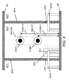
- Figure 4 shows schematically a block diagram of the filter F1 in a side view with respect to the first intersection line ISL1 shown in Figure 3 .
- the elements shown in Figure 4 that correspond to elements of the Figure 3 have been designated by the same reference numerals.
- Figure 4 shows mainly the second cavity resonator RC2 without the second resonator rod RR2 (a first part RR2-FP with a fixed length and a second resonator part RR2-AP with an adjustable length are indicated by dotted lines) and partly the first cavity resonator RC 1 on the left-hand side and partly the third cavity resonator RC3 on the right-hand side.
- the first capacitive coupling means CCM1 are mounted with equal distances to the second inner separating plate ISP2 and the third inner separating plate ISP3 at the first inner separating plate ISP1 with the first vertical coupling means height CCM1-H with respect to the inner surface of the base plate BP and with respect to a central point of the first capacitive coupling means CCM1.
- the second capacitive coupling means CCM2 are mounted with equal distances to the second inner separating plate ISP2 and the third inner separating plate ISP3 at the first inner separating plate ISP1 with the second vertical coupling means height CCM2-H with respect to the inner surface of the base plate BP and with respect to a central point of the second capacitive coupling means CCM2.
- the second vertical coupling means height CCM2-H is smaller than the first capacitive coupling means CCM1.
- one further or several further capacitive coupling means are mounted with equal distances to the second inner separating plate ISP2 and the third inner separating plate at the first inner separating plate ISP1 with one further or several further vertical coupling means heights with respect to the inner surface of the base plate BP and with respect to a central point of the one further or the several further capacitive coupling means.
- two further or more than two further capacitive coupling means are mounted symmetrically and side by side with one or several predefined intermediate distances at the first inner separating plate ISP1 with one further vertical coupling means height with respect to the inner surface of the base plate BP and with respect to a central point of the two further or the more than two further capacitive coupling means.
- Two further capacitive coupling means may be for example mounted symmetrically and side by side with a predefined intermediate distance between the first and the second capacitive coupling means CCM1, CCM2.
- Figure 4 shows a second intersection line ISL2 for a second section view shown in Figure 5 and a third intersection line ISL3 for a third section view shown in Figure 8 .
- Figure 5 shows schematically a block diagram of the filter F1 in the second section view with respect to the second intersection line ISL2 shown in Figure 3 .
- the elements shown in Figure 5 that correspond to elements of the Figure 3 and/or Figure 4 have been designated by the same reference numerals.
- the second resonator rod RR2 extends upwards from the base plate BP within the second cavity resonator RC2 and comprises the first part RR2-FP with the fixed length and the second resonator part RR2-AP with the adjustable length.
- the fifth resonator rod RR5 extends upwards from the base plate BP within the fifth cavity resonator RC5 and comprises a first part RR5-FP with a fixed length and a second part RR5-AP with an adjustable length.
- An overall length of the fixed length and the adjustable length of the resonator rods RR2, RR5 determine a resonator frequency.
- the overall length of the resonator rods RR2, RR5 is adjusted for each centre frequency of the passband to a quarter of a wavelength with respect to the centre frequency.
- the overall length is slightly smaller than the quarter of the wavelength because of a so-called end effect known to a person skilled in the art.
- a maximum of the electrical field within the cavity resonators RC2, RC5 is at a top level of the resonator rods RR2, RR5.
- the lengths of the second and fifth resonator rod RR2, RR5 are adjustable between a minimum length RR-MIN related to an upper limit of a predefined frequency tuning range and a maximum length RR-MAX related to a lower limit of the predefined frequency tuning range.
- the first and second vertical coupling means heights CCM1-H, CCM2-H are adapted to and depend on the minimum length RR-MIN and the maximum length RR-MAX and further depend on a gradient and strength of the electrical field near by the first inner separating plate ISP1.
- the first and second vertical coupling means heights CCM1-H, CCM2-H can be obtained for example by performing iterative simulations with a target to obtain a frequency independent filter bandwidth for the bandpass filter between the lower and the upper limit of the predefined frequency range.
- Figure 5 further indicates a cut-out CO, which is shown enlarged in Figure 6 .
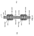
- Figure 6 shows schematically a block diagram of the cut-out CO of the first section view of Figure 5 of the filter F1 drawn to a larger scale.
- the first capacitive coupling means CCM1 preferably comprises a first disk MD1-CCM1 of an electroconductive material located within the second cavity resonator RC2, a second disk MD2-CCM1 of the electroconductive material located within the fifth cavity resonator RC5 and an electrical conductor SC-CCM1 providing an electrical contact between the first disk MD1-CCM1 and the second disk MD2-CCM1 of the first capacitive coupling means CCM1.
- the second capacitive coupling means CCM2 preferably comprises a first disk MD1 -CCM2 of the electroconductive material located within the second cavity resonator RC2, a second disk MD2-CCM2 of the electroconductive material located within the fifth cavity resonator RC5 and an electrical conductor SC-CCM2 providing an electrical contact between the first disk MD1-CCM2 and the second disk MD2-CCM2 of the second capacitive coupling means CCM1.
- the disks MD1-CCM1, MD2-CCM1, MD1-CCM2 and MD2-CCM2 are circular disks.
- the electroconductive material is for example a metallic material such as copper, aluminium, brass.
- the electroconductive material may be electro-plated plastics.
- Inner diameters of the electrical conductors SC-CCM1, SC-CCM2 are smaller than diameters of the sixth opening OP6 and a ninth opening OP9 for the second capacitive coupling means CCM2. Furthermore, the electrical conductors SC-CCM1, SC-CCM2 are centrally located with the openings OP6, OP9. These both features allow for an electrical insulation of the electrical conductors SC-CCM1, SC-CCM2 with respect to the first inner separating plate ISP1.
- the first capacitive coupling means CCM1 preferably comprises a first flat washer (NS1-CCM1 of an insulating material located between the first disk MD1 -CCM1 and the first inner separating plate ISP1 and a second flat washer INS2-CCM1 of the insulating material located between the second disk MD2-CCM1 and the first inner separating plate ISP1 providing an electrical insulation of the disks MD1 -CCM1, MD2-CCM1 with respect to the first inner separating plate ISP1.
- the second capacitive coupling means CCM2 preferably comprises a first flat washer INS1 -CCM2 of the insulating material located between the first disk MD1 -CCM2 and the first inner separating plate ISP1 and a second flat washer INS2-CCM2 of the insulating material located between the second disk MD2-CCM2 and the first inner separating plate ISP1 providing the electrical insulation of the disks MD1 -CCM2, MD2-CCM2 with respect to the first inner separating plate ISP1.
- the disks MD1-CCM1, MD2-CCM2, MD1-CCM2, MD2-CCM2 may comprise on one side directed away from the first inner separating plate ISP1 outer rounded edges as shown in Figure 6 .
- the outer rounded edges allow for a larger radio frequency power handling.
- the disks MD1-CCM1, MD2-CCM2, MD1-CCM2, MD2-CCM2 may further comprise on an outside a recess.
- the recess can be used for centring of the disks MD1 -CCM1, MD2-CCM2, MD1 -CCM2, MD2-CCM2 with respect to the opening OP6.
- the electrical conductors SC-CCM1, SC-CCM2 are preferably screw couplings for mounting the disks MD1 -CCM1, MD2-CCM2, MD1 -CCM2, MD2-CCM2 and the flat washers INS1 -CCM1 , INS2-CCM1, INS1 -CCM2, IN52-CCM2 at the first inner separating plate 1SP1.
- Screw heads of the screw couplings may fit into the recesses of the disks MD 1-CCM1, MD2-CCM2, MD1 -CCM2, MD2-CCM2.
- An extension of the diameter of the disks MD1-CCM1, MD2-CCM2, MD1-CCM2, MD2-CCM2 parallel to a surface of the first inner separating plate ISP1 and a geometrical form of the disks MD1-CCM1, MD2-CCM2, MD1 - CCM2, MD2-CCM2 may be adapted to and depend on the minimum length RR-MIN and the maximum length RR-MAX.
- a suitable extension of the diameter of the disks MD1-CCM1, MD2-CCM2, MD1-CCM2, MD2-CCM2 and a suitable geometrical form of the disks MD1-CCM1, MD2-CCM2, MD1-CCM2, MD2-CCM2 can be obtained for example by performing iterative simulations with a target to obtain a frequency independence of the frequency selectivity and the frequency distance of the notches with respect to the centre frequency between the lower and the upper limit of the predefined frequency range.
- the disks MD1-CCM1, MD2-CCM2, MD1-CCM2, MD2-CCM2 may have for example a quadratic or rectangular form but with a lower power handling in comparison to the disks MD1-CCM1, MD2-CCM2, MD1-CCM2, MD2-CCM2 having a circular form.
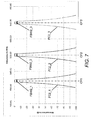
- Figure 7 shows schematically a spectral characteristic of a filter comprising the first and the second capacitive coupling means CCM1, CCM2 for adjusting the direct coupling or adjacent coupling between adjacent cavity resonators according to a further embodiment of the invention.
- the spectral characteristic relates to a so-called Chebyshev filter without any cross couplings.
- Filter bandwidths FBW2_1, FBW2_2, FBW2_3 are shown exemplarily as filter bandwidths at an attenuation value of -3 dB with respect to a maximum power throughput at the centre frequencies CF1, CF2, CF3.
- the spectral characteristic of the bandpass filter does not show any change in the filter bandwidths FBW2_1, FBW2_2, FBW2_3 for an increasing tuning frequency. This allows for a frequency independent filter bandwidth for all center frequencies within the predefined filter tuning range.
- Figure 8 shows schematically a block diagram of the filter F1 in the third section view with respect to the third intersection line ISL3 shown in Figure 3 .
- the elements shown in Figure 8 that correspond to elements of the Figure 3 , Figure 4 , Figure 5 and/or Figure 4 have been designated by the same reference numerals.
- the first electroconductive loop EL1 extends from the second cavity resonator RC2 to the fifth cavity resonator RC5 using the fifth opening OP5.
- the first electroconductive loop EL1 comprises a head piece HP-EL1 aligned parallel to the surface of the base plate BP and vertically aligned to the surface of the first inner separating plate ISP1, a first rod ST1 -EL2 vertically mounted to the head piece HP-EL1 by pressing an end piece of the first rod ST1-EL1 into an opening of the head piece HP-EL1 and a second vertical rod ST2-EL2 vertically mounted to the head piece HP-EL1 by pressing an end piece of the second rod ST2-EL2 in a further opening of the head piece HP-EL1.
- the first vertical rod ST1-EL1 penetrates the base plate BP and is partly located within the second cavity resonator RC2.
- the second vertical rod ST2-EL1 penetrates the base plate BP and is partly located within the fifth cavity resonator RC5.
- An immersion depth ID of the first electroconductive loop EL1 between the inner surface of the base plate BP and an upper surface of the head piece HP-EL1 is adjustable by moving the first and the second rod ST1-EL1, ST2-EL1 vertically to the base plate BP.
- the first and the second rod ST1 -EL1, ST2-EL1 are locked into position by using fixing sockets F51-EL1, FS2-EL2 in openings of the base plate BP, wherein the fixing sockets FS1-EL1, FS2-EL2 are plugged on the first and the second vertical rod ST1-EL, ST2-EL.
- the adjustable first electroconductive loop EL1 is preferably used to further adjust the cross coupling between the second and the fifth cavity resonator RC2, RC5 for obtaining a frequency independent filter selectivity within the predefined frequency tuning range.
- first and the second vertical coupling means heights CCM1 -H, CCM2-H and/or the size of the first and the second capacitive coupling means CCM1, CCM2 and/or the geometrical form of the first and the second capacitive coupling means CCM1, CCM2 may be adapted to the immersion depth ID of the first electroconductive loop EL1 and/or to a vertical length of the first electroconductive loop EL1 with respect to the first inner separating plate ISP1 and/or to a vertical width of the first electroconductive loop EL1 with respect to the second and the third inner separating plates ISP2, ISP3 and/or to a geometrical form of the first electroconductive loop EL1.
- a combined use of the first and the second capacitive coupling means CCM1, CCM2 and the first electroconductive loop EL1 at the inner separating plate ISP1 between the second cavity resonator RC2 and the fifth cavity resonator RC5 allows for an adjustable and frequency independent cross coupling between the second cavity resonator RC2 and the fifth cavity resonator RC5.
Landscapes
- Physics & Mathematics (AREA)
- Electromagnetism (AREA)
- Control Of Motors That Do Not Use Commutators (AREA)
Abstract
Description
- The invention relates to a filter for radio frequency signals and, more particularly but not exclusively, to a bandpass filter comprising a plurality of coaxial air cavity resonators.
- A radio frequency spectral range is split into several sub-ranges for different wireless communication technologies such as radio broadcasting, mobile radio communication or satellite communication or is split into several sub-ranges for a same wireless communication technology but for different operators providing the same wireless communication technology. Bandpass filters are used for example in radio communication systems to keep radio frequency signals within a specific radio frequency sub-range for avoiding interference and/or noise in neighbouring radio frequency sub-ranges or for keeping the interference and/or the noise below specific thresholds, which may depend on legal requirements or on wireless communication specifications.
- Tunable bandpass filters are preferably used for filtering RF signals (RF = radio frequency) in comparison to bandpass filters with fixed filtering properties, especially due to manufacturing and storage costs and flexibility in use.
- Characteristics of the bandpass filter such as a maximum allowed deviation from a required frequency bandwidth or a minimum required signal suppression for example in dB outside a passband of the bandpass filter irrespective of a centre frequency of the passband within a specified filter tuning range are major design criteria for bandpass filters having to fulfil a frequency independent selectivity mask over the specified filter tuning range.
- Due to the nature of electromagnetic coupling structures within a bandpass filter having an electromagnetic coupling of present state of the art, the characteristics of the bandpass filter are usually frequency dependent and may not fulfil specific legal emission requirements or wireless communication specifications over a predefined frequency tuning range.
- If the filter comprises for example coaxial air cavity resonators with enclosed hollow spaces as an outer conductor and with length adjustable resonator rods as inner conductors, the filter can be tuned to another frequency by adjusting a length of the resonator rods.
- If a bandpass filter of the present state of the art is tuned to a lower centre frequency and a same filter mask has to be applied at the lower centre frequency, then the filter bandwidth would decrease and a passband part of the filter curve cannot exceed a first threshold of the filter mask for a first predefined frequency range according to different centre frequencies of the predefined frequency tuning range. Similarly, if the bandpass filter of the present state of the art is tuned to a higher centre frequency and a same filter mask has to be applied at the higher centre frequency, then the filter bandwidth would increase and the filter curve cannot fall below second and third thresholds of the filter mask for second and third predefined frequency ranges according to further different centre frequencies of the predefined frequency tuning range.
- Such behaviour is mainly based on a length change of the resonator rods generating a frequency dependent coupling between the resonators of the filter and thereby causing a frequency dependence in a width of the passband and in a frequency selectivity of the filter.
- The way of fulfilling spectral requirements of filter masks over a predefined filter tuning range affects the spectral characteristic of the filter.
- Therefore, it is an object of the invention to provide an improved filter for radio frequency signals with a frequency independent spectral characteristic for all centre frequencies within a predefined filter tuning range.
- The object is achieved by a filter for radio frequency signals comprising a first cavity resonator, a second cavity resonator and an inner separating plate separating the first cavity resonator and the second cavity resonator and extending upwards from a base plate. The filter further comprises a first capacitive coupling means penetrating the inner separating plate at a first height level with respect to the base plate and a second capacitive coupling means penetrating the inner separating plate at a second height level with respect to the base plate.
- The filter may be a bandpass filter and the at least two cavity resonators may be coaxial transverse electromagnetic wave mode resonators.
- The invention has a first benefit of providing a frequency independent width of the passband of the filter and a frequency independent selectivity over a predefined frequency tuning range. A frequency independent bandwidth is linked to a frequency independent selectivity especially in case of a Chebyshev filter.
- The invention provides a second benefit of allowing for an easy tuning process not requiring an adjustment of adjustment means even more complex than adjustable coupling loops for getting a same bandpass filter bandwidth for different center frequencies within the predefined filter tuning range.
- The invention provides a third benefit of lowering manufacturing and storage costs, because a same bandpass filter type can be used for many applications and different center frequencies with a same spectral quality.
- In a preferred embodiment of the invention, the first capacitive coupling means is arranged vertically on top of the second capacitive coupling means with respect to the base plate and the first capacitive coupling means and the second coupling means are arranged with a same distance to further inner separating plates between the first or the second cavity resonator and further cavity resonators of the filter. This arrangement provides a strongest effect of keeping a coupling between the first and the second cavity resonator frequency independent over the predefined frequency tuning range.
- In a further embodiment of the invention, at least a third capacitive coupling means penetrates the inner separating plate between the first height level and the second height level. This allows for more flexibility in obtaining a frequency independent spectral characteristic of the filter over a predefined frequency tuning range.
- According to an even further embodiment of the invention, at least two further capacitive coupling means penetrate the inner separating plate at a same height level with respect to the base plate. This also provides a possibility for optimizing a frequency independence of the spectral characteristic of the filter over a predefined frequency tuning range.
- In a further preferred embodiment of the invention, the filter further comprises a first resonator rod extending upwards from the base plate within the first cavity resonator and a second resonator rod extending upwards from the base plate within the second cavity resonator, lengths of the first and the second resonator rod are adjustable between a minimum length for an upper limit of a predefined frequency tuning range and a maximum length for a lower limit of the predefined frequency tuning range and the at least two different height levels of the first and the second capacitive coupling means depend on the minimum and the maximum length.
- This allows applying the invention preferably to filters comprising length adjustable resonator rods for tuning the filter.
- In a further embodiment of the invention, a first size and/or a first geometrical form of the first capacitive coupling means extending into the first cavity resonator and a second size and/or a second geometrical form of the second capacitive coupling means extending into the second cavity resonator are equal or different. This offers a benefit of not limiting an arrangement of the capacitive coupling means according to the heights but also adapting the size and/or the geometrical form of the first and the second capacitive coupling means in a same or different manner for a frequency independent electromagnetic coupling. This allows for a larger flexibility in simulations for choosing in addition to adequate heights also adequate sizes and forms for the first and the second capacitive coupling means for a frequency independent coupling over a predefined frequency range.
- According to a preferred embodiment of the invention, the first and the second capacitive coupling means comprise first disks of an electroconductive material within the first cavity resonator and second disks of the electroconductive material within the second cavity resonator and wherein the first and the second disks are centrally connected with an electrical conductor.
- Preferably, the first and the second disks are circular. This provides a benefit of a uniform distribution of the electrical field within the first and the second disks.
- According to a further preferred embodiment of the invention, the electrical conductor is a screw coupling. This provides an advantage of using a centre part of the capacitive coupling means also as a mounting material for mounting the first and second capacitive coupling means at the inner separating plate and thereby not requiring any additional mounting material. This allows further cost saving.
- The first and the second capacitive coupling means are electrically isolated with respect to the inner separating plate. Thereby, a short-circuit is avoided and a capacitive coupling between the first and the second cavity resonator can be provided.
- According to an even further preferred embodiment of the invention, the filter further comprises first flat washers of an electrically insulating material between first ends of the first and the second capacitive coupling means and the inner separating plate and second flat washers of the electrically insulating material between second ends of the first and the second capacitive coupling means and the inner separating plate. This provides a first benefit of an increased mechanical stability according to vibrations. This provides a second benefit of an increased power handling and long-term stability of the filter.
- Preferably, the electrically insulating material is Teflon. This provides an advantage of using advantageous features of Teflon such as low-loss and sufficient stiffness for high power applications.
- In a further preferred embodiment of the invention, the filter further comprises an electroconductive coupling loop penetrating the inner separating plate from the first cavity resonator to the second cavity resonator.
- The alternative embodiment of the invention provides a benefit of using the electroconductive coupling loop within an opening of the inner separating plate for an adjustment of the capacitive coupling between the first and the second cavity resonator. The adjustment allows for an improved frequency independence of the bandpass filter curve at different centre frequencies within the predefined frequency range or allows to increase the frequency range with frequency dependence below a predefined threshold. Preferably, the electroconductive coupling loop is adjustable by an immersion depth towards the first and the second cavity resonator with respect to the base plate.
- This allows for an external adjustment of the immersion depth and low costs not requiring opening the housing of the filter.
- According to a further alternative embodiment of the invention, the first and the second height level, the first size and/or the first geometrical form of the first capacitive coupling means and the second size and/or the second geometrical form of the second capacitive coupling means are adapted to an immersion depth, a size and/or a geometrical form of the electroconductive coupling loop. This provides an advantage of adapting geometrical parameters of the first and the second capacitive coupling means for example by simulations to geometrical parameters of the electroconductive coupling loop for a frequency independent inductive coupling between the first and the second resonator using the electroconductive coupling loop.
- In a further preferred embodiment of the invention, the filter further comprises a second electroconductive coupling loop penetrating a second inner separating plate between the first cavity resonator and a further cavity resonator and a third electroconductive coupling loop penetrating a third inner separating plate between the second cavity resonator and an even further cavity resonator and the second electroconductive coupling loop and the third electroconductive coupling loop are located with a first distance to outer walls of the filter and with a second distance to the inner separating plate and the first distance is smaller than the second distance. This provides a benefit of optimizing a frequency independence of the spectral characteristic of the filter over a predefined frequency tuning range by selecting same or different adequate positions for the second electroconductive coupling loop and the the third electroconductive coupling loop with respect to the outer walls and the inner separating plate. In a further preferred embodiment of the invention, the second distance is in a range between a threefold and fourfold of the first distance. A more specific range for the second distance depends on required coupling values for the filter with respect to fulfilling a specific filter mask over a predefined frequency tuning range. This provides an advantage of allowing for an easier manufacturing process of hollow spaces required for the cavity resonators and of openings within inner separating walls required for the second and the third electroconductive coupling loop by applying a milling process in a single direction. If the second electroconductive coupling loop and the third electroconductive coupling loop would be located with equal values for the first and the second distance a milling process for the openings of the second and the third electroconductive coupling loop would require a further milling step in a further direction perpendicular to the milling process for the hollow spaces of the cavity resonators. Therefore, manufacturing costs can be reduced.
- Further advantageous features of the invention are defined and are described in the following detailed description of the invention.
- The embodiments of the invention will become apparent in the following detailed description and will be illustrated by accompanying figures given by way of non-limiting illustrations.
-
Figure 1 shows schematically a spectral characteristic of a Chebyshev type bandpass filter of the present art at three different centre frequencies. -
Figure 2 shows schematically spectral characteristics of a quasi-elliptic bandpass filter and a filter mask at a single centre frequency. -
Figure 3 shows schematically a block diagram of a filter in a top view according an embodiment of the invention. -
Figure 4 shows schematically a block diagram of a portion of the filter in a side view. -
Figure 5 shows schematically a block diagram of the filter in a first section view. -
Figure 6 shows schematically a block diagram of a section of the filter in the first section view drawn to a larger scale. -
Figure 7 shows schematically a spectral characteristic of a filter according to a further embodiment of the invention at three different centre frequencies. -
Figure 8 shows schematically a block diagram of the filter in a second section view. -
Figure 1 shows schematically a spectral characteristic of a Chebyshev type bandpass filter of the present art at three different centre frequencies. Three different fitter curves FC1_1, FC1_2, FC1_3 are shown as a function of frequency at three different centre frequencies CF1, CF2,CF3 1 and exhibit increasing filter bandwidths FBW1_1, FBW1_2, FBW1_3 with increasing tuning frequency. The filter bandwidths FBW1_1, FBW1_2, Few1_3 are shown exemplarily as filter bandwidths at an attenuation value of -3 dB with respect to a minimum attenuation (maximum power throughput) at the centre frequencies CF1, CF2, CF3. Such a frequency dependent filter characteristic may not fulfil specific legal emission requirements or wireless communication specifications for all centre frequencies within a predefined frequency tuning range. -
Figure 2 shows exemplarily a filter curve FC of a bandpass filter around a centre frequency CF as a function of frequency.Figure 2 further shows a curve of a filter mask with a first part SPEC1 around the centre frequency CF, with further parts SPEC2, SPEC3, SPEC4 at lower frequencies and with even further parts SPEC5, SPEC6, SPEC7 at higher frequencies. The bandpass filter is optimized with sufficient small unbalance for a given centre frequency in such a way, that the filter curve FC exceeds a first threshold of the first part SPEC1 around the centre frequency CF and falls below thresholds of further parts SPEC2 to SPEC7 at the lower and the higher frequencies with respect to the curve of the filter mask. If a bandpass filter of the present art is tuned to another centre frequency requirements of the filter mask may not be fulfilled. -
Figure 3 shows schematically in a block diagram and a top view a filter F1 according to a preferred embodiment of the invention. The detailed structure of the filter F1 is not critical, and as can be understood by those skilled in the art, that the detailed structure of the filter F1 may vary without departing from the scope of the invention. - The filter F1 may be a band-pass filter for radio frequency signals of a broadcasting service and may be applied in a transmission path of a base station of a network of a broadcasting service provider. The filter F1 may be for example a high-power radio broadcasting filter adapted to a frequency band with a frequency tuning range between 470 MHz and 860 MHz. Alternatively, the filter F1 may be applied in a transmission and/or reception path of a base station of a mobile radio network using a radio access technology such as GSM/GPRS (GSM = Global System for Mobile Communication, GPRS = General Packet Radio Service), UMTS (UMTS = Universal Mobile Telecommunication Systems), or LTE (LTE = Long Term Evolution). Therefore, the filter F1 may be for example adapted to 900 MHz or 1800 MHz frequency bands of GSM or to frequency bands specified for UMTS, WiMAX (WiMAX = Worldwide Interoperability for Microwave Access), and/or LTE.
- The filter F1 may comprise a first cavity resonator RC1, a second cavity resonator RC2, a third cavity resonator RC3, a fourth cavity resonator RC4, a fifth cavity resonator RC5 and a sixth cavity resonator RC6 arranged in a U-shaped order with a U-shaped resonator path as indicated in
Figure 3 by an arrow AR. The cavity resonators RC1 to RC6 may be coaxial transverse electromagnetic wave mode resonators and may have identical geometrical dimensions. - Alternatively, the filter may comprise less than six cavity resonators or more than six cavity resonators.
- In a further alternative, the cavity resonators may be arranged in a linear or straight form.
- In even further alternatives, the cavity resonators may be arranged in an S-shaped order or an arrangement of the cavity resonators may comprise a combination of cavity resonators in a U-shaped order and of further cavity resonators in an S-shaped order.
- The filter F1 comprises a first port PORT1 for coupling the radio frequency signals into the filter F1 and comprises a second port PORT2 for outcoupling the radio frequency signals from the filter F1.
- The ports PORT1, PORT2 may be for example coaxial ports with a central inner and an outer conductor.
- Openings within a first outer wall OW1 of a housing of the filter F1 between the first port PORT1 and the first cavity resonator RC1 and between the second port PORT2 and the sixth cavity resonator RC6 are not shown for simplification.
- The housing of the filter F1 is shown in
Figure 3 without a cover plate to be able to see the interior parts of the filter F1. - The housing comprises a base plate BP, the first outer wall OW1, a second outer wall OW2, a third outer wall OW3, a fourth outer wall OW4, a first inner separating wall ISP1, a second inner separating wall ISP2, a third inner separating wall ISP3, a fourth inner separating wall ISP4, a fifth inner separating wall ISP5, a sixth inner separating wall ISP6 and a seventh inner separating wall ISP7. Resonator rods RR1, RR2, RR3, RR4, RR5, RR6 are located centrally within the cavity resonators RC1 to RC6 and are extending upwards from the base plate BP.
- The housing of the filter F1 is used as an outer conductor and the resonator rods RR1 to RR6 are used as inner conductors. The base plate BP, the outer walls OW1 to OW4, the inner separating walls ISP1 to ISP7 and the cover plate partly (because the cover plate is not shown) form separate hollow spaces for the cavity resonators RC1 to RC6.
- The filter F1 further comprises a first coupling loop STR1 in a first opening OP1 of the second inner separating wall ISP2 between the first cavity resonator RC1 and the second cavity resonator RC2, a second coupling loop STR2 in a second opening OP2 of the third inner separating wall ISP3 between the second cavity resonator RC2 and the third cavity resonator RC3, a third coupling loop STR3 in a seventh opening OP7 of the fourth inner separating wall ISP4 between the third cavity resonator RC3 and the fourth cavity resonator RC4, a fourth coupling loop STR4 in a third opening OP3 of the fifth inner separating wall ISP5 between the fourth cavity resonator RC4 and the fifth cavity resonator RC5 and a fifth coupling loop STR5 in a fourth opening OP4 of the sixth inner separating wall ISP6 between the fifth cavity resonator RC5 and the sixth cavity resonator RC6. The coupling loops STR1 to STR5 are used for direct inductive electromagnetic couplings between adjacent cavity resonators in a direction of the arrow AR and have preferably externally adjustable immersion depths.
- In a preferred embodiment, the first and the second coupling loops STR1, ST2 are located with a first distance D1 to the fourth outer wall OW4 of the filter F1 and with a second distance D2 to the first inner separating plate ISPI and the first distance D1 is smaller than the second distance D2. Equally, the third and the fourth coupling loops STR3, ST4 are located with the first distance D1 to the second outer wall OW2 of the filter F1 and with the second distance D2 to the first inner separating plate ISP1.
- In a further preferred embodiment of the invention as shown in
Figure 3 , the second distance D2 is in a range between a threefold and fourfold of the first distance D1. - A filter for radio frequency signals exhibits an electromagnetic coupling between adjacent cavity resonators in a direction of the resonator path such as shown by the arrow AR in
Figure 3 . This type of electromagnetic filter resonator coupling is called direct coupling or adjacent coupling between the cavity resonator pairs RC1/RC2, RC2/RC3, RC3/RC4, RC4/RC5, RC5/RC6. A specific bandwidth of the passband can be adjusted according to a specific filter mask for fulfilling the spectral requirements by adjusting the direct coupling between the cavity resonator pairs RC1/RC2, RC2/RC3, RC3/RC4, RC4/RC5, RC5/RC6. - The filter usually also exhibits a further electromagnetic coupling between cavity resonators, which are not adjacent in the direction of the resonator path. This further type of electromagnetic filter resonator coupling is referred to as cross coupling. Due to the U-shape of the resonator path of the filter F1 exemplarily shown in
Figure 3 , cross couplings exist between following pairs of cavity resonators: RC1/RC6, RC2/RC5. - Cross coupling can be used to include transmission zeros or notches in monotonous sloping filter attenuation bands besides a (transmission) passband of the bandpass filter being symmetrically arranged according to a centre frequency of the passband. The cross coupling between two cavity resonators not adjacent in the direction of the resonator path determines a frequency position and a symmetry of the notches shown for example in
Figure 2 . - Such application is known to a person skilled in the art and is therefore not further explained in the following.
- The filter F1 further comprises first capacitive coupling means CCM1 penetrating the first inner separating plate ISP1 using a sixth opening OP6 between the second and the fifth cavity resonator RC2, RC5 at a first vertical coupling means height with respect to the base plate BP and second capacitive coupling means (the second capacitive coupling means is not shown in
Figure 3 due to the top view) penetrating the first inner separating plate ISP1 using a ninth opening (not shown inFigure 3 due to the top view) between the second and the fifth cavity resonator RC2, RC5 at a second vertical coupling means height with respect to the base plate BP. The capacitive coupling means are also known as capacitive coupling probes. The first capacitive coupling means CCM1 and the second capacitive coupling means extend into the second and the fifth cavity resonator RC2, RC5 for being able to link to the electrical fields within the second and the fifth cavity resonator RC2, RC5. - The first capacitive coupling means CCM1 and the second capacitive coupling means are preferably applied for controlling the cross coupling.
- In a first alternative, two or more further capacitive coupling means may penetrate additionally into the sixth inner separating wall ISP6 using further openings at different heights with respect to the inner surface of the base plate BP.
- In a second alternative, the two or more further capacitive coupling means penetrate the sixth inner separating wall ISP6 using the further openings at the different heights instead of the first capacitive coupling means CCM1 and the second capacitive coupling means penetrating the first inner separating wall ISP1.
- In a further alternative according to a Chebyshev filter (not shown in
Figure 3 ), two or even more capacitive coupling means may penetrate at two or more heights with respect to a base plate of the Chebyshev filter an inner separating plate between two adjacent cavity resonators employing a direct coupling. In such a case, a first bandwidth of a passband of the Chebyshev filter for a first centre frequency within a predefined frequency tuning range is equal to a second bandwidth of the passband of the Chebyshev filter for a second centre frequency within a predefined frequency tuning range and the second centre frequency is different to the first centre frequency. Thereby, the bandwidth of the passband is frequency independent over the predefined frequency tuning range. - The first and the second height are chosen in such a way, that a frequency selectivity and a frequency distance of the notches with respect to the centre frequency is frequency-independent between a lower and an upper limit of a predefined frequency tuning range.
- The lower limit and the upper limit of the predefined frequency tuning range may depend on a frequency subband assigned to an operator of a broadcast service or a mobile radio service such as LTE.
- Alternatively, the lower limit and the upper limit of the predefined frequency tuning range may depend on a frequency band allocated to broadcast services or mobile radio services of several operators and wherein the frequency band may be divided into several adjacent subbands for the several operators.
- The filter F1 may further but not necessarily comprise one or several inductive coupling means forming a first electroconductive loop EL1 in a fifth opening OP5 of the first inner separating wall ISP1 for an inductive coupling between the second cavity resonator RC2 and the fifth cavity resonator RC5 and forming preferably a second electroconductive loop EL2 in an eighth opening OP8 of the sixth inner separating wall ISP6 for an inductive coupling between the first cavity resonator RC1 and the sixth cavity resonator RC6.
- Immersion depths of the first electroconductive loop EL1 and the second electroconductive loop EL2 may be adjustable for adjusting and fine tuning the cross couplings between the second cavity resonator RC2 and the fifth cavity resonator RC5 and between the first cavity resonator RC1 and the sixth cavity resonator RC6 (see also
Figure 8 ). Thereby, the position of the notches can be determined more precisely. -
Figure 3 shows a first intersection line ISL1 for a first section view shown inFigure 4 , a second intersection line ISL2 for a second section view shown inFigure 5 and a third intersection line ISL3 for a third section view shown inFigure 8 . -
Figure 4 shows schematically a block diagram of the filter F1 in a side view with respect to the first intersection line ISL1 shown inFigure 3 . The elements shown inFigure 4 that correspond to elements of theFigure 3 have been designated by the same reference numerals. -
Figure 4 shows mainly the second cavity resonator RC2 without the second resonator rod RR2 (a first part RR2-FP with a fixed length and a second resonator part RR2-AP with an adjustable length are indicated by dotted lines) and partly the firstcavity resonator RC 1 on the left-hand side and partly the third cavity resonator RC3 on the right-hand side. The first capacitive coupling means CCM1 are mounted with equal distances to the second inner separating plate ISP2 and the third inner separating plate ISP3 at the first inner separating plate ISP1 with the first vertical coupling means height CCM1-H with respect to the inner surface of the base plate BP and with respect to a central point of the first capacitive coupling means CCM1. The second capacitive coupling means CCM2 are mounted with equal distances to the second inner separating plate ISP2 and the third inner separating plate ISP3 at the first inner separating plate ISP1 with the second vertical coupling means height CCM2-H with respect to the inner surface of the base plate BP and with respect to a central point of the second capacitive coupling means CCM2. The second vertical coupling means height CCM2-H is smaller than the first capacitive coupling means CCM1. In further alternatives, one further or several further capacitive coupling means are mounted with equal distances to the second inner separating plate ISP2 and the third inner separating plate at the first inner separating plate ISP1 with one further or several further vertical coupling means heights with respect to the inner surface of the base plate BP and with respect to a central point of the one further or the several further capacitive coupling means. - In an even further alternative, two further or more than two further capacitive coupling means are mounted symmetrically and side by side with one or several predefined intermediate distances at the first inner separating plate ISP1 with one further vertical coupling means height with respect to the inner surface of the base plate BP and with respect to a central point of the two further or the more than two further capacitive coupling means. Two further capacitive coupling means may be for example mounted symmetrically and side by side with a predefined intermediate distance between the first and the second capacitive coupling means CCM1, CCM2.
-
Figure 4 shows a second intersection line ISL2 for a second section view shown inFigure 5 and a third intersection line ISL3 for a third section view shown inFigure 8 . -
Figure 5 shows schematically a block diagram of the filter F1 in the second section view with respect to the second intersection line ISL2 shown inFigure 3 . The elements shown inFigure 5 that correspond to elements of theFigure 3 and/orFigure 4 have been designated by the same reference numerals. - The second resonator rod RR2 extends upwards from the base plate BP within the second cavity resonator RC2 and comprises the first part RR2-FP with the fixed length and the second resonator part RR2-AP with the adjustable length.
- The fifth resonator rod RR5 extends upwards from the base plate BP within the fifth cavity resonator RC5 and comprises a first part RR5-FP with a fixed length and a second part RR5-AP with an adjustable length.
- Such length adjustable resonator rods are known for a person skilled in the art and are therefore not explained in more detail. An overall length of the fixed length and the adjustable length of the resonator rods RR2, RR5 determine a resonator frequency. The overall length of the resonator rods RR2, RR5 is adjusted for each centre frequency of the passband to a quarter of a wavelength with respect to the centre frequency. Usually the overall length is slightly smaller than the quarter of the wavelength because of a so-called end effect known to a person skilled in the art. A maximum of the electrical field within the cavity resonators RC2, RC5 is at a top level of the resonator rods RR2, RR5.
- The lengths of the second and fifth resonator rod RR2, RR5 are adjustable between a minimum length RR-MIN related to an upper limit of a predefined frequency tuning range and a maximum length RR-MAX related to a lower limit of the predefined frequency tuning range. The first and second vertical coupling means heights CCM1-H, CCM2-H are adapted to and depend on the minimum length RR-MIN and the maximum length RR-MAX and further depend on a gradient and strength of the electrical field near by the first inner separating plate ISP1.
- The first and second vertical coupling means heights CCM1-H, CCM2-H can be obtained for example by performing iterative simulations with a target to obtain a frequency independent filter bandwidth for the bandpass filter between the lower and the upper limit of the predefined frequency range.
-
Figure 5 further indicates a cut-out CO, which is shown enlarged inFigure 6 . -
Figure 6 shows schematically a block diagram of the cut-out CO of the first section view ofFigure 5 of the filter F1 drawn to a larger scale. - The first capacitive coupling means CCM1 preferably comprises a first disk MD1-CCM1 of an electroconductive material located within the second cavity resonator RC2, a second disk MD2-CCM1 of the electroconductive material located within the fifth cavity resonator RC5 and an electrical conductor SC-CCM1 providing an electrical contact between the first disk MD1-CCM1 and the second disk MD2-CCM1 of the first capacitive coupling means CCM1.
- Similarly, the second capacitive coupling means CCM2 preferably comprises a first disk MD1 -CCM2 of the electroconductive material located within the second cavity resonator RC2, a second disk MD2-CCM2 of the electroconductive material located within the fifth cavity resonator RC5 and an electrical conductor SC-CCM2 providing an electrical contact between the first disk MD1-CCM2 and the second disk MD2-CCM2 of the second capacitive coupling means CCM1.
- Preferably, the disks MD1-CCM1, MD2-CCM1, MD1-CCM2 and MD2-CCM2 are circular disks.
- The electroconductive material is for example a metallic material such as copper, aluminium, brass. In a further alternative, the electroconductive material may be electro-plated plastics.
- Inner diameters of the electrical conductors SC-CCM1, SC-CCM2 are smaller than diameters of the sixth opening OP6 and a ninth opening OP9 for the second capacitive coupling means CCM2. Furthermore, the electrical conductors SC-CCM1, SC-CCM2 are centrally located with the openings OP6, OP9. These both features allow for an electrical insulation of the electrical conductors SC-CCM1, SC-CCM2 with respect to the first inner separating plate ISP1.
- In a further preferred embodiment as shown in
Figure 6 , the first capacitive coupling means CCM1 preferably comprises a first flat washer (NS1-CCM1 of an insulating material located between the first disk MD1 -CCM1 and the first inner separating plate ISP1 and a second flat washer INS2-CCM1 of the insulating material located between the second disk MD2-CCM1 and the first inner separating plate ISP1 providing an electrical insulation of the disks MD1 -CCM1, MD2-CCM1 with respect to the first inner separating plate ISP1. - Equally, the second capacitive coupling means CCM2 preferably comprises a first flat washer INS1 -CCM2 of the insulating material located between the first disk MD1 -CCM2 and the first inner separating plate ISP1 and a second flat washer INS2-CCM2 of the insulating material located between the second disk MD2-CCM2 and the first inner separating plate ISP1 providing the electrical insulation of the disks MD1 -CCM2, MD2-CCM2 with respect to the first inner separating plate ISP1.
- The insulating material may be for example Teflon, Rexolite (is a cross linked polystyrene microwave plastic), or a suitable PVC material (PVC = polyvinyl chloride).
- The disks MD1-CCM1, MD2-CCM2, MD1-CCM2, MD2-CCM2 may comprise on one side directed away from the first inner separating plate ISP1 outer rounded edges as shown in
Figure 6 . The outer rounded edges allow for a larger radio frequency power handling. - The disks MD1-CCM1, MD2-CCM2, MD1-CCM2, MD2-CCM2 may further comprise on an outside a recess. The recess can be used for centring of the disks MD1 -CCM1, MD2-CCM2, MD1 -CCM2, MD2-CCM2 with respect to the opening OP6.
- The electrical conductors SC-CCM1, SC-CCM2 are preferably screw couplings for mounting the disks MD1 -CCM1, MD2-CCM2, MD1 -CCM2, MD2-CCM2 and the flat washers INS1 -CCM1 , INS2-CCM1, INS1 -CCM2, IN52-CCM2 at the first inner separating plate 1SP1.
- Screw heads of the screw couplings may fit into the recesses of the disks MD 1-CCM1, MD2-CCM2, MD1 -CCM2, MD2-CCM2.
- An extension of the diameter of the disks MD1-CCM1, MD2-CCM2, MD1-CCM2, MD2-CCM2 parallel to a surface of the first inner separating plate ISP1 and a geometrical form of the disks MD1-CCM1, MD2-CCM2, MD1 - CCM2, MD2-CCM2 may be adapted to and depend on the minimum length RR-MIN and the maximum length RR-MAX. A suitable extension of the diameter of the disks MD1-CCM1, MD2-CCM2, MD1-CCM2, MD2-CCM2 and a suitable geometrical form of the disks MD1-CCM1, MD2-CCM2, MD1-CCM2, MD2-CCM2 can be obtained for example by performing iterative simulations with a target to obtain a frequency independence of the frequency selectivity and the frequency distance of the notches with respect to the centre frequency between the lower and the upper limit of the predefined frequency range. The disks MD1-CCM1, MD2-CCM2, MD1-CCM2, MD2-CCM2 may have for example a quadratic or rectangular form but with a lower power handling in comparison to the disks MD1-CCM1, MD2-CCM2, MD1-CCM2, MD2-CCM2 having a circular form.
-
Figure 7 shows schematically a spectral characteristic of a filter comprising the first and the second capacitive coupling means CCM1, CCM2 for adjusting the direct coupling or adjacent coupling between adjacent cavity resonators according to a further embodiment of the invention. The spectral characteristic relates to a so-called Chebyshev filter without any cross couplings. - Three different filter curves FC2_1, FC2_2, FC2_3 are shown as a function of frequency at the same centre frequencies CF1, CF2, CF3 as shown in
Figure 1 . Filter bandwidths FBW2_1, FBW2_2, FBW2_3 are shown exemplarily as filter bandwidths at an attenuation value of -3 dB with respect to a maximum power throughput at the centre frequencies CF1, CF2, CF3. - Using the present invention the spectral characteristic of the bandpass filter does not show any change in the filter bandwidths FBW2_1, FBW2_2, FBW2_3 for an increasing tuning frequency. This allows for a frequency independent filter bandwidth for all center frequencies within the predefined filter tuning range.
-
Figure 8 shows schematically a block diagram of the filter F1 in the third section view with respect to the third intersection line ISL3 shown inFigure 3 . The elements shown inFigure 8 that correspond to elements of theFigure 3 ,Figure 4 ,Figure 5 and/orFigure 4 have been designated by the same reference numerals. - The first electroconductive loop EL1 extends from the second cavity resonator RC2 to the fifth cavity resonator RC5 using the fifth opening OP5. The first electroconductive loop EL1 comprises a head piece HP-EL1 aligned parallel to the surface of the base plate BP and vertically aligned to the surface of the first inner separating plate ISP1, a first rod ST1 -EL2 vertically mounted to the head piece HP-EL1 by pressing an end piece of the first rod ST1-EL1 into an opening of the head piece HP-EL1 and a second vertical rod ST2-EL2 vertically mounted to the head piece HP-EL1 by pressing an end piece of the second rod ST2-EL2 in a further opening of the head piece HP-EL1.
- The first vertical rod ST1-EL1 penetrates the base plate BP and is partly located within the second cavity resonator RC2. Similarly, the second vertical rod ST2-EL1 penetrates the base plate BP and is partly located within the fifth cavity resonator RC5.
- An immersion depth ID of the first electroconductive loop EL1 between the inner surface of the base plate BP and an upper surface of the head piece HP-EL1 is adjustable by moving the first and the second rod ST1-EL1, ST2-EL1 vertically to the base plate BP. The first and the second rod ST1 -EL1, ST2-EL1 are locked into position by using fixing sockets F51-EL1, FS2-EL2 in openings of the base plate BP, wherein the fixing sockets FS1-EL1, FS2-EL2 are plugged on the first and the second vertical rod ST1-EL, ST2-EL.
- The adjustable first electroconductive loop EL1 is preferably used to further adjust the cross coupling between the second and the fifth cavity resonator RC2, RC5 for obtaining a frequency independent filter selectivity within the predefined frequency tuning range.
- In an alternative embodiment, the first and the second vertical coupling means heights CCM1 -H, CCM2-H and/or the size of the first and the second capacitive coupling means CCM1, CCM2 and/or the geometrical form of the first and the second capacitive coupling means CCM1, CCM2 may be adapted to the immersion depth ID of the first electroconductive loop EL1 and/or to a vertical length of the first electroconductive loop EL1 with respect to the first inner separating plate ISP1 and/or to a vertical width of the first electroconductive loop EL1 with respect to the second and the third inner separating plates ISP2, ISP3 and/or to a geometrical form of the first electroconductive loop EL1.
- A combined use of the first and the second capacitive coupling means CCM1, CCM2 and the first electroconductive loop EL1 at the inner separating plate ISP1 between the second cavity resonator RC2 and the fifth cavity resonator RC5 allows for an adjustable and frequency independent cross coupling between the second cavity resonator RC2 and the fifth cavity resonator RC5.
Claims (9)
- A filter (F1) for radio frequency signals comprising a first cavity resonator (RC2), a second cavity resonator (RC5), an inner separating plate (ISP1) separating said first cavity resonator (RC2) and said second cavity resonator (RC5) and extending upwards from a base plate (BP), a first capacitive coupling means (CCM1) penetrating said inner separating plate (ISP1) at a first height level (CCM1 -H) with respect to said base plate (BP) and a second capacitive coupling means (CCM2) penetrating said inner separating plate (ISP1) at a second height level (CCM2-H) with respect to said base plate (BP).
- Filter (F1) according to claim 1, wherein said filter (F1) further comprises an electroconductive coupling loop (EL1) penetrating said inner separating plate (ISP1) from said first cavity resonator (RC2) to said second cavity resonator (RC5).
- Filter (F1) according to any of the preceding claims, wherein said filter (F1) further comprises a second electroconductive coupling loop (STR1, STR2) penetrating a second inner separating plate (ISP2, ISP3) between said first cavity resonator (RC2) and a further cavity resonator (RC1, RC3) and a third electroconductive coupling loop (STR3, STR4) penetrating a third inner separating plate (ISP5, ISP6) between said second cavity resonator (RC5) and an even further cavity resonator (RC4, RC6), wherein said second electroconductive coupling loop (STR1, STR2) and said third electroconductive coupling loop (STR3, STR4) are located with a first distance (D1) to outer walls (OW2, OW4) of said filter (F1) and with a second distance (D2) to said inner separating plate (ISP1) and wherein said first distance (D1) is smaller than said second distance (D2).
- Filter (F1) according to any of the preceding claims, wherein said first capacitive coupling means (CCM1) is arranged vertically on top of said second capacitive coupling means (CCM2) with respect to said base plate (BP) and wherein said first capacitive coupling means (CCM1) and said second coupling means (CCM2) are arranged with a same distance to inner separating plates (ISP2, ISP3, ISP5, ISP6) between said first cavity resonator (RC2, RC5) and further cavity resonators (RC1, RC3) of the filter (F1) or between said second cavity resonator (RC2, RC5) and even further cavity resonators (RC4, RC6) of the filter (F1).
- Filter (F1) according to any of the preceding claims, wherein said first and said second capacitive coupling means (CCM1, CCM2) are applied for an electromagnetic cross coupling or an electromagnetic direct coupling between said first cavity resonator (RC2) and said second cavity resonator (RC5).
- Filter (F1) according to any of the preceding claims, wherein said filter (F1) further comprises a first resonator rod (RR1) extending upwards from said base plate (BP) within said first cavity resonator (RC2) and a second resonator rod (RR2) extending upwards from said base plate (BP) within said second cavity resonator (RC5), wherein lengths of said first and said second resonator rod (RR1, RR2) are adjustable between a minimum length (RR-MIN) for an upper limit of a predefined frequency tuning range and a maximum length (RR-MAX) for a lower limit of said predefined frequency tuning range and wherein said first and said second height level (CCM1-H, CCM2-H) of said first and said second capacitive coupling means (CCM1, CCM2) depend on said minimum and said maximum length (RR-MIN, RR-MAX).
- Filter (F1) according to any of the preceding claims, wherein said filter (F1) is a band-pass filter.
- Filter (F1) according to any of the preceding claims, wherein said at least two resonators (RC2, RC3) are coaxial transverse electromagnetic wave mode resonators.
- Filter (F1) according to any of the preceding claims, wherein said filter (F1) is a high-power radio broadcasting filter.
Priority Applications (2)
| Application Number | Priority Date | Filing Date | Title |
|---|---|---|---|
| EP10305903A EP2421085A1 (en) | 2010-08-19 | 2010-08-19 | Filter for radio frequency signals |
| PCT/EP2011/062245 WO2012022559A1 (en) | 2010-08-19 | 2011-07-18 | Filter for radio frequency signals |
Applications Claiming Priority (1)
| Application Number | Priority Date | Filing Date | Title |
|---|---|---|---|
| EP10305903A EP2421085A1 (en) | 2010-08-19 | 2010-08-19 | Filter for radio frequency signals |
Publications (1)
| Publication Number | Publication Date |
|---|---|
| EP2421085A1 true EP2421085A1 (en) | 2012-02-22 |
Family
ID=43064690
Family Applications (1)
| Application Number | Title | Priority Date | Filing Date |
|---|---|---|---|
| EP10305903A Withdrawn EP2421085A1 (en) | 2010-08-19 | 2010-08-19 | Filter for radio frequency signals |
Country Status (2)
| Country | Link |
|---|---|
| EP (1) | EP2421085A1 (en) |
| WO (1) | WO2012022559A1 (en) |
Cited By (3)
| Publication number | Priority date | Publication date | Assignee | Title |
|---|---|---|---|---|
| CN113054376A (en) * | 2019-12-27 | 2021-06-29 | 深圳市大富科技股份有限公司 | Filter and communication equipment |
| CN115663434A (en) * | 2022-12-29 | 2023-01-31 | 成都联帮微波通信工程有限公司 | Structure of filter |
| EP3598568B1 (en) * | 2018-07-20 | 2024-10-09 | The Boeing Company | Tunable probe for high-performance cross-coupled rf filters |
Families Citing this family (3)
| Publication number | Priority date | Publication date | Assignee | Title |
|---|---|---|---|---|
| CN110429364B (en) * | 2019-08-27 | 2024-05-24 | 京信通信技术(广州)有限公司 | Filter and filtering loop structure thereof |
| CN113054368A (en) * | 2019-12-27 | 2021-06-29 | 深圳市大富科技股份有限公司 | Communication system and filter thereof |
| CN113054367A (en) * | 2019-12-27 | 2021-06-29 | 深圳市大富科技股份有限公司 | Communication device and filter thereof |
Citations (6)
| Publication number | Priority date | Publication date | Assignee | Title |
|---|---|---|---|---|
| JPS5789301A (en) * | 1980-11-25 | 1982-06-03 | Nippon Dengiyou Kosaku Kk | Variable load q type filter |
| US6075975A (en) * | 1993-07-06 | 2000-06-13 | Murata Manufacturing Co., Ltd. | Dielectric filter having pairs of capacitive coupling windows between resonators and transceiver using the dielectric filter |
| US20020047756A1 (en) * | 1998-04-14 | 2002-04-25 | Rafi Hershtig | Multi-coupler |
| EP1258941A2 (en) * | 2001-05-18 | 2002-11-20 | Comtech S.r.l. | Minimum order UHF TV coupled-cavities broadcasting filter |
| EP1321997A2 (en) * | 2001-12-21 | 2003-06-25 | Radio Frequency Systems, Inc. | Adjustable capacitive coupling structure |
| EP1791212A1 (en) * | 2005-11-28 | 2007-05-30 | Matsushita Electric Industrial Co., Ltd. | Microwave filters including a capacitive coupling element |
-
2010
- 2010-08-19 EP EP10305903A patent/EP2421085A1/en not_active Withdrawn
-
2011
- 2011-07-18 WO PCT/EP2011/062245 patent/WO2012022559A1/en not_active Ceased
Patent Citations (6)
| Publication number | Priority date | Publication date | Assignee | Title |
|---|---|---|---|---|
| JPS5789301A (en) * | 1980-11-25 | 1982-06-03 | Nippon Dengiyou Kosaku Kk | Variable load q type filter |
| US6075975A (en) * | 1993-07-06 | 2000-06-13 | Murata Manufacturing Co., Ltd. | Dielectric filter having pairs of capacitive coupling windows between resonators and transceiver using the dielectric filter |
| US20020047756A1 (en) * | 1998-04-14 | 2002-04-25 | Rafi Hershtig | Multi-coupler |
| EP1258941A2 (en) * | 2001-05-18 | 2002-11-20 | Comtech S.r.l. | Minimum order UHF TV coupled-cavities broadcasting filter |
| EP1321997A2 (en) * | 2001-12-21 | 2003-06-25 | Radio Frequency Systems, Inc. | Adjustable capacitive coupling structure |
| EP1791212A1 (en) * | 2005-11-28 | 2007-05-30 | Matsushita Electric Industrial Co., Ltd. | Microwave filters including a capacitive coupling element |
Cited By (3)
| Publication number | Priority date | Publication date | Assignee | Title |
|---|---|---|---|---|
| EP3598568B1 (en) * | 2018-07-20 | 2024-10-09 | The Boeing Company | Tunable probe for high-performance cross-coupled rf filters |
| CN113054376A (en) * | 2019-12-27 | 2021-06-29 | 深圳市大富科技股份有限公司 | Filter and communication equipment |
| CN115663434A (en) * | 2022-12-29 | 2023-01-31 | 成都联帮微波通信工程有限公司 | Structure of filter |
Also Published As
| Publication number | Publication date |
|---|---|
| WO2012022559A1 (en) | 2012-02-23 |
Similar Documents
| Publication | Publication Date | Title |
|---|---|---|
| EP2429026B1 (en) | Filter for radio frequency signals | |
| EP2421085A1 (en) | Filter for radio frequency signals | |
| US10530027B2 (en) | Filter assemblies, tuning elements and method of tuning a filter | |
| US5949302A (en) | Method for tuning a summing network of a base station, and a bandpass filter | |
| US7310031B2 (en) | Dielectric resonators and circuits made therefrom | |
| CN111509341B (en) | Tuning element, device, filter assembly and method for tuning a filter | |
| US10056664B2 (en) | Three dimensional tunable filters with an absolute constant bandwidth and method | |
| CN109768357B (en) | Substrate integrated waveguide filter with controllable transmission zero | |
| US5969584A (en) | Resonating structure providing notch and bandpass filtering | |
| US6130591A (en) | Band-pass filter comprising series coupled split gap resonators arranged along a circular position line | |
| TW201637276A (en) | Waveguide E-plane filter | |
| CN114744386A (en) | Quarter-mode fan-shaped SIW band-pass filter capable of expanding orders | |
| WO2015008150A2 (en) | Coupling arrangement between cavity filter resonators | |
| EP2482377A1 (en) | RF filter with coupling means for RF signals | |
| KR101897625B1 (en) | (BPF(BandPass Filter) using Triple Mode Dielectric Resonator and NRN(Non-resonating node) Stub | |
| CN109728388B (en) | A highly selective electrically adjustable coaxial filter with constant absolute bandwidth | |
| Wang et al. | Compact lowpass filter with sharp transition knee by utilising a quasi-π-slot resonator and open stubs | |
| CN116190949B (en) | A broadband integrated substrate gap waveguide filter with controllable electromagnetic coupling | |
| EP2544296A1 (en) | Rotatable coupling structure for radio frequency signals | |
| WO2007019905A1 (en) | Microwave filters with dielectric loads of same height as filter housing | |
| CN209515954U (en) | A Highly Selective Electronically Tunable Coaxial Filter with Constant Absolute Bandwidth | |
| RU2709030C1 (en) | Band-stop filter | |
| KR102745333B1 (en) | Baand rejection filter for the mobile communications service quality improvement | |
| KR102686626B1 (en) | A resonator and a cavity filter having it | |
| CN121642499B (en) | A sub-millimeter-scale dual-passband filtered transmission line based on a rectangular microcoaxial cable |
Legal Events
| Date | Code | Title | Description |
|---|---|---|---|
| AK | Designated contracting states |
Kind code of ref document: A1 Designated state(s): AL AT BE BG CH CY CZ DE DK EE ES FI FR GB GR HR HU IE IS IT LI LT LU LV MC MK MT NL NO PL PT RO SE SI SK SM TR |
|
| AX | Request for extension of the european patent |
Extension state: BA ME RS |
|
| PUAI | Public reference made under article 153(3) epc to a published international application that has entered the european phase |
Free format text: ORIGINAL CODE: 0009012 |
|
| 17P | Request for examination filed |
Effective date: 20120815 |
|
| 17Q | First examination report despatched |
Effective date: 20120926 |
|
| STAA | Information on the status of an ep patent application or granted ep patent |
Free format text: STATUS: THE APPLICATION IS DEEMED TO BE WITHDRAWN |
|
| 111Z | Information provided on other rights and legal means of execution |
Free format text: AL AT BE BG CH CY CZ DE DK EE ES FI FR GB GR HR HU IE IS IT LI LT LU LV MC MK MT NL NO PL PT RO SE SI SK SM TR Effective date: 20130410 |
|
| 18D | Application deemed to be withdrawn |
Effective date: 20130409 |