EP2421068A1 - An electric device with a label attached - Google Patents
An electric device with a label attached Download PDFInfo
- Publication number
- EP2421068A1 EP2421068A1 EP11006771A EP11006771A EP2421068A1 EP 2421068 A1 EP2421068 A1 EP 2421068A1 EP 11006771 A EP11006771 A EP 11006771A EP 11006771 A EP11006771 A EP 11006771A EP 2421068 A1 EP2421068 A1 EP 2421068A1
- Authority
- EP
- European Patent Office
- Prior art keywords
- label
- press
- connection hole
- electric device
- grooves
- Prior art date
- Legal status (The legal status is an assumption and is not a legal conclusion. Google has not performed a legal analysis and makes no representation as to the accuracy of the status listed.)
- Withdrawn
Links
- 238000003780 insertion Methods 0.000 claims description 3
- 230000037431 insertion Effects 0.000 claims description 3
- 238000009751 slip forming Methods 0.000 claims description 2
- 239000000853 adhesive Substances 0.000 abstract description 8
- 230000001070 adhesive effect Effects 0.000 abstract description 8
- 230000037303 wrinkles Effects 0.000 abstract description 6
- 238000010276 construction Methods 0.000 description 13
- 230000002093 peripheral effect Effects 0.000 description 10
- 239000011347 resin Substances 0.000 description 7
- 229920005989 resin Polymers 0.000 description 7
- 238000012986 modification Methods 0.000 description 4
- 230000004048 modification Effects 0.000 description 4
- 238000000465 moulding Methods 0.000 description 4
- 230000002787 reinforcement Effects 0.000 description 4
- 239000000463 material Substances 0.000 description 3
- 230000000694 effects Effects 0.000 description 2
- 238000009413 insulation Methods 0.000 description 2
- 230000004308 accommodation Effects 0.000 description 1
- 238000010292 electrical insulation Methods 0.000 description 1
- 230000001771 impaired effect Effects 0.000 description 1
- 230000035939 shock Effects 0.000 description 1
- 229910052710 silicon Inorganic materials 0.000 description 1
- 239000010703 silicon Substances 0.000 description 1
Images


Classifications
-
- H—ELECTRICITY
- H01—ELECTRIC ELEMENTS
- H01M—PROCESSES OR MEANS, e.g. BATTERIES, FOR THE DIRECT CONVERSION OF CHEMICAL ENERGY INTO ELECTRICAL ENERGY
- H01M50/00—Constructional details or processes of manufacture of the non-active parts of electrochemical cells other than fuel cells, e.g. hybrid cells
- H01M50/20—Mountings; Secondary casings or frames; Racks, modules or packs; Suspension devices; Shock absorbers; Transport or carrying devices; Holders
- H01M50/204—Racks, modules or packs for multiple batteries or multiple cells
- H01M50/207—Racks, modules or packs for multiple batteries or multiple cells characterised by their shape
- H01M50/213—Racks, modules or packs for multiple batteries or multiple cells characterised by their shape adapted for cells having curved cross-section, e.g. round or elliptic
-
- H—ELECTRICITY
- H01—ELECTRIC ELEMENTS
- H01M—PROCESSES OR MEANS, e.g. BATTERIES, FOR THE DIRECT CONVERSION OF CHEMICAL ENERGY INTO ELECTRICAL ENERGY
- H01M50/00—Constructional details or processes of manufacture of the non-active parts of electrochemical cells other than fuel cells, e.g. hybrid cells
- H01M50/20—Mountings; Secondary casings or frames; Racks, modules or packs; Suspension devices; Shock absorbers; Transport or carrying devices; Holders
- H01M50/204—Racks, modules or packs for multiple batteries or multiple cells
- H01M50/207—Racks, modules or packs for multiple batteries or multiple cells characterised by their shape
- H01M50/209—Racks, modules or packs for multiple batteries or multiple cells characterised by their shape adapted for prismatic or rectangular cells
-
- H—ELECTRICITY
- H01—ELECTRIC ELEMENTS
- H01M—PROCESSES OR MEANS, e.g. BATTERIES, FOR THE DIRECT CONVERSION OF CHEMICAL ENERGY INTO ELECTRICAL ENERGY
- H01M50/00—Constructional details or processes of manufacture of the non-active parts of electrochemical cells other than fuel cells, e.g. hybrid cells
- H01M50/50—Current conducting connections for cells or batteries
- H01M50/572—Means for preventing undesired use or discharge
- H01M50/598—Guarantee labels
-
- Y—GENERAL TAGGING OF NEW TECHNOLOGICAL DEVELOPMENTS; GENERAL TAGGING OF CROSS-SECTIONAL TECHNOLOGIES SPANNING OVER SEVERAL SECTIONS OF THE IPC; TECHNICAL SUBJECTS COVERED BY FORMER USPC CROSS-REFERENCE ART COLLECTIONS [XRACs] AND DIGESTS
- Y02—TECHNOLOGIES OR APPLICATIONS FOR MITIGATION OR ADAPTATION AGAINST CLIMATE CHANGE
- Y02E—REDUCTION OF GREENHOUSE GAS [GHG] EMISSIONS, RELATED TO ENERGY GENERATION, TRANSMISSION OR DISTRIBUTION
- Y02E60/00—Enabling technologies; Technologies with a potential or indirect contribution to GHG emissions mitigation
- Y02E60/10—Energy storage using batteries
Definitions
- the present invention relates to an electric device that is detachably attached to electric equipment such as electric tool and supplies electric power to the electric equipment.
- Electric equipment such as electric tool includes a battery pack which includes a rechargeable battery and is detachably attached to the main unit of the electric equipment.
- a battery pack which includes a rechargeable battery and is detachably attached to the main unit of the electric equipment.
- Such electric equipment is useful as a cordless-type tool in construction sites and the like. Since the battery pack can be detached from the main unit of the electric equipment, the detached battery pack can be attached to a battery charger so that the battery pack is charged. Thus, the battery pack can be repeatedly used.
- This type of battery pack has a label 7 that is attached on the battery pack, and indicates information such as the rating and instructions of the battery pack.
- the label is constructed of a sticker the back surface of which paste is applied on.
- the label is attached by the paste on the label attachment area, which is arranged on the surface of a casing of the battery pack.
- the label attachment area is formed in a flat surface.
- the surface of the label attachment area is grained or is subjected to satin treatment.
- the contact surface area is reduced between the label and the label attachment area.
- the adhesive strength of the label will be reduced.
- the resin-formed component includes a peripheral smooth surface portion 91 and a central uneven surface portion 92 in a label attachment area 90.
- the peripheral smooth surface portion 91 is a smooth surface arranged on the peripheral part of the label attachment area 90.
- the central uneven surface portion 92 has very small protruding and recessed parts and is arranged in the central part of the label attachment area 90 surrounded by the peripheral smooth surface portion 91. High adhesive strength is provided between the peripheral smooth surface portion 91 and a label 97.
- the protruding and recessed parts of the central uneven surface portion 92 may reduce the adhesive strength of the label 91 but can serve to accommodate the gas, which appears from resin.
- the adhesion surface is limited to the peripheral part of the label 97, the central part of the label 97 will easily bulge. As a result, there is a problem that air bubbles are likely to gather in the central part of the label 97.
- paste is applied in a grid shape on the back surface of a label so that the label can be out of contact with a label attachment area whereby removing air bubbles.
- the present invention is devised to solve the above problems. It is a main object to provide an electric device that can significantly reduce air bubbles trapped between a label and the electric device in attachment of the label.
- an electric device includes a casing 31, and a label 7.
- the casing 31 accommodates electronic components.
- the label 7 is attached on the surface of the casing.
- a label attachment area 8 is arranged on the surface of the casing.
- the label 7 is attached onto the label attachment area 8.
- the label attachment area 8 is formed in a substantially flat surface, and has a plurality of grooves 9.
- the grooves 9 are uniformly distributed throughout the flat surface.
- Each of the grooves intersects with at least other one of the grooves. According to this construction, a sufficient adhesive strength can be kept by the flat surface, which is arranged over substantially the whole of the label attachment area.
- air can flow through the grooves, which are uniformly distributed in the flat surface. Therefore, it is possible to reduce bulge or wrinkles of the label produced by air bubbles.
- the plurality of grooves 9 can be formed in a grid shape in the flat surface. According to this construction, the grooves can be easily uniformly distributed in the flat surface. Therefore, a sufficient adhesive strength can be kept throughout the flat surface, while it is possible to prevent that air bubbles are trapped between the casing and label.
- the plurality of the grooves 9 can be at least partially exposed outside the label 7 after the label 7 is attached onto the label attachment area 8.
- the grooves are not entirely covered by the label, but the grooves partially extend outward of the label so that the label does not overlap parts of the grooves.
- air bubbles can be discharged through the exposed parts. Therefore, it is possible to effectively prevent that wrinkles and the like are produced.
- the casing can include upper and lower cases.
- the casing is constructed by connecting the upper and lower cases to each other by a fastening member 10.
- a connection hole 11 can be opened in the casing.
- the fastening member 10 is inserted into the connection hole 11, and connects the upper and lower cases to each other.
- the connection hole 11 can receive a closing member 12 that closes the connection hole 11.
- the closing member 12 includes a substantially cylindrical member 16, a plurality of first press-fit portions 13, and a second press-fit portion 14.
- the plurality of first press-fit portions 13 protrude from the side surface of the cylindrical member 16, and extend in the direction in parallel to the center axis of the cylindrical member 16.
- the second press-fit portion 14 protrudes from the side surface of the cylindrical member 16, and is arranged along the circumferential direction of the cylindrical member 16.
- the second press-fit portion 14 intersects with the first press-fit portions 13.
- the first press-fit portions 13 and the second press-fit portion 14 are designed to come in contact with the inner surface of the connection hole 11 when the closing member 12 is inserted into the connection hole 11.
- the elongated first press-fit portions and the circular second press-fit portion come in press-contact with the inner surface of the connection hole.
- the first press-fit portions 13 can be continuously formed extending from the side surface of the second press-fit portion 14.
- the first press-fit portions and the second press-fit portion can have the same height at least in a part of the closing member. Accordingly, the closing member can press the inner surface of the connection hole in the direction intersecting with the inner surface of the connection hole. As a result, the friction can be increased between the closing member and the inner surface of the connection hole. Therefore, it is possible to suppress deviation or inclination of the closing member in the inner surface of the connection hole.
- the cylindrical member 16 can be tapered down toward the insertion end to be inserted into the connection hole 11.
- the central part of the cylindrical member 16 can be hollow which is located inside the first press-fit portions 13. According to this construction, it is possible to suppress the sink mark in the case where the closing member is formed by molding. In addition, the closing member can be easily press-fitted into the connection hole.
- the electric device can be a battery pack.
- the electric device can be a charger.
- a plurality of structural elements of the present invention may be configured as a single part that serves the purpose of a plurality of elements, on the other hand, a single structural element may be configured as a plurality of parts that serve the purpose of a single element. Also, the description of some of examples or embodiments may be applied to other examples, embodiments or the like.
- Figs. 1 to 23 show a battery pack as an electric device according to an embodiment of the present invention.
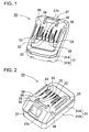
- Fig. 1 is a perspective view showing a battery pack 30.
- Fig. 2 is a perspective view showing the battery pack 30 shown in Fig. 1 as viewed from the rear side.
- Fig. 3 is a front view of the battery pack 30 shown in Fig. 1 .
- Fig. 4 is a plan view of the battery pack 30 shown in Fig. 1 .
- Fig. 5 is a perspective view showing the battery pack 30 shown in Fig. 1 as viewed from the bottom side.
- Fig. 6 is an exploded perspective view of the battery pack 30 shown in Fig. 5 showing a label attachment area 8.
- Fig. 7 is an exploded perspective view showing the battery pack 30 shown in Fig. 1 .
- Fig. 8 is a perspective exploded view showing the battery pack 30 shown in Fig. 7 as viewed from the rear side.
- Fig. 9 shows a cross-sectional perspective view and an enlarged cross-sectional view of the label attachment area 8 along the line IX-IX in Fig. 6 .
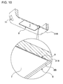
- Fig. 10 shows a cross-sectional perspective view and an enlarged cross-sectional view of the label attachment area along the line X-X in Fig. 5 .
- Fig. 11 is a perspective view showing a closing member 12 shown in Fig. 7 .
- Fig. 12 is a cross-sectional view showing the closing member 12 shown in Fig. 11 with being inserted into a connection hole 11.
- the battery pack 30 according to this example will be illustratively described to be applied to an electric tool as electric equipment to which the battery pack 30 is mounted.
- the illustrated battery pack 30 includes a plurality of rechargeable batteries 39, the battery holder 70, battery lead plates 80, a casing 31, external connection terminals 33, and a lock hook 37b.
- the battery holder 70 holds the plurality of rechargeable batteries 39.
- the battery lead plates 80 connect the end surfaces of the rechargeable batteries 39 to each other.
- the casing 31 accommodates the battery holder 70.
- the external connection terminals 33 are connected to the rechargeable batteries 39, and are exposed externally of the casing 31.
- the lock hook 37b protrudes from the surface of the casing 31, and holds the battery pack with the battery pack being attached to a battery pack charger.
- the casing 31 has a box-shaped outward appearance as shown in Figs. 1 to 4 .
- the corner parts of the casing 31 are rounded.
- the casing 31 has slots 38 in the surface of the casing 31.
- the external connection terminals 33 are exposed from the slots 38.
- the external connection terminals 33 can be connected to the electric tool as electric equipment, or connection terminals 3 of the battery pack charger.
- the casing includes an attachment protruding portion 37 that holds the battery pack 30 with the battery pack 30 being mounted to the electric tool or the battery pack charger after the battery pack 30 is mounted to the electric tool or the battery pack charger.
- the casing 31 is formed of resin or the like having excellent insulation and reinforcement.
- a label 7 is attached onto the back surface of the casing 31.
- the front side of the label 7 shows information including rating of the battery pack, cautions and the like.
- An adhesive such as paste is applied for attachment of the label 7 onto the back side of the label 7.
- the label attachment area 8 is formed on the surface of the casing 31.
- the label 7 is attached onto the label attachment area 8.
- the label attachment area 8 is located on the bottom of a lower case 31 B.
- the label attachment area 8 has a quadrangular (rectangular) shape as viewed in plan view.
- the whole surface of the label attachment area 8 is substantially flat.
- a plurality of grooves 9 are formed in this flat surface.
- the grooves 9 are formed in a recessed slit shape in the flat surface.
- Each of the grooves 9 intersects with at least other one of the grooves 9. It is preferable that the grooves 9 be substantially uniformly distributed in the whole flat surface.
- the grooves 9 extend the longitudinal and transverse directions and are spaced at a constant interval away from each other.
- the entire pattern of the grooves 9 is designed in a grid shape.
- the label can be uniformly adhered on substantially the whole surface of the label attachment area dissimilar to the case of Laid-Open Patent Publication No. JP 2007-69566 A in which the peripheral part of the label is adhered on the label attachment area. Accordingly, in this embodiment, the reliability of adhesion can be improved. In addition, the label can be beautifully attached.
- the flat surface refers to a surface which does not have protruding and recessed parts such as grooves, and does not require a surface which is finely smoothed such as a mirror-finished surface such as in the case of molding die. Even if the flat surface has such a degree of roughness that surface finish is not put on the flat surface, this flat surface can serve the function in the invention as long as having practically sufficient flatness to adhere the label on the flat surface.
- the flat surface in this specification includes a surface which has such a degree of roughness that problems do not arise in practical use.
- the grooves 9 are spaced at a constant interval away from each other, the air bubbles can move to and be discharged through the grooves 9.
- the grooves 9 are formed in a grid shape and intersect with each other so that the grooves 9 extend in the longitudinal and transverse directions, air bubbles can be easily accommodated through the grooves 9.
- bulge and wrinkles of the label 7 caused by air bubbles can be reduced so that the label 7 can be beautifully attached.
- the label attachment work can be easy.
- Air bubbles are not produced not only in attachment of the label but also are likely to be produced in high temperature surroundings. The reason is that air expands under the label 7.
- a peripheral smooth surface part 8B is arranged on a peripheral part of the label attachment area 8.
- the peripheral part of the label 7 is adhered on the periphery smooth surface area 8B. Accordingly, air and air bubbles will be confined. However, the air and air bubbles can flow into the grooves 9, which extend in the longitudinal and transverse directions. As a result, it is possible to suppress bulge and wrinkles of the label 7 caused by air and air bubbles under the label 7.
- a sink mark of the lower case can serve as space for collecting air bubbles.
- the sink mark will be formed in the lower case formed by resin molding when resin is cured.
- a recessed portion of sink mark can be formed in substantially the center of the label attachment area.
- the grooves are formed communicating with the recessed portion.
- air bubbles can move to this recessed portion.
- the air bubbles can be unnoticeable.
- the grooves can be partially arranged outside the label.
- air bubbles can be discharged through this outward extending part from the space between the label attachment area and the label.
- the space is typically closed between the label attachment area and the label, in the case where even a part of the groove is not covered by the label, the closed space communicates with the outside so that air bubbles can be discharged.
- the grooves can extend outward of the label attachment area.
- the label can be formed smaller than the label attachment area. In this construction, even after the label is attached onto the label attachment area, the grooves are not entirely covered by the label. Thus, a part of groove can be arranged outside the label. In other words, the groove can be partially externally exposed.
- the casing 31 includes divided portions of the upper and lower cases 31A and 31 B as shown in the exploded perspective views of Figs. 7 and 8 .
- Accommodation space is formed inside the casing 31.
- the battery holder 70 and the attachment protruding portion 37 are accommodated in this space.
- the aforementioned battery holder 70 is accommodated in the casing 31, as shown in the exploded perspective view of Fig. 7 .
- a sheet member 56 is preferably interposed between the battery holder 70 and the lower case 31 B.
- the sheet member 56 is formed of a material that is excellent in electrical insulation and thermal insulation (e.g., silicon or the like). In the case the sheet member 56 serves as a cushion, it is possible to provide an effect that external shock can be absorbed or reduced. Also, it is possible to reduce the clearance between the battery holder and the bottom of the casing.
- the fastening member 10 can be a screw, fitting structure, or the like. In this embodiment, screw for threaded engagement is used as the fastening member 10.
- the battery pack preferably has an internal structure which cannot be easily disassembled. Alternatively, the battery pack can be constructed for disassembly recognition. In this case, the possibility of modifications can be grasped.
- the closing member 12 closes the connection hole 11 which receives the fastening member 10. Accordingly, the fastening member 10 can be invisible, which in turn can dissuade users from disassembling the battery pack.
- the closing member 12 is press-fitted into the connection hole 11. The closing member 12 is constructed to be damaged if users try to forcedly remove the closing member 12 from the connection hole 11 after the closing member 12 is press-fitted into the connection hole 11. According to this construction, disassembly can be grasped.
- the inventors have diligently studied the construction of the closing member which makes removal of the closing member difficult.
- the inventers have ascertained the operation when the closing member is removed after the closing member is press-fitted into the connection hole. That is, users will incline the closing member inside the connection hole, and create a clearance between the closing member and the connection hole. After that, users will insert a flat member such as flatblade screwdriver into the clearance, and pull the closing member out of the connection hole using leverage.
- the inventers have found that, if the closing member to be press-fitted is not easily inclined inside the connection hole, such operation can be prevented. Therefore, the inventors have developed the closing member having such a structure.
- the closing member 12 is now described with reference to Figs. 11 and 12 .
- the fastening member 10 threadedly engages with the connection hole 11.
- the closing member 12 is inserted into the connection hole 11.
- the closing member 12 serves as a cap which covers the screw head of the screw, which threadedly engages with the connection hole 11.
- the closing member 12 includes a substantially cylindrical member 16, and a plurality of first press-fit portions 13, and a second press-fit portion 14.
- the plurality of first press-fit portions 13 protrude from the side surface of the cylindrical member 16.
- the second press-fit portion 14 forms the end surface of the cylindrical member 16.
- connection hole 11 is formed in a cylindrical shape.
- the closing member 12 is press-fitted into the connection hole 11.
- the closing member 12 is also formed in a substantially cylindrical shape.
- the connection hole 11 is tapered so that the cross-sectional area of the connection hole 11 gets smaller toward the bottom side.
- the second press-fit portion 14 has a disc shape, and serves as a lid which is exposed from the connection hole 11 after the closing member 12 is press-fitted into the connection hole 11.
- the outer diameter of the disc-shaped second press-fit portion 14 is dimensioned substantially equal to the interior diameter of the connection hole 11 at the press-fit position where the closing member 12 is brought in press-fitted contact with the connection hole 11.
- the second press-fit portion 14 is arranged along the circumferential direction and is formed in a flange shape protruding from the circumference of the upper part of the cylindrical member.
- the first press-fit portions 13 extend in the direction in parallel to the center axis of the cylindrical member 16. Accordingly, the second press-fit portion 14 intersects with the first press-fit portions 13.
- the protrusion height of the first press-fit portions 13 is dimensioned lower than the second press-fit portion 14.
- the cylindrical member 11 can be tapered down toward the insertion end to be inserted into the connection hole 11.
- the closing member 12 is integrally formed of a flexible material such as resin by molding.
- Each of the first press-fit portions 13 is formed in a linear ridge shape.
- the first press-fit portions 13 are spaced at a substantially constant interval away from each other along the side surface of the cylindrical member, and protrude from the side surface of the cylindrical member.
- the first press-fit portions 13 come in contact with the inner surface of the connection hole 11. Accordingly, when the closing member 12 is press-fitted into the connection hole 11, the upper part of the closing member 12 contacts the connection hole 11 with the contact part being formed in a circular shape which extends along the circumference of the second press-fit portion 14, while the lower part of the closing member 12 contacts the connection hole 11 at a plurality of locations corresponding to the first press-fit portions 13, which protrude in the lower part of the closing member 12, as shown in Fig.
- the closing member 12 is securely held by the upper and lower parts of the closing member 12, which are arranged along the circumferential direction. Accordingly, the closing member 12 is firmly fixed in the connection hole 11. As a result, it is hard to incline the closing member 12 inside the connection hole 11. As a result, it is difficult for users to incline the closing member 12 inside the connection hole 11 and to remove the closing member 12 from the connection hole 11. Even if users try to forcedly remove the closing member 12, the closing member 12 will be damaged. Thus, a damaged part will be formed on the closing member 12. For this reason, the damaged part will inform that a user disassembles the casing. Therefore, it is possible to easily find modifications of the battery pack.
- a reinforcement portion 15 is formed on the side surface of the cylindrical member 16.
- the reinforcement portion 15 is arranged along the circumferential direction of the cylindrical member 16 so that the second press-fit portion 14 side of the closing member is thicker.
- This reinforcement portion 15 allows each of the first press-fit portions 13 to more surely protrude from the circumference of the cylindrical member 16 and to be more firmly fixed in the connection hole.
- the lower part of the cylindrical member 16 is formed hollow so that the lower end of the cylindrical member 16 is opened. As a result, it is possible to prevent that a sink mark is formed on the closing member 12 formed of resin.
- the hollow part facilitates plastic deformation of the first press-fit portions 13. Therefore, it is possible to the friction of the closing member 12 when the closing member 12 is press-fitted into the connection hole.
- the contact part can be formed in a continuous circular line between the outer surface of the closing member 12 and the inner surface of the connection hole 11.
- the opening of the connection hole 11 can be closed by the second press-fit portion without gap on the continuous circular line.
- the closing effect can be improved. Therefore, it can be difficult for users to forcedly open the connection hole 11.
- the first press-fit portions 13 extend in the direction which intersects with the second press-fit portion (i.e., in the depth direction of the connection hole 11), the friction can be reduced when the closing member 12 is inserted into the connection hole 11.
- the cylindrical member 16 is formed hollow, the closing member 12 can be smoothly inserted into the connection hole 11. Therefore, the press-fit work can be easy.
- first press-fit portions 13 can be coplanar with the side surface of the second press-fit portion 14, while the first press-fit portions 13 can be continuously tapered down toward the lower end.
- the contact area between the closing member 12 and the connection hole inner surface can be increased by line contact of the first press-fit portions with the connection hole inner surface relative to point contact.
- the closing member can more tightly contact the connection hole inner surface. Therefore, it is possible to more surely prevent that foreign matter enters the connection hole and that users forcedly remove the closing member.
- the hook opening window 24 is opened in the upper case 31A.
- the lock hook 37b is exposed from the hook opening window 24.
- the lock hook 37b composes a lock structure, which holds the battery pack 30 for preventing from detachment of the battery pack 30 after the battery pack 30 is mounted to the battery pack charger.
- the lock hook 37b can compose a lock structure, which holds the battery pack 30 for preventing from detachment of the battery pack 30 after the battery pack 30 is mounted to the electric equipment.
- An electric device can be suitably used as electric tool battery pack, and battery packs for mobile devices such as power-assisted bicycle, electric motorcycle, mobile phone, charger, and other devices having a casing onto which a label is attached.
Landscapes
- Chemical & Material Sciences (AREA)
- Chemical Kinetics & Catalysis (AREA)
- Electrochemistry (AREA)
- General Chemical & Material Sciences (AREA)
- Battery Mounting, Suspending (AREA)
- Charge And Discharge Circuits For Batteries Or The Like (AREA)
Abstract
An electric device includes a casing 31, and a label 7. The casing 31 accommodates electronic components. The label 7 is attached on the surface of the casing. A label attachment area 8 is arranged on the surface of the casing. The label 7 is attached onto the label attachment area 8. The label attachment area 8 is formed in a substantially flat surface, and has a plurality of grooves 9. The grooves 9 are uniformly distributed throughout the flat surface. The grooves intersect with each other at least at one point of each of the grooves. The adhesive strength can be kept by the flat surface arranged over substantially the whole of the label attachment area. Air can flow through the grooves uniformly distributed in the flat surface. Bulge or wrinkles of the label can be reduced which are produced by air bubbles.
Description
- The present invention relates to an electric device that is detachably attached to electric equipment such as electric tool and supplies electric power to the electric equipment.
- Electric equipment such as electric tool includes a battery pack which includes a rechargeable battery and is detachably attached to the main unit of the electric equipment. Such electric equipment is useful as a cordless-type tool in construction sites and the like. Since the battery pack can be detached from the main unit of the electric equipment, the detached battery pack can be attached to a battery charger so that the battery pack is charged. Thus, the battery pack can be repeatedly used.
- This type of battery pack has a
label 7 that is attached on the battery pack, and indicates information such as the rating and instructions of the battery pack. The label is constructed of a sticker the back surface of which paste is applied on. The label is attached by the paste on the label attachment area, which is arranged on the surface of a casing of the battery pack. In order to beautifully place the label on the label attachment area, the label attachment area is formed in a flat surface. When the label is attached the label attachment area, if air bubbles are trapped between the label and the label attachment area, problems will arise that the air bubbles obstruct reading of the words written on the label, impairs the appearance, and may cause breaks of the label. For this reason, in attachment of the label, careful attention is required to prevent air bubbles being trapped. If air bubbles are trapped, it is required to detach and attach the label from and onto the label attachment area. Thus, the attachment of the label requires man-hours. On the other hand, even if air bubbles are not trapped or even if trapped air bubbles are so small not to be noticeable, when the battery pack is stored in hot and humid surroundings, a problem may arise that the label is bulged by gas, which appears from resin of the casing. In particular, in the case where the battery cases are stored in hot and humid surroundings during transportation, this problem often arises. - In order to prevent that air bubbles affect the label, it is conceivable that the surface of the label attachment area is grained or is subjected to satin treatment. However, in this case, since a number of protruding and recessed parts are formed on the surface of the label attachment area. Accordingly, the contact surface area is reduced between the label and the label attachment area. As a result, the adhesive strength of the label will be reduced.
- In order to solve such a problem, a resin-formed component has been proposed in Laid-Open Patent Publication No.
JP 2007-69566 A Fig. 13 , the resin-formed component includes a peripheralsmooth surface portion 91 and a centraluneven surface portion 92 in alabel attachment area 90. The peripheralsmooth surface portion 91 is a smooth surface arranged on the peripheral part of thelabel attachment area 90. The centraluneven surface portion 92 has very small protruding and recessed parts and is arranged in the central part of thelabel attachment area 90 surrounded by the peripheralsmooth surface portion 91. High adhesive strength is provided between the peripheralsmooth surface portion 91 and alabel 97. The protruding and recessed parts of the centraluneven surface portion 92 may reduce the adhesive strength of thelabel 91 but can serve to accommodate the gas, which appears from resin. However, even in this construction, since the adhesion surface is limited to the peripheral part of thelabel 97, the central part of thelabel 97 will easily bulge. As a result, there is a problem that air bubbles are likely to gather in the central part of thelabel 97. - Alternatively, it is conceivable that paste is applied in a grid shape on the back surface of a label so that the label can be out of contact with a label attachment area whereby removing air bubbles.
- However, in this case, the grid shape of the paste will be noticeable on the front side of the label. As a result, there is a problem that the appearance of the label is impaired.
- The present invention is devised to solve the above problems. It is a main object to provide an electric device that can significantly reduce air bubbles trapped between a label and the electric device in attachment of the label.
- To achieve the above object, an electric device according to a first aspect of the present invention includes a
casing 31, and alabel 7. Thecasing 31 accommodates electronic components. Thelabel 7 is attached on the surface of the casing. Alabel attachment area 8 is arranged on the surface of the casing. Thelabel 7 is attached onto thelabel attachment area 8. Thelabel attachment area 8 is formed in a substantially flat surface, and has a plurality ofgrooves 9. Thegrooves 9 are uniformly distributed throughout the flat surface. Each of the grooves intersects with at least other one of the grooves. According to this construction, a sufficient adhesive strength can be kept by the flat surface, which is arranged over substantially the whole of the label attachment area. In addition, air can flow through the grooves, which are uniformly distributed in the flat surface. Therefore, it is possible to reduce bulge or wrinkles of the label produced by air bubbles. - In an electric device according to a second aspect of the present invention, the plurality of
grooves 9 can be formed in a grid shape in the flat surface. According to this construction, the grooves can be easily uniformly distributed in the flat surface. Therefore, a sufficient adhesive strength can be kept throughout the flat surface, while it is possible to prevent that air bubbles are trapped between the casing and label. - In an electric device according to a third aspect of the present invention, the plurality of the
grooves 9 can be at least partially exposed outside thelabel 7 after thelabel 7 is attached onto thelabel attachment area 8. According to this construction, the grooves are not entirely covered by the label, but the grooves partially extend outward of the label so that the label does not overlap parts of the grooves. As a result, air bubbles can be discharged through the exposed parts. Therefore, it is possible to effectively prevent that wrinkles and the like are produced. - In an electric device according to a fourth aspect of the present invention, the casing can include upper and lower cases. The casing is constructed by connecting the upper and lower cases to each other by a fastening
member 10. Aconnection hole 11 can be opened in the casing. The fasteningmember 10 is inserted into theconnection hole 11, and connects the upper and lower cases to each other. Theconnection hole 11 can receive aclosing member 12 that closes theconnection hole 11. Theclosing member 12 includes a substantiallycylindrical member 16, a plurality of first press-fit portions 13, and a second press-fit portion 14. The plurality of first press-fit portions 13 protrude from the side surface of thecylindrical member 16, and extend in the direction in parallel to the center axis of thecylindrical member 16. The second press-fit portion 14 protrudes from the side surface of thecylindrical member 16, and is arranged along the circumferential direction of thecylindrical member 16. The second press-fit portion 14 intersects with the first press-fit portions 13. The first press-fit portions 13 and the second press-fit portion 14 are designed to come in contact with the inner surface of theconnection hole 11 when theclosing member 12 is inserted into theconnection hole 11. According to this construction, the elongated first press-fit portions and the circular second press-fit portion come in press-contact with the inner surface of the connection hole. As a result, it is possible to prevent that the closing member is inclined in the connection hole. Once the closing member is inserted into the connection hole, users cannot easily remove the closing member. Therefore, this construction can dissuade users from modifying the electric device. - In an electric device according to a fifth aspect of the present invention, the first press-
fit portions 13 can be continuously formed extending from the side surface of the second press-fit portion 14. According to this construction, the first press-fit portions and the second press-fit portion can have the same height at least in a part of the closing member. Accordingly, the closing member can press the inner surface of the connection hole in the direction intersecting with the inner surface of the connection hole. As a result, the friction can be increased between the closing member and the inner surface of the connection hole. Therefore, it is possible to suppress deviation or inclination of the closing member in the inner surface of the connection hole. - In an electric device according to a sixth aspect of the present invention, the
cylindrical member 16 can be tapered down toward the insertion end to be inserted into theconnection hole 11. - In an electric device according to a seventh aspect of the present invention, the central part of the
cylindrical member 16 can be hollow which is located inside the first press-fit portions 13. According to this construction, it is possible to suppress the sink mark in the case where the closing member is formed by molding. In addition, the closing member can be easily press-fitted into the connection hole. - In an electric device according to an eighth aspect of the present invention, the electric device can be a battery pack.
- In an electric device according to a ninth aspect of the present invention, the electric device can be a charger.
The above and further objects of the present invention as well as the features thereof will become more apparent from the following detailed description to be made in conjunction with the accompanying drawings. -
-
Fig. 1 is a perspective view showing a battery pack; -
Fig. 2 is a perspective view showing the battery pack shown inFig. 1 as viewed from the rear side; -
Fig. 3 is a front view of the battery pack shown inFig. 1 ; -
Fig. 4 is a plan view of the battery pack shown inFig. 1 ; -
Fig. 5 is a perspective view showing the battery pack shown inFig. 1 as viewed from the bottom side; -
Fig. 6 is an exploded perspective view of the battery pack shown inFig. 5 showing a label attachment area; -
Fig. 7 is an exploded perspective view showing the battery pack shown inFig. 1 ; -
Fig. 8 is a perspective exploded view showing the battery pack shown inFig. 7 as viewed from the rear side; -
Fig. 9 shows a cross-sectional perspective view and an enlarged cross-sectional view of the label attachment area along the line IX-IX inFig. 6 ; -
Fig. 10 shows a cross-sectional perspective view and an enlarged cross-sectional view of the label attachment area along the line X-X inFig. 5 ; -
Fig. 11 is a perspective view showing a closing member shown inFig. 7 ; -
Fig. 12 is a cross-sectional view showing the closing member shown inFig. 11 with being inserted into a connection hole; and -
Fig. 13 is a schematic view showing a conventional label attachment structure. - The following description will describe embodiments according to the present invention with reference to the drawings. It should be appreciated, however, that the embodiments described below are illustrations of an electric device used therein to give a concrete form to technical ideas of the invention, and an electric device of the invention is not specifically limited to description below. Furthermore, it should be appreciated that the members shown in claims attached hereto are not specifically limited to members in the embodiments. Unless otherwise specified, any dimensions, materials, shapes and relative arrangements of the members described in the embodiments are given as an example and not as a limitation. Additionally, the sizes and the positional relationships of the members in each of drawings are occasionally shown larger exaggeratingly for ease of explanation. Members same as or similar to those of this invention are attached with the same designation and the same reference numerals, and their description is omitted. In addition, a plurality of structural elements of the present invention may be configured as a single part that serves the purpose of a plurality of elements, on the other hand, a single structural element may be configured as a plurality of parts that serve the purpose of a single element. Also, the description of some of examples or embodiments may be applied to other examples, embodiments or the like.
-
Figs. 1 to 23 show a battery pack as an electric device according to an embodiment of the present invention.Fig. 1 is a perspective view showing abattery pack 30.Fig. 2 is a perspective view showing thebattery pack 30 shown inFig. 1 as viewed from the rear side.Fig. 3 is a front view of thebattery pack 30 shown inFig. 1 .Fig. 4 is a plan view of thebattery pack 30 shown inFig. 1 .Fig. 5 is a perspective view showing thebattery pack 30 shown inFig. 1 as viewed from the bottom side.Fig. 6 is an exploded perspective view of thebattery pack 30 shown inFig. 5 showing alabel attachment area 8.Fig. 7 is an exploded perspective view showing thebattery pack 30 shown inFig. 1 .Fig. 8 is a perspective exploded view showing thebattery pack 30 shown inFig. 7 as viewed from the rear side.Fig. 9 shows a cross-sectional perspective view and an enlarged cross-sectional view of thelabel attachment area 8 along the line IX-IX inFig. 6 .Fig. 10 shows a cross-sectional perspective view and an enlarged cross-sectional view of the label attachment area along the line X-X inFig. 5 .Fig. 11 is a perspective view showing a closingmember 12 shown inFig. 7 .Fig. 12 is a cross-sectional view showing the closingmember 12 shown inFig. 11 with being inserted into aconnection hole 11. Thebattery pack 30 according to this example will be illustratively described to be applied to an electric tool as electric equipment to which thebattery pack 30 is mounted. - The illustrated
battery pack 30 includes a plurality ofrechargeable batteries 39, thebattery holder 70,battery lead plates 80, acasing 31,external connection terminals 33, and alock hook 37b. Thebattery holder 70 holds the plurality ofrechargeable batteries 39. Thebattery lead plates 80 connect the end surfaces of therechargeable batteries 39 to each other. Thecasing 31 accommodates thebattery holder 70. Theexternal connection terminals 33 are connected to therechargeable batteries 39, and are exposed externally of thecasing 31. Thelock hook 37b protrudes from the surface of thecasing 31, and holds the battery pack with the battery pack being attached to a battery pack charger. - The
casing 31 has a box-shaped outward appearance as shown inFigs. 1 to 4 . The corner parts of thecasing 31 are rounded. Also, thecasing 31 hasslots 38 in the surface of thecasing 31. Theexternal connection terminals 33 are exposed from theslots 38. Theexternal connection terminals 33 can be connected to the electric tool as electric equipment, or connection terminals 3 of the battery pack charger. Also, the casing includes anattachment protruding portion 37 that holds thebattery pack 30 with thebattery pack 30 being mounted to the electric tool or the battery pack charger after thebattery pack 30 is mounted to the electric tool or the battery pack charger. Thecasing 31 is formed of resin or the like having excellent insulation and reinforcement. - As shown in
Figs. 5 to 8 , alabel 7 is attached onto the back surface of thecasing 31. The front side of thelabel 7 shows information including rating of the battery pack, cautions and the like. An adhesive such as paste is applied for attachment of thelabel 7 onto the back side of thelabel 7. On the other hand, thelabel attachment area 8 is formed on the surface of thecasing 31. Thelabel 7 is attached onto thelabel attachment area 8. In the case ofFig. 6 , thelabel attachment area 8 is located on the bottom of alower case 31 B. - The
label attachment area 8 has a quadrangular (rectangular) shape as viewed in plan view. The whole surface of thelabel attachment area 8 is substantially flat. A plurality ofgrooves 9 are formed in this flat surface. Thegrooves 9 are formed in a recessed slit shape in the flat surface. Each of thegrooves 9 intersects with at least other one of thegrooves 9. It is preferable that thegrooves 9 be substantially uniformly distributed in the whole flat surface. In the case ofFig. 6 , thegrooves 9 extend the longitudinal and transverse directions and are spaced at a constant interval away from each other. Thus, the entire pattern of thegrooves 9 is designed in a grid shape. In the case where a number ofgrooves 9 are formed in a narrow slot shape in thelabel attachment area 8, even if air bubbles and the like are trapped between thelabel 7 and thelabel attachment area 8 in attachment of thelabel 7, air can flow into and be accommodated in thegrooves 9. As a result, it is possible to reduce bulge or wrinkles of thelabel 7. Also, as shown in the cross-sectional view ofFig. 9 , since thegrooves 9 are formed in a narrow slot shape, most parts of thelabel attachment area 8 can be a flat surface. Accordingly, thelabel 7 can have a large contact area withlabel attachment area 8. As a result, a sufficient adhesive strength can be kept. In this embodiment, the label can be uniformly adhered on substantially the whole surface of the label attachment area dissimilar to the case of Laid-Open Patent Publication No.JP 2007-69566 A - In this specification, the flat surface refers to a surface which does not have protruding and recessed parts such as grooves, and does not require a surface which is finely smoothed such as a mirror-finished surface such as in the case of molding die. Even if the flat surface has such a degree of roughness that surface finish is not put on the flat surface, this flat surface can serve the function in the invention as long as having practically sufficient flatness to adhere the label on the flat surface. Thus, the flat surface in this specification includes a surface which has such a degree of roughness that problems do not arise in practical use.
- On the other hand, even if air bubbles are trapped between the
label 7 and thelabel attachment area 8 in the attachment of the label as discussed above, since thegrooves 9 are spaced at a constant interval away from each other, the air bubbles can move to and be discharged through thegrooves 9. In particular, in the case where thegrooves 9 are formed in a grid shape and intersect with each other so that thegrooves 9 extend in the longitudinal and transverse directions, air bubbles can be easily accommodated through thegrooves 9. As a result, there is an advantage that bulge and wrinkles of thelabel 7 caused by air bubbles can be reduced so that thelabel 7 can be beautifully attached. In addition, there is an advantage that the label attachment work can be easy. Air bubbles are not produced not only in attachment of the label but also are likely to be produced in high temperature surroundings. The reason is that air expands under thelabel 7. In this embodiment, as shown inFigs. 6 ,9 and10 , a peripheralsmooth surface part 8B is arranged on a peripheral part of thelabel attachment area 8. In this case, the peripheral part of thelabel 7 is adhered on the peripherysmooth surface area 8B. Accordingly, air and air bubbles will be confined. However, the air and air bubbles can flow into thegrooves 9, which extend in the longitudinal and transverse directions. As a result, it is possible to suppress bulge and wrinkles of thelabel 7 caused by air and air bubbles under thelabel 7. - Also, a sink mark of the lower case can serve as space for collecting air bubbles. The sink mark will be formed in the lower case formed by resin molding when resin is cured. For example, a recessed portion of sink mark can be formed in substantially the center of the label attachment area. In this case, the grooves are formed communicating with the recessed portion. Thus, air bubbles can move to this recessed portion. As a result, the air bubbles can be unnoticeable.
- Alternatively, the grooves can be partially arranged outside the label. In this case, air bubbles can be discharged through this outward extending part from the space between the label attachment area and the label. In other words, although the space is typically closed between the label attachment area and the label, in the case where even a part of the groove is not covered by the label, the closed space communicates with the outside so that air bubbles can be discharged. For example, the grooves can extend outward of the label attachment area. Alternatively, the label can be formed smaller than the label attachment area. In this construction, even after the label is attached onto the label attachment area, the grooves are not entirely covered by the label. Thus, a part of groove can be arranged outside the label. In other words, the groove can be partially externally exposed. As a result, since the grooves intersect with each other so that all of the grooves communicate with each other, all of the grooves can communicate with the outside of the label through the exposed part of the groove. Therefore, air bubbles can be discharged outward through this exposed part of the groove. According to this construction, since the label can be attached without much concern for trapping of air bubbles, the label attachment work can be easier.
- The
casing 31 includes divided portions of the upper andlower cases Figs. 7 and8 . Accommodation space is formed inside thecasing 31. Thebattery holder 70 and theattachment protruding portion 37 are accommodated in this space. - The
aforementioned battery holder 70 is accommodated in thecasing 31, as shown in the exploded perspective view ofFig. 7 . Asheet member 56 is preferably interposed between thebattery holder 70 and thelower case 31 B. Thesheet member 56 is formed of a material that is excellent in electrical insulation and thermal insulation (e.g., silicon or the like). In the case thesheet member 56 serves as a cushion, it is possible to provide an effect that external shock can be absorbed or reduced. Also, it is possible to reduce the clearance between the battery holder and the bottom of the casing. - The upper and lower cases are coupled by the
fastening member 10. Thefastening member 10 can be a screw, fitting structure, or the like. In this embodiment, screw for threaded engagement is used as thefastening member 10. In order to prevent that undesirable modifications cause accidents and the like, the battery pack preferably has an internal structure which cannot be easily disassembled. Alternatively, the battery pack can be constructed for disassembly recognition. In this case, the possibility of modifications can be grasped. To achieve this, the closingmember 12 closes theconnection hole 11 which receives thefastening member 10. Accordingly, thefastening member 10 can be invisible, which in turn can dissuade users from disassembling the battery pack. In addition, the closingmember 12 is press-fitted into theconnection hole 11. The closingmember 12 is constructed to be damaged if users try to forcedly remove the closingmember 12 from theconnection hole 11 after the closingmember 12 is press-fitted into theconnection hole 11. According to this construction, disassembly can be grasped. - From this viewpoint, the inventors have diligently studied the construction of the closing member which makes removal of the closing member difficult. As a result, the inventers have ascertained the operation when the closing member is removed after the closing member is press-fitted into the connection hole. That is, users will incline the closing member inside the connection hole, and create a clearance between the closing member and the connection hole. After that, users will insert a flat member such as flatblade screwdriver into the clearance, and pull the closing member out of the connection hole using leverage. For this reason, the inventers have found that, if the closing member to be press-fitted is not easily inclined inside the connection hole, such operation can be prevented. Therefore, the inventors have developed the closing member having such a structure.
- The closing
member 12 is now described with reference toFigs. 11 and 12 . In this embodiment, thefastening member 10 threadedly engages with theconnection hole 11. Again, the closingmember 12 is inserted into theconnection hole 11. The closingmember 12 serves as a cap which covers the screw head of the screw, which threadedly engages with theconnection hole 11. The closingmember 12 includes a substantiallycylindrical member 16, and a plurality of first press-fit portions 13, and a second press-fit portion 14. The plurality of first press-fit portions 13 protrude from the side surface of thecylindrical member 16. The second press-fit portion 14 forms the end surface of thecylindrical member 16. - The
connection hole 11 is formed in a cylindrical shape. Again, the closingmember 12 is press-fitted into theconnection hole 11. Correspondingly, the closingmember 12 is also formed in a substantially cylindrical shape. In order that the closingmember 12 may not be detached from theconnection hole 11 after being press-fitted into theconnection hole 11, theconnection hole 11 is tapered so that the cross-sectional area of theconnection hole 11 gets smaller toward the bottom side. The second press-fit portion 14 has a disc shape, and serves as a lid which is exposed from theconnection hole 11 after the closingmember 12 is press-fitted into theconnection hole 11. The outer diameter of the disc-shaped second press-fit portion 14 is dimensioned substantially equal to the interior diameter of theconnection hole 11 at the press-fit position where the closingmember 12 is brought in press-fitted contact with theconnection hole 11. - The second press-
fit portion 14 is arranged along the circumferential direction and is formed in a flange shape protruding from the circumference of the upper part of the cylindrical member. On the other hand, the first press-fit portions 13 extend in the direction in parallel to the center axis of thecylindrical member 16. Accordingly, the second press-fit portion 14 intersects with the first press-fit portions 13. In order that the closing member may be inserted into theconnection hole 11 with tapered inner surface, as shown inFig. 12 , the protrusion height of the first press-fit portions 13 is dimensioned lower than the second press-fit portion 14. Also, thecylindrical member 11 can be tapered down toward the insertion end to be inserted into theconnection hole 11. The closingmember 12 is integrally formed of a flexible material such as resin by molding. - Each of the first press-
fit portions 13 is formed in a linear ridge shape. The first press-fit portions 13 are spaced at a substantially constant interval away from each other along the side surface of the cylindrical member, and protrude from the side surface of the cylindrical member. In addition, the first press-fit portions 13 come in contact with the inner surface of theconnection hole 11. Accordingly, when the closingmember 12 is press-fitted into theconnection hole 11, the upper part of the closingmember 12 contacts theconnection hole 11 with the contact part being formed in a circular shape which extends along the circumference of the second press-fit portion 14, while the lower part of the closingmember 12 contacts theconnection hole 11 at a plurality of locations corresponding to the first press-fit portions 13, which protrude in the lower part of the closingmember 12, as shown inFig. 12 . Thus, the closingmember 12 is securely held by the upper and lower parts of the closingmember 12, which are arranged along the circumferential direction. Accordingly, the closingmember 12 is firmly fixed in theconnection hole 11. As a result, it is hard to incline the closingmember 12 inside theconnection hole 11. As a result, it is difficult for users to incline the closingmember 12 inside theconnection hole 11 and to remove the closingmember 12 from theconnection hole 11. Even if users try to forcedly remove the closingmember 12, the closingmember 12 will be damaged. Thus, a damaged part will be formed on the closingmember 12. For this reason, the damaged part will inform that a user disassembles the casing. Therefore, it is possible to easily find modifications of the battery pack. - Also, in order that the first press-
fit portions 13 can surely protrude from thecylindrical member 16, in the case ofFig. 11 , areinforcement portion 15 is formed on the side surface of thecylindrical member 16. Thereinforcement portion 15 is arranged along the circumferential direction of thecylindrical member 16 so that the second press-fit portion 14 side of the closing member is thicker. Thisreinforcement portion 15 allows each of the first press-fit portions 13 to more surely protrude from the circumference of thecylindrical member 16 and to be more firmly fixed in the connection hole. On the other hand, the lower part of thecylindrical member 16 is formed hollow so that the lower end of thecylindrical member 16 is opened. As a result, it is possible to prevent that a sink mark is formed on the closingmember 12 formed of resin. In addition, the hollow part facilitates plastic deformation of the first press-fit portions 13. Therefore, it is possible to the friction of the closingmember 12 when the closingmember 12 is press-fitted into the connection hole. - In particular, as discussed above, since the second press-
fit portion 14 is formed in a protruding circular shape, the contact part can be formed in a continuous circular line between the outer surface of the closingmember 12 and the inner surface of theconnection hole 11. Thus, the opening of theconnection hole 11 can be closed by the second press-fit portion without gap on the continuous circular line. As a result, the closing effect can be improved. Therefore, it can be difficult for users to forcedly open theconnection hole 11. On the other hand, since the first press-fit portions 13 extend in the direction which intersects with the second press-fit portion (i.e., in the depth direction of the connection hole 11), the friction can be reduced when the closingmember 12 is inserted into theconnection hole 11. Also, in addition to this, since thecylindrical member 16 is formed hollow, the closingmember 12 can be smoothly inserted into theconnection hole 11. Therefore, the press-fit work can be easy. - In addition, the upper ends of the first press-
fit portions 13 can be coplanar with the side surface of the second press-fit portion 14, while the first press-fit portions 13 can be continuously tapered down toward the lower end. In this case, the contact area between the closingmember 12 and the connection hole inner surface can be increased by line contact of the first press-fit portions with the connection hole inner surface relative to point contact. As a result, the closing member can more tightly contact the connection hole inner surface. Therefore, it is possible to more surely prevent that foreign matter enters the connection hole and that users forcedly remove the closing member. - As shown in
Fig. 4 or the like, thehook opening window 24 is opened in theupper case 31A. Thelock hook 37b is exposed from thehook opening window 24. Thelock hook 37b composes a lock structure, which holds thebattery pack 30 for preventing from detachment of thebattery pack 30 after thebattery pack 30 is mounted to the battery pack charger. Also, thelock hook 37b can compose a lock structure, which holds thebattery pack 30 for preventing from detachment of thebattery pack 30 after thebattery pack 30 is mounted to the electric equipment. - An electric device according to the present invention can be suitably used as electric tool battery pack, and battery packs for mobile devices such as power-assisted bicycle, electric motorcycle, mobile phone, charger, and other devices having a casing onto which a label is attached.
It should be apparent to those with an ordinary skill in the art that while various preferred embodiments of the invention have been shown and described, it is contemplated that the invention is not limited to the particular embodiments disclosed, which are deemed to be merely illustrative of the inventive concepts and should not be interpreted as limiting the scope of the invention, and which are suitable for all modifications and changes falling within the scope of the invention as defined in the appended claims.
Claims (9)
- An electric device comprising:a casing (31) that accommodates electronic components; anda label (7) that is attached onto the surface of said casing,wherein a label attachment area (8) is arranged on the surface of said casing, said label (7) being attached onto the label attachment area (8),characterized in that:said label attachment area (8) is formed in a substantially flat surface, and has a plurality of grooves (9) that are uniformly distributed throughout the flat surface, wherein each of the grooves (9) intersects with at least other one of the grooves (9).
- The electric device according to claim 1, wherein said plurality of grooves (9) are formed in a grid shape in said flat surface.
- The electric device according to claim 1 or 2, wherein said plurality of said grooves (9) are at least partially exposed outside said label (7) after said label (7) is attached onto the label attachment area (8).
- The electric device according to any of claims 1 to 3,
wherein said casing includes divided parts of upper and lower cases, wherein said casing is constructed by connecting said upper and lower cases to each other by a fastening member (10),
wherein a connection hole (11) is opened in said casing, the fastening member (10) being inserted into the connection hole (11) and connecting said upper and lower cases to each other,
wherein said connection hole (11) can receive a closing member (12) that closes said connection hole (11),
wherein said closing member (12) includes
a substantially cylindrical member (16),
a plurality of first press-fit portions (13) that protrude from the side surface of said cylindrical member (16), and extend in the direction in parallel to the center axis of the cylindrical member (16), and
a second press-fit portion (14) that protrudes from the side surface of said cylindrical member (16), and is arranged along the circumferential direction of the cylindrical member (16), the second press-fit portion (14) intersecting with said first press-fit portions (13),
wherein said first press-fit portions (13) and said second press-fit portion (14) are designed to come in contact with the inner surface of the connection hole (11) when said closing member (12) is inserted into said connection hole (11). - The electric device according to claim 4, wherein said first press-fit portions (13) is continuously formed extending from the side surface of said second press-fit portion (14).
- The electric device according to claim 4 or 5, wherein said cylindrical member (16) is tapered down toward the insertion end to be inserted into said connection hole (11).
- The electric device according to any of claims 4 to 6, wherein the central part of said cylindrical member (16) is hollow which is located inside said first press-fit portions (13).
- The electric device according to any of claims 1 to 7, wherein said electric device is a battery pack.
- The electric device according to any of claims 1 to 7, wherein said electric device is a charger.
Applications Claiming Priority (1)
| Application Number | Priority Date | Filing Date | Title |
|---|---|---|---|
| JP2010184810A JP2012043685A (en) | 2010-08-20 | 2010-08-20 | Electrical equipment |
Publications (1)
| Publication Number | Publication Date |
|---|---|
| EP2421068A1 true EP2421068A1 (en) | 2012-02-22 |
Family
ID=44720478
Family Applications (1)
| Application Number | Title | Priority Date | Filing Date |
|---|---|---|---|
| EP11006771A Withdrawn EP2421068A1 (en) | 2010-08-20 | 2011-08-18 | An electric device with a label attached |
Country Status (4)
| Country | Link |
|---|---|
| US (1) | US20120043928A1 (en) |
| EP (1) | EP2421068A1 (en) |
| JP (1) | JP2012043685A (en) |
| CN (1) | CN102412374A (en) |
Cited By (1)
| Publication number | Priority date | Publication date | Assignee | Title |
|---|---|---|---|---|
| CN114400402A (en) * | 2022-03-24 | 2022-04-26 | 深圳市玖木科技发展有限公司 | Storage battery of air purification equipment and power supply output connection assembly thereof |
Families Citing this family (4)
| Publication number | Priority date | Publication date | Assignee | Title |
|---|---|---|---|---|
| JPWO2017168847A1 (en) * | 2016-03-29 | 2019-02-07 | 日立化成株式会社 | Airgel layered member |
| USD818948S1 (en) * | 2017-03-09 | 2018-05-29 | 7Rdd Limited | Battery pack |
| USD819562S1 (en) * | 2017-03-09 | 2018-06-05 | 7Rdd Limited | Battery pack |
| JP7348106B2 (en) * | 2020-03-02 | 2023-09-20 | 株式会社クボタ | Information labels for work vehicles and work vehicles |
Citations (5)
| Publication number | Priority date | Publication date | Assignee | Title |
|---|---|---|---|---|
| US3160970A (en) * | 1962-05-25 | 1964-12-15 | Electric Storage Battery Co | Storage battery container |
| JPH09179496A (en) * | 1995-12-21 | 1997-07-11 | Toyo Seikan Kaisha Ltd | Tack label and labeled container |
| JP2007069566A (en) | 2005-09-09 | 2007-03-22 | Canon Inc | Plastic molded product |
| US20080213652A1 (en) * | 2007-02-08 | 2008-09-04 | Karl Frederick Scheucher | Battery pack safety and thermal management apparatus and method |
| CN201305158Y (en) * | 2008-11-13 | 2009-09-09 | 高效电子股份有限公司 | Shell plate grid structure for sticking label paper |
Family Cites Families (5)
| Publication number | Priority date | Publication date | Assignee | Title |
|---|---|---|---|---|
| JPH07223620A (en) * | 1994-02-08 | 1995-08-22 | Mitsumi Electric Co Ltd | Adhesive surface structure of label |
| JPH10105067A (en) * | 1996-09-27 | 1998-04-24 | Sony Corp | Equipment cabinet |
| JP3806569B2 (en) * | 2000-02-25 | 2006-08-09 | 三洋電機株式会社 | Desktop electrical equipment |
| JP2002374073A (en) * | 2001-06-13 | 2002-12-26 | Toshiba Corp | Electrical equipment cabinet |
| JP5334160B2 (en) * | 2008-08-08 | 2013-11-06 | Necエナジーデバイス株式会社 | Battery pack with nameplate |
-
2010
- 2010-08-20 JP JP2010184810A patent/JP2012043685A/en active Pending
-
2011
- 2011-08-18 US US13/212,468 patent/US20120043928A1/en not_active Abandoned
- 2011-08-18 EP EP11006771A patent/EP2421068A1/en not_active Withdrawn
- 2011-08-19 CN CN2011102405969A patent/CN102412374A/en active Pending
Patent Citations (5)
| Publication number | Priority date | Publication date | Assignee | Title |
|---|---|---|---|---|
| US3160970A (en) * | 1962-05-25 | 1964-12-15 | Electric Storage Battery Co | Storage battery container |
| JPH09179496A (en) * | 1995-12-21 | 1997-07-11 | Toyo Seikan Kaisha Ltd | Tack label and labeled container |
| JP2007069566A (en) | 2005-09-09 | 2007-03-22 | Canon Inc | Plastic molded product |
| US20080213652A1 (en) * | 2007-02-08 | 2008-09-04 | Karl Frederick Scheucher | Battery pack safety and thermal management apparatus and method |
| CN201305158Y (en) * | 2008-11-13 | 2009-09-09 | 高效电子股份有限公司 | Shell plate grid structure for sticking label paper |
Cited By (1)
| Publication number | Priority date | Publication date | Assignee | Title |
|---|---|---|---|---|
| CN114400402A (en) * | 2022-03-24 | 2022-04-26 | 深圳市玖木科技发展有限公司 | Storage battery of air purification equipment and power supply output connection assembly thereof |
Also Published As
| Publication number | Publication date |
|---|---|
| CN102412374A (en) | 2012-04-11 |
| US20120043928A1 (en) | 2012-02-23 |
| JP2012043685A (en) | 2012-03-01 |
Similar Documents
| Publication | Publication Date | Title |
|---|---|---|
| EP2421068A1 (en) | An electric device with a label attached | |
| JP2008305774A (en) | Battery pack | |
| KR101430620B1 (en) | Battery Pack | |
| JP2003257388A (en) | Rechargeable battery storage case | |
| US20080118823A1 (en) | Battery housing structures | |
| CN101901942A (en) | Charger for 2 types of square rechargeable batteries | |
| EP4060801B1 (en) | Battery pack having structure for preventing loosening of handle | |
| CN111133607B (en) | Power supply device | |
| CN101267025B (en) | Support foot for battery pack, battery pack with the same and method of manufacturing the same | |
| JP2014056807A (en) | Battery pack | |
| JP2005100689A (en) | Battery pack | |
| CN111194487A (en) | power supply unit | |
| JP2021150003A (en) | Battery pack | |
| JP5575857B2 (en) | Battery fixing device and electronic device using the same | |
| JP2001093496A (en) | Storage case for flat battery and battery pack using the same | |
| CN111164784B (en) | Power supply device | |
| EP2720286B1 (en) | Secondary battery | |
| JP5299401B2 (en) | Storage battery handle connection structure and lead storage battery with handle | |
| JP6350056B2 (en) | Storage battery handle connection structure and lead storage battery with handle | |
| JP2008140730A (en) | Packed battery | |
| JP3625734B2 (en) | Pack battery | |
| JP4488717B2 (en) | Pack battery | |
| JP6705709B2 (en) | Bicycle components | |
| JP2804735B2 (en) | Manufacturing method of battery pack | |
| JP4761765B2 (en) | Pack battery |
Legal Events
| Date | Code | Title | Description |
|---|---|---|---|
| AK | Designated contracting states |
Kind code of ref document: A1 Designated state(s): AL AT BE BG CH CY CZ DE DK EE ES FI FR GB GR HR HU IE IS IT LI LT LU LV MC MK MT NL NO PL PT RO RS SE SI SK SM TR |
|
| AX | Request for extension of the european patent |
Extension state: BA ME |
|
| PUAI | Public reference made under article 153(3) epc to a published international application that has entered the european phase |
Free format text: ORIGINAL CODE: 0009012 |
|
| 17P | Request for examination filed |
Effective date: 20120810 |
|
| STAA | Information on the status of an ep patent application or granted ep patent |
Free format text: STATUS: THE APPLICATION HAS BEEN WITHDRAWN |
|
| 18W | Application withdrawn |
Effective date: 20131217 |