EP2420878A2 - Fiber optic cable with improved low temperature and compression resistance - Google Patents
Fiber optic cable with improved low temperature and compression resistance Download PDFInfo
- Publication number
- EP2420878A2 EP2420878A2 EP11305912A EP11305912A EP2420878A2 EP 2420878 A2 EP2420878 A2 EP 2420878A2 EP 11305912 A EP11305912 A EP 11305912A EP 11305912 A EP11305912 A EP 11305912A EP 2420878 A2 EP2420878 A2 EP 2420878A2
- Authority
- EP
- European Patent Office
- Prior art keywords
- fiber optic
- jacket
- optic cable
- cable
- strength members
- Prior art date
- Legal status (The legal status is an assumption and is not a legal conclusion. Google has not performed a legal analysis and makes no representation as to the accuracy of the status listed.)
- Withdrawn
Links
- 239000000835 fiber Substances 0.000 title claims abstract description 75
- 230000006835 compression Effects 0.000 title description 4
- 238000007906 compression Methods 0.000 title description 4
- 230000008602 contraction Effects 0.000 claims abstract description 32
- 239000013307 optical fiber Substances 0.000 claims abstract description 10
- 239000000945 filler Substances 0.000 claims description 24
- 239000002033 PVDF binder Substances 0.000 claims description 19
- 229920003023 plastic Polymers 0.000 claims description 15
- 239000004033 plastic Substances 0.000 claims description 15
- 239000004800 polyvinyl chloride Substances 0.000 claims description 13
- 229920000915 polyvinyl chloride Polymers 0.000 claims description 13
- 239000011230 binding agent Substances 0.000 claims description 12
- 229920003235 aromatic polyamide Polymers 0.000 claims description 11
- 229920000642 polymer Polymers 0.000 claims description 11
- 239000000843 powder Substances 0.000 claims description 10
- 239000011521 glass Substances 0.000 claims description 8
- 239000004760 aramid Substances 0.000 claims description 7
- XLYOFNOQVPJJNP-UHFFFAOYSA-N water Substances O XLYOFNOQVPJJNP-UHFFFAOYSA-N 0.000 claims description 7
- PNEYBMLMFCGWSK-UHFFFAOYSA-N aluminium oxide Inorganic materials [O-2].[O-2].[O-2].[Al+3].[Al+3] PNEYBMLMFCGWSK-UHFFFAOYSA-N 0.000 claims description 6
- 150000004684 trihydrates Chemical class 0.000 claims description 6
- 239000003063 flame retardant Substances 0.000 claims description 5
- 239000011800 void material Substances 0.000 claims description 4
- VTHJTEIRLNZDEV-UHFFFAOYSA-L magnesium dihydroxide Chemical compound [OH-].[OH-].[Mg+2] VTHJTEIRLNZDEV-UHFFFAOYSA-L 0.000 claims description 2
- 239000000347 magnesium hydroxide Substances 0.000 claims description 2
- 229910001862 magnesium hydroxide Inorganic materials 0.000 claims description 2
- 239000012764 mineral filler Substances 0.000 claims description 2
- 230000007704 transition Effects 0.000 claims description 2
- 239000000126 substance Substances 0.000 claims 2
- XAGFODPZIPBFFR-UHFFFAOYSA-N aluminium Chemical group [Al] XAGFODPZIPBFFR-UHFFFAOYSA-N 0.000 claims 1
- 229910052782 aluminium Inorganic materials 0.000 claims 1
- 238000013461 design Methods 0.000 description 17
- 229920002981 polyvinylidene fluoride Polymers 0.000 description 16
- 239000000463 material Substances 0.000 description 9
- 230000008901 benefit Effects 0.000 description 5
- 230000003247 decreasing effect Effects 0.000 description 4
- -1 polyethylene Polymers 0.000 description 3
- 239000000779 smoke Substances 0.000 description 3
- RNFJDJUURJAICM-UHFFFAOYSA-N 2,2,4,4,6,6-hexaphenoxy-1,3,5-triaza-2$l^{5},4$l^{5},6$l^{5}-triphosphacyclohexa-1,3,5-triene Chemical compound N=1P(OC=2C=CC=CC=2)(OC=2C=CC=CC=2)=NP(OC=2C=CC=CC=2)(OC=2C=CC=CC=2)=NP=1(OC=1C=CC=CC=1)OC1=CC=CC=C1 RNFJDJUURJAICM-UHFFFAOYSA-N 0.000 description 2
- 239000004698 Polyethylene Substances 0.000 description 2
- 239000003795 chemical substances by application Substances 0.000 description 2
- 238000004891 communication Methods 0.000 description 2
- 230000007613 environmental effect Effects 0.000 description 2
- 238000011049 filling Methods 0.000 description 2
- 230000009970 fire resistant effect Effects 0.000 description 2
- 230000006872 improvement Effects 0.000 description 2
- 238000012986 modification Methods 0.000 description 2
- 230000004048 modification Effects 0.000 description 2
- 239000004014 plasticizer Substances 0.000 description 2
- 229920000573 polyethylene Polymers 0.000 description 2
- 238000012360 testing method Methods 0.000 description 2
- 239000000654 additive Substances 0.000 description 1
- 230000000996 additive effect Effects 0.000 description 1
- RREGISFBPQOLTM-UHFFFAOYSA-N alumane;trihydrate Chemical compound O.O.O.[AlH3] RREGISFBPQOLTM-UHFFFAOYSA-N 0.000 description 1
- 239000002981 blocking agent Substances 0.000 description 1
- 230000015556 catabolic process Effects 0.000 description 1
- 230000008859 change Effects 0.000 description 1
- 239000011248 coating agent Substances 0.000 description 1
- 238000000576 coating method Methods 0.000 description 1
- 238000002485 combustion reaction Methods 0.000 description 1
- 239000002131 composite material Substances 0.000 description 1
- 238000010276 construction Methods 0.000 description 1
- 238000006731 degradation reaction Methods 0.000 description 1
- 238000001035 drying Methods 0.000 description 1
- 125000000816 ethylene group Chemical group [H]C([H])([*:1])C([H])([H])[*:2] 0.000 description 1
- 238000001125 extrusion Methods 0.000 description 1
- 239000000446 fuel Substances 0.000 description 1
- 239000003365 glass fiber Substances 0.000 description 1
- 238000009863 impact test Methods 0.000 description 1
- 238000009434 installation Methods 0.000 description 1
- 239000012212 insulator Substances 0.000 description 1
- 238000005259 measurement Methods 0.000 description 1
- 238000000034 method Methods 0.000 description 1
- 229920000728 polyester Polymers 0.000 description 1
- 230000008569 process Effects 0.000 description 1
- 230000009467 reduction Effects 0.000 description 1
- 230000007480 spreading Effects 0.000 description 1
- 238000006467 substitution reaction Methods 0.000 description 1
Images


Classifications
-
- G—PHYSICS
- G02—OPTICS
- G02B—OPTICAL ELEMENTS, SYSTEMS OR APPARATUS
- G02B6/00—Light guides; Structural details of arrangements comprising light guides and other optical elements, e.g. couplings
- G02B6/44—Mechanical structures for providing tensile strength and external protection for fibres, e.g. optical transmission cables
- G02B6/4401—Optical cables
- G02B6/4429—Means specially adapted for strengthening or protecting the cables
-
- G—PHYSICS
- G02—OPTICS
- G02B—OPTICAL ELEMENTS, SYSTEMS OR APPARATUS
- G02B6/00—Light guides; Structural details of arrangements comprising light guides and other optical elements, e.g. couplings
- G02B6/44—Mechanical structures for providing tensile strength and external protection for fibres, e.g. optical transmission cables
- G02B6/4401—Optical cables
- G02B6/441—Optical cables built up from sub-bundles
- G02B6/4413—Helical structure
Definitions
- This application relates to communication cables. More particularly, this application relates to loose-tube type fiber optic cables.
- Fiber optic cables In the area of fiber optic cables, there are many different designs, each of which has some purpose both in fiber count, mechanical properties, environmental resistance properties, fire resistance/smoke, etc... Among the various designs, mid count-designs (eg. more than 12 - less than 100 fibers) typically contain the fibers in a loose tube style arrangement.
- "Loose tube” is a commonly understood term designating a fiber cable design that has a jacket, at least one buffer tube inside the jacket with at least one (usually more) UV coated optical fiber(s) loosely contained inside each buffer tube. More particularly, the "loose” term in “loose tube” refers to the fibers being loose within buffer tube thus allowing the fibers to reside within a relatively free space.
- the fibers have the ability to bend/move (such as into a sinusoidal shape) along the length of the cable, accumulating as the cable (jacket and tubes) contracts over cold temperature extremes.
- the fibers are able to avoid the stresses imparted by the cold temperatures on the tubes and jacket and thus likewise avoid undue attenuation.
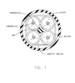
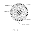
- Figures 1 and 2 show typical prior art loose tube fiber optic cables for forty eight (48) fibers ( figure 1 ) and seventy two (72) fibers ( figure 2 ).
- a jacket is provided with either four or six buffer tubes each having twelve (12) loose fibers therein.
- Each of the tubes are arranged around a central strength member, typically a GRP (Glass Reinforced Polymer) to provide various mechanical advantages to the cable including longitudinal strength, and cold temperature contraction resistance, cable resistance, etc...
- GRP Glass Reinforced Polymer
- aramid strength strands are added to the interior of the tube(s) to aid with the process of adding connectors to the fibers at the ends of tubes (i.e. once they are removed from the cable for connectorization).
- a normal design feature for fiber optic cables is a cold temperature resistance rating, meaning that the cable does not overly attenuate at some particular cold temperature. For example, in many designs for mid-count fiber optic cables, there is a maximum allowable attenuation of 0.3 db change under low temperature conditions (typically either 0 C, -20 C or -40 C).
- the polymers typically used for a jacket and the buffer tubes such a PE (polyethylene), PVC/FRPVC (polyvinylchloride/ flame retardant polyvinylchloride), FEP (Fluorinated Ethylene Polymer), PVDF (Polyvinylidene Fluoride) etc..., shrink a good amount, eg. between 0.2 % to 1.5% shrinkage through the transition from room temp (23oC) to cold temperatures (to -40oC).
- the UV coated glass fibers loosely contained in the buffer tubes, also contracts in the cold, but to a much lesser extent, e.g. approximately 0.08%-1%.
- the Aramid in the outer layer actually undergoes a moderate expansion in cold temperatures.
- the GRP a composite of glass and plastic, only contracts a slight amount, e.g. approximately 0.04%.
- the present arrangement overcomes the drawbacks associated with the prior art and provides a loose tube fiber optic cable design for mid-count fiber optic cables that is capable of significantly improved cold temperature resistance, such as maximum attenuation of 0.07 db increase when decreasing from -23°C to -60°C.
- the present arrangement has additional advantages regarding other mechanical characteristics including improved crush resistance and moisture resistance.
- a fiber optic cable is provided with a plurality of buffer tubes each with one or more optical fibers, a plurality of strength members and a jacket.
- the fibers within the cable meet maximum attenuation of substantially 0.07 db increase when decreasing from -23°C to -60°C.
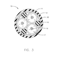
- a fiber optic cable 10 for containing thirty six (36) fibers.
- Cable 10 includes an outer jacket 12 and three (3) buffer tubes 14 therein.
- Buffer tubes 14 are preferably constructed of FRPVC (Flame Resistant Polyvinylchloride), and jacket 12 is made from either PVDF (Polyvinylidene Fluoride) or FRPVC. It is noted that the invention is not limited in this respect and the features described herein for cable 10 may be used in cable construction using other polymers for jacket 12 and tubes 14 as desired.
- PVDF provides very good smoke and fire resistance properties and also provide good crush resistance properties and cold temperature brittleness resistance.
- PVDF is expensive and does tend to have a higher coefficient of linear expansion/contraction meaning that in cold temperatures the PVDF jacket may shrink significantly (even more so than the FRPVC tubes).
- FRPVC FRPVC
- This version (FR) of PVC provides adequate smoke and fire resistance properties for plenum and riser fire ratings for communication cables and even helps with the cold temperature shrinkage issue discussed in this application.
- the FR version of PVC requires a low young's modulus of approximately 1800-2800 it does not behave as good crush resistance.
- the FR fillers are maximized and the plasticizers, that allow flexibility at low temperatures, are minimized due to their negative or excessive fuel contribution in the riser or plenum test.
- the FRPVC still needs a low temperature resistance (notch test) -20°C to -40°C to be able to relatively withstand to 0°C to -20°C cold temperature impact test and general impacts of low temperature installations.
- the modulus of PVC increases and becomes more brittle as the plastic become colder further complicating the cold temperature requirement.
- jacket 12 is constructed from PVDF. Later, an additional embodiment with a FRPVC is discussed in more detail.
- each of tubes 14 include twelve (12) fibers 16, such as typically UV coated optical fibers with a size of approximately 250 microns. It is noted that if desired instead of UV coated optical fibers 16, they may be tight buffer type (900 micron) fibers, such as one or two per tube 14. However, for the purposes of illustrating the features of the present arrangement, fibers 16 are described throughout as basic UV coated glass optical fibers 16.
- Figure 3 shows each tube having three (3) aramid strength members 17 within each tube 14.
- Aramids 17 are included in a cable 10 design known as ACP (Aramid Connect Plenum) meaning that aramids 17 help with providing connectorization strength. It is understood that the features of the present arrangement may alternatively be presented as an LTP (Loose Tube Plenum) cable 10 without any aramids in tubes 14.
- each tube 14 is positioned in the center of jacket 12, with one GRP (Glass Reinforced Polymer) 18 per tube 14, each positioned around the periphery of the internal components of cable 10.
- GRPs 18 are preferably made of glass, but may also be made from aramid.
- binder 20 is shown surrounding tubes 14 and GRPs 18 (Glass Reinforced Polymer).
- binder 20 is preferably 0.25 inches wide approximately comprised a quantity of four (4) 1500 denier polyester water swellable binders assembled into one unit with an added water swellable coating thereon.
- Binder 20 has a nominal strength of 1.5 Ibs per 1% elongation per each of the four strands, thus adding up to 6 Ibs per 1% elongation. It is understood that this binder 20 is exemplary only and may be modified as necessary for the design.
- the assembly of tubes 14, Glass Reinforced Polymers (GRPs) 18 and binder 20 within jacket 12, the three (3) rod (GRP 18) and three (3) tube 14 assembly is accomplished by having the GRPs 18 at a 20% - 50% lower pay off tension than tubes 14 and using a 3-4 inch SZ lay length. Binder 20 is then advantageously applied in a helical lay length of 0.8 inches over the SZ stranded GRPs 18 and tubes 14.
- GRPs Glass Reinforced Polymers
- binder 20 is then advantageously applied in a helical lay length of 0.8 inches over the SZ stranded GRPs 18 and tubes 14.
- a buffer tube material 1
- GRP material 2
- the A, E and ⁇ are different for each material (1 and 2)
- the combined elements stranded together render an effective " ⁇ " (of the unit) where: Sum of respective material AE ⁇ S or A ⁇ 1 x E ⁇ 1 x ⁇ 1 + A ⁇ 2 x E ⁇ 2 x ⁇ 2 ⁇ is divided by Sum of respective material AE s or A ⁇ 1 x E ⁇ 1 + A ⁇ 2 x E ⁇ 2 to render the effective ⁇ or coefficient of expansion or contraction for the assembly.
- the need for the offsetting modulus of the GRP is decreased to a point.
- the center GRP is small in area relative to the area of the plastic of tubes 14 and jacket 12 comparatively.
- the single GRP is not able to fully compensate for the shrinkage in cold temperatures and thus the overall design of the prior art Figure 1 , reaches the edge of the limit for attenuation resistance.
- the use of four tubes around on GRP results in an overall combined coefficient of contraction that is only barely sufficient to prevent shrinkage (e.g. at 0°C) to the point where the fibers in the tubes will bend into exaggerated sinusoidal waves. This situation is even further deteriorated when aramids are added inside the tubes, further reducing the amount of free space in the tubes.
- the present arrangement as shown in Figure 3 does not have this problem.
- the effective coefficient of expansion a of an assembly of cable components is a function of the SUM AE ⁇ (1-i) /SUM AE(1-i) of each material.
- the area of GRPs 18 is increased relative to the area of tubes 14 and jacket 12, offsetting the area of the plastic.
- the FRPVC used for tubes 14 is filled with additional flame retardant fillers which also act to reduce the contraction of the plastic to some extent.
- Table 1 shows that the cold temperature contraction between 23°C to 60°C for the prior art arrangement from Figure 1 is 0.22%.
- TABLE 1 4 tube 1 grp PVDF jacket ID (mm) OD (mm) Qty Area E (N/m a AE AEa SUM AE SUM Aea a eff Temp 23 to % contra Tube (FRPVC) 2 3 4 15 7 90 7E-05 1414 0 1 GRP 0 1 3 1 1 3 50000 6E-06 66366 0 39 Jacket PVDF 7 25 9 55 1 30 3 400 1E-04 12132 1 58 Plastic To GRP Ratio 34 7 79911 75 2 07 3E-05 83 0.22%
- GRP flexible Bend Diameter (mm) 100 x GRP Diameter 130 Typical Bend Cable Diameter is 20 XCable OD 191
- Table 3 shows that the cold temperature contraction between 23°C to 60°C for the prior art arrangement from Figure 2 is even better 0.09%, but this achieved by using a an even stiffer GRP. Although this may be helpful for preventing excessive low temperature contraction, the stiff GRP is too stiff and thus prevents the cable from being able to bend properly.
- a typical GRP flexible bend diameter (mm) 100 x GRP diameter.
- a typical bend Cable diameter it is desirable to achieve 20 X Cable OD (Outside Diameter).
- Table 3 the prior art design of Figures 2 (using a very stiff GRP to achieve good cold temperature contraction results of .09%) is ultimately not effective because the large GRP used here only has a flexibility diameter of 320 mm which is to excessive to meet the desirable cable bend radius of approximately 226 mm (20 x OD 11.3mm).
- table 4 shows that the cold temperature contraction between 23°C to 60°C for the arrangement of Figure 3 , with jacket 12 is made from PVDF and tubes 14 are made from FRPVC.
- the present arrangement shows half of the cold temperature shrinkage (at -60°C) relative to the most similar prior art of Figure 1 /Table 1, even with the same polymers used for the jackets and tubes.
- Table 5 shows a second version of the present arrangement, also illustrated in figure 3 where both the tubes and jacket are made from FRPVC.
- FRPVC has a lower coefficient of linear expansion contraction than PVDF and thus this version shows only 1 ⁇ 4 of the contraction (at -60°C), 0.06%.
- both tubes 14 and jacket 12 are made from FRPVC.
- This arrangement as noted above has a significant advantage over the prior art regarding ability to withstand cold temperature shrinkage while retaining end user flexibility.
- cable 10 has a poor ability to withstand crushing.
- the cable 10 arrangement alone presents an improvement in crush resistance, e.g. from 120 N/cm -220 N/cm or greater for a 10 cm wide plate or substantially 1200N -2200N, with the additional filler 22 offseting the reduction of strength of jacket 12 (by using FRPVC instead of PVDF).
- filling the interstices with agent/filler 22 between tubes 14 and GRPs 18 allows for a lower modulus polymer to be used for jacket 12 while still meeting crush resistance requirements, such as the preferred FRPVC and which then approximately lowers the contraction from 0.22% to 0.06% instead of 0.11% (table 2 when the jacket 12 is PVDF).
- filler 22 upon assembly of internal components tubes 14, GRPs 18 and binder 20 (assembly stranding and binding), prior to jacket 12 being applied by extrusion, the assembled internal components may be fed through a powder application solutions to fill between 25% to 75% of the remaining voids between binder 20 and tubes 14.
- filler 22 may be a flame retardant compound such as Alumina Trihydrate, (or magnesium hydroxide, or other hydrated mineral fillers powder).
- Alumina Trihydrate powder is mixed with water to form a paste that is then applied to the stranded tubes 14 and GRPs 18, which in turn is run through a dryer or hot air channel.
- the powder may be applied wet and dried in a similar manner. It is noted that a combination of the two types of powder may be used for filler 22.
- one version may use the Alumina Trihydrate wet application and then, after drying a dry WS powder may be applied (for use as an actual water blocking agent).
- filler 22 in combination with a jacket 12 made of FRPVC.
- filler 22 may be used in conjunction with the earlier described example that uses PVDF for a jacket 12. In such as case a compression of 152 N/cm (1520 N) or higher for the 10 cm wide plate can be achieved.
- filler 22 may have additional advantages beyond the crush resistant properties discussed above.
- the use of Alumina Trihydrate as filler 22, added to the interstices between tubes 14 and GRPs 18 will advantageously add significant fire resistant properties to cable 10.
- Alumina Trihydrate which forms water upon combustion is known as one possible additive to use in PVC to form FRPVC, it has significant drawbacks regarding the degradation of the PVC as an insulator (it can cause it to crack if added in large quantities).
- PVC as an insulator
- filler 22 may not only be used in the present described cables 10 as shown in Figures 4 , but also in other loose tube and even tight buffer fiber optic cable designs for both crush resistance and additional fire resistance.
Landscapes
- Physics & Mathematics (AREA)
- General Physics & Mathematics (AREA)
- Optics & Photonics (AREA)
- Insulated Conductors (AREA)
- Rigid Pipes And Flexible Pipes (AREA)
- Communication Cables (AREA)
Abstract
a plurality of buffer tubes (14) each with one or more optical fibers (16), said buffer tubes having a first coefficient of contraction;
a plurality of strength members (18), said strength members having a second coefficient of contraction; and
a jacket (12), said jacket having a third coefficient of contraction,
wherein the combined structure of said buffer tubes, said jacket and said strength members is such that said fibers within said buffer tubes meet maximum attenuation of substantially 0.07 db increase at -60°C.
Description
- This application relates to communication cables. More particularly, this application relates to loose-tube type fiber optic cables.
- In the area of fiber optic cables, there are many different designs, each of which has some purpose both in fiber count, mechanical properties, environmental resistance properties, fire resistance/smoke, etc... Among the various designs, mid count-designs (eg. more than 12 - less than 100 fibers) typically contain the fibers in a loose tube style arrangement. "Loose tube" is a commonly understood term designating a fiber cable design that has a jacket, at least one buffer tube inside the jacket with at least one (usually more) UV coated optical fiber(s) loosely contained inside each buffer tube. More particularly, the "loose" term in "loose tube" refers to the fibers being loose within buffer tube thus allowing the fibers to reside within a relatively free space. Within this free space the fibers have the ability to bend/move (such as into a sinusoidal shape) along the length of the cable, accumulating as the cable (jacket and tubes) contracts over cold temperature extremes. By allowing for this "loose" room with the buffer tubes, the fibers are able to avoid the stresses imparted by the cold temperatures on the tubes and jacket and thus likewise avoid undue attenuation.
-
Figures 1 and2 show typical prior art loose tube fiber optic cables for forty eight (48) fibers (figure 1 ) and seventy two (72) fibers (figure 2 ). In these figures, a jacket is provided with either four or six buffer tubes each having twelve (12) loose fibers therein. Each of the tubes are arranged around a central strength member, typically a GRP (Glass Reinforced Polymer) to provide various mechanical advantages to the cable including longitudinal strength, and cold temperature contraction resistance, cable resistance, etc... In these present examples inFigures 1 and2 , a few (e.g. three) aramid strength strands are added to the interior of the tube(s) to aid with the process of adding connectors to the fibers at the ends of tubes (i.e. once they are removed from the cable for connectorization). - Although this design is adequate for many purposes it has certain drawbacks particularly with cold temperature resistance for designs having four (4) tubes because the center space is small relative to the cold temperature contraction forces of the tubes and jacket areas. As noted above, a normal design feature for fiber optic cables is a cold temperature resistance rating, meaning that the cable does not overly attenuate at some particular cold temperature. For example, in many designs for mid-count fiber optic cables, there is a maximum allowable attenuation of 0.3 db change under low temperature conditions (typically either 0 C, -20 C or -40 C).
- The reason this is important is that the polymers typically used for a jacket and the buffer tubes, such a PE (polyethylene), PVC/FRPVC (polyvinylchloride/ flame retardant polyvinylchloride), FEP (Fluorinated Ethylene Polymer), PVDF (Polyvinylidene Fluoride) etc..., shrink a good amount, eg. between 0.2 % to 1.5% shrinkage through the transition from room temp (23oC) to cold temperatures (to -40oC). Likewise, the UV coated glass fibers, loosely contained in the buffer tubes, also contracts in the cold, but to a much lesser extent, e.g. approximately 0.08%-1%. Moreover, the Aramid in the outer layer actually undergoes a moderate expansion in cold temperatures. The GRP, a composite of glass and plastic, only contracts a slight amount, e.g. approximately 0.04%.
- The contraction in cold temperatures of the tubes and jacket to a much greater extent than the fibers in the tubes (and the GRPs), results in the fibers gaining excess length relative to the tubes they are contained within, resulting in the fibers assuming an exacerbated sinusoidal shape after the interior spiral helix space within the loose tube stranding is consumed. Thus, as the temperature continues to go down, the attenuation in the fibers goes up resulting in the cable eventually failing. This situation can actually be further exacerbated in the situation where aramid yarns are in the tubes since that further limits the available free space in the tubes for the fibers to adjust.
- The present arrangement overcomes the drawbacks associated with the prior art and provides a loose tube fiber optic cable design for mid-count fiber optic cables that is capable of significantly improved cold temperature resistance, such as maximum attenuation of 0.07 db increase when decreasing from -23°C to -60°C.
- Moreover, the present arrangement has additional advantages regarding other mechanical characteristics including improved crush resistance and moisture resistance.
- To this end, a fiber optic cable is provided with a plurality of buffer tubes each with one or more optical fibers, a plurality of strength members and a jacket. The fibers within the cable meet maximum attenuation of substantially 0.07 db increase when decreasing from -23°C to -60°C.
- The present invention can be best understood through the following description and accompanying drawings, wherein:
-
Figures 1 and2 are prior art loose tube fiber optic cables; -
Figure 3 is a cross section of a loose tube fiber optic cable according to one embodiment; -
Figure 4 is a cross section of a loose tube fiber optic cable according to one embodiment; -
Figure 5 is a cross section of a loose tube fiber optic cable according to another embodiment. -
Figure 6 is a cross section of a loose tube fiber optic cable according to one embodiment. - In one embodiment of the present arrangement shown in
Figure 3 , a fiberoptic cable 10 is shown for containing thirty six (36) fibers.Cable 10 includes anouter jacket 12 and three (3)buffer tubes 14 therein.Buffer tubes 14 are preferably constructed of FRPVC (Flame Resistant Polyvinylchloride), andjacket 12 is made from either PVDF (Polyvinylidene Fluoride) or FRPVC. It is noted that the invention is not limited in this respect and the features described herein forcable 10 may be used in cable construction using other polymers forjacket 12 andtubes 14 as desired. - Regarding the polymer used for
jacket 12, PVDF provides very good smoke and fire resistance properties and also provide good crush resistance properties and cold temperature brittleness resistance. However, PVDF is expensive and does tend to have a higher coefficient of linear expansion/contraction meaning that in cold temperatures the PVDF jacket may shrink significantly (even more so than the FRPVC tubes). As such, rather than using FRPVC fortubes 14, it may also be used forjacket 12 as well. This version (FR) of PVC provides adequate smoke and fire resistance properties for plenum and riser fire ratings for communication cables and even helps with the cold temperature shrinkage issue discussed in this application. - However, because the FR version of PVC requires a low young's modulus of approximately 1800-2800 it does not behave as good crush resistance. For example, typically, to make FRPVC the FR fillers are maximized and the plasticizers, that allow flexibility at low temperatures, are minimized due to their negative or excessive fuel contribution in the riser or plenum test. However the FRPVC still needs a low temperature resistance (notch test) -20°C to -40°C to be able to relatively withstand to 0°C to -20°C cold temperature impact test and general impacts of low temperature installations. Typically, the modulus of PVC increases and becomes more brittle as the plastic become colder further complicating the cold temperature requirement. Thus, starting with a lower modulus PVC to make FRPVC provides a balance of the fire resistant fillers and minimal plasticizers resulting in the workable compromise. Thus, while having a low modulus PVC aids in passing cold impact, the ability to withstand external crush forces is often reduced to an unacceptable level, which is addressed in more detail below.
- As such, the present invention contemplates the use of both PVDF or FRPVC for
jacket 12. In one exemplary embodiment discussed herein,jacket 12 is constructed from PVDF. Later, an additional embodiment with a FRPVC is discussed in more detail. - Returning to the components of
cable 10, according to the present exemplary arrangement ofFigure 3 , each oftubes 14 include twelve (12)fibers 16, such as typically UV coated optical fibers with a size of approximately 250 microns. It is noted that if desired instead of UV coatedoptical fibers 16, they may be tight buffer type (900 micron) fibers, such as one or two pertube 14. However, for the purposes of illustrating the features of the present arrangement,fibers 16 are described throughout as basic UV coated glassoptical fibers 16. - In addition,
Figure 3 shows each tube having three (3)aramid strength members 17 within eachtube 14. Aramids 17 are included in acable 10 design known as ACP (Aramid Connect Plenum) meaning thataramids 17 help with providing connectorization strength. It is understood that the features of the present arrangement may alternatively be presented as an LTP (Loose Tube Plenum)cable 10 without any aramids intubes 14. - Regarding the assembly of the internal component of
cable 10, as shown inFigure 3 , eachtube 14 is positioned in the center ofjacket 12, with one GRP (Glass Reinforced Polymer) 18 pertube 14, each positioned around the periphery of the internal components ofcable 10.GRPs 18 are preferably made of glass, but may also be made from aramid. - As shown in
Figure 3 , abinder 20 is shown surroundingtubes 14 and GRPs 18 (Glass Reinforced Polymer). In one exemplary arrangement,binder 20 is preferably 0.25 inches wide approximately comprised a quantity of four (4) 1500 denier polyester water swellable binders assembled into one unit with an added water swellable coating thereon.Binder 20 has a nominal strength of 1.5 Ibs per 1% elongation per each of the four strands, thus adding up to 6 Ibs per 1% elongation. It is understood that thisbinder 20 is exemplary only and may be modified as necessary for the design. - According to one embodiment, the assembly of
tubes 14, Glass Reinforced Polymers (GRPs) 18 andbinder 20 withinjacket 12, the three (3) rod (GRP 18) and three (3)tube 14 assembly is accomplished by having the GRPs 18 at a 20% - 50% lower pay off tension thantubes 14 and using a 3-4 inch SZ lay length.Binder 20 is then advantageously applied in a helical lay length of 0.8 inches over the SZ stranded GRPs 18 andtubes 14. - According to the above arrangement, a significant improvement is made regarding the ability of
cable 10 to withstand environmental cold temperature shrinkage, avoiding excessive attenuation infibers 16 as described in more detail below. - Generally, the cold temperature contraction between two materials is substantially balanced by the SUM of the AE∂/AE of the two materials where A= area, E= modulus and "a" = coefficient of contraction. For example, in a simple exemplary case, a buffer tube (material 1) and a GRP (material 2) where the A, E and ∂ are different for each material (1 and 2), the combined elements stranded together render an effective "∂" (of the unit) where:

to render the effective ∂ or coefficient of expansion or contraction for the assembly. As the modulus of the plastic (material 1 in the example) is decreased, the need for the offsetting modulus of the GRP is decreased to a point. However, in the case of the four buffer tubes around one GRP as in the backgroundFigure 1 , the center GRP is small in area relative to the area of the plastic oftubes 14 andjacket 12 comparatively. Additionally, due to the geometrical layout of the four (4) tubes around one GRP in the prior artFigure 1 , there is minimal available space in the perimeter voids (between the tubes and the inside of the jacket) for placement of substantial/additional GRPs. - As result, the single GRP is not able to fully compensate for the shrinkage in cold temperatures and thus the overall design of the prior art
Figure 1 , reaches the edge of the limit for attenuation resistance. In other words, the use of four tubes around on GRP results in an overall combined coefficient of contraction that is only barely sufficient to prevent shrinkage (e.g. at 0°C) to the point where the fibers in the tubes will bend into exaggerated sinusoidal waves. This situation is even further deteriorated when aramids are added inside the tubes, further reducing the amount of free space in the tubes. - The present arrangement as shown in
Figure 3 does not have this problem. As noted above, the effective coefficient of expansion a of an assembly of cable components is a function of the SUM AE∂(1-i) /SUM AE(1-i) of each material. Thus, according to the present arrangement the area ofGRPs 18 is increased relative to the area oftubes 14 andjacket 12, offsetting the area of the plastic. Moreover, the FRPVC used fortubes 14 is filled with additional flame retardant fillers which also act to reduce the contraction of the plastic to some extent. In addition to these two factors, because the GRPs 18 andtubes 14 are arranged on a one-by-one basis in an SZ stranded and bound arrangement, the geometry of this assembly works to couple thelesser contracting GRPs 18 to thetubes 14, again increasing the cold temperature resistance of the assembly. - The above description illustrates that the plastic (jacket and tubes) to GRP ratio of the present arrangement is desirably more tightly controlled to within substantially 9.9 to 12.7 as opposed to the typical prior art which can widely range over 7.5 to 34.7.
- Such an arrangement, as shown in
Figure 3 can act to cut the approximate contraction of the assembly ofGRPs 18 andtubes 16 in half from 0.22% to 0.11% with additional details to follow. - In tables 1-3 prior art contraction measurements are shown for the two prior art designs shown in
Figures 1 and2 . - For example, Table 1 shows that the cold temperature contraction between 23°C to 60°C for the prior art arrangement from
Figure 1 is 0.22%.TABLE 1 4 tube 1 grp PVDF jacket ID (mm) OD (mm) Qty Area E (N/m a AE AEa SUM AE SUM Aea a eff Temp 23 to % contra Tube (FRPVC) 2 3 4 15 7 90 7E-05 1414 0 1 GRP 0 1 3 1 1 3 50000 6E-06 66366 0 39 Jacket PVDF 7 25 9 55 1 30 3 400 1E-04 12132 1 58 Plastic To GRP Ratio 34 7 79911 75 2 07 3E-05 83 0.22% GRP flexible Bend Diameter (mm) = 100 x GRP Diameter 130 Typical Bend Cable Diameter is 20 XCable OD 191 - Table 2 shows that the cold temperature contraction between 23°C to 60°C for the prior art arrangement from
Figure 2 is better but still 0.12%. Also the GRP needed is stiffer and has a flexible bend diameter that is very close to the cable bend diameter.TABLE 2 6 tube 1 grp, Less Stiff Cable with large single GRP ID (mm) OD (mm) Qty Area E (N/m m^2) a AE AEa SUM AE SUM Aea a eff Temp 23 to -60 % contraction Tube (FRPVC) 2 3 6 23 6 90 7E-05 2121 0 15 GRP 0 2 28 1 4 1 50000 6E-06 204141 1 21 Upjacket for grp 2 28 3 2 1 4 0 90 7E-05 356 0 03 Jacket PVDF 9 11 3 1 36 7 400 1E-04 14668 1 91 Plastic To GRP Ratio 14 8 221285 7 3 3 1E-05 83 0.12% GRP flexible Bend Diameter (mm) = 100 x GRP Diameter 228 Typical bend cable Diameter is 20 × Cable OD 226 - Table 3 shows that the cold temperature contraction between 23°C to 60°C for the prior art arrangement from
Figure 2 is even better 0.09%, but this achieved by using a an even stiffer GRP. Although this may be helpful for preventing excessive low temperature contraction, the stiff GRP is too stiff and thus prevents the cable from being able to bend properly. - For example, a typical GRP flexible bend diameter (mm) = 100 x GRP diameter. And, for a typical bend Cable diameter it is desirable to achieve 20 X Cable OD (Outside Diameter). As shown by Table 3 the prior art design of
Figures 2 (using a very stiff GRP to achieve good cold temperature contraction results of .09%) is ultimately not effective because the large GRP used here only has a flexibility diameter of 320 mm which is to excessive to meet the desirable cable bend radius of approximately 226 mm (20 x OD 11.3mm).TABLE 3 6 tube 1 grp , Stiff Cable with large single GRP ID (mm) OD (mm) Qty Area E (N/m m^2) a AE AEa SUM AE SUM Aea a eff Temp 23 to -60 % contraction Tube (FRPVC) 2 3 6 23.6 90 7E-05 2121 0.15 GRP 0 3.2 1 8.0 50000 6E-06 402124 2.39 Jacket PVDF 9 11.3 1 36.7 400 1E-04 14668 1.91 Plastic To GRP Ratio 7.5 418912.5 4.45 1E-05 83 0.09% GRP flexible Bend Diameter (mm) = 100 x GRP Diameter 320 Typical Bend Cable Diameter is 20 X Cable OD 226 - In contrast, as shown in the following two tables 4-5, the present arrangement of
Figure 3 is able to achieve a better cold temperature shrinkage resistance while only usingGRPs 18 that are sufficiently flexible for the desired bend radius ofcable 10. - For example, table 4 shows that the cold temperature contraction between 23°C to 60°C for the arrangement of
Figure 3 , withjacket 12 is made from PVDF andtubes 14 are made from FRPVC.TABLE 4 3 tube 3 grp PVDF jacketID (mm) OD (mm) Qty Area E (N/m m^2) a AE AEa SUM AE SUM Aea a eff Temp 23 to-60 % contraction Tube (FRPVC) 2 3 3 11.8 90 7E-05 1060 0.08 GRP 0 1.3 3 4.0 50000 6E-06 199098 1.18 Jacket PVDF 6.45 8.75 1 27.5 400 1E-04 10983 1.43 Plastic To GRP Ratio 9.9 211141.7 2.69 1E-05 83 0.11 % GRP flexible Bend Diameter (mm) = 100 x GRP Diameter 130 Typical Bend Cable Diameter is 20 X Cable OD 175 - According to table 4, the present arrangement shows half of the cold temperature shrinkage (at -60°C) relative to the most similar prior art of
Figure 1 /Table 1, even with the same polymers used for the jackets and tubes. - Table 5 shows a second version of the present arrangement, also illustrated in
figure 3 where both the tubes and jacket are made from FRPVC. As noted above, FRPVC has a lower coefficient of linear expansion contraction than PVDF and thus this version shows only ¼ of the contraction (at -60°C), 0.06%.TABLE 5 3 tube 3 grp FRPVC jacketID (mm) OD (mm) Qty Area E (N/m m^2) a AE AEa SUM AE SUM Aea a eff Temp 23 to -60 % contraction Tube (FRPVC) 2 3 3 11 8 90 7E-05 1060 0 08 GRP 0 1 3 3 4 0 50000 6E-06 199098 1 18 Jacket FRPVC 6 45 8 75 1 27 5 90 7E-05 2471 0 18 Plastic To GRP Ratio 9 9 202629 9 1 44 7E-06 83 0.06% GRP flexible Bend Diameter (mm) = 100 x GRP Diameter 130 Typical Bend Cable Diameter is 20 X Cable OD 175 - In another embodiment of the present arrangement as shown in
Figure 4 , bothtubes 14 andjacket 12 are made from FRPVC. This arrangement as noted above has a significant advantage over the prior art regarding ability to withstand cold temperature shrinkage while retaining end user flexibility. However, owing to the low modulus of the FRPVC ofjacket 12,cable 10 has a poor ability to withstand crushing. - For example, in most fiber optic cable designs the majority of the components inside of the jacket are round and thus there are significant void/open spaces between the internal components. Such arrangements can normally only withstand 50N -100N per cm (of a 10 cm wide plate for a load of 500N - 1000N).
- According to the present arrangement, there is significantly less void space owing at least in part to the fact that there are more GRPs 18 per
tube 16 withinjacket 12. But, with the use of the FRPVC for jacket 12 (having a lower modulus) it is desirable to have additional crush resistance. As such, as shown inFigure 4 , the interstices betweentubes 14 andGRPs 18 are filled with a filler powder/agent 22 to provide an improved ability to resist crushing. As a result, thecable 10 arrangement alone presents an improvement in crush resistance, e.g. from 120 N/cm -220 N/cm or greater for a 10 cm wide plate or substantially 1200N -2200N, with theadditional filler 22 offseting the reduction of strength of jacket 12 (by using FRPVC instead of PVDF). - According to this feature, filling the interstices with agent/
filler 22 betweentubes 14 andGRPs 18 allows for a lower modulus polymer to be used forjacket 12 while still meeting crush resistance requirements, such as the preferred FRPVC and which then approximately lowers the contraction from 0.22% to 0.06% instead of 0.11% (table 2 when thejacket 12 is PVDF). - Turning to the application of
filler 22, in one embodiment, upon assembly ofinternal components tubes 14, GRPs 18 and binder 20 (assembly stranding and binding), prior tojacket 12 being applied by extrusion, the assembled internal components may be fed through a powder application solutions to fill between 25% to 75% of the remaining voids betweenbinder 20 andtubes 14. - In one
example filler 22 may be a flame retardant compound such as Alumina Trihydrate, (or magnesium hydroxide, or other hydrated mineral fillers powder). Here the Alumina Trihydrate powder is mixed with water to form a paste that is then applied to the strandedtubes 14 andGRPs 18, which in turn is run through a dryer or hot air channel. Likewise, if using a standard WS (water swellable) powder, the powder may be applied wet and dried in a similar manner. It is noted that a combination of the two types of powder may be used forfiller 22. Additionally, one version may use the Alumina Trihydrate wet application and then, after drying a dry WS powder may be applied (for use as an actual water blocking agent). - Regardless of the powder used for
filler 22, as a result of the above feature,internal components tubes 14, GRPs 18 andbinder 20 along withfiller 22 filling the interstices presents a substantially cylindrical arrangement withinjacket 12 so that when compression is applied againstjacket 12, there is a more uniform contact with the underlying components spreading the compression more evenly and thus reducing the likelihood that there is any attenuation in thefibers 16 withintubes 14. - It is noted that the above example employs
filler 22 in combination with ajacket 12 made of FRPVC. However, if desired,filler 22 may be used in conjunction with the earlier described example that uses PVDF for ajacket 12. In such as case a compression of 152 N/cm (1520 N) or higher for the 10 cm wide plate can be achieved. - Moreover,
filler 22 may have additional advantages beyond the crush resistant properties discussed above. For example, the use of Alumina Trihydrate asfiller 22, added to the interstices betweentubes 14 andGRPs 18 will advantageously add significant fire resistant properties tocable 10. For example, although Alumina Trihydrate which forms water upon combustion is known as one possible additive to use in PVC to form FRPVC, it has significant drawbacks regarding the degradation of the PVC as an insulator (it can cause it to crack if added in large quantities). However, in the present arrangement, by using it as a paste/filler 22 outside of the polymer itself but insidejacket 12, if such paste/filler 22 were to crack, it would not have the same impact as it would if the Aluminum Trihydrate were incorporated directly intotubes 14 andjacket 12. As such,filler 22 may not only be used in the present describedcables 10 as shown inFigures 4 , but also in other loose tube and even tight buffer fiber optic cable designs for both crush resistance and additional fire resistance. - It is also noted that the above described arrangement in
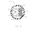
Figures 3 and4 show arrangements with three (3)tubes 14 and three (3)GRPs 18. However, as shown inFigures 5 and6 additional smaller versions ofcable 10 may employ the same features as described above for twenty four (24) fiber (Figure 5 ) and twelve (12) fiber (Figure 6 ) arrangements, with similar advantages provided with respect to shrinkage resistance at very cold temperatures (-60°C) and crush resistance. - The following tables 6 and 7 and relating to
Figures 5 and6 respectively both show that these designs forcable 10 have only a 0.06% cold temperature shrinkage between 23°C to 60°C while usingGRPs 18 that are sufficiently flexible to maintain the desired bend radius forcable 10.TABLE 6 2 tube 2 grp FRPVC jacket ID (mm) OD (mm) Qty Area E (N/m m^2) a AE AEa SUM AE SUM Aea a eff Temp 23 to -60 % contraction Tube (FRPVC) 2 3 2 7.9 90 7E-05 707 0.05 GRP 0 1.3 2 2.7 50000 6E-06 132732 0.79 Jacket FRPVC 6 8.3 1 25.8 90 7E-05 2325 0.17 Plastic To GRP Ratio 12.7 135764 1.01 7E-06 83 0.06% GRP flexible Bend Diameter (mm) = 100 x GRP Diameter 130 Typical Bend Cable Diameter is 20 X Cable OD 166 TABLE 7 1 tube 2 grp FRPVC jacket ID (mm) OD (mm) Qty Area E (N/m m^2) a AE AEa SUM AE SUM Aea a eff Temp 23 to -60 % -contraction Tube (FRPVC) 2 3 1 3.9 90 7E-05 353 0.03 GRP 0 1.3 2 2.7 50000 6E-06 132732 0.79 Jacket FRPVC 4.3 6.6 1 19.7 90 7E-05 1772 0.13 Plastic To GRP Ratio 8.9 134857.8 0.94 7E-06 83 0.06% GRP flexible Bend Diameter (mm) = 100 x GRP Diameter 130 Typical Bend Cable Diameter is 20 X Cable OD 132 - While only certain features of the invention have been illustrated and described herein, many modifications, substitutions, changes or equivalents will now occur to those skilled in the art. It is therefore, to be understood that this application is intended to cover all such modifications and changes that fall within the true spirit of the invention.
Claims (25)
- A fiber optic cable, said cable comprising:a plurality of buffer tubes each with one or more optical fibers, said buffer tubes having a first coefficient of contraction;a plurality of strength members, said strength members having a second coefficient of contraction; anda jacket, said jacket having a third coefficient of contraction,wherein the combined structure of said buffer tubes, said jacket and said strength members is such that said fibers within said buffer tubes meet maximum attenuation of substantially 0.07 db increase at -60°C.
- The fiber optic cable of claim 1, wherein the components of said buffer tubes and said strength members are SZ stranded.
- The fiber optic cable of claim 2, further comprising a binder around said strength members and said buffer tubes.
- The fiber optic cable of claim 3, wherein said buffer tubes and said strength members are SZ stranded at a lay length of a substantially 3-4 inches.
- The fiber optic cable of claim 4, wherein said binder is applied over said buffer tubes and strength members in a uni-directional helical lay of substantially 0.8 inches.
- The fiber optic cable of claim 1, wherein said buffer tubes further comprising aramid strength members.
- The fiber optic cable of claim 1, wherein said optical fibers are UV coated optical fibers.
- The fiber optic cable of claim 1, wherein said buffer tubes are made from FRPVC (Flame Resistant Polyvinyl Chloride).
- The fiber optic cable of claim 1, wherein said jacket is made from FRPVC (Flame Resistant Polyvinyl Chloride).
- The fiber optic cable of claim 1, wherein said jacket is made from PVDF (Polyvinylidene Fluoride).
- The fiber optic cable of claim 1, wherein said strength members are GRPs (Glass Reinforced Polymers).
- The fiber optic cable of claim 1, wherein there are three buffer tubes and three strength members.
- The fiber optic cable of claim 12, wherein said three buffer tubes are centered within said jacket and wherein said three strength members are positioned on the periphery nearer to said jacket.
- The fiber optic cable of claim 1, wherein there are two buffer tubes and two strength members.
- The fiber optic cable of claim 14, wherein said two buffer tubes are centered within said jacket and wherein said two strength members are positioned on the periphery nearer to said jacket.
- The fiber optic cable of claim 1, wherein there is one buffer tubes and two strength members.
- The fiber optic cable of claim 16, wherein said one buffer tube and said two strength members are all positioned on the periphery nearer to said jacket rather than any one component being centered.
- The fiber optic cable of claim 1, further comprising a filler within said jacket, configured to fill interstices between said buffer tubes and said strength members.
- The fiber optic cable of claim 18, wherein said filler fills in between 25% to 75% of said interstices.
- The fiber optic cable of claim 18, wherein said filler is selected from the group consisting of alumina trihydrate, magnesium hydroxide, hydrated mineral fillers and water swellable powder.
- The fiber optic cable of claim 18, wherein said cable is crush resistant to a force greater than 100N /cm.
- The fiber optic cable of claim 18, wherein a flexibility diameter equivalent of said strength members is less than a desired cable bend diameter and is in a plastic to strength member ratio in the range of 9.9 to 12.7 and wherein said contraction of said cable in a transition from -23°C to -60°C is less than 0.06%.
- A fiber optic cable, said cable comprising:at least one buffer tubes each with one or more optical fibers;at least one strength member; anda jacket extruded onto said at least one buffer tubes and said at least one strength members,wherein the arrangement of said at least one buffer tube and said at least one strength member within said jacket leaves certain void spaces in the interstices between said buffer tubes and said strength members, and wherein such interstices are filled with a fire retardant filler substance before the application of said jacket.
- The cable as claimed in claim 23 wherein said filler is Aluminum Tryhyd rate.
- A fiber optic cable, said cable comprising:at least one fiber element;a jacket extruded onto said at least one fiber element,wherein the arrangement of said at least one fiber element within said jacket leaves certain void spaces in the interstices between said fiber elements, wherein such interstices are filled with a fire retardant filler substance before the application of said jacket.
Applications Claiming Priority (1)
| Application Number | Priority Date | Filing Date | Title |
|---|---|---|---|
| US12/858,153 US8639076B2 (en) | 2010-08-17 | 2010-08-17 | Fiber optic cable with improved low temperature and compression resistance |
Publications (2)
| Publication Number | Publication Date |
|---|---|
| EP2420878A2 true EP2420878A2 (en) | 2012-02-22 |
| EP2420878A3 EP2420878A3 (en) | 2013-11-27 |
Family
ID=44719761
Family Applications (1)
| Application Number | Title | Priority Date | Filing Date |
|---|---|---|---|
| EP11305912.5A Withdrawn EP2420878A3 (en) | 2010-08-17 | 2011-07-13 | Fiber optic cable with improved low temperature and compression resistance |
Country Status (2)
| Country | Link |
|---|---|
| US (1) | US8639076B2 (en) |
| EP (1) | EP2420878A3 (en) |
Cited By (3)
| Publication number | Priority date | Publication date | Assignee | Title |
|---|---|---|---|---|
| EP2765444A1 (en) * | 2013-02-12 | 2014-08-13 | Nexans | Fiber optic cable with improved flexibility, low temperature and compression resistance |
| EP2820462A4 (en) * | 2012-03-02 | 2015-10-14 | Ofs Fitel Llc | FIBER OPTIC AIRCRAFT CABLES |
| CN105980902A (en) * | 2013-12-30 | 2016-09-28 | 康宁光电通信有限责任公司 | Binder film system |
Families Citing this family (10)
| Publication number | Priority date | Publication date | Assignee | Title |
|---|---|---|---|---|
| US8620124B1 (en) | 2012-09-26 | 2013-12-31 | Corning Cable Systems Llc | Binder film for a fiber optic cable |
| US11287589B2 (en) | 2012-09-26 | 2022-03-29 | Corning Optical Communications LLC | Binder film for a fiber optic cable |
| CN106104346A (en) * | 2013-12-30 | 2016-11-09 | 康宁光电通信有限责任公司 | There are the fiber optic cables of inflaming retarding membrane |
| US10126517B2 (en) * | 2014-06-10 | 2018-11-13 | Corning Optical Communications LLC | Fiber optic cable structured to facilitate accessing an end thereof |
| CN105044866A (en) * | 2015-08-06 | 2015-11-11 | 江苏中天科技股份有限公司 | Light-duty full medium self-supporting type optical cable |
| WO2017095542A1 (en) * | 2015-11-30 | 2017-06-08 | Corning Optical Communications LLC | Coextruded jacket for flame retardant fiber optic cables |
| EP3956704A4 (en) * | 2019-04-16 | 2023-01-11 | Corning Research & Development Corporation | PRE-TERMINATED CABLE ASSEMBLIES FOR INDOOR/OUTDOOR/DATA CENTER APPLICATIONS |
| US12032217B2 (en) * | 2019-08-07 | 2024-07-09 | Sterlite Technologies Limited | Cable with interstitial fillers and edge ribbons |
| WO2021247336A1 (en) * | 2020-06-01 | 2021-12-09 | Commscope Technologies Llc | Improved mechanical performance of optical stranded cables |
| CN113345628B (en) * | 2021-01-26 | 2022-12-13 | 陈跃超 | Special cable for mechanical equipment |
Family Cites Families (16)
| Publication number | Priority date | Publication date | Assignee | Title |
|---|---|---|---|---|
| US4839970A (en) * | 1985-07-05 | 1989-06-20 | Siemens Aktiengesellschaft | Filling compound for light waveguide leads and/or light waveguide cables |
| US5011880A (en) * | 1987-07-20 | 1991-04-30 | Northern Telecom Limited | Fire retardent and water blocking filling compositions for cables |
| US5390273A (en) | 1992-04-02 | 1995-02-14 | Pirelli Cable Corporation | Flame resistant optical fiber cable with optical fibers loosely enclosed in tubes |
| JP3282640B2 (en) | 1993-01-27 | 2002-05-20 | 日本電信電話株式会社 | Submarine optical cable |
| EP1916554A1 (en) | 1997-11-13 | 2008-04-30 | Nexans | Indoor/outdoor dry optical fiber cable |
| US6178278B1 (en) | 1997-11-13 | 2001-01-23 | Alcatel | Indoor/outdoor dry optical fiber cable |
| DE29816469U1 (en) * | 1998-09-14 | 1998-12-24 | Huang, Wen-Sheng, Tung Hsiao Chen, Miao Li | Steel rope structure with optical fibers |
| US7006740B1 (en) * | 1999-05-28 | 2006-02-28 | Corning Cable Systems, Llc | Communication cable having a soft housing |
| US6671441B1 (en) * | 2000-08-22 | 2003-12-30 | Fitel Usa Corp. | Optical cabling apparatus having improved dry filling compound and method for making |
| US6370303B1 (en) | 2000-10-20 | 2002-04-09 | Pirelli Cables And Systems Llc | Optical fiber cable with support member for indoor and outdoor use |
| AU2001219267A1 (en) * | 2000-11-27 | 2002-06-03 | Corning Cable Systems Llc | Communication cable containing novel filling material |
| KR100442687B1 (en) | 2002-04-30 | 2004-08-02 | 삼성전자주식회사 | Loose tube optical ribbon cable |
| WO2005041214A1 (en) * | 2003-09-30 | 2005-05-06 | Pirelli & C. S.P.A. | Cable with a coating layer made from a waste material |
| US7242831B2 (en) * | 2004-02-27 | 2007-07-10 | Verizon Business Global Llc | Low strain optical fiber cable |
| US7221831B2 (en) * | 2005-03-03 | 2007-05-22 | Nexans | Multi-tube fiber optic cable and system and method for making the same |
| US7664354B2 (en) | 2006-08-01 | 2010-02-16 | Nexans | System and method for loose tube tight buffer indoor/outdoor optical fiber cable |
-
2010
- 2010-08-17 US US12/858,153 patent/US8639076B2/en active Active
-
2011
- 2011-07-13 EP EP11305912.5A patent/EP2420878A3/en not_active Withdrawn
Non-Patent Citations (1)
| Title |
|---|
| None |
Cited By (6)
| Publication number | Priority date | Publication date | Assignee | Title |
|---|---|---|---|---|
| EP2820462A4 (en) * | 2012-03-02 | 2015-10-14 | Ofs Fitel Llc | FIBER OPTIC AIRCRAFT CABLES |
| EP2765444A1 (en) * | 2013-02-12 | 2014-08-13 | Nexans | Fiber optic cable with improved flexibility, low temperature and compression resistance |
| CN105980902A (en) * | 2013-12-30 | 2016-09-28 | 康宁光电通信有限责任公司 | Binder film system |
| US10191237B2 (en) | 2013-12-30 | 2019-01-29 | Corning Optical Communications LLC | Binder film system |
| CN105980902B (en) * | 2013-12-30 | 2019-05-28 | 康宁光电通信有限责任公司 | Binding film system |
| US10330877B2 (en) | 2013-12-30 | 2019-06-25 | Corning Optical Communications LLC | Binder film system |
Also Published As
| Publication number | Publication date |
|---|---|
| EP2420878A3 (en) | 2013-11-27 |
| US8639076B2 (en) | 2014-01-28 |
| US20120134634A1 (en) | 2012-05-31 |
Similar Documents
| Publication | Publication Date | Title |
|---|---|---|
| US8639076B2 (en) | Fiber optic cable with improved low temperature and compression resistance | |
| US6968106B2 (en) | Air blown fiber (ABF) cable with low composite coefficient of thermal expansion | |
| US8655127B2 (en) | Rugged fiber optic cable | |
| US9086556B2 (en) | Fiber optic cable with improved flexibility, low temperature and compression resistance | |
| US9488793B2 (en) | Combined optical fiber and power cable | |
| US10018796B1 (en) | Optical fiber ribbon assemblies with improved ribbon stack coupling | |
| US10983294B2 (en) | Deployable fiber optic cable with partially bonded ribbon fibers | |
| CN102197327A (en) | Fibre optic cable subunit assemblies | |
| US10591691B1 (en) | All-dielectric self-supporting fiber optic cable | |
| CN113366357A (en) | High density optical fiber ribbon cable | |
| CN113056690B (en) | Fiber optic cable with spoolable ribbon and central strength member | |
| EP3207415B1 (en) | Central loose tube optical-fiber cable | |
| KR102877251B1 (en) | Optical cable and flame retardant polyolefin composition for optical unit tube of the same | |
| US7346257B2 (en) | Buffer tubes with improved flexibility | |
| US20200319419A1 (en) | Optical Fiber Cables With Improved Burn And Smoke Performance | |
| US20220057587A1 (en) | Optical fiber cable jacket with low modulus of elasticity | |
| EP2312359A1 (en) | Optical-fiber cable having high fiber count and high fiber density | |
| US20080145009A1 (en) | Buffer tubes with improved flexibility | |
| US12276854B2 (en) | Flexible indoor/outdoor high-fiber-count cable | |
| EP2392957A1 (en) | Expanded four fiber unit cable design for increased fiber count cables having increased flexibility and fiber strength utilization | |
| JP2024503209A (en) | Fiber optic cable structure with rollable ribbon unit and elastomer layer | |
| WO2025117206A1 (en) | Optical fiber cable configured for low attenuation change during crush events |
Legal Events
| Date | Code | Title | Description |
|---|---|---|---|
| AK | Designated contracting states |
Kind code of ref document: A2 Designated state(s): AL AT BE BG CH CY CZ DE DK EE ES FI FR GB GR HR HU IE IS IT LI LT LU LV MC MK MT NL NO PL PT RO RS SE SI SK SM TR |
|
| AX | Request for extension of the european patent |
Extension state: BA ME |
|
| PUAI | Public reference made under article 153(3) epc to a published international application that has entered the european phase |
Free format text: ORIGINAL CODE: 0009012 |
|
| RIC1 | Information provided on ipc code assigned before grant |
Ipc: G02B 6/44 20060101AFI20130717BHEP |
|
| PUAL | Search report despatched |
Free format text: ORIGINAL CODE: 0009013 |
|
| AK | Designated contracting states |
Kind code of ref document: A3 Designated state(s): AL AT BE BG CH CY CZ DE DK EE ES FI FR GB GR HR HU IE IS IT LI LT LU LV MC MK MT NL NO PL PT RO RS SE SI SK SM TR |
|
| AX | Request for extension of the european patent |
Extension state: BA ME |
|
| RIC1 | Information provided on ipc code assigned before grant |
Ipc: G02B 6/44 20060101AFI20131023BHEP |
|
| 17P | Request for examination filed |
Effective date: 20140509 |
|
| RBV | Designated contracting states (corrected) |
Designated state(s): AL AT BE BG CH CY CZ DE DK EE ES FI FR GB GR HR HU IE IS IT LI LT LU LV MC MK MT NL NO PL PT RO RS SE SI SK SM TR |
|
| 17Q | First examination report despatched |
Effective date: 20151027 |
|
| GRAP | Despatch of communication of intention to grant a patent |
Free format text: ORIGINAL CODE: EPIDOSNIGR1 |
|
| INTG | Intention to grant announced |
Effective date: 20160607 |
|
| GRAJ | Information related to disapproval of communication of intention to grant by the applicant or resumption of examination proceedings by the epo deleted |
Free format text: ORIGINAL CODE: EPIDOSDIGR1 |
|
| GRAP | Despatch of communication of intention to grant a patent |
Free format text: ORIGINAL CODE: EPIDOSNIGR1 |
|
| INTC | Intention to grant announced (deleted) | ||
| INTG | Intention to grant announced |
Effective date: 20161109 |
|
| STAA | Information on the status of an ep patent application or granted ep patent |
Free format text: STATUS: THE APPLICATION IS DEEMED TO BE WITHDRAWN |
|
| 18D | Application deemed to be withdrawn |
Effective date: 20170321 |