EP2420753A1 - Air conditioning device - Google Patents
Air conditioning device Download PDFInfo
- Publication number
- EP2420753A1 EP2420753A1 EP10764477A EP10764477A EP2420753A1 EP 2420753 A1 EP2420753 A1 EP 2420753A1 EP 10764477 A EP10764477 A EP 10764477A EP 10764477 A EP10764477 A EP 10764477A EP 2420753 A1 EP2420753 A1 EP 2420753A1
- Authority
- EP
- European Patent Office
- Prior art keywords
- airflow
- air outlet
- heat exchanger
- air
- wall portion
- Prior art date
- Legal status (The legal status is an assumption and is not a legal conclusion. Google has not performed a legal analysis and makes no representation as to the accuracy of the status listed.)
- Withdrawn
Links
- 238000004378 air conditioning Methods 0.000 title description 9
- 238000007664 blowing Methods 0.000 claims abstract description 21
- 238000007599 discharging Methods 0.000 claims abstract description 4
- 238000001816 cooling Methods 0.000 description 6
- 230000015572 biosynthetic process Effects 0.000 description 5
- 230000005494 condensation Effects 0.000 description 5
- 238000009833 condensation Methods 0.000 description 5
- 238000010438 heat treatment Methods 0.000 description 4
- 239000003507 refrigerant Substances 0.000 description 4
- 238000005192 partition Methods 0.000 description 3
- 230000000903 blocking effect Effects 0.000 description 2
- 230000001143 conditioned effect Effects 0.000 description 2
- 238000010276 construction Methods 0.000 description 2
- 238000009413 insulation Methods 0.000 description 2
- 230000009471 action Effects 0.000 description 1
- 230000000694 effects Effects 0.000 description 1
- 230000007246 mechanism Effects 0.000 description 1
- 238000000034 method Methods 0.000 description 1
- 230000000149 penetrating effect Effects 0.000 description 1
- 230000008569 process Effects 0.000 description 1
- 230000009467 reduction Effects 0.000 description 1
- 238000011144 upstream manufacturing Methods 0.000 description 1
- XLYOFNOQVPJJNP-UHFFFAOYSA-N water Substances O XLYOFNOQVPJJNP-UHFFFAOYSA-N 0.000 description 1
Images



Classifications
-
- F—MECHANICAL ENGINEERING; LIGHTING; HEATING; WEAPONS; BLASTING
- F24—HEATING; RANGES; VENTILATING
- F24F—AIR-CONDITIONING; AIR-HUMIDIFICATION; VENTILATION; USE OF AIR CURRENTS FOR SCREENING
- F24F1/00—Room units for air-conditioning, e.g. separate or self-contained units or units receiving primary air from a central station
- F24F1/0007—Indoor units, e.g. fan coil units
- F24F1/0011—Indoor units, e.g. fan coil units characterised by air outlets
-
- F—MECHANICAL ENGINEERING; LIGHTING; HEATING; WEAPONS; BLASTING
- F24—HEATING; RANGES; VENTILATING
- F24F—AIR-CONDITIONING; AIR-HUMIDIFICATION; VENTILATION; USE OF AIR CURRENTS FOR SCREENING
- F24F1/00—Room units for air-conditioning, e.g. separate or self-contained units or units receiving primary air from a central station
- F24F1/0007—Indoor units, e.g. fan coil units
- F24F1/0043—Indoor units, e.g. fan coil units characterised by mounting arrangements
- F24F1/0047—Indoor units, e.g. fan coil units characterised by mounting arrangements mounted in the ceiling or at the ceiling
-
- F—MECHANICAL ENGINEERING; LIGHTING; HEATING; WEAPONS; BLASTING
- F24—HEATING; RANGES; VENTILATING
- F24F—AIR-CONDITIONING; AIR-HUMIDIFICATION; VENTILATION; USE OF AIR CURRENTS FOR SCREENING
- F24F1/00—Room units for air-conditioning, e.g. separate or self-contained units or units receiving primary air from a central station
- F24F1/0007—Indoor units, e.g. fan coil units
- F24F1/0043—Indoor units, e.g. fan coil units characterised by mounting arrangements
- F24F1/0057—Indoor units, e.g. fan coil units characterised by mounting arrangements mounted in or on a wall
-
- F—MECHANICAL ENGINEERING; LIGHTING; HEATING; WEAPONS; BLASTING
- F24—HEATING; RANGES; VENTILATING
- F24F—AIR-CONDITIONING; AIR-HUMIDIFICATION; VENTILATION; USE OF AIR CURRENTS FOR SCREENING
- F24F13/00—Details common to, or for air-conditioning, air-humidification, ventilation or use of air currents for screening
- F24F13/08—Air-flow control members, e.g. louvres, grilles, flaps or guide plates
- F24F13/082—Grilles, registers or guards
- F24F2013/088—Air-flow straightener
Definitions
- the present invention relates to an air conditioner discharging conditioned air into a room. More particularly, the present invention relates to an air conditioner that can discharge from an air outlet an airflow widened in a longitudinal direction of the air outlet.
- Patent Literature 1 discloses an air conditioner including a ceiling-suspended indoor unit.
- the indoor unit of this air conditioner includes: a body casing including an air outlet on a front side thereof; a heat exchanger accommodated in a front portion of the body casing; and an air blowing fan accommodated in a rear portion of the body casing.
- the air blowing fan suctions air from a lower side of the body casing and blows forward the suctioned air.
- the heat exchanger performs heat exchange by letting therethrough the airflow blown forward by the air blowing fan.
- the air heated or cooled through the heat exchange process is discharged from the air outlet into the room whereby room temperature and the like are conditioned.
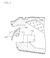
- FIG.7 is a sectional side view showing in enlarged dimension the vicinity of the air outlet of the indoor unit of the prior-art air conditioner (Patent Literature 1).
- the airflow blade includes a vertical blade 135 for transverse adjustment of the airflow direction and a horizontal blade 136 disposed forwardly of the vertical blade 135 and making vertical adjustment of the airflow direction.
- the horizontal blade 136 is in a level position (indicated by a chain double-dashed line in the figure) thereby directing a cool airflow forward.
- the horizontal blade is in a downward position (indicated by a solid line in the figure) thereby directing a warm airflow forward and obliquely downward.
- the horizontal blade promotes air convection in the room by vertically adjusting the airflow direction according to its operation mode for cooling or heating.
- the air conditioner can achieve effective air conditioning.
- the vertical blade 135 delivers a wide airflow into the room particularly by adjustably directing the airflow outward in the transverse direction. The vertical blade contributes to effective air conditioning of the entire room.
- Patent Literature 1 has the following problem.
- a rear end 136a of the horizontal blade 136 is positioned higher than the vertical blade 135, as shown in FIG.7 .
- the present invention has an object to provide an air conditioner that can discharge from its air outlet an airflow widened outward in the longitudinal direction of the air outlet and can obviate uneven air conditioning of the room.
- An air conditioner of the present invention comprises: a heat exchanger; an air blowing device for generating an airflow passing through the heat exchanger; a body casing accommodating the heat exchanger and the air blowing device and including an elongated air outlet for discharging the airflow having passed through the heat exchanger; and an airflow shield member provided at a longitudinal end portion of the air outlet, the airflow shield member covering the heat exchanger on the air outlet side and thereby diverting the airflow having passed through the heat exchanger inwardly in the longitudinal direction before guiding the airflow toward the end portion of the air outlet.
- the airflow generated by the air blowing device passes through the heat exchanger and then collides against the airflow shield member at the longitudinal end portion of the air outlet so as to be diverted longitudinally inwardly. Thereafter, the airflow passes the airflow shield member and blows toward the air outlet. Then a low pressure region which is substantially in no-airflow state is formed in front of the shield member, so that the air having passed the airflow shield member and flowing toward the air outlet is directed outward in the longitudinal direction of the air outlet as drawn into the low pressure region.
- This drawing action generates an airflow spread longitudinally outward from the air outlet, thereby the uneven air conditioning of the room can be obviated.
- the air conditioner according to the present invention can discharge from the air outlet the airflow widened outward in the longitudinal direction of the air outlet, thus obviating the uneven air conditioning of the room.
- FIG.1 is a front view showing an indoor unit 10 of an air conditioner according to the embodiment of the present invention.
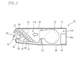
- FIG.2 is a schematic sectional view of the indoor unit 10 shown in FIG.1 .
- FIG.3 is a schematic plan view showing an internal construction of the indoor unit shown in FIG.1 .
- the indoor unit 10 is of a ceiling-suspended type and includes a body casing 11 formed in a box shape elongated in a transverse direction and short in a vertical direction.
- the body casing 11 accommodates a plurality of air blowing fans (air blowing devices) 12, a heat exchanger 13, a fan driving motor (driving portion) 14 and the like.
- the body casing 11 includes: a top panel portion 16 suspendable from a ceiling; a bottom panel portion 17 disposed under a front portion of the top panel portion 16 in opposed relation thereto; a grille cover 18 disposed under a rear portion of the top panel portion 16 in opposed relation thereto; and side portion covers 19 (see FIG.1 ) disposed on transversely opposite sides of the top panel portion 16, the bottom panel portion 17 and the grille cover 18.
- a rear end of the top panel portion 16 is bent downward so as to define a rear panel portion 16a.
- the grille cover 18 is formed with an air inlet 20 for taking room air into the body casing 11.
- a partition plate 21 vertically upstands between the bottom panel portion 17 and the grille cover 18, dividing the interior of the body casing 11 into front and rear spaces 11A, 11B.
- the body casing 11 is formed with an air outlet 22 on a front side thereof.
- the air outlet has a transversely elongated rectangular shape and defines an opening to the front.
- the air blowing fans 12 are transversely arranged in the rear space 11B of the body casing 11 and supported by the partition plate 21.
- Each of the air blowing fans 12 is a multiblade fan such as a sirocco fan.
- Each of the air blowing fans 12 is driven by the motor 14.
- the air blowing fan 12 is designed to suction the room air through the air inlet 20 (see FIG.2 ) formed in a bottom of a rear portion of the body casing 11, thus generating airflow into the space 11A forward of the partition plate 21.
- the heat exchanger 13 is disposed in the front space 11A of the body casing 11 and designed to let through a forward airflow generated by the air blowing fans 12.
- the heat exchanger 13 includes multitudes of fins 25 transversely arranged with predetermined spacing, and refrigerant piping 26 transversely extends as penetrating the fins 25.
- the heat exchanger 13 has a length spanning most of the transverse range of the interior space of the body casing 11. The heat exchanger is placed slightly nearer one transverse side of the body casing (to the left side as seen in the figure) as viewed from the front.
- components 27 such as piping for refrigerant circulation between the indoor unit and an outdoor unit are provided in adjoining relation with the heat exchanger 13.
- the air blowing fans 12 are transversely distributed so as to deliver the airflow to the entire transverse range of the heat exchanger 13.
- the air conditioner is capable of performing a cooling operation by using the heat exchanger 13 as an evaporator and a heating operation by using the heat exchanger 13 as a condenser.
- the heat exchanger 13 is disposed at an angle with respect to the top panel portion 16 or the bottom panel portion 17 of the body casing 11 in a manner that an upper part thereof is located forward (closer to the air outlet 22; on a downstream side of the airflow) while a lower part thereof is located rearward (closer to the air blowing fans 12; on an upstream side of the airflow).
- the airflow driven forward by the air blowing fans 12 passes through the heat exchanger 13 whereby the air exchanges heat with a refrigerant flowing through the refrigerant piping 26.
- the resultant airflow is discharged as turned in a forward and obliquely downward direction, that is, substantially perpendicularly to the heat exchanger 13.
- the top panel portion 16 is provided with a heat insulation 30 at a lower surface of a front end portion thereof.
- An upper wall portion 31 of the air outlet 22 is defined by this insulation 30.
- Disposed on the upper surface of the bottom panel portion 17 is a drain pan 32 for receiving condensation water generated at the heat exchanger 13.
- a lower wall portion 33 of the air outlet 22 is defined by a front edge portion of the drain pan 32.
- a lower surface of the upper wall portion 31 is inclined in a direction substantially perpendicular to the heat exchanger 13. Accordingly, the air having passed through the heat exchanger 13 and flowing in the direction substantially perpendicular to the heat exchanger 13 is reduced in flow resistance and turbulence when moving along the upper wall portion 31 to pass through the air outlet 22.
- the reduction in volume of the air discharged from the air outlet 22 can be obviated in this manner.
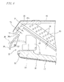
- the air outlet 22 is provided with an airflow adjustment blade for adjusting the direction (wind direction) of airflow discharged from the air outlet 22 after having passed through the heat exchanger 13.
- the airflow adjustment blade includes a vertical blade (first adjustment blade) 35 for transverse adjustment of the wind direction and a horizontal blade (second adjustment blade) 36 disposed forwardly of the vertical blade 35 and making vertical adjustment of the wind direction.
- each of vertical blades 35 is arranged substantially in the entire longitudinal range of the air outlet 22.
- the vertical blades 35 are each mounted to the lower wall portion 33 in a manner to be transversely swingable about a first vertical axis X1.
- a given number (e.g. four) of adjoining vertical blades 35 are interconnected via an interlocking member 39 such that these interconnected vertical blades 35 may swing simultaneously in the same direction.
- the horizontal blade 36 has a length spanning substantially the entire longitudinal range of the air outlet 22.
- the horizontal blade 36 is mounted via an unillustrated support member in a manner to be vertically swingable about a second axis X2 extending in the transverse direction.
- the horizontal blade 36 is driven into the swing motion by an unillustrated motor or link mechanism.
- the horizontal blade 36 is movable between a level position, indicated by a chain double-dashed line in FIG.4 , as an upper limit of the swing motion for adjustment of the wind direction and a downward position, indicated by a solid line in the figure, as a lower limit of the swing motion for adjustment of the wind direction.
- the horizontal blade can be moved between these positions to make the vertical adjustment of the airflow direction.
- the horizontal blade 36 is curved such that the horizontal blade, when in the level position, is convex upward as seen in side view.
- the air outlet 22 is provided with an airflow shield member 43 at one transverse end portion thereof (the left end portion) for blocking the air flowing toward the air outlet 22 after having passed through the heat exchanger 13.
- the airflow shield member 43 is a rectangular plate.
- the airflow shield member is inclined in a manner that an upper part thereof is located forward.
- the airflow shield member is disposed forwardly of the heat exchanger 13 and extends substantially in parallel to the heat exchanger with a gap t defined therebetween.
- a gap T1 is also defined between an upper end of the airflow shield member 43 and the upper wall portion 31.
- the air outlet 22 is provided with a blind plate (covering member) 45 at the other transverse end portion thereof (the right end portion), the blind plate covering the components 27 such as piping from the front side to keep the components out of sight.
- FIG.5 is a schematic plan view showing an interior of the air outlet 22 at a left end portion of the air conditioner.
- the air flowing forward through the heat exchanger 13 is blocked by the airflow shield member 43 so as to be guided rightward along a back side of the airflow shield member 43 (see an arrow a in the figure).
- the airflow directed rightward to pass by the back side of the airflow shield member 43 is redirected forward (see an arrow b in the figure). In this manner, the airflow shield member 43 functions to divert the airflow having passed through the heat exchanger 13 transversely inwardly.
- a low pressure region A1 which is substantially in no-airflow state is formed in front of the airflow shield member 43, as a result of blocking the airflow coming from the heat exchanger 13 side. Therefore, the airflow moving forward after passing by the airflow shield member 43 is turned leftward as drawn into the low pressure region A1, before discharged from the air outlet 22 (see an arrow c in the figure). Thus, a wide airflow spread leftward from the air outlet 22 can be formed without relying on the vertical blades 35.
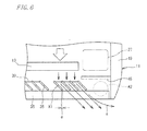
- FIG.6 is a schematic plan view showing an interior of the air outlet 22 at a right end portion of the air conditioner.
- the components 27 such as piping are disposed within the body casing 11 at the right end thereof.
- the air outlet 22 is provided with the blind plate 45 as the covering member in order to prevent the components 27 from being exposed on the air outlet 22 side.
- a low pressure region A2 which is substantially in no-airflow state is formed in front of the blind plate 45. Therefore, the airflow moving forward after passing through the heat exchanger 13 and then passing along the left side of the blind plate 45 is turned rightward as drawn into the low pressure region A2, before discharged from the air outlet 22 (see an arrow d in the figure). In this manner, a wide airflow spread rightward from the air outlet 22 can be formed without relying on the vertical blades 35.
- the air outlet 22 is provided with the airflow shield member 43 at the left end portion thereof and with the blind plate 45 at the right end portion thereof, so that the airflow is discharged from the air outlet 22 as spread wide in transversely opposite directions. Therefore, uneven air conditioning of the room can be obviated.
- the vertical blades 35 are adapted to swing in the transverse direction.
- a front-back end portion of one vertical blade 35 transversely overlaps with the other front-back end portion of its adjoining vertical blade 35 by an overlap width e. This ensures that the air flowing forward after passing through the heat exchanger 13 inevitably collides against the vertical blades 35 so as to be adjusted in the flow direction instead of being allowed to move straight ahead.
- the vertical blades 35 When swung to the rightmost or leftmost position, therefore, the vertical blades 35 become capable of transversely widening the airflow, and accordingly functions, together with the above-described airflow shield member 43 and blind plate 45, to obviate the uneven air conditioning of the room.
- the vertical blade 35 is formed to be substantially level with a rear end 36a of the horizontal blade 36 in the most downward position as indicated by a solid line in FIG.4 . Therefore, the airflow directed downward as passing under the horizontal blade 36 is also transversely adjusted in direction by the vertical blades 35. Hence, the airflow can be discharged in a transversely wider range by adjusting the vertical blades 35 to turn transversely outward.
- a gap T2 between the rear end 36a of the horizontal blade 36 in the most downward position and the upper wall portion 31 of the air outlet 22 is substantially equal to the gap T1 between an upper end 43a of the airflow shield member 43 and the upper wall portion 31 of the air outlet 22.
- the air (cool air) from the heat exchanger 13 having passed over the airflow shield member 43 flows though the gap T2 and along an upper surface of the horizontal blade 36.
- the airflow along the upper surface of the horizontal blade 36 forms on the upper surface a cold-air seal of a cold air layer, which can prevent the formation of condensation on the upper surface of the horizontal blade.
- the embodiment of the present invention can obviate such a problem.
- the present invention is not limited to the above-described embodiment and permits appropriate design choices.
- the present invention is also applicable to air conditioners besides the air conditioner including the ceiling suspended indoor unit 10.
- the present invention may be applied to an air conditioner including, for example, a ceiling mounted indoor unit having a downward-oriented air outlet.
- the location of the airflow shield member 43 according to the above-described embodiment is not limited to one longitudinal end of the air outlet 22.
- the air outlet 22 may also be provided with the airflow shield members at both longitudinally opposite end portions thereof.
- the blind plate 45 may be extended inward in the longitudinal direction of the air outlet 22 so that the extended portion may be located in front of the heat exchanger 13 to serve as the airflow shield member.
Landscapes
- Engineering & Computer Science (AREA)
- Chemical & Material Sciences (AREA)
- Combustion & Propulsion (AREA)
- Mechanical Engineering (AREA)
- General Engineering & Computer Science (AREA)
- Air-Flow Control Members (AREA)
- Air Filters, Heat-Exchange Apparatuses, And Housings Of Air-Conditioning Units (AREA)
Abstract
Description
- The present invention relates to an air conditioner discharging conditioned air into a room. More particularly, the present invention relates to an air conditioner that can discharge from an air outlet an airflow widened in a longitudinal direction of the air outlet.
- The following Patent Literature 1 discloses an air conditioner including a ceiling-suspended indoor unit. The indoor unit of this air conditioner includes: a body casing including an air outlet on a front side thereof; a heat exchanger accommodated in a front portion of the body casing; and an air blowing fan accommodated in a rear portion of the body casing. The air blowing fan suctions air from a lower side of the body casing and blows forward the suctioned air. The heat exchanger performs heat exchange by letting therethrough the airflow blown forward by the air blowing fan. The air heated or cooled through the heat exchange process is discharged from the air outlet into the room whereby room temperature and the like are conditioned.
- On the other hand, the body casing is provided with an airflow adjustment blade at the air outlet thereof for making adjustment of airflow direction.
FIG.7 is a sectional side view showing in enlarged dimension the vicinity of the air outlet of the indoor unit of the prior-art air conditioner (Patent Literature 1). The airflow blade includes avertical blade 135 for transverse adjustment of the airflow direction and ahorizontal blade 136 disposed forwardly of thevertical blade 135 and making vertical adjustment of the airflow direction. - During a cooling operation, for example, the
horizontal blade 136 is in a level position (indicated by a chain double-dashed line in the figure) thereby directing a cool airflow forward. During a heating operation, the horizontal blade is in a downward position (indicated by a solid line in the figure) thereby directing a warm airflow forward and obliquely downward. The horizontal blade promotes air convection in the room by vertically adjusting the airflow direction according to its operation mode for cooling or heating. Thus, the air conditioner can achieve effective air conditioning.
Thevertical blade 135 delivers a wide airflow into the room particularly by adjustably directing the airflow outward in the transverse direction. The vertical blade contributes to effective air conditioning of the entire room. -
- [Patent Literature 1] Japanese Unexamined Patent Publication No.
2002-106882 FIG.1 ) - The indoor unit disclosed in Patent Literature 1 has the following problem. In a case where the
horizontal blade 136 is in a downward position during heating operation or the like, arear end 136a of thehorizontal blade 136 is positioned higher than thevertical blade 135, as shown inFIG.7 . This disables thevertical blade 135 to adjust the direction of the airflow passing over it, and therefore the vertical blade fails to form transversely widened airflow. This results in an increased likelihood of uneven air conditioning of the room and increased time to even out the room temperature. - In view of the above, the present invention has an object to provide an air conditioner that can discharge from its air outlet an airflow widened outward in the longitudinal direction of the air outlet and can obviate uneven air conditioning of the room.
- (1) An air conditioner of the present invention comprises: a heat exchanger; an air blowing device for generating an airflow passing through the heat exchanger; a body casing accommodating the heat exchanger and the air blowing device and including an elongated air outlet for discharging the airflow having passed through the heat exchanger; and an airflow shield member provided at a longitudinal end portion of the air outlet, the airflow shield member covering the heat exchanger on the air outlet side and thereby diverting the airflow having passed through the heat exchanger inwardly in the longitudinal direction before guiding the airflow toward the end portion of the air outlet.
- According to the present invention described above, the airflow generated by the air blowing device passes through the heat exchanger and then collides against the airflow shield member at the longitudinal end portion of the air outlet so as to be diverted longitudinally inwardly. Thereafter, the airflow passes the airflow shield member and blows toward the air outlet. Then a low pressure region which is substantially in no-airflow state is formed in front of the shield member, so that the air having passed the airflow shield member and flowing toward the air outlet is directed outward in the longitudinal direction of the air outlet as drawn into the low pressure region. This drawing action generates an airflow spread longitudinally outward from the air outlet, thereby the uneven air conditioning of the room can be obviated.
-
- (2) In the above constitution, it is preferred that the airflow shield member is placed on the air outlet side with respect to the heat exchanger at a distance therefrom. According to this arrangement, the airflow having passed through the heat exchanger moves along a back side of the airflow shield member and is smoothly diverted inward in the longitudinal direction of the air outlet. Thus, an adequate volume of airflow can be discharged from the air outlet, in contrast to a case where the airflow shield member is closely spaced from the heat exchanger.
-
- (3) It is preferred that a covering member is provided at a longitudinally opposite end portion of the air outlet from the airflow shield member and covers a component on the air outlet side, the component adjoining the heat exchanger in the longitudinal direction. Because of the provision of such a covering member, a low pressure region which is substantially in no-airflow state is formed in front of the covering member, so that the air passing the covering member inward in the longitudinal direction of the air outlet is directed outward in the longitudinal direction of the air outlet as drawn into the low pressure region. Thus is generated an airflow spread longitudinally outward from the air outlet.
-
- (4) It is preferred that the air outlet is provided with a plurality of first adjustment blades swingable in the longitudinal direction for adjusting the longitudinal direction of the airflow discharged from the air outlet, and that the first adjustment blades are arranged in a manner that, when they are swung maximally, one first adjustment blade has its one end portion overlapped with the other end portion of its adjoining first adjustment blade in the longitudinal direction of the air outlet.
-
- (5) It is preferred that the air outlet includes a lower wall portion and an upper wall portion opposed to each other in a direction orthogonal to the longitudinal direction of the air outlet, that a second adjustment blade is provided between the lower wall portion and the upper wall portion for vertically adjusting the direction of the airflow discharged from the air outlet, and that the airflow shield member is spaced a distance from the upper wall portion.
-
- (6) It is preferred that the distance from the airflow shield member to the upper wall portion is substantially equal to a distance from an upper end of the second adjustment blade in the most downward position to the upper wall portion. When the second adjustment blade is adjusted to the most downward position, the upper end of the second adjustment blade generally comes closest to the upper wall portion of the air outlet. Even so, a gap substantially equal to the distance from the airflow shield member to the upper wall portion is defined between the upper end of the second adjustment blade and the upper wall portion, facilitating the passage of the air over the second adjustment blade in the most downward position. Accordingly, the cold-air seal can be favorably formed on the upper surface of the second adjustment blade, preventing the formation of condensation.
-
- (7) It is preferred that the air outlet includes a lower wall portion and an upper wall portion opposed to each other in a direction orthogonal to the longitudinal direction of the air outlet, that a first adjustment blade for adjusting the longitudinal direction of the airflow discharged from the air outlet and a second adjustment blade for adjusting the vertical direction of the airflow are provided between the lower wall portion and the upper wall portion, and that the first adjustment blade is substantially level with an upper end of the second adjustment blade adjusted to the most downward position.
-
- (8) It is preferred that the heat exchanger is inclined in a manner that an upper part thereof is located forward in an airflow discharge direction and a lower part thereof is located rearward in the airflow discharge direction, and that the upper wall portion is formed substantially perpendicularly to the heat exchanger.
- The air conditioner according to the present invention can discharge from the air outlet the airflow widened outward in the longitudinal direction of the air outlet, thus obviating the uneven air conditioning of the room.
-
- [
FIG.1 ]
FIG.1 is a front view showing an indoor unit of an air conditioner according to an embodiment of the present invention; - [
FIG.2 ]
FIG.2 is a schematic sectional view of the indoor unit shown inFIG.1 ; - [
FIG.3 ]
FIG.3 is a schematic plan view showing an internal construction of the indoor unit shown inFIG.1 ; - [
FIG.4 ]
FIG.4 is a schematic sectional view showing in enlarged dimension the vicinity of an air outlet of the indoor unit shown inFIG.1 ; - [
FIG.5 ]
FIG. 5 is a schematic plan view showing in enlarged dimension one transverse end portion of the interior of the indoor unit shown inFIG.1 ; - [
FIG.6 ]
FIG.6 is a schematic plan view showing in enlarged dimension the other transverse end portion of the interior of the indoor unit shown inFIG.1 ; and - [
FIG.7 ]
FIG.7 is a schematic sectional view showing in enlarged dimension the vicinity of an air outlet of a prior-art air conditioner. - An embodiment of the present invention will be described as below with reference to the accompanying drawings.
FIG.1 is a front view showing anindoor unit 10 of an air conditioner according to the embodiment of the present invention.FIG.2 is a schematic sectional view of theindoor unit 10 shown inFIG.1 .FIG.3 is a schematic plan view showing an internal construction of the indoor unit shown inFIG.1 . Theindoor unit 10 is of a ceiling-suspended type and includes abody casing 11 formed in a box shape elongated in a transverse direction and short in a vertical direction. Thebody casing 11 accommodates a plurality of air blowing fans (air blowing devices) 12, aheat exchanger 13, a fan driving motor (driving portion) 14 and the like. - As shown in
FIG.2 , thebody casing 11 includes: atop panel portion 16 suspendable from a ceiling; abottom panel portion 17 disposed under a front portion of thetop panel portion 16 in opposed relation thereto; agrille cover 18 disposed under a rear portion of thetop panel portion 16 in opposed relation thereto; and side portion covers 19 (seeFIG.1 ) disposed on transversely opposite sides of thetop panel portion 16, thebottom panel portion 17 and thegrille cover 18. A rear end of thetop panel portion 16 is bent downward so as to define arear panel portion 16a. Thegrille cover 18 is formed with anair inlet 20 for taking room air into thebody casing 11. Apartition plate 21 vertically upstands between thebottom panel portion 17 and thegrille cover 18, dividing the interior of thebody casing 11 into front andrear spaces body casing 11 is formed with anair outlet 22 on a front side thereof. The air outlet has a transversely elongated rectangular shape and defines an opening to the front. - As shown in
FIG.3 , theair blowing fans 12 are transversely arranged in therear space 11B of thebody casing 11 and supported by thepartition plate 21. Each of theair blowing fans 12 is a multiblade fan such as a sirocco fan. Each of theair blowing fans 12 is driven by themotor 14. Theair blowing fan 12 is designed to suction the room air through the air inlet 20 (seeFIG.2 ) formed in a bottom of a rear portion of thebody casing 11, thus generating airflow into thespace 11A forward of thepartition plate 21. - As shown in
FIG.3 , theheat exchanger 13 is disposed in thefront space 11A of thebody casing 11 and designed to let through a forward airflow generated by theair blowing fans 12. Theheat exchanger 13 includes multitudes offins 25 transversely arranged with predetermined spacing, andrefrigerant piping 26 transversely extends as penetrating thefins 25. Theheat exchanger 13 has a length spanning most of the transverse range of the interior space of thebody casing 11. The heat exchanger is placed slightly nearer one transverse side of the body casing (to the left side as seen in the figure) as viewed from the front. On the other transverse side of the body casing (the right side as seen in the figure),components 27 such as piping for refrigerant circulation between the indoor unit and an outdoor unit are provided in adjoining relation with theheat exchanger 13. Theair blowing fans 12 are transversely distributed so as to deliver the airflow to the entire transverse range of theheat exchanger 13. The air conditioner is capable of performing a cooling operation by using theheat exchanger 13 as an evaporator and a heating operation by using theheat exchanger 13 as a condenser. - As shown in
FIG.2 , theheat exchanger 13 is disposed at an angle with respect to thetop panel portion 16 or thebottom panel portion 17 of thebody casing 11 in a manner that an upper part thereof is located forward (closer to theair outlet 22; on a downstream side of the airflow) while a lower part thereof is located rearward (closer to theair blowing fans 12; on an upstream side of the airflow). The airflow driven forward by theair blowing fans 12 passes through theheat exchanger 13 whereby the air exchanges heat with a refrigerant flowing through therefrigerant piping 26. The resultant airflow is discharged as turned in a forward and obliquely downward direction, that is, substantially perpendicularly to theheat exchanger 13. - The
top panel portion 16 is provided with aheat insulation 30 at a lower surface of a front end portion thereof. Anupper wall portion 31 of theair outlet 22 is defined by thisinsulation 30. Disposed on the upper surface of thebottom panel portion 17 is adrain pan 32 for receiving condensation water generated at theheat exchanger 13. Alower wall portion 33 of theair outlet 22 is defined by a front edge portion of thedrain pan 32. A lower surface of theupper wall portion 31 is inclined in a direction substantially perpendicular to theheat exchanger 13. Accordingly, the air having passed through theheat exchanger 13 and flowing in the direction substantially perpendicular to theheat exchanger 13 is reduced in flow resistance and turbulence when moving along theupper wall portion 31 to pass through theair outlet 22. The reduction in volume of the air discharged from theair outlet 22 can be obviated in this manner. - The
air outlet 22 is provided with an airflow adjustment blade for adjusting the direction (wind direction) of airflow discharged from theair outlet 22 after having passed through theheat exchanger 13. The airflow adjustment blade includes a vertical blade (first adjustment blade) 35 for transverse adjustment of the wind direction and a horizontal blade (second adjustment blade) 36 disposed forwardly of thevertical blade 35 and making vertical adjustment of the wind direction. - As shown in
FIG.3 , multitudes ofvertical blades 35 are arranged substantially in the entire longitudinal range of theair outlet 22. Thevertical blades 35 are each mounted to thelower wall portion 33 in a manner to be transversely swingable about a first vertical axis X1. A given number (e.g. four) of adjoiningvertical blades 35 are interconnected via an interlockingmember 39 such that these interconnectedvertical blades 35 may swing simultaneously in the same direction. - The
horizontal blade 36 has a length spanning substantially the entire longitudinal range of theair outlet 22. Thehorizontal blade 36 is mounted via an unillustrated support member in a manner to be vertically swingable about a second axis X2 extending in the transverse direction. Thehorizontal blade 36 is driven into the swing motion by an unillustrated motor or link mechanism. Thehorizontal blade 36 is movable between a level position, indicated by a chain double-dashed line inFIG.4 , as an upper limit of the swing motion for adjustment of the wind direction and a downward position, indicated by a solid line in the figure, as a lower limit of the swing motion for adjustment of the wind direction. The horizontal blade can be moved between these positions to make the vertical adjustment of the airflow direction. Thehorizontal blade 36 is curved such that the horizontal blade, when in the level position, is convex upward as seen in side view. - As shown in
FIG.1 andFIG.3 , theair outlet 22 is provided with anairflow shield member 43 at one transverse end portion thereof (the left end portion) for blocking the air flowing toward theair outlet 22 after having passed through theheat exchanger 13. Theairflow shield member 43 is a rectangular plate. As shown inFIG.4 , the airflow shield member is inclined in a manner that an upper part thereof is located forward. The airflow shield member is disposed forwardly of theheat exchanger 13 and extends substantially in parallel to the heat exchanger with a gap t defined therebetween. Furthermore, a gap T1 is also defined between an upper end of theairflow shield member 43 and theupper wall portion 31.
Theair outlet 22 is provided with a blind plate (covering member) 45 at the other transverse end portion thereof (the right end portion), the blind plate covering thecomponents 27 such as piping from the front side to keep the components out of sight. -
FIG.5 is a schematic plan view showing an interior of theair outlet 22 at a left end portion of the air conditioner. The air flowing forward through theheat exchanger 13 is blocked by theairflow shield member 43 so as to be guided rightward along a back side of the airflow shield member 43 (see an arrow a in the figure). The airflow directed rightward to pass by the back side of theairflow shield member 43 is redirected forward (see an arrow b in the figure). In this manner, theairflow shield member 43 functions to divert the airflow having passed through theheat exchanger 13 transversely inwardly. - On the other hand, a low pressure region A1 which is substantially in no-airflow state is formed in front of the
airflow shield member 43, as a result of blocking the airflow coming from theheat exchanger 13 side. Therefore, the airflow moving forward after passing by theairflow shield member 43 is turned leftward as drawn into the low pressure region A1, before discharged from the air outlet 22 (see an arrow c in the figure). Thus, a wide airflow spread leftward from theair outlet 22 can be formed without relying on thevertical blades 35. -
FIG.6 is a schematic plan view showing an interior of theair outlet 22 at a right end portion of the air conditioner. Thecomponents 27 such as piping are disposed within thebody casing 11 at the right end thereof. Theair outlet 22 is provided with theblind plate 45 as the covering member in order to prevent thecomponents 27 from being exposed on theair outlet 22 side. A low pressure region A2 which is substantially in no-airflow state is formed in front of theblind plate 45. Therefore, the airflow moving forward after passing through theheat exchanger 13 and then passing along the left side of theblind plate 45 is turned rightward as drawn into the low pressure region A2, before discharged from the air outlet 22 (see an arrow d in the figure). In this manner, a wide airflow spread rightward from theair outlet 22 can be formed without relying on thevertical blades 35. - As described above, the
air outlet 22 is provided with theairflow shield member 43 at the left end portion thereof and with theblind plate 45 at the right end portion thereof, so that the airflow is discharged from theair outlet 22 as spread wide in transversely opposite directions. Therefore, uneven air conditioning of the room can be obviated. - The
vertical blades 35 are adapted to swing in the transverse direction. When thevertical blades 35 are swung to the rightmost or leftmost position, as shown inFIG.5 andFIG.6 , a front-back end portion of onevertical blade 35 transversely overlaps with the other front-back end portion of its adjoiningvertical blade 35 by an overlap width e. This ensures that the air flowing forward after passing through theheat exchanger 13 inevitably collides against thevertical blades 35 so as to be adjusted in the flow direction instead of being allowed to move straight ahead. When swung to the rightmost or leftmost position, therefore, thevertical blades 35 become capable of transversely widening the airflow, and accordingly functions, together with the above-describedairflow shield member 43 andblind plate 45, to obviate the uneven air conditioning of the room. - The
vertical blade 35 is formed to be substantially level with arear end 36a of thehorizontal blade 36 in the most downward position as indicated by a solid line inFIG.4 . Therefore, the airflow directed downward as passing under thehorizontal blade 36 is also transversely adjusted in direction by thevertical blades 35. Hence, the airflow can be discharged in a transversely wider range by adjusting thevertical blades 35 to turn transversely outward. - A gap T2 between the
rear end 36a of thehorizontal blade 36 in the most downward position and theupper wall portion 31 of theair outlet 22 is substantially equal to the gap T1 between anupper end 43a of theairflow shield member 43 and theupper wall portion 31 of theair outlet 22. During the cooling operation, therefore, the air (cool air) from theheat exchanger 13 having passed over theairflow shield member 43 flows though the gap T2 and along an upper surface of thehorizontal blade 36. The airflow along the upper surface of thehorizontal blade 36 forms on the upper surface a cold-air seal of a cold air layer, which can prevent the formation of condensation on the upper surface of the horizontal blade. In other words, if theairflow shield member 43 is extended so long as to reach theupper wall portion 31, it is difficult to form the cold-air seal on the upper surface of the horizontal blade at the transverse end portion of theair outlet 22. Hence, the formation of condensation is more likely to occur. However, the embodiment of the present invention can obviate such a problem. - The present invention is not limited to the above-described embodiment and permits appropriate design choices. The present invention is also applicable to air conditioners besides the air conditioner including the ceiling suspended
indoor unit 10. The present invention may be applied to an air conditioner including, for example, a ceiling mounted indoor unit having a downward-oriented air outlet.
The location of theairflow shield member 43 according to the above-described embodiment is not limited to one longitudinal end of theair outlet 22. Theair outlet 22 may also be provided with the airflow shield members at both longitudinally opposite end portions thereof. In this case, theblind plate 45 may be extended inward in the longitudinal direction of theair outlet 22 so that the extended portion may be located in front of theheat exchanger 13 to serve as the airflow shield member. -
- 10: Indoor unit
- 11: Body casing
- 12: Air blowing fan
- 13: Heat exchanger
- 22: Air outlet
- 27: Component
- 31: Upper wall portion
- 33: Lower wall portion
- 35: Vertical blade
- 36: Horizontal blade
- 43: Airflow shield member
- 45: Blind plate (Covering member)
Claims (8)
- An air conditioner comprising:a heat exchanger (13);an air blowing device (12) for generating an airflow passing through the heat exchanger (13);a body casing (11) accommodating the heat exchanger (13) and the air blowing device (12) and including an elongated air outlet (22) for discharging the airflow having passed through the heat exchanger (13); andan airflow shield member (43) provided at a longitudinal end portion of the air outlet (22), the airflow shield member covering the heat exchanger (13) on the air outlet side and thereby diverting the airflow having passed through the heat exchanger (13) inwardly in a longitudinal direction of the air outlet before guiding the airflow toward the end portion of the air outlet.
- The air conditioner according to Claim 1, wherein the airflow shield member (43) is placed on the air outlet (22) side with respect to the heat exchanger (13) at a distance (t) therefrom.
- The air conditioner according to Claim 1 or 2, wherein a covering member (45) is provided at a longitudinally opposite end portion of the air outlet (22) from the airflow shield member (43) and covers a component (27) on the air outlet (22) side, the component (27) adjoining the heat exchanger (13) in the longitudinal direction.
- The air conditioner according to any one of Claims 1 to 3, wherein the air outlet (22) is provided with a plurality of first adjustment blades (35) swingable in the longitudinal direction for adjusting the longitudinal direction of the airflow discharged from the air outlet (22), and
wherein the first adjustment blades (35) are arranged in a manner that, when they are swung maximally, one first adjustment blade (35) has its one end portion overlapped with the other end portion of its adjoining first adjustment blade (35) in the longitudinal direction of the air outlet (22). - The air conditioner according to any one of Claims 1 to 4, wherein the air outlet (22) includes a lower wall portion (33) and an upper wall portion (31) opposed to each other in a direction orthogonal to the longitudinal direction of the air outlet,
wherein a second adjustment blade (36) is provided between the lower wall portion (33) and the upper wall portion (31) for vertically adjusting the direction of the airflow discharged from the air outlet (22), and
wherein the airflow shield member (43) is spaced a distance (T1) from the upper wall portion (31). - The air conditioner according to Claim 5, wherein the distance (T1) from the airflow shield member (43) to the upper wall portion (31) is substantially equal to a distance (T2) from an upper end of the second adjustment blade (36) in the most downward position to the upper wall portion (31).
- The air conditioner according to any one of Claims 1 to 6, wherein the air outlet (22) includes a lower wall portion (33) and an upper wall portion (31) opposed to each other in a direction orthogonal to the longitudinal direction of the air outlet,
wherein a first adjustment blade (35) for adjusting the longitudinal direction of the airflow discharged from the air outlet (22) and a second adjustment blade (36) for adjusting the vertical direction of the airflow are provided between the lower wall portion (33) and the upper wall portion (31), and
wherein the first adjustment blade (35) is substantially level with an upper end of the second adjustment blade (36) adjusted to the most downward position. - The air conditioner according to Claim 7, wherein the heat exchanger (13) is inclined in a manner that an upper part thereof is located forward in a airflow discharge direction and a lower part thereof is located rearward in the airflow discharge direction, and
wherein the upper wall portion (31) is formed substantially perpendicularly to the heat exchanger (13).
Applications Claiming Priority (2)
| Application Number | Priority Date | Filing Date | Title |
|---|---|---|---|
| JP2009100911A JP4544364B1 (en) | 2009-04-17 | 2009-04-17 | Air conditioner |
| PCT/JP2010/056678 WO2010119893A1 (en) | 2009-04-17 | 2010-04-14 | Air conditioning device |
Publications (2)
| Publication Number | Publication Date |
|---|---|
| EP2420753A1 true EP2420753A1 (en) | 2012-02-22 |
| EP2420753A4 EP2420753A4 (en) | 2018-04-18 |
Family
ID=42824794
Family Applications (1)
| Application Number | Title | Priority Date | Filing Date |
|---|---|---|---|
| EP10764477.5A Withdrawn EP2420753A4 (en) | 2009-04-17 | 2010-04-14 | Air conditioning device |
Country Status (4)
| Country | Link |
|---|---|
| EP (1) | EP2420753A4 (en) |
| JP (1) | JP4544364B1 (en) |
| CN (1) | CN102227595B (en) |
| WO (1) | WO2010119893A1 (en) |
Cited By (1)
| Publication number | Priority date | Publication date | Assignee | Title |
|---|---|---|---|---|
| US12000601B2 (en) | 2019-03-29 | 2024-06-04 | Mitsubishi Electric Corporation | Air-conditioning apparatus |
Families Citing this family (9)
| Publication number | Priority date | Publication date | Assignee | Title |
|---|---|---|---|---|
| JP2013053796A (en) * | 2011-09-02 | 2013-03-21 | Panasonic Corp | Air conditioner |
| US9696051B2 (en) * | 2012-12-19 | 2017-07-04 | Mitsubishi Electric Corporation | Air conditioner |
| JP6129126B2 (en) * | 2014-08-04 | 2017-05-17 | 三菱電機株式会社 | Air conditioner indoor unit |
| US20210131699A1 (en) * | 2017-04-11 | 2021-05-06 | Mitsubishi Electric Corporation | Indoor unit and air conditioner |
| JP6848956B2 (en) * | 2018-11-30 | 2021-03-24 | ダイキン工業株式会社 | Indoor unit of air conditioner |
| JP6904324B2 (en) | 2018-11-30 | 2021-07-14 | ダイキン工業株式会社 | Indoor unit of air conditioner |
| JP7209844B2 (en) * | 2019-08-02 | 2023-01-20 | 三菱電機株式会社 | Exhaust grill, indoor unit and air conditioner |
| JP7158593B2 (en) * | 2019-08-20 | 2022-10-21 | 三菱電機株式会社 | Blowout grill and indoor unit of air conditioner using the same |
| WO2024189715A1 (en) * | 2023-03-13 | 2024-09-19 | 三菱電機株式会社 | Indoor unit of air conditioner |
Family Cites Families (12)
| Publication number | Priority date | Publication date | Assignee | Title |
|---|---|---|---|---|
| JPS59180225A (en) * | 1983-03-30 | 1984-10-13 | Matsushita Electric Ind Co Ltd | air conditioner |
| JPS61265441A (en) * | 1985-05-20 | 1986-11-25 | Matsushita Electric Ind Co Ltd | flow direction control device |
| JPH0414955U (en) * | 1990-05-25 | 1992-02-06 | ||
| JP2993412B2 (en) * | 1995-11-20 | 1999-12-20 | 三菱電機株式会社 | Air outlet and air conditioner provided with the air outlet |
| JP3269410B2 (en) * | 1996-11-19 | 2002-03-25 | 松下電器産業株式会社 | Air conditioner wind direction changing device |
| JP3277868B2 (en) * | 1997-11-26 | 2002-04-22 | ダイキン工業株式会社 | Air conditioner indoor unit |
| JP4254976B2 (en) * | 1999-03-25 | 2009-04-15 | 株式会社フジタ | Air conditioning method |
| JP3709777B2 (en) * | 2000-09-29 | 2005-10-26 | ダイキン工業株式会社 | Air conditioner |
| JP2002106882A (en) * | 2000-09-29 | 2002-04-10 | Daikin Ind Ltd | Air conditioner |
| CN1594994A (en) * | 2004-07-07 | 2005-03-16 | 广东科龙电器股份有限公司 | Air-conditioner indoor set employing axial flow fan system |
| KR100782197B1 (en) * | 2006-08-03 | 2007-12-04 | 엘지전자 주식회사 | Air conditioner |
| KR100820886B1 (en) * | 2007-03-26 | 2008-04-11 | 위니아만도 주식회사 | Discharge Frame of Ceiling Air Conditioner |
-
2009
- 2009-04-17 JP JP2009100911A patent/JP4544364B1/en active Active
-
2010
- 2010-04-14 WO PCT/JP2010/056678 patent/WO2010119893A1/en not_active Ceased
- 2010-04-14 EP EP10764477.5A patent/EP2420753A4/en not_active Withdrawn
- 2010-04-14 CN CN2010800034421A patent/CN102227595B/en active Active
Non-Patent Citations (1)
| Title |
|---|
| See references of WO2010119893A1 * |
Cited By (1)
| Publication number | Priority date | Publication date | Assignee | Title |
|---|---|---|---|---|
| US12000601B2 (en) | 2019-03-29 | 2024-06-04 | Mitsubishi Electric Corporation | Air-conditioning apparatus |
Also Published As
| Publication number | Publication date |
|---|---|
| CN102227595A (en) | 2011-10-26 |
| JP2010249447A (en) | 2010-11-04 |
| WO2010119893A1 (en) | 2010-10-21 |
| JP4544364B1 (en) | 2010-09-15 |
| EP2420753A4 (en) | 2018-04-18 |
| CN102227595B (en) | 2013-07-10 |
Similar Documents
| Publication | Publication Date | Title |
|---|---|---|
| CN102227595B (en) | Air conditioning device | |
| EP3721143B1 (en) | Air conditioner | |
| EP1326054B1 (en) | Decorative panel for air conditioning system, air outlet unit, and air conditioning system | |
| EP2345852B1 (en) | Indoor unit of floor-type air conditioner | |
| US10895388B2 (en) | Indoor unit air-conditioning apparatus | |
| CN106662341B (en) | Indoor unit of air conditioner | |
| EP1310743B1 (en) | Decorative panel and diffuser unit of air conditioner, and air conditioner | |
| EP3128242B1 (en) | Air conditioner | |
| JP2004125313A (en) | Air conditioner | |
| KR20170072987A (en) | Air conditioner for vehicle | |
| CN110392806A (en) | Indoor unit of air conditioner | |
| JP4922817B2 (en) | Air conditioner | |
| JP6111947B2 (en) | Air conditioner | |
| EP0962716A1 (en) | Air conditioner | |
| JP2011069549A (en) | Indoor unit for air conditioner | |
| WO2009036531A2 (en) | Condensate water management | |
| EP3885667B1 (en) | Indoor unit of air-conditioner | |
| JP7146081B2 (en) | indoor unit of air conditioner | |
| JP6016669B2 (en) | Air conditioner indoor unit | |
| CN113614453B (en) | air conditioner | |
| KR20070033531A (en) | Ceiling air conditioners | |
| US12422149B2 (en) | Air conditioner | |
| EP1970638A1 (en) | Air conditioner | |
| CN211903079U (en) | Ceiling machine | |
| JP2008202899A (en) | Heat exchanger |
Legal Events
| Date | Code | Title | Description |
|---|---|---|---|
| PUAI | Public reference made under article 153(3) epc to a published international application that has entered the european phase |
Free format text: ORIGINAL CODE: 0009012 |
|
| 17P | Request for examination filed |
Effective date: 20110524 |
|
| AK | Designated contracting states |
Kind code of ref document: A1 Designated state(s): AT BE BG CH CY CZ DE DK EE ES FI FR GB GR HR HU IE IS IT LI LT LU LV MC MK MT NL NO PL PT RO SE SI SK SM TR |
|
| DAX | Request for extension of the european patent (deleted) | ||
| RA4 | Supplementary search report drawn up and despatched (corrected) |
Effective date: 20180320 |
|
| RIC1 | Information provided on ipc code assigned before grant |
Ipc: F24F 13/15 20060101ALI20180314BHEP Ipc: F24F 1/00 20110101ALI20180314BHEP Ipc: F24F 13/20 20060101AFI20180314BHEP Ipc: F24F 13/08 20060101ALI20180314BHEP |
|
| GRAP | Despatch of communication of intention to grant a patent |
Free format text: ORIGINAL CODE: EPIDOSNIGR1 |
|
| STAA | Information on the status of an ep patent application or granted ep patent |
Free format text: STATUS: GRANT OF PATENT IS INTENDED |
|
| INTG | Intention to grant announced |
Effective date: 20181023 |
|
| STAA | Information on the status of an ep patent application or granted ep patent |
Free format text: STATUS: THE APPLICATION IS DEEMED TO BE WITHDRAWN |
|
| 18D | Application deemed to be withdrawn |
Effective date: 20190305 |