EP2420660A1 - Bearing unit for turbocharger - Google Patents
Bearing unit for turbocharger Download PDFInfo
- Publication number
- EP2420660A1 EP2420660A1 EP09842267A EP09842267A EP2420660A1 EP 2420660 A1 EP2420660 A1 EP 2420660A1 EP 09842267 A EP09842267 A EP 09842267A EP 09842267 A EP09842267 A EP 09842267A EP 2420660 A1 EP2420660 A1 EP 2420660A1
- Authority
- EP
- European Patent Office
- Prior art keywords
- turbine
- impeller
- ball bearing
- inner race
- rotary shaft
- Prior art date
- Legal status (The legal status is an assumption and is not a legal conclusion. Google has not performed a legal analysis and makes no representation as to the accuracy of the status listed.)
- Granted
Links
Images


Classifications
-
- F—MECHANICAL ENGINEERING; LIGHTING; HEATING; WEAPONS; BLASTING
- F01—MACHINES OR ENGINES IN GENERAL; ENGINE PLANTS IN GENERAL; STEAM ENGINES
- F01D—NON-POSITIVE DISPLACEMENT MACHINES OR ENGINES, e.g. STEAM TURBINES
- F01D5/00—Blades; Blade-carrying members; Heating, heat-insulating, cooling or antivibration means on the blades or the members
- F01D5/02—Blade-carrying members, e.g. rotors
- F01D5/027—Arrangements for balancing
-
- F—MECHANICAL ENGINEERING; LIGHTING; HEATING; WEAPONS; BLASTING
- F01—MACHINES OR ENGINES IN GENERAL; ENGINE PLANTS IN GENERAL; STEAM ENGINES
- F01D—NON-POSITIVE DISPLACEMENT MACHINES OR ENGINES, e.g. STEAM TURBINES
- F01D5/00—Blades; Blade-carrying members; Heating, heat-insulating, cooling or antivibration means on the blades or the members
- F01D5/02—Blade-carrying members, e.g. rotors
- F01D5/04—Blade-carrying members, e.g. rotors for radial-flow machines or engines
- F01D5/043—Blade-carrying members, e.g. rotors for radial-flow machines or engines of the axial inlet- radial outlet, or vice versa, type
- F01D5/048—Form or construction
-
- F—MECHANICAL ENGINEERING; LIGHTING; HEATING; WEAPONS; BLASTING
- F16—ENGINEERING ELEMENTS AND UNITS; GENERAL MEASURES FOR PRODUCING AND MAINTAINING EFFECTIVE FUNCTIONING OF MACHINES OR INSTALLATIONS; THERMAL INSULATION IN GENERAL
- F16C—SHAFTS; FLEXIBLE SHAFTS; ELEMENTS OR CRANKSHAFT MECHANISMS; ROTARY BODIES OTHER THAN GEARING ELEMENTS; BEARINGS
- F16C35/00—Rigid support of bearing units; Housings, e.g. caps, covers
- F16C35/04—Rigid support of bearing units; Housings, e.g. caps, covers in the case of ball or roller bearings
- F16C35/06—Mounting or dismounting of ball or roller bearings; Fixing them onto shaft or in housing
- F16C35/063—Fixing them on the shaft
-
- F—MECHANICAL ENGINEERING; LIGHTING; HEATING; WEAPONS; BLASTING
- F16—ENGINEERING ELEMENTS AND UNITS; GENERAL MEASURES FOR PRODUCING AND MAINTAINING EFFECTIVE FUNCTIONING OF MACHINES OR INSTALLATIONS; THERMAL INSULATION IN GENERAL
- F16C—SHAFTS; FLEXIBLE SHAFTS; ELEMENTS OR CRANKSHAFT MECHANISMS; ROTARY BODIES OTHER THAN GEARING ELEMENTS; BEARINGS
- F16C35/00—Rigid support of bearing units; Housings, e.g. caps, covers
- F16C35/04—Rigid support of bearing units; Housings, e.g. caps, covers in the case of ball or roller bearings
- F16C35/06—Mounting or dismounting of ball or roller bearings; Fixing them onto shaft or in housing
- F16C35/07—Fixing them on the shaft or housing with interposition of an element
- F16C35/077—Fixing them on the shaft or housing with interposition of an element between housing and outer race ring
-
- F—MECHANICAL ENGINEERING; LIGHTING; HEATING; WEAPONS; BLASTING
- F02—COMBUSTION ENGINES; HOT-GAS OR COMBUSTION-PRODUCT ENGINE PLANTS
- F02B—INTERNAL-COMBUSTION PISTON ENGINES; COMBUSTION ENGINES IN GENERAL
- F02B39/00—Component parts, details, or accessories relating to, driven charging or scavenging pumps, not provided for in groups F02B33/00 - F02B37/00
-
- F—MECHANICAL ENGINEERING; LIGHTING; HEATING; WEAPONS; BLASTING
- F05—INDEXING SCHEMES RELATING TO ENGINES OR PUMPS IN VARIOUS SUBCLASSES OF CLASSES F01-F04
- F05D—INDEXING SCHEME FOR ASPECTS RELATING TO NON-POSITIVE-DISPLACEMENT MACHINES OR ENGINES, GAS-TURBINES OR JET-PROPULSION PLANTS
- F05D2220/00—Application
- F05D2220/40—Application in turbochargers
-
- F—MECHANICAL ENGINEERING; LIGHTING; HEATING; WEAPONS; BLASTING
- F05—INDEXING SCHEMES RELATING TO ENGINES OR PUMPS IN VARIOUS SUBCLASSES OF CLASSES F01-F04
- F05D—INDEXING SCHEME FOR ASPECTS RELATING TO NON-POSITIVE-DISPLACEMENT MACHINES OR ENGINES, GAS-TURBINES OR JET-PROPULSION PLANTS
- F05D2240/00—Components
- F05D2240/50—Bearings
- F05D2240/52—Axial thrust bearings
-
- F—MECHANICAL ENGINEERING; LIGHTING; HEATING; WEAPONS; BLASTING
- F05—INDEXING SCHEMES RELATING TO ENGINES OR PUMPS IN VARIOUS SUBCLASSES OF CLASSES F01-F04
- F05D—INDEXING SCHEME FOR ASPECTS RELATING TO NON-POSITIVE-DISPLACEMENT MACHINES OR ENGINES, GAS-TURBINES OR JET-PROPULSION PLANTS
- F05D2240/00—Components
- F05D2240/50—Bearings
- F05D2240/54—Radial bearings
-
- F—MECHANICAL ENGINEERING; LIGHTING; HEATING; WEAPONS; BLASTING
- F16—ENGINEERING ELEMENTS AND UNITS; GENERAL MEASURES FOR PRODUCING AND MAINTAINING EFFECTIVE FUNCTIONING OF MACHINES OR INSTALLATIONS; THERMAL INSULATION IN GENERAL
- F16C—SHAFTS; FLEXIBLE SHAFTS; ELEMENTS OR CRANKSHAFT MECHANISMS; ROTARY BODIES OTHER THAN GEARING ELEMENTS; BEARINGS
- F16C19/00—Bearings with rolling contact, for exclusively rotary movement
- F16C19/02—Bearings with rolling contact, for exclusively rotary movement with bearing balls essentially of the same size in one or more circular rows
- F16C19/14—Bearings with rolling contact, for exclusively rotary movement with bearing balls essentially of the same size in one or more circular rows for both radial and axial load
- F16C19/16—Bearings with rolling contact, for exclusively rotary movement with bearing balls essentially of the same size in one or more circular rows for both radial and axial load with a single row of balls
- F16C19/163—Bearings with rolling contact, for exclusively rotary movement with bearing balls essentially of the same size in one or more circular rows for both radial and axial load with a single row of balls with angular contact
-
- F—MECHANICAL ENGINEERING; LIGHTING; HEATING; WEAPONS; BLASTING
- F16—ENGINEERING ELEMENTS AND UNITS; GENERAL MEASURES FOR PRODUCING AND MAINTAINING EFFECTIVE FUNCTIONING OF MACHINES OR INSTALLATIONS; THERMAL INSULATION IN GENERAL
- F16C—SHAFTS; FLEXIBLE SHAFTS; ELEMENTS OR CRANKSHAFT MECHANISMS; ROTARY BODIES OTHER THAN GEARING ELEMENTS; BEARINGS
- F16C19/00—Bearings with rolling contact, for exclusively rotary movement
- F16C19/54—Systems consisting of a plurality of bearings with rolling friction
- F16C19/546—Systems with spaced apart rolling bearings including at least one angular contact bearing
- F16C19/547—Systems with spaced apart rolling bearings including at least one angular contact bearing with two angular contact rolling bearings
- F16C19/548—Systems with spaced apart rolling bearings including at least one angular contact bearing with two angular contact rolling bearings in O-arrangement
-
- F—MECHANICAL ENGINEERING; LIGHTING; HEATING; WEAPONS; BLASTING
- F16—ENGINEERING ELEMENTS AND UNITS; GENERAL MEASURES FOR PRODUCING AND MAINTAINING EFFECTIVE FUNCTIONING OF MACHINES OR INSTALLATIONS; THERMAL INSULATION IN GENERAL
- F16C—SHAFTS; FLEXIBLE SHAFTS; ELEMENTS OR CRANKSHAFT MECHANISMS; ROTARY BODIES OTHER THAN GEARING ELEMENTS; BEARINGS
- F16C2226/00—Joining parts; Fastening; Assembling or mounting parts
- F16C2226/50—Positive connections
-
- F—MECHANICAL ENGINEERING; LIGHTING; HEATING; WEAPONS; BLASTING
- F16—ENGINEERING ELEMENTS AND UNITS; GENERAL MEASURES FOR PRODUCING AND MAINTAINING EFFECTIVE FUNCTIONING OF MACHINES OR INSTALLATIONS; THERMAL INSULATION IN GENERAL
- F16C—SHAFTS; FLEXIBLE SHAFTS; ELEMENTS OR CRANKSHAFT MECHANISMS; ROTARY BODIES OTHER THAN GEARING ELEMENTS; BEARINGS
- F16C2360/00—Engines or pumps
- F16C2360/23—Gas turbine engines
- F16C2360/24—Turbochargers
-
- F—MECHANICAL ENGINEERING; LIGHTING; HEATING; WEAPONS; BLASTING
- F16—ENGINEERING ELEMENTS AND UNITS; GENERAL MEASURES FOR PRODUCING AND MAINTAINING EFFECTIVE FUNCTIONING OF MACHINES OR INSTALLATIONS; THERMAL INSULATION IN GENERAL
- F16C—SHAFTS; FLEXIBLE SHAFTS; ELEMENTS OR CRANKSHAFT MECHANISMS; ROTARY BODIES OTHER THAN GEARING ELEMENTS; BEARINGS
- F16C35/00—Rigid support of bearing units; Housings, e.g. caps, covers
- F16C35/04—Rigid support of bearing units; Housings, e.g. caps, covers in the case of ball or roller bearings
- F16C35/06—Mounting or dismounting of ball or roller bearings; Fixing them onto shaft or in housing
- F16C35/07—Fixing them on the shaft or housing with interposition of an element
- F16C35/073—Fixing them on the shaft or housing with interposition of an element between shaft and inner race ring
-
- F—MECHANICAL ENGINEERING; LIGHTING; HEATING; WEAPONS; BLASTING
- F16—ENGINEERING ELEMENTS AND UNITS; GENERAL MEASURES FOR PRODUCING AND MAINTAINING EFFECTIVE FUNCTIONING OF MACHINES OR INSTALLATIONS; THERMAL INSULATION IN GENERAL
- F16C—SHAFTS; FLEXIBLE SHAFTS; ELEMENTS OR CRANKSHAFT MECHANISMS; ROTARY BODIES OTHER THAN GEARING ELEMENTS; BEARINGS
- F16C35/00—Rigid support of bearing units; Housings, e.g. caps, covers
- F16C35/08—Rigid support of bearing units; Housings, e.g. caps, covers for spindles
- F16C35/12—Rigid support of bearing units; Housings, e.g. caps, covers for spindles with ball or roller bearings
Definitions
- the present invention relates to bearing units for a turbocharger supporting the rotary shaft of the turbocharger by means of a ball bearing such that the rotary shaft is able to rotate.
- Patent Literature 1 Known bearing units for a turbocharger include two ball bearings composed by providing a pair of outer races on both ends of a common inner race, and attaching a spring for applying preload to only the outside of one of the outer races.
- a bearing unit in the Patent Literature 1 is configured as described below. While the bearing unit is being fitted to a turbocharger, the turbine-side end of an inner race is brought into contact with a step formed on the rotary shaft. Additionally, while the impeller-side end is kept in contact with a spacer provided around the periphery of the rotary shaft, the spacer is compressed, thereby positioning each ball bearing. Therefore, while the bearing unit is being fitted to the turbocharger, the inner race is compressed as it is kept in contact with the step of the rotary shaft. As a result, the rotary shaft may curve on the turbine side due to the processing accuracy, such as angularity, of the step and inner race. Consequently, a curve that has been caused on the turbine side of rotary shaft may result in unbalance of the rotary shaft. This unbalance has to be corrected.
- a bearing unit for a turbocharger supports a rotary shaft having one end provided with a turbine, the other end provided with an impeller, and a large-diameter turbine-side step formed on the turbine wheel side, the rotary shaft being supported between the turbine-side step and the impeller such that the rotary shaft is freely rotatable.
- This bearing unit comprises: a turbine-side ball bearing in which balls are located on the turbine-wheel side; an impeller-side ball bearing positioned such that balls are located on the impeller side; and a positioning portion configured to restrict movement of an inner race of the turbine-side ball bearing toward the turbine wheel side and to position the turbine-side ball bearing such that the turbine wheel side end of the inner race is separated from the turbine side step.
- the turbine-side ball bearing is positioned by the positioning portion such that the turbine-wheel side end of the inner race is separated from the turbine-side step. Accordingly, while the bearing unit is being fitted to the turbocharger, contact of the inner race of the turbine-side ball bearing with the turbine-side step can be avoided. Accordingly, regardless of the processing accuracy of the inner race and turbine-side step, turbine-side curving of the rotation shaft can be prevented. This eliminates the need to correct unbalance of the rotary shaft otherwise resulting from turbine-side curving.
- the inner race of the turbine-side ball bearing extends to a point close to the impeller, and movement of the impeller-side end of this inner race may be restricted by the positioning portion.
- unbalance of the rotary shaft is corrected by trimming predetermined parts of rotating elements, such as the impeller and rotary shaft. After correction of such unbalance, fitting of the bearing system to the turbocharger is completed.
- the turbine-side ball bearing is positioned close to the impeller; therefore, curving of the rotary shaft, which may be caused while the bearing unit is being fitted to the turbocharger, concentrates on the impeller side.
- performing a process only for the impeller side makes it possible to correct unbalance of the rotary shaft that may result from curving of the rotary shaft due to positioning of the impeller-side ball bearing or curving of the rotary shaft due to positioning of the turbine-side ball bearing. Since a process for correcting such unbalance does not have to be performed for the turbine side, the time and effort required for a balance correction process can be eliminated.
- the inner race of the impeller-side ball bearing may be fitted around an outer circumference of the inner race of the turbine-side ball bearing, and the positioning portion may be located closer to the impeller than to the center of any of the balls of the impeller-side ball bearing.
- the turbine-side ball bearing can be positioned closer to the impeller than to the center of any of the balls of the impeller-side ball bearing. Accordingly, any curving of the rotary shaft resulting from the positioning of the turbine-side ball bearing can be further concentrated on the impeller side.
- the impeller-side ball bearing may be positioned integrally with the turbine-side ball bearing by use of the positioning portion.
- the impeller-side ball bearing can be positioned using the positioning portion provided to position the turbine-side ball bearing. Accordingly, compared to the case where the ball bearings are positioned by separate positioning portions, the number of components and the man-hours required for processing can be decreased and a dimensional increase in the direction of the axis can be prevented, resulting in a more efficient use of space.
- the bearing system may further include a spacer interposed between the respective inner races of the impeller-side ball bearing and turbine-side ball bearing and having its width about the direction of an axis of the rotary shaft.
- a spacer interposed between the respective inner races of the impeller-side ball bearing and turbine-side ball bearing and having its width about the direction of an axis of the rotary shaft.
- the configuration of the positioning portion may be realized in various aspects.
- the rotary shaft may be provided with a restricting member, such as a pin, for use as a positioning portion, and thus movement of each inner race may be restricted.
- movement of each inner race may be restricted by tapering the periphery of the rotary shaft around which the inner race is provided such that the outer diameter of the periphery gradually increases toward the turbine wheel.
- the inner race of the turbine-side ball bearing may have a projecting portion which juts out toward the center of the rotation shaft, and the positioning portion may be provided as a positioning step formed on the rotary shaft so as to increase in diameter toward the turbine wheel side and be able to come into contact with the projecting portion. In this case, it is unnecessary to provide an additional member in order to realize the positioning portion, and processing is also easier.
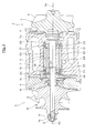
- FIG. 1 shows the main part of a turbocharger incorporating a bearing unit according to the first embodiment of the present invention.
- the turbocharger 1 is used by being attached to an internal combustion engine mounted in a vehicle such as an automobile.
- the turbocharger 1 includes a turbine 2, to which exhaust from the engine is drawn, and a compressor 3, which is driven by the turbine 2 and compresses air to be taken into the engine.
- the turbine 2 has a turbine wheel 5 accommodated in a turbine housing 4.
- the turbine wheel 5 has plural turbine blades 6 arranged in a circumferential direction around the turbine wheel 5.
- a joining means such as welding, the turbine wheel 5 is joined to the right end 7a of a rotary shaft 7 supported so as to freely rotate around an axis Ax.
- a male screw 8 is formed on the left end 7b of the rotary shaft 7.
- the bearing unit 9 supporting the rotary shaft 7 is attached to a bearing housing 10.
- the compressor 3 includes an impeller 12 accommodated in a compressor housing 11.
- the impeller 12 has plural compressor vanes 13 arranged in a circumferential direction around the impeller 12.
- the rotary shaft 7 is inserted into the impeller 12 while a rotation stopper, not shown, is provided.
- Screwed on the left end 7b of the rotary shaft 7 projecting from the impellor 12 is an impeller nut 14 engaging the male screw 8.
- the impeller 12 is fastened by the impeller nut 14 together with the bearing unit 9, and fixed on the rotary shaft 7.
- a retainer 15 and a collar 16 are interposed between the compressor housing 11 and the bearing housing 10.
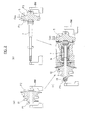
- FIG. 2 is a diagram schematically illustrating the outline of a balance correction process performed during the assembly of the turbocharger 1 shown in FIG. 1 .
- a balance correction process is performed for the turbocharger 1, thereby improving dynamic balance.
- the balance correction process is performed in plural steps during the assembly of the turbocharger 1.
- the impeller 12 is subjected to the balance correction process before assembly.
- the impeller 12 is installed on a given balancing machine BM. While dynamic balance is being measured, parts P1 and P2 to be processed, which are set on the tip corners and rear of the impeller 12, are gradually trimmed. This process is repeated so that the dynamic balance of the impeller 12 falls within a permissible range.
- the rotary shaft 7 with the turbine wheel 5 connected thereto is subjected to a balance correction process, as shown in FIG. 2(b) .
- the rotary shaft 7 in this state is attached to the balancing machine BM.
- parts P3 and P4 to be processed, which are set on the tip corners and rear of the turbine wheel 5, are gradually trimmed until the dynamic balance of the rotary shaft 7 falls within a permissible range.
- blowing a specific inert gas Gas onto the turbine wheel 5 enables the balancing machine BM to measure dynamic balance while rotating the rotary shaft 7.
- the impeller 12 is fastened to the rotary shaft 7 by the impeller nut 14 together with the bearing unit 9 as described above, thereby fitting the components together. Thereafter, a balance correction process is performed as shown in FIG. 2(c) .
- the reason the balance correction process is performed after the components have been fitted together is that while the impeller 12 is being fitted, the impeller nut 14 is screwed tightly on the rotary shaft 7 while movement of the impeller 12 toward the turbine wheel 5 is restricted by the collar 16 and bearing unit 9.
- the rotary shaft 7 is affected by the processing accuracy of each of the components, resulting in its curving in the order of several 10s of micrometers.
- any unbalance caused by such curving is corrected by gradually trimming a part P5 to be processed, which is set on the cephalic portion of the impeller nut 14, while measuring dynamic balance on the balancing machine BM.
- This will be discussed in detail below.
- the characteristic configuration of the bearing unit 9 suppresses curving of the rotary shaft 7 on the turbine wheel 5 side, and any unbalance resulting from the curving of the rotary shaft 7 concentrates on the impeller 12 side. Therefore, performing the correction process for only the impeller 12 side without performing it for the turbine wheel 5 side enables the entire dynamic balance to fall within a permissible range.
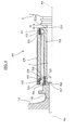
- FIG. 3 is an enlarged diagram of the bearing unit 9 shown in FIG. 1 and the surroundings thereof.
- the bearing unit 9 supports the rotary shaft 7 between the turbine wheel 5 and impeller 12, specifically, between the impeller 12 and a large-diameter turbine-side step 20 formed on the rotary shaft 7, such that the rotary shaft 7 is freely rotatable.
- the bearing unit 9 includes a turbine-side ball bearing 21 in which balls 23 are located on the turbine wheel 5 side; an impeller-side ball bearing 22 in which balls 24 are located on the impeller 12 side and a holder 25 by which these ball bearings 21 and 22 are held by the bearing housing 10.
- Each of the ball bearings 21 and 22 is configured as an angular contact type.
- the turbine-side ball bearing 21 includes an outer race 31 having an outer circumference fitted in the holder 25 and an inner race 32 attached to the rotary shaft 7 and disposed on the inner circumferential side of the outer race 31 so as to be concentric with the outer race 31.
- the outer and inner races 31 and 32 hold the balls 23 such that the balls 23 are able to roll.
- the impeller side ball bearings 22 includes an outer race 33 having an outer circumference fitted in the holder 25 and an inner race 34 attached to the rotary shaft 7 and disposed on the inner circumferential side of the outer race 33 so as to be concentric with the outer race 33.
- the outer and inner races 33 and 34 hold the balls 24 such that the balls 24 are able to roll.
- the inner race 32 of the turbine-side ball bearing 21 extends in one direction toward the impeller 12 side from the position where the balls 23 are held.
- the end of the extending inner race 32 has an inward flange 37, formed as a projecting portion, which juts out toward the center of the rotary shaft 7.
- This inward flange 37 is disposed in contact with a positioning step 38 formed on the rotary shaft 7.
- the positioning step 38 is formed on the rotary shaft 7 so as to increase in diameter toward the turbine wheel 5 side. This positioning step 38 restricts movement of the inner race 32 toward the turbine wheel 5 side, and hence positions the turbine-side ball bearing 21.
- the location where the positioning step 38 is formed and the dimensions of the inner race 32 about the direction of the axis Ax are set such that when movement of the inner race 32 is restricted by the positioning step 38, the end 32a of the turbine wheel 5 side is separated from the turbine-side step 20.
- a gap G is defined between the end 32a and the turbine-side step 20 with no members interposed between them.
- the collar 16 presses the inner race 34. Consequently, the inner race 34 of the impeller-side ball bearing 34 comes into contact with the inner race 32 of the turbine-side ball bearing 21 positioned by the positioning step 38.
- the impeller-side ball bearing 22 is positioned such that the movement of its inner race 34 toward the turbine wheel 5 side is restricted.
- the impeller-side ball bearing 22 is positioned integrally with the turbine-side ball bearing 21. Accordingly, compared to the case where ball bearings 21 and 22 are positioned by separate positioning portions, the number of components and of processing steps can be reduced. Additionally, since a dimensional increase in the direction of the axis Ax can be prevented, space is used more efficiently.
- a bearing unit according to the second embodiment of the present invention will be described with reference to FIG. 4 .
- members in the drawing that are common to the first embodiment are denoted with reference signs identical to those in the drawings used for the first embodiment, and duplicate descriptions are omitted.
- a bearing unit according to the second embodiment can also be incorporated in the turbocharger 1, and the state in which the bearing unit is incorporated in the turbocharger 1 is identical to that in the first embodiment. Therefore, a drawing corresponding to FIG. 1 is omitted.
- FIG. 4 is an enlarged diagram of the bearing unit according to the second embodiment and its surroundings.
- the bearing unit 40 supports a rotary shaft 7 between a turbine-side step 20 and an impeller 12 such that the rotary shaft 7 is freely rotatable.
- the bearing unit 40 includes a turbine-side ball bearing 41 in which balls 43 are located on the turbine wheel 5 side, and an impeller-side ball bearing 42 in which the balls 44 are located on the impeller 12 side.
- the ball bearings 41 and 42 are held by a holder 25.
- Each of the ball bearings 41 and 42 is configured as an angular contact type.
- the turbine-side ball bearing 41 includes an outer race 51, having an outer circumference fitted in the holder 25, and an inner race 52 provided on a rotary shaft 7 and disposed on the inner circumferential side of the outer race 51 so as to be concentric with the outer race 51.
- the outer and inner races 51 and 52 hold the balls 43 such that the balls 43 are able to roll.
- the impeller-side ball bearing 42 includes an outer race 53 having an outer circumference fitted in the holder 25, and an inner race 54 disposed on the inner circumferential side of the outer race 53 so as to be concentric with the outer race 53.
- the outer and inner races 53 and 54 hold the balls 44 such that the balls 44 are able to roll.
- the inner race 52 of the turbine-side ball bearing 41 extends in one direction toward the impeller 12 side from the position where the balls 43 are held.
- a small-diameter portion 55 Formed on the impeller 12 side of the inner race 52 is a small-diameter portion 55 around which the inner race 54 of the impeller-side ball bearing 42 is provided.
- a step 56 is formed on the root of the small-diameter portion 55.
- the leading end of the small-diameter portion 55 has an inward flange 57, formed as a projecting portion, which juts out toward the center of the rotary shaft 7 and comes into contact with a positioning step 58 formed on the rotary shaft 7.
- the positioning step 58 is formed on the rotary shaft 7 so as to increase in diameter toward the turbine wheel 5 side.
- the location where the positioning step 58 is formed is set closer to the impeller 12 than to the position P of the center of each ball 44 of the impeller-side ball bearing 42.
- Movement of the inner race 52 toward the turbine wheel 5 side is restricted by the positioning step 58.
- the turbine-side ball bearing 51 is positioned.
- the location where the positioning step 58 is formed and the dimension of the inner race 52 about the direction of the axis Ax are set such that when movement of the inner race 52 is restricted by the positioning step 58, the end 52a on the turbine wheel 5 side is separated from the turbine-side step 20.
- a gap G is defined between the end 52a and the turbine-side step 20 with no members interposed between them.
- the inner race 54 of the impeller-side ball bearing 42 is provided around the outer circumference of the small-diameter portion 55 formed on the inner race 52 of the turbine-side ball bearing 41.
- a collar 16 presses the inner race 54.
- the inner race 54 comes into contact with a spacer 59 that has been brought into contact with the step 56. Consequently, the impeller-side bearing 42 is positioned by virtue of the movement of the inner race 54 toward the turbine wheel 5 side being restricted.
- the end 52a of the inner race 52 of the turbine-side ball bearing 41 is prevented from coming into contact with the turbine-side step 20 while the impeller 12 is being fitted.
- the location where the positioning step 58 is formed is set closer to the impeller 12 than to the position P of the center of each ball 44 of the impeller-side ball bearing 42. Therefore, curving of the rotary shaft 7 resulting from positioning the turbine-side ball bearing 42 can be further concentrated on the impeller 12 side. This facilitates the balance correction process after the fitting of the impeller 12.
- FIG. 5 a ball bearing unit according to the third embodiment of the present invention will be described with reference to FIG. 5 .
- members in the drawing that are common to the first embodiment are denoted with reference signs identical to those in the drawings used for the first embodiment, and duplicate descriptions are omitted.
- the bearing unit according to the third embodiment can also be incorporated in the turbocharger 1, and the state in which the bearing unit is incorporated in the turbocharger 1 is identical to that in the first embodiment. Therefore, a drawing corresponding to FIG. 1 is omitted.
- FIG. 5 is an enlarged diagram of the bearing unit according to the third embodiment and its surroundings.
- the bearing unit 60 supports a rotary shaft 7 between a turbine-side step 20 and an impeller 12 such that the rotary shaft 7 is freely rotatable.
- the bearing unit 60 includes a turbine-side ball bearing 61 in which balls 63 are located on the turbine wheel 5 side, and an impeller-side ball bearing 62 in which the balls 64 are located on the impeller 12 side.
- the ball bearings 61 and 62 are held by a holder 25.
- Each of the ball bearings 61 and 62 is configured as an angular contact type.
- the turbine-side ball bearing 61 includes an outer race 71 having the outer circumference fitted in the holder 25, and an inner race 72 provided on the rotary shaft 7 and disposed on the inner circumferential side of the outer race 71 so as to be concentric with the outer race 71.
- the outer and inner races 71 and 72 hold the balls 63 such that the balls 63 are able to roll.
- the impeller side ball bearings 62 includes an outer race 73 having the outer circumference fitted in the holder 25, and an inner race 74 provided on the rotary shaft 7 and disposed on the inner circumferential side of the outer race 73 so as to be concentric with the outer race 53.
- the outer race 73 and inner race 74 hold the balls 64 such that the balls 64 are able to roll.
- the inner race 72 of the turbine-side ball bearing 61 extends in one direction toward the impeller 12 side from the position where the balls 63 are held.
- the end of the extending inner race 72 has an inward flange 77, formed as a projecting portion, which juts out toward the center of the rotary shaft 7.
- the inward flange 77 is disposed in contact with a positioning step 78 formed on the rotary shaft 7.
- the third embodiment is different from the first embodiment in the following respects: the inner race 72 of the turbine-side ball bearing 61 is shorter than that in the first embodiment; the location where the positioning step 78 that comes into contact with the inward flange 77 is formed is set near the middle of the rotary shaft 7.
- the positioning step 78 is formed on the rotary shaft 7 so as to increase in diameter toward the turbine wheel 5 side.
- the contact of the inward flange 77 with the positioning step 78 restricts movement of the inner race 72 toward the turbine wheel 5 side.
- the turbine-side ball bearing 61 is positioned.
- the location where the positioning step 78 is formed and the dimension of the inner race 72 about the direction of the axis Ax are set such that when movement of the inner race 72 is restricted by the positioning step 78, the end 72a on the turbine wheel 5 side is separated from the turbine-side step 20.
- a gap G is defined between the end 72a and the turbine-side step 20 with no members interposed between them.
- a spacer 79 with its width in the direction of the axis Ax is interposed between the inner race 74 of the impeller-side ball bearing 62 and the inner race 72 of the turbine-side ball bearing 61. Accordingly, when a collar 16 is pressed against the inner race 74 of the impeller-side ball bearing 62 while the impeller 12 is being fitted, the inner race 74 comes into contact with the spacer 79 and the movement of the inner race 74 is restricted, thereby positioning the impeller-side ball bearing 62. Specifically, with the spacer 79 interposed between the inner races 72 and 74, the impeller-side ball bearing 62, together with the turbine-side ball bearing 61, is positioned by use of the positioning step 78.
- the end 72a of the inner race 72 of the turbine-side ball bearing 41 is prevented from coming into contact with the turbine-side step 20 when the impeller 12 is fitted. Accordingly, curving of the rotary shaft 7 on the turbine side is prevented regardless of the processing accuracy of the inner race 72 and the turbine-side step 20. This eliminates the need to correct any unbalance of the rotary shaft 7 resulting from turbine-side curving.
- the spacer 79 is interposed between the inner races 72 and 74, any dimension error of each of the inner races 72 and 74 in the direction of the axis Ax can be absorbed by correcting the width of the spacer 79. Accordingly, the processing accuracy of each of the inner races 72 and 74, the level of which is stricter due to the sharing of the positioning step 78, can be relaxed by use of the spacer 79. Therefore, processing of the inner races 72 and 74 is facilitated.
- FIG. 6 a ball bearing unit according to the fourth embodiment of the present invention will be described with reference to FIG. 6 .
- members in the drawing that are common to the first embodiment are denoted with reference signs identical to those in the drawings used for the first embodiment, and duplicate descriptions are omitted.
- the bearing unit according to the fourth embodiment can also be incorporated in the turbocharger 1, and the state in which the bearing unit is incorporated in the turbocharger 1 is identical to that in the first embodiment. Therefore, a drawing corresponding to FIG. 1 is omitted.
- FIG. 6 is an enlarged diagram of the bearing unit according to the fourth embodiment and its surroundings.
- the bearing unit 80 supports a rotary shaft 7 between a turbine-side step 20 and an impeller 12 such that the rotary shaft 7 is freely rotatable.
- the bearing unit 80 includes a turbine-side ball bearing 81 in which balls 83 are located on the turbine wheel 5 side, and an impeller-side ball bearing 82 in which the balls 84 are located on the impeller 12 side.
- the ball bearings 81 and 82 are held by a holder 25.
- Each of the ball bearings 81 and 82 is configured as an angular contact type.
- the turbine-side ball bearing 81 includes an outer race 91 having the outer circumference fitted in the holder 25, and an inner race 92 provided on the rotary shaft 7 and disposed on the inner circumferential side of the outer race 91 so as to be concentric with the outer race 91.
- the outer race 91 and inner race 92 hold the balls 83 such that the balls 83 are able to roll.
- the impeller-side ball bearings 82 include an outer race 93 having the outer circumference fitted in the holder 25, and an inner race 94 disposed on the inner circumferential side of the outer race 93 so as to be concentric with the outer race 93.
- the outer race 93 and inner race 94 hold the balls 84 such that the balls 84 are able to roll.
- the inner race 92 of the turbine-side ball bearing 81 extends in one direction toward the impeller 12 side from the position where the balls 83 are held.
- a small-diameter portion 95 Formed in a range from the middle of the inner race 92 to its impeller-side end is a small-diameter portion 95 around which the inner race 94 of the impeller-side ball bearing 82 is provided.
- a step 96 is formed on the root of the small-diameter portion 95.
- the small diameter portion 95 has an inward step 97, formed as a projecting portion, which juts out toward the center of the rotary shaft 7 and comes into contact with a positioning step 98 formed on the rotary shaft 7.
- the positioning step 98 is formed on the rotary shaft 7 so as to increase in diameter toward the turbine wheel 5 side.
- the contact of the inward step 97 with the positioning step 98 restricts movement of the inner race 92 toward the turbine wheel 5 side.
- the turbine-side ball bearing 81 is positioned.
- the location where the positioning step 98 is formed and the dimension of the inner race 92 about the direction of the axis Ax are set such that when movement of the inner race 92 is restricted by the positioning step 98, the end 92a on the turbine wheel 5 side is separated from the turbine-side step 20.
- a gap G is defined between the end 92a and the turbine-side step 20 with no members interposed between them.
- the inner race 94 of the impeller-side ball bearing 82 is provided around the outer circumference of the small-diameter portion 95 formed on the inner race 92 of the turbine-side ball bearing 81. While the impeller 12 is being fitted, a collar 16 presses the inner race 94. Thereby the inner race 94 comes into contact with a spacer 99 that has been brought into contact with the step 96. Consequently, the impeller-side bearing 82 is positioned by virtue of movement of the inner race 94 toward the turbine wheel 5 side being restricted.
- the end 92a of the inner race 92 of the turbine-side ball bearing 81 is prevented from coming into contact with the turbine-side step 20 while the impeller 12 is being fitted. Accordingly, curving of the rotary shaft 7 on the turbine side is prevented regardless of the processing accuracy of the inner race 92 and the turbine-side step 20. This eliminates the need to correct any unbalance of the rotary shaft 7 resulting from turbine-side curving.
- each ball bearing is positioned by a positioning step formed on the rotary shaft.
- each ball bearing may be positioned by providing the rotary shaft with a restricting member, such as a pin, instead of the step, for use as a positioning portion, and restricting movement of the inner race by use of the restricting member.
- each ball bearing may be positioned by tapering the periphery of the rotary shaft around which the inner race is provided, such that the outer diameter of the periphery gradually increases toward the turbine wheel side, thereby forming a positioning portion and restricting movement of the inner race by use of this positioning portion.
- Each of the first and second embodiments has an advantage that the inner race of the turbine-side ball bearing is extended to a point close to the impeller, and movement of the end of the extended inner race is restricted by the positioning portion, thereby concentrating on the impeller side any unbalance caused by curving of the rotary shaft resulting from the positioning of the ball bearings.
- the present invention is not limited to such a form. To be specific, it is enough for the turbine-wheel side end of the inner race to be located away from the turbine-side step, and the present invention can be realized by appropriately setting the dimension about the axial direction of the inner race of the turbine-side ball bearing and the location of the positioning portion within the limit of separation of this end from the turbine-side step. Additionally, the turbine-side and impeller-side ball bearings do not have to be positioned integrally. The present invention may be realized by positioning these by use of separate members.
- the gap is defined between the end of the inner race of the turbine-side ball bearing and the turbine-side step without interposing any member.
- the invention may be realized by filling the gap with a member that ensures a predetermined clearance or other member such as one that more easily deforms elastically than the materials composing the inner race and rotation shaft.
- the form in which such a member is inserted in the gap prevents direct contact of the inner race and the turbine-side step. Accordingly, the purpose of the present invention can be achieved without causing turbine-wheel side curving as a result of positioning of the turbine-side ball bearing.
Landscapes
- Engineering & Computer Science (AREA)
- General Engineering & Computer Science (AREA)
- Mechanical Engineering (AREA)
- Supercharger (AREA)
- Rolling Contact Bearings (AREA)
- Structures Of Non-Positive Displacement Pumps (AREA)
Abstract
Description
- The present invention relates to bearing units for a turbocharger supporting the rotary shaft of the turbocharger by means of a ball bearing such that the rotary shaft is able to rotate.
- Known bearing units for a turbocharger include two ball bearings composed by providing a pair of outer races on both ends of a common inner race, and attaching a spring for applying preload to only the outside of one of the outer races (Patent Literature 1). As other prior art literature related to the present invention,
Patent Literatures 2 to 4 have been proposed. -
- Patent Literature 1:
JP-A-2005-172099 - Patent Literature 2:
JP-A-2008-88855 - Patent Literature 3:
JP-A-2008-298284 - Patent Literature 4:
JP-A-2007-71356 - A bearing unit in the Patent Literature 1 is configured as described below. While the bearing unit is being fitted to a turbocharger, the turbine-side end of an inner race is brought into contact with a step formed on the rotary shaft. Additionally, while the impeller-side end is kept in contact with a spacer provided around the periphery of the rotary shaft, the spacer is compressed, thereby positioning each ball bearing. Therefore, while the bearing unit is being fitted to the turbocharger, the inner race is compressed as it is kept in contact with the step of the rotary shaft. As a result, the rotary shaft may curve on the turbine side due to the processing accuracy, such as angularity, of the step and inner race. Consequently, a curve that has been caused on the turbine side of rotary shaft may result in unbalance of the rotary shaft. This unbalance has to be corrected.
- Accordingly, it is an object of the present invention to provide bearing units for a turbocharger, which prevent turbine-side curving of a rotary shaft while the bearing units are being fitted to the turbocharger.
- A bearing unit for a turbocharger according to the present invention supports a rotary shaft having one end provided with a turbine, the other end provided with an impeller, and a large-diameter turbine-side step formed on the turbine wheel side, the rotary shaft being supported between the turbine-side step and the impeller such that the rotary shaft is freely rotatable. This bearing unit comprises: a turbine-side ball bearing in which balls are located on the turbine-wheel side; an impeller-side ball bearing positioned such that balls are located on the impeller side; and a positioning portion configured to restrict movement of an inner race of the turbine-side ball bearing toward the turbine wheel side and to position the turbine-side ball bearing such that the turbine wheel side end of the inner race is separated from the turbine side step.
- In this bearing unit, the turbine-side ball bearing is positioned by the positioning portion such that the turbine-wheel side end of the inner race is separated from the turbine-side step. Accordingly, while the bearing unit is being fitted to the turbocharger, contact of the inner race of the turbine-side ball bearing with the turbine-side step can be avoided. Accordingly, regardless of the processing accuracy of the inner race and turbine-side step, turbine-side curving of the rotation shaft can be prevented. This eliminates the need to correct unbalance of the rotary shaft otherwise resulting from turbine-side curving.
- In one aspect of the bearing system according to the present invention, the inner race of the turbine-side ball bearing extends to a point close to the impeller, and movement of the impeller-side end of this inner race may be restricted by the positioning portion. Generally, unbalance of the rotary shaft is corrected by trimming predetermined parts of rotating elements, such as the impeller and rotary shaft. After correction of such unbalance, fitting of the bearing system to the turbocharger is completed. According to this aspect, the turbine-side ball bearing is positioned close to the impeller; therefore, curving of the rotary shaft, which may be caused while the bearing unit is being fitted to the turbocharger, concentrates on the impeller side. Accordingly, performing a process only for the impeller side makes it possible to correct unbalance of the rotary shaft that may result from curving of the rotary shaft due to positioning of the impeller-side ball bearing or curving of the rotary shaft due to positioning of the turbine-side ball bearing. Since a process for correcting such unbalance does not have to be performed for the turbine side, the time and effort required for a balance correction process can be eliminated.
- In this aspect, while movement of the inner race of the impeller-side ball bearing toward the turbine wheel side is restricted, the inner race of the impeller-side ball bearing may be fitted around an outer circumference of the inner race of the turbine-side ball bearing, and the positioning portion may be located closer to the impeller than to the center of any of the balls of the impeller-side ball bearing. In this case, the turbine-side ball bearing can be positioned closer to the impeller than to the center of any of the balls of the impeller-side ball bearing. Accordingly, any curving of the rotary shaft resulting from the positioning of the turbine-side ball bearing can be further concentrated on the impeller side.
- In another aspect of the bearing unit of the present invention, the impeller-side ball bearing may be positioned integrally with the turbine-side ball bearing by use of the positioning portion. According to this aspect, the impeller-side ball bearing can be positioned using the positioning portion provided to position the turbine-side ball bearing. Accordingly, compared to the case where the ball bearings are positioned by separate positioning portions, the number of components and the man-hours required for processing can be decreased and a dimensional increase in the direction of the axis can be prevented, resulting in a more efficient use of space.
- In this aspect, the bearing system may further include a spacer interposed between the respective inner races of the impeller-side ball bearing and turbine-side ball bearing and having its width about the direction of an axis of the rotary shaft. In this case, correcting the width of the spacer interposed between the inner races in the axial direction can absorb dimension errors of the inner races of the impeller-side ball bearing and turbine-side ball bearing in the axial direction. Accordingly, the processing accuracy of an inner race of stricter level due to the sharing of the positioning step can be relaxed by use of the spacer. Thus processing of the inner races is facilitated.
- In the bearing unit according to the present invention, the configuration of the positioning portion may be realized in various aspects. For example, the rotary shaft may be provided with a restricting member, such as a pin, for use as a positioning portion, and thus movement of each inner race may be restricted. Alternatively, movement of each inner race may be restricted by tapering the periphery of the rotary shaft around which the inner race is provided such that the outer diameter of the periphery gradually increases toward the turbine wheel. Additionally, as an aspect different from the foregoing aspects, the inner race of the turbine-side ball bearing may have a projecting portion which juts out toward the center of the rotation shaft, and the positioning portion may be provided as a positioning step formed on the rotary shaft so as to increase in diameter toward the turbine wheel side and be able to come into contact with the projecting portion. In this case, it is unnecessary to provide an additional member in order to realize the positioning portion, and processing is also easier.
-
-
FIG. 1 is a diagram showing the main part of a turbocharger incorporating a bearing unit according to the first embodiment of the present invention. -
FIG. 2 is a diagram schematically illustrating the outline of a balance correction process performed during the assembly of the turbocharger shown inFIG. 1 . -
FIG. 3 is an enlarged diagram of the bearing unit shown inFIG. 1 and the surroundings thereof. -
FIG. 4 is an enlarged diagram of the bearing unit according to the second embodiment and its surroundings. -
FIG. 5 is an enlarged diagram of the bearing unit according to the third embodiment and its surroundings. -
FIG. 6 is an enlarged diagram of the bearing unit according to the fourth embodiment and its surroundings. -
FIG. 1 shows the main part of a turbocharger incorporating a bearing unit according to the first embodiment of the present invention. The turbocharger 1 is used by being attached to an internal combustion engine mounted in a vehicle such as an automobile. The turbocharger 1 includes aturbine 2, to which exhaust from the engine is drawn, and acompressor 3, which is driven by theturbine 2 and compresses air to be taken into the engine. Theturbine 2 has aturbine wheel 5 accommodated in aturbine housing 4. Theturbine wheel 5 hasplural turbine blades 6 arranged in a circumferential direction around theturbine wheel 5. Using a joining means such as welding, theturbine wheel 5 is joined to theright end 7a of arotary shaft 7 supported so as to freely rotate around an axis Ax. A male screw 8 is formed on theleft end 7b of therotary shaft 7. Thebearing unit 9 supporting therotary shaft 7 is attached to a bearinghousing 10. - The
compressor 3 includes animpeller 12 accommodated in acompressor housing 11. Theimpeller 12 hasplural compressor vanes 13 arranged in a circumferential direction around theimpeller 12. Therotary shaft 7 is inserted into theimpeller 12 while a rotation stopper, not shown, is provided. Screwed on theleft end 7b of therotary shaft 7 projecting from theimpellor 12 is animpeller nut 14 engaging the male screw 8. Thus, theimpeller 12 is fastened by theimpeller nut 14 together with thebearing unit 9, and fixed on therotary shaft 7. In order to restrict movement of thebearing unit 9 in the direction of the axis Ax, aretainer 15 and acollar 16 are interposed between thecompressor housing 11 and the bearinghousing 10. -
FIG. 2 is a diagram schematically illustrating the outline of a balance correction process performed during the assembly of the turbocharger 1 shown inFIG. 1 . In order to suppress occurrence of vibration and noise during high-speed rotation, a balance correction process is performed for the turbocharger 1, thereby improving dynamic balance. The balance correction process is performed in plural steps during the assembly of the turbocharger 1. First, as shown inFIG. 2(a) , theimpeller 12 is subjected to the balance correction process before assembly. Theimpeller 12 is installed on a given balancing machine BM. While dynamic balance is being measured, parts P1 and P2 to be processed, which are set on the tip corners and rear of theimpeller 12, are gradually trimmed. This process is repeated so that the dynamic balance of theimpeller 12 falls within a permissible range. - On the other hand, subsequent to or parallel to this process shown in
FIG. 2(a) , therotary shaft 7 with theturbine wheel 5 connected thereto is subjected to a balance correction process, as shown inFIG. 2(b) . Therotary shaft 7 in this state is attached to the balancing machine BM. Then, in the same manner as that inFIG. 2(a) , while dynamic balance is being measured, parts P3 and P4 to be processed, which are set on the tip corners and rear of theturbine wheel 5, are gradually trimmed until the dynamic balance of therotary shaft 7 falls within a permissible range. Incidentally, blowing a specific inert gas Gas onto theturbine wheel 5 enables the balancing machine BM to measure dynamic balance while rotating therotary shaft 7. - After the balance correction processes are performed in the steps shown in
FIGS. 2(a) and (b) , theimpeller 12 is fastened to therotary shaft 7 by theimpeller nut 14 together with thebearing unit 9 as described above, thereby fitting the components together. Thereafter, a balance correction process is performed as shown inFIG. 2(c) . The reason the balance correction process is performed after the components have been fitted together is that while theimpeller 12 is being fitted, theimpeller nut 14 is screwed tightly on therotary shaft 7 while movement of theimpeller 12 toward theturbine wheel 5 is restricted by thecollar 16 andbearing unit 9. As a result, therotary shaft 7 is affected by the processing accuracy of each of the components, resulting in its curving in the order of several 10s of micrometers. Any unbalance caused by such curving is corrected by gradually trimming a part P5 to be processed, which is set on the cephalic portion of theimpeller nut 14, while measuring dynamic balance on the balancing machine BM. This will be discussed in detail below. However, while theimpeller 12 is being fitted, the characteristic configuration of thebearing unit 9 suppresses curving of therotary shaft 7 on theturbine wheel 5 side, and any unbalance resulting from the curving of therotary shaft 7 concentrates on theimpeller 12 side. Therefore, performing the correction process for only theimpeller 12 side without performing it for theturbine wheel 5 side enables the entire dynamic balance to fall within a permissible range. -
FIG. 3 is an enlarged diagram of thebearing unit 9 shown inFIG. 1 and the surroundings thereof. As shown inFIG. 3 , thebearing unit 9 supports therotary shaft 7 between theturbine wheel 5 andimpeller 12, specifically, between theimpeller 12 and a large-diameter turbine-side step 20 formed on therotary shaft 7, such that therotary shaft 7 is freely rotatable. Thebearing unit 9 includes a turbine-side ball bearing 21 in whichballs 23 are located on theturbine wheel 5 side; an impeller-side ball bearing 22 in whichballs 24 are located on theimpeller 12 side and aholder 25 by which theseball bearings housing 10. Each of theball bearings holder 25 through an oil passage 28 (FIG. 1 ) formed in the bearinghousing 10, and the oil is supplied to each of theball bearings side ball bearing 21 includes anouter race 31 having an outer circumference fitted in theholder 25 and aninner race 32 attached to therotary shaft 7 and disposed on the inner circumferential side of theouter race 31 so as to be concentric with theouter race 31. The outer andinner races balls 23 such that theballs 23 are able to roll. The impellerside ball bearings 22 includes anouter race 33 having an outer circumference fitted in theholder 25 and aninner race 34 attached to therotary shaft 7 and disposed on the inner circumferential side of theouter race 33 so as to be concentric with theouter race 33. The outer andinner races balls 24 such that theballs 24 are able to roll. - The
inner race 32 of the turbine-side ball bearing 21 extends in one direction toward theimpeller 12 side from the position where theballs 23 are held. The end of the extendinginner race 32 has aninward flange 37, formed as a projecting portion, which juts out toward the center of therotary shaft 7. Thisinward flange 37 is disposed in contact with apositioning step 38 formed on therotary shaft 7. Thepositioning step 38 is formed on therotary shaft 7 so as to increase in diameter toward theturbine wheel 5 side. Thispositioning step 38 restricts movement of theinner race 32 toward theturbine wheel 5 side, and hence positions the turbine-side ball bearing 21. The location where thepositioning step 38 is formed and the dimensions of theinner race 32 about the direction of the axis Ax are set such that when movement of theinner race 32 is restricted by thepositioning step 38, theend 32a of theturbine wheel 5 side is separated from the turbine-side step 20. In this embodiment, a gap G is defined between theend 32a and the turbine-side step 20 with no members interposed between them. - While the
impeller 12 is being fitted, thecollar 16 presses theinner race 34. Consequently, theinner race 34 of the impeller-side ball bearing 34 comes into contact with theinner race 32 of the turbine-side ball bearing 21 positioned by thepositioning step 38. Thus, the impeller-side ball bearing 22 is positioned such that the movement of itsinner race 34 toward theturbine wheel 5 side is restricted. In other words, using thepositioning step 38, the impeller-side ball bearing 22 is positioned integrally with the turbine-side ball bearing 21. Accordingly, compared to the case whereball bearings - In the
inner race 32 of the turbine-side ball bearing 21, theend 32a on theturbine wheel 5 side does not come into contact with the turbine-side step 20 while theimpeller 12 is being fitted. Accordingly, curving of therotary shaft 7 on theturbine wheel 5 side is prevented. That is, curving of therotary shaft 7, which is caused during the fitting of theimpeller 12, concentrates on theimpeller 12 side. Therefore, as shown inFIG.2(c) , performing the balance correction process only for the part P5 to be processed, which is set on theimpeller side 12, makes it possible to correct any unbalance resulting from curving of therotary shaft 7 with fitting thebearing unit 9, that is, with positioning theball bearings - Next, a bearing unit according to the second embodiment of the present invention will be described with reference to
FIG. 4 . In the description below, members in the drawing that are common to the first embodiment are denoted with reference signs identical to those in the drawings used for the first embodiment, and duplicate descriptions are omitted. Additionally, as in the first embodiment, a bearing unit according to the second embodiment can also be incorporated in the turbocharger 1, and the state in which the bearing unit is incorporated in the turbocharger 1 is identical to that in the first embodiment. Therefore, a drawing corresponding toFIG. 1 is omitted. -
FIG. 4 is an enlarged diagram of the bearing unit according to the second embodiment and its surroundings. As shown inFIG. 4 , the bearingunit 40 supports arotary shaft 7 between a turbine-side step 20 and animpeller 12 such that therotary shaft 7 is freely rotatable. The bearingunit 40 includes a turbine-side ball bearing 41 in whichballs 43 are located on theturbine wheel 5 side, and an impeller-side ball bearing 42 in which theballs 44 are located on theimpeller 12 side. Theball bearings holder 25. Each of theball bearings - The turbine-
side ball bearing 41 includes anouter race 51, having an outer circumference fitted in theholder 25, and aninner race 52 provided on arotary shaft 7 and disposed on the inner circumferential side of theouter race 51 so as to be concentric with theouter race 51. The outer andinner races balls 43 such that theballs 43 are able to roll. The impeller-side ball bearing 42 includes anouter race 53 having an outer circumference fitted in theholder 25, and aninner race 54 disposed on the inner circumferential side of theouter race 53 so as to be concentric with theouter race 53. The outer andinner races balls 44 such that theballs 44 are able to roll. Theinner race 52 of the turbine-side ball bearing 41 extends in one direction toward theimpeller 12 side from the position where theballs 43 are held. Formed on theimpeller 12 side of theinner race 52 is a small-diameter portion 55 around which theinner race 54 of the impeller-side ball bearing 42 is provided. Astep 56 is formed on the root of the small-diameter portion 55. The leading end of the small-diameter portion 55 has aninward flange 57, formed as a projecting portion, which juts out toward the center of therotary shaft 7 and comes into contact with apositioning step 58 formed on therotary shaft 7. Thepositioning step 58 is formed on therotary shaft 7 so as to increase in diameter toward theturbine wheel 5 side. The location where thepositioning step 58 is formed is set closer to theimpeller 12 than to the position P of the center of eachball 44 of the impeller-side ball bearing 42. - Movement of the
inner race 52 toward theturbine wheel 5 side is restricted by thepositioning step 58. Thereby the turbine-side ball bearing 51 is positioned. The location where thepositioning step 58 is formed and the dimension of theinner race 52 about the direction of the axis Ax are set such that when movement of theinner race 52 is restricted by thepositioning step 58, theend 52a on theturbine wheel 5 side is separated from the turbine-side step 20. As in the first embodiment, in this embodiment also, a gap G is defined between theend 52a and the turbine-side step 20 with no members interposed between them. - The
inner race 54 of the impeller-side ball bearing 42 is provided around the outer circumference of the small-diameter portion 55 formed on theinner race 52 of the turbine-side ball bearing 41. When theimpeller 12 is fitted, acollar 16 presses theinner race 54. Thereby theinner race 54 comes into contact with aspacer 59 that has been brought into contact with thestep 56. Consequently, the impeller-side bearing 42 is positioned by virtue of the movement of theinner race 54 toward theturbine wheel 5 side being restricted. - According to the second embodiment, the
end 52a of theinner race 52 of the turbine-side ball bearing 41 is prevented from coming into contact with the turbine-side step 20 while theimpeller 12 is being fitted. Thus, the same effect is yielded as in the first embodiment. Furthermore, in the second embodiment, the location where thepositioning step 58 is formed is set closer to theimpeller 12 than to the position P of the center of eachball 44 of the impeller-side ball bearing 42. Therefore, curving of therotary shaft 7 resulting from positioning the turbine-side ball bearing 42 can be further concentrated on theimpeller 12 side. This facilitates the balance correction process after the fitting of theimpeller 12. - Next, a ball bearing unit according to the third embodiment of the present invention will be described with reference to
FIG. 5 . In the description below, members in the drawing that are common to the first embodiment are denoted with reference signs identical to those in the drawings used for the first embodiment, and duplicate descriptions are omitted. Additionally, as in the first embodiment, the bearing unit according to the third embodiment can also be incorporated in the turbocharger 1, and the state in which the bearing unit is incorporated in the turbocharger 1 is identical to that in the first embodiment. Therefore, a drawing corresponding toFIG. 1 is omitted. -
FIG. 5 is an enlarged diagram of the bearing unit according to the third embodiment and its surroundings. As shown inFIG. 5 , the bearingunit 60 supports arotary shaft 7 between a turbine-side step 20 and animpeller 12 such that therotary shaft 7 is freely rotatable. The bearingunit 60 includes a turbine-side ball bearing 61 in whichballs 63 are located on theturbine wheel 5 side, and an impeller-side ball bearing 62 in which theballs 64 are located on theimpeller 12 side. Theball bearings holder 25. Each of theball bearings side ball bearing 61 includes anouter race 71 having the outer circumference fitted in theholder 25, and aninner race 72 provided on therotary shaft 7 and disposed on the inner circumferential side of theouter race 71 so as to be concentric with theouter race 71. The outer andinner races balls 63 such that theballs 63 are able to roll. The impellerside ball bearings 62 includes anouter race 73 having the outer circumference fitted in theholder 25, and aninner race 74 provided on therotary shaft 7 and disposed on the inner circumferential side of theouter race 73 so as to be concentric with theouter race 53. Theouter race 73 andinner race 74 hold theballs 64 such that theballs 64 are able to roll. - The
inner race 72 of the turbine-side ball bearing 61 extends in one direction toward theimpeller 12 side from the position where theballs 63 are held. The end of the extendinginner race 72 has aninward flange 77, formed as a projecting portion, which juts out toward the center of therotary shaft 7. Theinward flange 77 is disposed in contact with apositioning step 78 formed on therotary shaft 7. The third embodiment is different from the first embodiment in the following respects: theinner race 72 of the turbine-side ball bearing 61 is shorter than that in the first embodiment; the location where thepositioning step 78 that comes into contact with theinward flange 77 is formed is set near the middle of therotary shaft 7.
Thepositioning step 78 is formed on therotary shaft 7 so as to increase in diameter toward theturbine wheel 5 side. The contact of theinward flange 77 with thepositioning step 78 restricts movement of theinner race 72 toward theturbine wheel 5 side. Thereby, the turbine-side ball bearing 61 is positioned. The location where thepositioning step 78 is formed and the dimension of theinner race 72 about the direction of the axis Ax are set such that when movement of theinner race 72 is restricted by thepositioning step 78, theend 72a on theturbine wheel 5 side is separated from the turbine-side step 20.
As in the embodiments described above, in this embodiment also, a gap G is defined between theend 72a and the turbine-side step 20 with no members interposed between them. - A
spacer 79 with its width in the direction of the axis Ax is interposed between theinner race 74 of the impeller-side ball bearing 62 and theinner race 72 of the turbine-side ball bearing 61. Accordingly, when acollar 16 is pressed against theinner race 74 of the impeller-side ball bearing 62 while theimpeller 12 is being fitted, theinner race 74 comes into contact with thespacer 79 and the movement of theinner race 74 is restricted, thereby positioning the impeller-side ball bearing 62. Specifically, with thespacer 79 interposed between theinner races side ball bearing 62, together with the turbine-side ball bearing 61, is positioned by use of thepositioning step 78. - According to the third embodiment, the
end 72a of theinner race 72 of the turbine-side ball bearing 41 is prevented from coming into contact with the turbine-side step 20 when theimpeller 12 is fitted. Accordingly, curving of therotary shaft 7 on the turbine side is prevented regardless of the processing accuracy of theinner race 72 and the turbine-side step 20. This eliminates the need to correct any unbalance of therotary shaft 7 resulting from turbine-side curving. Further, in the third embodiment, since thespacer 79 is interposed between theinner races inner races spacer 79. Accordingly, the processing accuracy of each of theinner races positioning step 78, can be relaxed by use of thespacer 79. Therefore, processing of theinner races - Next, a ball bearing unit according to the fourth embodiment of the present invention will be described with reference to
FIG. 6 . In the description below, members in the drawing that are common to the first embodiment are denoted with reference signs identical to those in the drawings used for the first embodiment, and duplicate descriptions are omitted. Additionally, as in the first embodiment, the bearing unit according to the fourth embodiment can also be incorporated in the turbocharger 1, and the state in which the bearing unit is incorporated in the turbocharger 1 is identical to that in the first embodiment. Therefore, a drawing corresponding toFIG. 1 is omitted. -
FIG. 6 is an enlarged diagram of the bearing unit according to the fourth embodiment and its surroundings. As shown inFIG. 6 , the bearingunit 80 supports arotary shaft 7 between a turbine-side step 20 and animpeller 12 such that therotary shaft 7 is freely rotatable. The bearingunit 80 includes a turbine-side ball bearing 81 in whichballs 83 are located on theturbine wheel 5 side, and an impeller-side ball bearing 82 in which theballs 84 are located on theimpeller 12 side. Theball bearings holder 25. Each of theball bearings - The turbine-
side ball bearing 81 includes anouter race 91 having the outer circumference fitted in theholder 25, and aninner race 92 provided on therotary shaft 7 and disposed on the inner circumferential side of theouter race 91 so as to be concentric with theouter race 91. Theouter race 91 andinner race 92 hold theballs 83 such that theballs 83 are able to roll. The impeller-side ball bearings 82 include anouter race 93 having the outer circumference fitted in theholder 25, and aninner race 94 disposed on the inner circumferential side of theouter race 93 so as to be concentric with theouter race 93. Theouter race 93 andinner race 94 hold theballs 84 such that theballs 84 are able to roll. Theinner race 92 of the turbine-side ball bearing 81 extends in one direction toward theimpeller 12 side from the position where theballs 83 are held. Formed in a range from the middle of theinner race 92 to its impeller-side end is a small-diameter portion 95 around which theinner race 94 of the impeller-side ball bearing 82 is provided. Astep 96 is formed on the root of the small-diameter portion 95. Thesmall diameter portion 95 has aninward step 97, formed as a projecting portion, which juts out toward the center of therotary shaft 7 and comes into contact with apositioning step 98 formed on therotary shaft 7. Thepositioning step 98 is formed on therotary shaft 7 so as to increase in diameter toward theturbine wheel 5 side. - The contact of the
inward step 97 with thepositioning step 98 restricts movement of theinner race 92 toward theturbine wheel 5 side. Thereby, the turbine-side ball bearing 81 is positioned. The location where thepositioning step 98 is formed and the dimension of theinner race 92 about the direction of the axis Ax are set such that when movement of theinner race 92 is restricted by thepositioning step 98, theend 92a on theturbine wheel 5 side is separated from the turbine-side step 20.
As in the first embodiment, in this embodiment also, a gap G is defined between theend 92a and the turbine-side step 20 with no members interposed between them. - The
inner race 94 of the impeller-side ball bearing 82 is provided around the outer circumference of the small-diameter portion 95 formed on theinner race 92 of the turbine-side ball bearing 81. While theimpeller 12 is being fitted, acollar 16 presses theinner race 94. Thereby theinner race 94 comes into contact with aspacer 99 that has been brought into contact with thestep 96. Consequently, the impeller-side bearing 82 is positioned by virtue of movement of theinner race 94 toward theturbine wheel 5 side being restricted. - According to the fourth embodiment, the
end 92a of theinner race 92 of the turbine-side ball bearing 81 is prevented from coming into contact with the turbine-side step 20 while theimpeller 12 is being fitted. Accordingly, curving of therotary shaft 7 on the turbine side is prevented regardless of the processing accuracy of theinner race 92 and the turbine-side step 20. This eliminates the need to correct any unbalance of therotary shaft 7 resulting from turbine-side curving. - It is understood that the present invention is not limited to each embodiment described above but may be realized in various forms within the scope of the invention. In each embodiment, each ball bearing is positioned by a positioning step formed on the rotary shaft. However, each ball bearing may be positioned by providing the rotary shaft with a restricting member, such as a pin, instead of the step, for use as a positioning portion, and restricting movement of the inner race by use of the restricting member. Alternatively, each ball bearing may be positioned by tapering the periphery of the rotary shaft around which the inner race is provided, such that the outer diameter of the periphery gradually increases toward the turbine wheel side, thereby forming a positioning portion and restricting movement of the inner race by use of this positioning portion.
- Each of the first and second embodiments has an advantage that the inner race of the turbine-side ball bearing is extended to a point close to the impeller, and movement of the end of the extended inner race is restricted by the positioning portion, thereby concentrating on the impeller side any unbalance caused by curving of the rotary shaft resulting from the positioning of the ball bearings. However, the present invention is not limited to such a form. To be specific, it is enough for the turbine-wheel side end of the inner race to be located away from the turbine-side step, and the present invention can be realized by appropriately setting the dimension about the axial direction of the inner race of the turbine-side ball bearing and the location of the positioning portion within the limit of separation of this end from the turbine-side step. Additionally, the turbine-side and impeller-side ball bearings do not have to be positioned integrally. The present invention may be realized by positioning these by use of separate members.
- In each embodiment described above, the gap is defined between the end of the inner race of the turbine-side ball bearing and the turbine-side step without interposing any member. However, the invention may be realized by filling the gap with a member that ensures a predetermined clearance or other member such as one that more easily deforms elastically than the materials composing the inner race and rotation shaft. The form in which such a member is inserted in the gap prevents direct contact of the inner race and the turbine-side step. Accordingly, the purpose of the present invention can be achieved without causing turbine-wheel side curving as a result of positioning of the turbine-side ball bearing.
Claims (6)
- A bearing unit for a turbocharger supporting a rotary shaft having one end provided with a turbine wheel, the other end provided with an impeller, and a large-diameter turbine-side step formed on the turbine wheel side, the rotary shaft being supported between the turbine-side step and the impeller such that the rotary shaft is freely rotatable, the bearing unit comprises:a turbine-side ball bearing in which balls are located on the turbine-wheel side;an impeller-side ball bearing positioned such that balls are located on the impeller side; anda positioning portion configured to restrict movement of an inner race of the turbine-side ball bearing toward the turbine wheel side and to position the turbine-side ball bearing such that the turbine wheel side end of the inner race is separated from the turbine side step.
- The bearing unit according to claim 1, wherein the inner race of the turbine-side ball bearing extends to a point close to the impeller, wherein movement of the impeller-side end of the inner race is restricted by the positioning portion.
- The bearing system according to claim 2, wherein while movement of the inner race of the impeller-side ball bearing toward the turbine wheel side is restricted, the inner race of the impeller-side ball bearing is provided around an outer circumference of the inner race of the turbine-side ball bearing, wherein the positioning portion is located closer to the impeller than to the center of any of the balls of the impeller-side ball bearing.
- The bearing unit according to claim 1 or 2, wherein the impeller-side ball bearing is positioned integrally with the turbine-side ball bearing by use of the positioning portion.
- The bearing unit according to claim 4, further comprising a spacer interposed between the respective inner races of the impeller-side ball bearing and turbine-side ball bearing and having its width about the direction of an axis of the rotary shaft.
- The bearing unit according to any one of claims 1 to 5, wherein the inner race of the turbine-side ball bearing has a projecting portion, which juts out toward the center of the rotation shaft, and wherein the positioning portion is provided in the form of a positioning step, wherein the positioning step is formed on the rotary shaft so as to increase in diameter toward the turbine wheel side and able to come into contact with the projecting portion.
Applications Claiming Priority (1)
| Application Number | Priority Date | Filing Date | Title |
|---|---|---|---|
| PCT/JP2009/056305 WO2010109653A1 (en) | 2009-03-27 | 2009-03-27 | Bearing unit for turbocharger |
Publications (3)
| Publication Number | Publication Date |
|---|---|
| EP2420660A1 true EP2420660A1 (en) | 2012-02-22 |
| EP2420660A4 EP2420660A4 (en) | 2013-08-21 |
| EP2420660B1 EP2420660B1 (en) | 2015-03-04 |
Family
ID=42780362
Family Applications (1)
| Application Number | Title | Priority Date | Filing Date |
|---|---|---|---|
| EP09842267.8A Not-in-force EP2420660B1 (en) | 2009-03-27 | 2009-03-27 | Bearing unit for turbocharger |
Country Status (5)
| Country | Link |
|---|---|
| US (1) | US8602655B2 (en) |
| EP (1) | EP2420660B1 (en) |
| JP (1) | JP5120494B2 (en) |
| CN (1) | CN102365440B (en) |
| WO (1) | WO2010109653A1 (en) |
Cited By (13)
| Publication number | Priority date | Publication date | Assignee | Title |
|---|---|---|---|---|
| WO2015058779A1 (en) * | 2013-10-24 | 2015-04-30 | Volvo Truck Corporation | A turbocompound unit |
| US9638138B2 (en) | 2015-03-09 | 2017-05-02 | Caterpillar Inc. | Turbocharger and method |
| US9650913B2 (en) | 2015-03-09 | 2017-05-16 | Caterpillar Inc. | Turbocharger turbine containment structure |
| US9683520B2 (en) | 2015-03-09 | 2017-06-20 | Caterpillar Inc. | Turbocharger and method |
| US9732633B2 (en) | 2015-03-09 | 2017-08-15 | Caterpillar Inc. | Turbocharger turbine assembly |
| US9739238B2 (en) | 2015-03-09 | 2017-08-22 | Caterpillar Inc. | Turbocharger and method |
| US9752536B2 (en) | 2015-03-09 | 2017-09-05 | Caterpillar Inc. | Turbocharger and method |
| US9822700B2 (en) | 2015-03-09 | 2017-11-21 | Caterpillar Inc. | Turbocharger with oil containment arrangement |
| US9879594B2 (en) | 2015-03-09 | 2018-01-30 | Caterpillar Inc. | Turbocharger turbine nozzle and containment structure |
| US9890788B2 (en) | 2015-03-09 | 2018-02-13 | Caterpillar Inc. | Turbocharger and method |
| US9903225B2 (en) | 2015-03-09 | 2018-02-27 | Caterpillar Inc. | Turbocharger with low carbon steel shaft |
| US9915172B2 (en) | 2015-03-09 | 2018-03-13 | Caterpillar Inc. | Turbocharger with bearing piloted compressor wheel |
| FR3073558A1 (en) * | 2017-11-10 | 2019-05-17 | Safran Aircraft Engines | BEARING BLOCK EQUIPPED FOR TURBOMACHINE |
Families Citing this family (20)
| Publication number | Priority date | Publication date | Assignee | Title |
|---|---|---|---|---|
| WO2014004245A1 (en) * | 2012-06-25 | 2014-01-03 | Borgwarner Inc. | Exhaust-gas turbocharger |
| JP6189021B2 (en) | 2012-07-17 | 2017-08-30 | 株式会社浅野歯車工作所 | Impeller rotating body and rotating body |
| CN103233210B (en) * | 2013-05-20 | 2015-06-03 | 吉林大学 | Organic metal chemical vapor deposition equipment for high-temperature growth of oxide film |
| DE102013210990A1 (en) * | 2013-06-13 | 2014-12-18 | Continental Automotive Gmbh | Exhaust gas turbocharger with a radial-axial turbine wheel |
| JP6250360B2 (en) * | 2013-10-22 | 2017-12-20 | Ntn株式会社 | Turbocharger bearing device and method of manufacturing turbocharger bearing device |
| US9664050B2 (en) * | 2013-10-25 | 2017-05-30 | Ecomotors, Inc. | Bearings for a turbomachine having an electric motor |
| CN105332115B (en) * | 2014-05-30 | 2020-07-31 | 舍弗勒技术股份两合公司 | Bearing assembly |
| DE102015106638A1 (en) * | 2014-07-02 | 2016-01-07 | Pierburg Gmbh | Fastening device and method for mounting an impeller of a compressor on a drive shaft |
| JP6582389B2 (en) * | 2014-10-24 | 2019-10-02 | トヨタ自動車株式会社 | Supercharger bearing structure |
| US9810238B2 (en) | 2015-03-09 | 2017-11-07 | Caterpillar Inc. | Turbocharger with turbine shroud |
| US10066639B2 (en) | 2015-03-09 | 2018-09-04 | Caterpillar Inc. | Compressor assembly having a vaneless space |
| US9777747B2 (en) | 2015-03-09 | 2017-10-03 | Caterpillar Inc. | Turbocharger with dual-use mounting holes |
| US10006341B2 (en) | 2015-03-09 | 2018-06-26 | Caterpillar Inc. | Compressor assembly having a diffuser ring with tabs |
| JP6540281B2 (en) * | 2015-06-30 | 2019-07-10 | 日本精工株式会社 | Double row ball bearing |
| JP6723103B2 (en) * | 2016-07-21 | 2020-07-15 | 日鍛バルブ株式会社 | Shaft manufacturing method |
| CN107120184B (en) * | 2017-06-23 | 2023-06-23 | 黄石炫轺者动力科技有限公司 | Suspension shaft centrifugal supercharger with axial limiting characteristic |
| DE102018202301A1 (en) * | 2018-02-15 | 2019-08-22 | Minebea Mitsumi Inc. | Bearing unit for a turbocharger or an exhaust gas turbine, and turbocharger and exhaust gas turbine with such a storage unit |
| JP7393095B2 (en) * | 2018-06-07 | 2023-12-06 | トヨタ自動車株式会社 | gas compression equipment |
| DE112019007710B4 (en) * | 2019-11-12 | 2025-10-09 | Mitsubishi Heavy Industries Engine & Turbocharger, Ltd. | Rotor balance adjustment procedure |
| US11549555B1 (en) * | 2021-06-29 | 2023-01-10 | Garrett Transportation I Inc. | Turbomachine with roller element bearing arrangement |
Family Cites Families (35)
| Publication number | Priority date | Publication date | Assignee | Title |
|---|---|---|---|---|
| US2973136A (en) * | 1957-06-13 | 1961-02-28 | Garrett Corp | Compressor |
| JPS6117561U (en) * | 1984-07-06 | 1986-02-01 | トヨタ自動車株式会社 | Lubrication mechanism of automotive final reducer |
| DE3531313C3 (en) * | 1984-09-03 | 1995-04-20 | Ishikawajima Harima Heavy Ind | Bearing device in a turbocharger |
| US4652219A (en) * | 1985-05-30 | 1987-03-24 | Teledyne Industries, Inc. | Turbocharger having a preloaded bearing assembly |
| JPS639430U (en) | 1986-07-02 | 1988-01-22 | ||
| JPS639429U (en) * | 1986-07-03 | 1988-01-22 | ||
| JPH0830501B2 (en) * | 1988-06-07 | 1996-03-27 | 日産自動車株式会社 | Bearing fixing device |
| JPH079247B2 (en) * | 1988-06-07 | 1995-02-01 | 日産自動車株式会社 | Vibration suppressor for rolling bearings |
| US5145334A (en) * | 1989-12-12 | 1992-09-08 | Allied-Signal Inc. | Turbocharger bearing retention and lubrication system |
| JPH03110141U (en) * | 1990-02-28 | 1991-11-12 | ||
| JP2747939B2 (en) | 1990-08-22 | 1998-05-06 | 日本特殊陶業株式会社 | Supercharger |
| US5174839A (en) * | 1991-07-05 | 1992-12-29 | Eaton Corporation | Drive axle sleeve and seal assembly |
| JPH05125952A (en) | 1991-10-30 | 1993-05-21 | Yanmar Diesel Engine Co Ltd | Bearing device |
| JPH06101494A (en) * | 1992-09-18 | 1994-04-12 | Ishikawajima Harima Heavy Ind Co Ltd | Secondary turbocharger for sequential turbo |
| DE4334339A1 (en) * | 1993-10-08 | 1995-04-13 | Abb Management Ag | Exhaust turbocharger |
| US5757084A (en) * | 1995-09-15 | 1998-05-26 | Consolidated Metco, Inc. | Wheel hub assembly and method of installing a hub on an axle |
| US5890881A (en) | 1996-11-27 | 1999-04-06 | Alliedsignal Inc. | Pressure balanced turbocharger rotating seal |
| US6149244A (en) * | 1998-05-29 | 2000-11-21 | Consolidated Metco Inc. | Wheel hub assembly and method of installing a hub on an axle |
| US6478553B1 (en) * | 2001-04-24 | 2002-11-12 | General Motors Corporation | High thrust turbocharger rotor with ball bearings |
| US6935788B2 (en) * | 2001-06-20 | 2005-08-30 | Meritor Heavy Vehicle Technology, Llc | Method and device for adjusting bearing assembly for a wheel hub |
| US7025579B2 (en) * | 2001-10-16 | 2006-04-11 | Innovative Turbo Systems Corporation | Bearing system for high-speed rotating machinery |
| US6877901B2 (en) * | 2001-10-16 | 2005-04-12 | William E. Wollenweber | Bearing system for high-speed rotating machinery |
| US7128061B2 (en) | 2003-10-31 | 2006-10-31 | Vortech Engineering, Inc. | Supercharger |
| JP2005172098A (en) * | 2003-12-10 | 2005-06-30 | Koyo Seiko Co Ltd | Turbocharger bearing device |
| JP2005172099A (en) | 2003-12-10 | 2005-06-30 | Koyo Seiko Co Ltd | Turbocharger bearing device |
| US7104693B2 (en) * | 2004-06-28 | 2006-09-12 | Honeywell International, Inc. | Multi-thickness film layer bearing cartridge and housing |
| US7371011B2 (en) * | 2005-08-11 | 2008-05-13 | Mckeirnan Jr Robert D | Turbocharger shaft bearing system |
| US7517154B2 (en) * | 2005-08-11 | 2009-04-14 | Mckeirnan Jr Robert D | Turbocharger shaft bearing system |
| JP2007071356A (en) | 2005-09-09 | 2007-03-22 | Nsk Ltd | Rotating support device for turbocharger |
| JP2007192303A (en) * | 2006-01-19 | 2007-08-02 | Jtekt Corp | Angular contact ball bearings for turbochargers |
| US8016554B2 (en) * | 2006-02-01 | 2011-09-13 | Borgwarner Inc. | Combination hydrodynamic and rolling bearing system |
| US7832938B2 (en) * | 2006-07-19 | 2010-11-16 | Mckeirnan Jr Robert D | Floating bearing cartridge for a turbocharger shaft |
| JP2008082298A (en) * | 2006-09-28 | 2008-04-10 | Jtekt Corp | Turbocharger |
| JP4826417B2 (en) | 2006-09-29 | 2011-11-30 | 株式会社ジェイテクト | Supercharger |
| JP2008298284A (en) | 2007-05-01 | 2008-12-11 | Jtekt Corp | Bearing device for turbocharger |
-
2009
- 2009-03-27 CN CN200980158373.9A patent/CN102365440B/en not_active Expired - Fee Related
- 2009-03-27 WO PCT/JP2009/056305 patent/WO2010109653A1/en not_active Ceased
- 2009-03-27 US US13/259,242 patent/US8602655B2/en not_active Expired - Fee Related
- 2009-03-27 EP EP09842267.8A patent/EP2420660B1/en not_active Not-in-force
- 2009-03-27 JP JP2011505773A patent/JP5120494B2/en not_active Expired - Fee Related
Cited By (14)
| Publication number | Priority date | Publication date | Assignee | Title |
|---|---|---|---|---|
| WO2015058779A1 (en) * | 2013-10-24 | 2015-04-30 | Volvo Truck Corporation | A turbocompound unit |
| US10570774B2 (en) | 2013-10-24 | 2020-02-25 | Volvo Truck Corporation | Turbocompound unit |
| US9752536B2 (en) | 2015-03-09 | 2017-09-05 | Caterpillar Inc. | Turbocharger and method |
| US9683520B2 (en) | 2015-03-09 | 2017-06-20 | Caterpillar Inc. | Turbocharger and method |
| US9732633B2 (en) | 2015-03-09 | 2017-08-15 | Caterpillar Inc. | Turbocharger turbine assembly |
| US9739238B2 (en) | 2015-03-09 | 2017-08-22 | Caterpillar Inc. | Turbocharger and method |
| US9650913B2 (en) | 2015-03-09 | 2017-05-16 | Caterpillar Inc. | Turbocharger turbine containment structure |
| US9822700B2 (en) | 2015-03-09 | 2017-11-21 | Caterpillar Inc. | Turbocharger with oil containment arrangement |
| US9879594B2 (en) | 2015-03-09 | 2018-01-30 | Caterpillar Inc. | Turbocharger turbine nozzle and containment structure |
| US9890788B2 (en) | 2015-03-09 | 2018-02-13 | Caterpillar Inc. | Turbocharger and method |
| US9903225B2 (en) | 2015-03-09 | 2018-02-27 | Caterpillar Inc. | Turbocharger with low carbon steel shaft |
| US9915172B2 (en) | 2015-03-09 | 2018-03-13 | Caterpillar Inc. | Turbocharger with bearing piloted compressor wheel |
| US9638138B2 (en) | 2015-03-09 | 2017-05-02 | Caterpillar Inc. | Turbocharger and method |
| FR3073558A1 (en) * | 2017-11-10 | 2019-05-17 | Safran Aircraft Engines | BEARING BLOCK EQUIPPED FOR TURBOMACHINE |
Also Published As
| Publication number | Publication date |
|---|---|
| US8602655B2 (en) | 2013-12-10 |
| US20120039555A1 (en) | 2012-02-16 |
| CN102365440A (en) | 2012-02-29 |
| JPWO2010109653A1 (en) | 2012-09-27 |
| JP5120494B2 (en) | 2013-01-16 |
| EP2420660B1 (en) | 2015-03-04 |
| EP2420660A4 (en) | 2013-08-21 |
| WO2010109653A1 (en) | 2010-09-30 |
| CN102365440B (en) | 2014-02-05 |
Similar Documents
| Publication | Publication Date | Title |
|---|---|---|
| EP2420660B1 (en) | Bearing unit for turbocharger | |
| US7878758B2 (en) | Turbocharger with balancing features | |
| EP2065562B1 (en) | Method and device for balancing of a turbocharger bearing and shaft wheel assembly | |
| US10570741B2 (en) | Method of balancing a gas turbine engine rotor | |
| EP2876276A1 (en) | Impeller rotating member and method for assembling impeller rotating member | |
| EP1971761B1 (en) | Method and apparatus for balancing an electrically assisted turbocharger rotor | |
| CN103154471B (en) | Exhaust turbine supercharger | |
| EP1895164B1 (en) | Ball bearing turbocharger balancer | |
| US20150125277A1 (en) | Bearing system for a turbocharger with an internal electric motor | |
| US9611742B2 (en) | Impeller, rotor comprising same, and impeller manufacturing method | |
| US10077785B2 (en) | Impeller assembly, turbocharger, and method of assembling impeller assembly | |
| EP3760874B1 (en) | Turbo charger assembly and method for balancing said turbo charger assembly | |
| KR102443823B1 (en) | Balance test apparatus | |
| CN113566666B (en) | Low-pressure turbine rotation and stator axial distance measuring method | |
| US10443683B2 (en) | Bearing and eccentricity correction method | |
| US20190113048A1 (en) | Impeller, rotary machine, and turbocharger | |
| US10526067B2 (en) | Propeller ring comprising radial housings with an ovoid cross-section | |
| JP6351307B2 (en) | Angular contact ball bearings and machinery | |
| EP2775282B1 (en) | Apparatus for measuring rotational imbalance of a turbocharger core assembly | |
| US11828670B2 (en) | Retaining system for rotor balancing | |
| CN104081023A (en) | Arrangement for routing an exhaust gas in an axial-flow exhaust gas turbine | |
| JP2020026807A (en) | Bearing structure |
Legal Events
| Date | Code | Title | Description |
|---|---|---|---|
| PUAI | Public reference made under article 153(3) epc to a published international application that has entered the european phase |
Free format text: ORIGINAL CODE: 0009012 |
|
| 17P | Request for examination filed |
Effective date: 20110926 |
|
| AK | Designated contracting states |
Kind code of ref document: A1 Designated state(s): AT BE BG CH CY CZ DE DK EE ES FI FR GB GR HR HU IE IS IT LI LT LU LV MC MK MT NL NO PL PT RO SE SI SK TR |
|
| DAX | Request for extension of the european patent (deleted) | ||
| RAP1 | Party data changed (applicant data changed or rights of an application transferred) |
Owner name: TOYOTA JIDOSHA KABUSHIKI KAISHA |
|
| A4 | Supplementary search report drawn up and despatched |
Effective date: 20130724 |
|
| RIC1 | Information provided on ipc code assigned before grant |
Ipc: F16C 35/063 20060101ALI20130718BHEP Ipc: F02B 39/00 20060101AFI20130718BHEP Ipc: F16C 35/12 20060101ALI20130718BHEP |
|
| 17Q | First examination report despatched |
Effective date: 20140430 |
|
| GRAP | Despatch of communication of intention to grant a patent |
Free format text: ORIGINAL CODE: EPIDOSNIGR1 |
|
| INTG | Intention to grant announced |
Effective date: 20141015 |
|
| GRAS | Grant fee paid |
Free format text: ORIGINAL CODE: EPIDOSNIGR3 |
|
| GRAA | (expected) grant |
Free format text: ORIGINAL CODE: 0009210 |
|
| AK | Designated contracting states |
Kind code of ref document: B1 Designated state(s): AT BE BG CH CY CZ DE DK EE ES FI FR GB GR HR HU IE IS IT LI LT LU LV MC MK MT NL NO PL PT RO SE SI SK TR |
|
| REG | Reference to a national code |
Ref country code: GB Ref legal event code: FG4D |
|
| REG | Reference to a national code |
Ref country code: CH Ref legal event code: EP |
|
| REG | Reference to a national code |
Ref country code: IE Ref legal event code: FG4D |
|
| REG | Reference to a national code |
Ref country code: AT Ref legal event code: REF Ref document number: 714107 Country of ref document: AT Kind code of ref document: T Effective date: 20150415 |
|
| REG | Reference to a national code |
Ref country code: DE Ref legal event code: R096 Ref document number: 602009029869 Country of ref document: DE Effective date: 20150416 |
|
| PGFP | Annual fee paid to national office [announced via postgrant information from national office to epo] |
Ref country code: DE Payment date: 20150324 Year of fee payment: 7 |
|
| REG | Reference to a national code |
Ref country code: AT Ref legal event code: MK05 Ref document number: 714107 Country of ref document: AT Kind code of ref document: T Effective date: 20150304 Ref country code: NL Ref legal event code: VDEP Effective date: 20150304 |
|
| PG25 | Lapsed in a contracting state [announced via postgrant information from national office to epo] |
Ref country code: NO Free format text: LAPSE BECAUSE OF FAILURE TO SUBMIT A TRANSLATION OF THE DESCRIPTION OR TO PAY THE FEE WITHIN THE PRESCRIBED TIME-LIMIT Effective date: 20150604 Ref country code: FI Free format text: LAPSE BECAUSE OF FAILURE TO SUBMIT A TRANSLATION OF THE DESCRIPTION OR TO PAY THE FEE WITHIN THE PRESCRIBED TIME-LIMIT Effective date: 20150304 Ref country code: HR Free format text: LAPSE BECAUSE OF FAILURE TO SUBMIT A TRANSLATION OF THE DESCRIPTION OR TO PAY THE FEE WITHIN THE PRESCRIBED TIME-LIMIT Effective date: 20150304 Ref country code: ES Free format text: LAPSE BECAUSE OF FAILURE TO SUBMIT A TRANSLATION OF THE DESCRIPTION OR TO PAY THE FEE WITHIN THE PRESCRIBED TIME-LIMIT Effective date: 20150304 Ref country code: SE Free format text: LAPSE BECAUSE OF FAILURE TO SUBMIT A TRANSLATION OF THE DESCRIPTION OR TO PAY THE FEE WITHIN THE PRESCRIBED TIME-LIMIT Effective date: 20150304 Ref country code: LT Free format text: LAPSE BECAUSE OF FAILURE TO SUBMIT A TRANSLATION OF THE DESCRIPTION OR TO PAY THE FEE WITHIN THE PRESCRIBED TIME-LIMIT Effective date: 20150304 |
|
| REG | Reference to a national code |
Ref country code: LT Ref legal event code: MG4D |
|
| PG25 | Lapsed in a contracting state [announced via postgrant information from national office to epo] |
Ref country code: LV Free format text: LAPSE BECAUSE OF FAILURE TO SUBMIT A TRANSLATION OF THE DESCRIPTION OR TO PAY THE FEE WITHIN THE PRESCRIBED TIME-LIMIT Effective date: 20150304 Ref country code: GR Free format text: LAPSE BECAUSE OF FAILURE TO SUBMIT A TRANSLATION OF THE DESCRIPTION OR TO PAY THE FEE WITHIN THE PRESCRIBED TIME-LIMIT Effective date: 20150605 Ref country code: AT Free format text: LAPSE BECAUSE OF FAILURE TO SUBMIT A TRANSLATION OF THE DESCRIPTION OR TO PAY THE FEE WITHIN THE PRESCRIBED TIME-LIMIT Effective date: 20150304 |
|
| PG25 | Lapsed in a contracting state [announced via postgrant information from national office to epo] |
Ref country code: NL Free format text: LAPSE BECAUSE OF FAILURE TO SUBMIT A TRANSLATION OF THE DESCRIPTION OR TO PAY THE FEE WITHIN THE PRESCRIBED TIME-LIMIT Effective date: 20150304 |
|
| PG25 | Lapsed in a contracting state [announced via postgrant information from national office to epo] |
Ref country code: PT Free format text: LAPSE BECAUSE OF FAILURE TO SUBMIT A TRANSLATION OF THE DESCRIPTION OR TO PAY THE FEE WITHIN THE PRESCRIBED TIME-LIMIT Effective date: 20150706 Ref country code: RO Free format text: LAPSE BECAUSE OF FAILURE TO SUBMIT A TRANSLATION OF THE DESCRIPTION OR TO PAY THE FEE WITHIN THE PRESCRIBED TIME-LIMIT Effective date: 20150304 Ref country code: CZ Free format text: LAPSE BECAUSE OF FAILURE TO SUBMIT A TRANSLATION OF THE DESCRIPTION OR TO PAY THE FEE WITHIN THE PRESCRIBED TIME-LIMIT Effective date: 20150304 Ref country code: EE Free format text: LAPSE BECAUSE OF FAILURE TO SUBMIT A TRANSLATION OF THE DESCRIPTION OR TO PAY THE FEE WITHIN THE PRESCRIBED TIME-LIMIT Effective date: 20150304 Ref country code: SK Free format text: LAPSE BECAUSE OF FAILURE TO SUBMIT A TRANSLATION OF THE DESCRIPTION OR TO PAY THE FEE WITHIN THE PRESCRIBED TIME-LIMIT Effective date: 20150304 |
|
| REG | Reference to a national code |
Ref country code: CH Ref legal event code: PL |
|
| PG25 | Lapsed in a contracting state [announced via postgrant information from national office to epo] |
Ref country code: IS Free format text: LAPSE BECAUSE OF FAILURE TO SUBMIT A TRANSLATION OF THE DESCRIPTION OR TO PAY THE FEE WITHIN THE PRESCRIBED TIME-LIMIT Effective date: 20150704 Ref country code: PL Free format text: LAPSE BECAUSE OF FAILURE TO SUBMIT A TRANSLATION OF THE DESCRIPTION OR TO PAY THE FEE WITHIN THE PRESCRIBED TIME-LIMIT Effective date: 20150304 |
|
| REG | Reference to a national code |
Ref country code: DE Ref legal event code: R097 Ref document number: 602009029869 Country of ref document: DE |
|
| PG25 | Lapsed in a contracting state [announced via postgrant information from national office to epo] |
Ref country code: IT Free format text: LAPSE BECAUSE OF FAILURE TO SUBMIT A TRANSLATION OF THE DESCRIPTION OR TO PAY THE FEE WITHIN THE PRESCRIBED TIME-LIMIT Effective date: 20150304 |
|
| PLBE | No opposition filed within time limit |
Free format text: ORIGINAL CODE: 0009261 |
|
| STAA | Information on the status of an ep patent application or granted ep patent |
Free format text: STATUS: NO OPPOSITION FILED WITHIN TIME LIMIT |
|
| REG | Reference to a national code |
Ref country code: IE Ref legal event code: MM4A |
|
| PG25 | Lapsed in a contracting state [announced via postgrant information from national office to epo] |
Ref country code: DK Free format text: LAPSE BECAUSE OF FAILURE TO SUBMIT A TRANSLATION OF THE DESCRIPTION OR TO PAY THE FEE WITHIN THE PRESCRIBED TIME-LIMIT Effective date: 20150304 Ref country code: IE Free format text: LAPSE BECAUSE OF NON-PAYMENT OF DUE FEES Effective date: 20150327 Ref country code: CH Free format text: LAPSE BECAUSE OF NON-PAYMENT OF DUE FEES Effective date: 20150331 Ref country code: LI Free format text: LAPSE BECAUSE OF NON-PAYMENT OF DUE FEES Effective date: 20150331 Ref country code: MC Free format text: LAPSE BECAUSE OF FAILURE TO SUBMIT A TRANSLATION OF THE DESCRIPTION OR TO PAY THE FEE WITHIN THE PRESCRIBED TIME-LIMIT Effective date: 20150304 |
|
| 26N | No opposition filed |
Effective date: 20151207 |
|
| REG | Reference to a national code |
Ref country code: FR Ref legal event code: ST Effective date: 20160113 |
|
| GBPC | Gb: european patent ceased through non-payment of renewal fee |
Effective date: 20150604 |
|
| PG25 | Lapsed in a contracting state [announced via postgrant information from national office to epo] |
Ref country code: SI Free format text: LAPSE BECAUSE OF FAILURE TO SUBMIT A TRANSLATION OF THE DESCRIPTION OR TO PAY THE FEE WITHIN THE PRESCRIBED TIME-LIMIT Effective date: 20150304 |
|
| PG25 | Lapsed in a contracting state [announced via postgrant information from national office to epo] |
Ref country code: GB Free format text: LAPSE BECAUSE OF NON-PAYMENT OF DUE FEES Effective date: 20150604 |
|
| PG25 | Lapsed in a contracting state [announced via postgrant information from national office to epo] |
Ref country code: FR Free format text: LAPSE BECAUSE OF NON-PAYMENT OF DUE FEES Effective date: 20150504 |
|
| PG25 | Lapsed in a contracting state [announced via postgrant information from national office to epo] |
Ref country code: BE Free format text: LAPSE BECAUSE OF FAILURE TO SUBMIT A TRANSLATION OF THE DESCRIPTION OR TO PAY THE FEE WITHIN THE PRESCRIBED TIME-LIMIT Effective date: 20150304 |
|
| REG | Reference to a national code |
Ref country code: DE Ref legal event code: R119 Ref document number: 602009029869 Country of ref document: DE |
|
| PG25 | Lapsed in a contracting state [announced via postgrant information from national office to epo] |
Ref country code: MT Free format text: LAPSE BECAUSE OF FAILURE TO SUBMIT A TRANSLATION OF THE DESCRIPTION OR TO PAY THE FEE WITHIN THE PRESCRIBED TIME-LIMIT Effective date: 20150304 |
|
| PG25 | Lapsed in a contracting state [announced via postgrant information from national office to epo] |
Ref country code: DE Free format text: LAPSE BECAUSE OF NON-PAYMENT OF DUE FEES Effective date: 20161001 |
|
| PG25 | Lapsed in a contracting state [announced via postgrant information from national office to epo] |
Ref country code: HU Free format text: LAPSE BECAUSE OF FAILURE TO SUBMIT A TRANSLATION OF THE DESCRIPTION OR TO PAY THE FEE WITHIN THE PRESCRIBED TIME-LIMIT; INVALID AB INITIO Effective date: 20090327 Ref country code: BG Free format text: LAPSE BECAUSE OF FAILURE TO SUBMIT A TRANSLATION OF THE DESCRIPTION OR TO PAY THE FEE WITHIN THE PRESCRIBED TIME-LIMIT Effective date: 20150304 |
|
| PG25 | Lapsed in a contracting state [announced via postgrant information from national office to epo] |
Ref country code: CY Free format text: LAPSE BECAUSE OF FAILURE TO SUBMIT A TRANSLATION OF THE DESCRIPTION OR TO PAY THE FEE WITHIN THE PRESCRIBED TIME-LIMIT Effective date: 20150304 |
|
| PG25 | Lapsed in a contracting state [announced via postgrant information from national office to epo] |
Ref country code: TR Free format text: LAPSE BECAUSE OF FAILURE TO SUBMIT A TRANSLATION OF THE DESCRIPTION OR TO PAY THE FEE WITHIN THE PRESCRIBED TIME-LIMIT Effective date: 20150304 |
|
| PG25 | Lapsed in a contracting state [announced via postgrant information from national office to epo] |
Ref country code: LU Free format text: LAPSE BECAUSE OF NON-PAYMENT OF DUE FEES Effective date: 20150327 |
|
| PG25 | Lapsed in a contracting state [announced via postgrant information from national office to epo] |
Ref country code: MK Free format text: LAPSE BECAUSE OF FAILURE TO SUBMIT A TRANSLATION OF THE DESCRIPTION OR TO PAY THE FEE WITHIN THE PRESCRIBED TIME-LIMIT Effective date: 20150304 |