EP2420271A2 - Dispensing and storing pen injection device needle magazine - Google Patents
Dispensing and storing pen injection device needle magazine Download PDFInfo
- Publication number
- EP2420271A2 EP2420271A2 EP11177648A EP11177648A EP2420271A2 EP 2420271 A2 EP2420271 A2 EP 2420271A2 EP 11177648 A EP11177648 A EP 11177648A EP 11177648 A EP11177648 A EP 11177648A EP 2420271 A2 EP2420271 A2 EP 2420271A2
- Authority
- EP
- European Patent Office
- Prior art keywords
- needle
- pen
- hub
- case
- dispensing
- Prior art date
- Legal status (The legal status is an assumption and is not a legal conclusion. Google has not performed a legal analysis and makes no representation as to the accuracy of the status listed.)
- Granted
Links
Images











Classifications
-
- A—HUMAN NECESSITIES
- A61—MEDICAL OR VETERINARY SCIENCE; HYGIENE
- A61M—DEVICES FOR INTRODUCING MEDIA INTO, OR ONTO, THE BODY; DEVICES FOR TRANSDUCING BODY MEDIA OR FOR TAKING MEDIA FROM THE BODY; DEVICES FOR PRODUCING OR ENDING SLEEP OR STUPOR
- A61M5/00—Devices for bringing media into the body in a subcutaneous, intra-vascular or intramuscular way; Accessories therefor, e.g. filling or cleaning devices, arm rests
- A61M5/178—Syringes
- A61M5/31—Details
- A61M5/32—Needles; Details of needles pertaining to their connection with syringe or hub; Accessories for bringing the needle into, or holding the needle on, the body; Devices for protection of needles
- A61M5/3205—Apparatus for removing or disposing of used needles or syringes, e.g. containers; Means for protection against accidental injuries from used needles
-
- A—HUMAN NECESSITIES
- A61—MEDICAL OR VETERINARY SCIENCE; HYGIENE
- A61M—DEVICES FOR INTRODUCING MEDIA INTO, OR ONTO, THE BODY; DEVICES FOR TRANSDUCING BODY MEDIA OR FOR TAKING MEDIA FROM THE BODY; DEVICES FOR PRODUCING OR ENDING SLEEP OR STUPOR
- A61M5/00—Devices for bringing media into the body in a subcutaneous, intra-vascular or intramuscular way; Accessories therefor, e.g. filling or cleaning devices, arm rests
- A61M5/002—Packages specially adapted therefor, e.g. packages for syringes or needles or kits for diabetics
-
- A—HUMAN NECESSITIES
- A61—MEDICAL OR VETERINARY SCIENCE; HYGIENE
- A61M—DEVICES FOR INTRODUCING MEDIA INTO, OR ONTO, THE BODY; DEVICES FOR TRANSDUCING BODY MEDIA OR FOR TAKING MEDIA FROM THE BODY; DEVICES FOR PRODUCING OR ENDING SLEEP OR STUPOR
- A61M5/00—Devices for bringing media into the body in a subcutaneous, intra-vascular or intramuscular way; Accessories therefor, e.g. filling or cleaning devices, arm rests
- A61M5/002—Packages specially adapted therefor, e.g. packages for syringes or needles or kits for diabetics
- A61M5/003—Kits for diabetics
-
- A—HUMAN NECESSITIES
- A61—MEDICAL OR VETERINARY SCIENCE; HYGIENE
- A61M—DEVICES FOR INTRODUCING MEDIA INTO, OR ONTO, THE BODY; DEVICES FOR TRANSDUCING BODY MEDIA OR FOR TAKING MEDIA FROM THE BODY; DEVICES FOR PRODUCING OR ENDING SLEEP OR STUPOR
- A61M5/00—Devices for bringing media into the body in a subcutaneous, intra-vascular or intramuscular way; Accessories therefor, e.g. filling or cleaning devices, arm rests
- A61M5/178—Syringes
- A61M5/31—Details
- A61M5/32—Needles; Details of needles pertaining to their connection with syringe or hub; Accessories for bringing the needle into, or holding the needle on, the body; Devices for protection of needles
- A61M5/3202—Devices for protection of the needle before use, e.g. caps
-
- A—HUMAN NECESSITIES
- A61—MEDICAL OR VETERINARY SCIENCE; HYGIENE
- A61M—DEVICES FOR INTRODUCING MEDIA INTO, OR ONTO, THE BODY; DEVICES FOR TRANSDUCING BODY MEDIA OR FOR TAKING MEDIA FROM THE BODY; DEVICES FOR PRODUCING OR ENDING SLEEP OR STUPOR
- A61M5/00—Devices for bringing media into the body in a subcutaneous, intra-vascular or intramuscular way; Accessories therefor, e.g. filling or cleaning devices, arm rests
- A61M5/178—Syringes
- A61M5/31—Details
- A61M5/32—Needles; Details of needles pertaining to their connection with syringe or hub; Accessories for bringing the needle into, or holding the needle on, the body; Devices for protection of needles
- A61M5/3205—Apparatus for removing or disposing of used needles or syringes, e.g. containers; Means for protection against accidental injuries from used needles
- A61M5/321—Means for protection against accidental injuries by used needles
Definitions
- the present invention relates to needles for a pen injection device, and more particularly, to an apparatus for dispensing and storing needles for a pen injection device.
- Medication delivery pens are used for self-injection of precisely measured doses of medication. Pens are widely used, for example, by diabetics to self-inject insulin.
- a typical medication delivery pen includes a cartridge that contains a volume of liquid medication sufficient for several doses. Using a pen needle attached to the pen device, the dose is injected into a tissue area, such as the intramuscular tissue layer, the subcutaneous tissue layer, or the intradermal tissue layer.
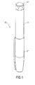
- Pen injection devices such as an exemplary pen injector 50, as shown in FIGS. 1 and 2 , typically comprise a dose knob/button 24, an outer sleeve 13, and a cap 21.
- the dose knob/button 24 allows a user to set the dosage of medication to be injected.
- the outer sleeve 13 is gripped by the user when injecting medication.
- the cap 21 is employed by the user to securely hold the pen injector 50 in a shirt pocket, purse, or other suitable location.
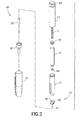
- FIG. 2 is an exploded view of the exemplary drug delivery pen 50 shown in FIG. 1 .
- the dose knob/button 24 has a dual purpose and is used to both set the dosage of the medication to be injected and to inject the dosed medicament via a lead screw 7 and stopper 15 from a medicament cartridge 12, which is attached to the drug delivery pen through a lower housing 17.
- the medicament cartridge 12 is typically a glass tube sealed at one end with a septum 16 and at the other end with the stopper 15
- the dosing and delivery mechanisms are all found within the outer sleeve 13. Those mechanisms are not described in greater detail herein as they are understood by those knowledgeable of the art.
- a pen needle 10 includes a hub 20, a patient needle 11 extending from a patient end of the pen needle, and a septum-penetrating needle cannula 18 disposed within the hub 20 on a non-patient side thereof.
- the septum-penetrating needle cannula 18 is in fluid communication with the patient needle 11.
- the hub 20 is preferably screwed onto the lower housing 17. although other attachment means can be used such as attaching directly to the medicament cartridge 12.
- the septum-penetrating cannula 18 pierces the septum 16, but the septum 16 does not move relative to the medicament cartridge 12.
- the stopper 15, however, is axially displaceable within the medicament cartridge 12 while maintaining a fluid-tight seal.
- the distal movement of the plunger or stopper 15 within the medicament cartridge 12 causes medication to be forced into the patient needle 11 of the hub 20.
- the illustrated pen needle 10 is one example of a pen needle.
- the outer shield 29 can also be used as a handle or grip to screw hub 20 onto or off of pen injector 50.
- An inner shield 28 covers the patient needle 11 within the outer shield 29.
- the inner shield 28 can be secured to the hub 20 to cover the patient needle 11 by any suitable means, such as an interference fit or a snap fit.
- the outer shield 29 and inner shield 28 are removed prior to use.
- the cap 21 fits snugly against outer sleeve 13 to allow a user to securely carry the pen injection device 50.
- Pen needles are usually sold individually packaged inside a plastic cover (such as outer shield 29) with a label covering the opening in the cover to provide a sterility barrier.
- a plastic cover such as outer shield 29
- a label covering the opening in the cover to provide a sterility barrier.
- Recent market research indicates that consumers would prefer a multiple-needle package configuration that includes some provision for containing used pen needles after use. Accordingly, a need exists for a needle dispensing and storing apparatus that stores a plurality of pen needles before and after their use.
- an apparatus for storing and dispensing pen needles for an injection device including a case having dispensing and storage ends for dispensing and storing a plurality of pen needles and a plurality of needle cover units, each pen needle having a patient end and a hub for connection to the injection device, and each needle cover unit having a needle-covering portion for covering a patient end and a hub-covering portion for covering a hub.
- a needle-covering portion covering the needle of one pen needle is coupled with a hub-covering portion covering a hub of another pen needle.
- At least a hub-covering portion covering the hub of a pen needle Prior to use, at least a hub-covering portion covering the hub of a pen needle is exposed to an outside at the dispensing end of the case, and subsequent to use, at least the pen needle is stored in the storage end of the case.
- each pen needle having a patient end and a hub for connection to the injection device
- each needle cover unit having a needle-covering portion for covering a patient end and a hub-covering portion for covering a hub
- the pen needles and needle covering units having a first orientation relative to the case at a dispensing end of the case.
- the method includes the operations of, at the dispensing end of a case, removing a needle cover unit from a pen needle in a dispensing position; connecting the injection device to the hub of the pen needle; at a storage end of the case, inserting a needle cover unit in a second orientation opposite to the first orientation; and inserting the pen needle into the storage end of the case in the second orientation, to cover the patient end of the pen needle with the needle covering portion of the needle cover unit.
- each pen needle having a patient end and a hub for connection to the injection device
- each needle cover unit having a needle-covering portion for covering a patient end and a hub-covering portion for covering a hub.
- the method includes the operations of, at the dispensing end of a case, removing a hub-covering portion of a needle cover unit from a pen needle in a dispensing position; connecting the injection device to the hub of the pen needle; and removing the pen needle, wherein removing the pen needle in the dispensing position automatically advances an unused pen needle and a needle cover unit toward the dispensing end of the case.
- an apparatus for storing and dispensing pen needles for an injection device including a case having dispensing and storage ends for dispensing and storing a plurality of pen needles and a plurality of needle cover units, each pen needle having a patient end and a hub for connection to the injection device, and each needle cover unit having a needle-covering end for covering a patient end and a hub-covering end for covering a hub.
- a needle cover unit covers a hub of a pen needle prior to connection of the pen needle to the injection device, and the needle cover unit covers the patient end of the pen needle during storage in the storage end of the case.
- an apparatus for storing and dispensing pen needles for a pen injection device including a plurality of pen needles, each having a patient end and a hub for connection to the pen injection device; a plurality of needle covers for covering the patient end of the pen needle; a plurality of hub covers, each having a first end for receiving a needle cover and a second end for covering a hub; and a case for storing and dispensing the pluralities of pen needles and needle covers, the case having dispensing and storage ends Prior to use, a hub cover is exposed to an outside of the case at the dispensing end of the case, with the hub cover covering the hub of one of the plurality of pen needles in a dispensing position.
- the pen needle 10 includes the hub 20, and a patient needle 11.
- the septum-penetrating needle cannula 18 disposed within the non-patient end of the hub 20 fluidly communicates with the patient needle 11, and the interior of the non-patient end of the hub 20 includes threads or other features for connection with the pen injector (for example, pend injector 50).
- the pen needle can omit one or more of the above features as long as sterility of both the patient and non-patient ends of the cannula is maintained.
- an exemplary pen needle can also be provided having a hub and cannula assembly only.
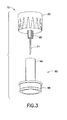
- FIG. 3 is a perspective view of the pen needle 10 and a needle cover unit or cover 80 in accordance with an embodiment of the present invention.
- the cover 80 replaces the inner shield of FIG. 2 in addition to other functions, as will be described in greater detail below.
- the needle 10 includes the hub 20 disposed at a non-patient end thereof.
- a protrusion 68 extends from a patient end of the hub 20 and the patient needle I 1 extends from the protrusion 68.
- the septum-penetrating needle cannula 18 (best shown in FIG. 5 ) disposed within the non-patient end of the hub 20 fluidly communicates with the patient needle 11.
- the cover 80 includes a needle-covering portion 84 and a hub-covering portion 88, as shown in FIG. 3 .
- the needle-covering portion 84 and the hub-covering portion 88 are coupled because they are integrally formed as a unitary structure.
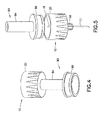
- the shape of the interior of the needle-covering portion 84 corresponds to the shape of the protrusion 68 to facilitate connection between the cover 80 and the pen needle 10. More specifically, in a first orientation of the cover 80 relative to the pen needle 10, the needle-covering portion 84 fits over and connects to the protrusion 68 to cover the patient needle 11, as shown in FIG 4 .
- the connection between the protrusion 68 and the needle-covering portion 84 may be, for example, an interference fit or a snap fit.
- the external shape of the hub-covering portion 88 corresponds to the interior shape of the hub 20 to facilitate connection between the cover 80 and the pen needle 10. More specifically, as shown in FIG 6 , in a second orientation of the cover 80 relative to the pen needle 10, the hub-covering portion 88 fits within and connects to the non-patient end of the hub 20 to cover the hub 20 and the septum-penetrating needle cannula 18.
- the connection between the hub-covering portion 88 and the hub 20 may be, for example, an interference fit or a snap fit.
- a sterility barrier is formed on the non-patient end of the pen needle 10 by the hub-covering portion 88 of the cover 80 being securely connected to the hub 20 on the non-patient side of the pen needle.
- a sterility barrier for the patient end of the pen needle 10 is the needle-covering portion 84, which acts as an inner shield on the patient needle 11 and fits onto the protrusion 68 of the hub 20.
- the sterility barrier for both ends of the pen needle 10 preferably involves a tortuous path.
- a tortuous path closure can be defined as a barrier to airborne microorganisms, accomplished by creating a convoluted pathway to the product (for example, a labyrinth path or a screw-threaded closure).
- a tortuous path is neither airtight nor watertight. It provides a barrier to ingress by microorganisms but not by fluids. Louis Pasteur, in 1861, discovered the principle of tortuous path closures. He determined that a sterilized glass flask with a swan-shaped tortuous neck, even with the end open, would remain sterile.
- microorganisms When microorganisms are out of liquid, they cannot move on their own and cannot turn corners. Rather, most microbes float in the air, often on dust particles. These dust-riding microbes have mass and momentum and settle by gravity. They also have static charges and are attracted to surfaces by intramolecular and electrostatic forces. Another mechanism of particle movement is Brownian motion, This random motion of particles in static airflow also causes microorganisms to impact surfaces.
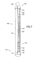
- FIG. 7 is a perspective view of a needle dispensing and storing case 100 in accordance with an embodiment of the present invention.
- the case 100 includes a main body or tube 104, a dispensing end cap 108, a storage end cap 112, and an advancing member or clicker 120.
- the tube 104 includes a slot 122 in which the clicker 120 moves, and a plurality of detents 124 to provide positive stops for the clicker 120 at discrete points along the slot 122.
- the dispensing end cap 108 is disposed at a dispensing end 106 of the tube 104 and selectively covers the dispensing end 106.
- the storage end cap 112 is disposed at a storage end 110 of the tube 104 and selectively covers the storage end 110.
- tube 104 has two ends: the dispensing end 106, where unused pen needles are accessed for use; and the opposing storage end 110, which has a space for the pen needles 10 to be stored after use.
- Each end has a cover 108 and 112 to avoid inadvertent access to the pen needles 10.
- these covers 108 and 112 are attached to the tube 104 in such a way that they can be partially removed to access the pen needles 10 but can still be retained with the tube 104.
- each of the end caps 108 and 112 has at least one cap leg 128 with a cap foot 132 disposed at a distal end thereof.
- each of the dispensing and storage ends of the tube 104 includes at least one cap-retaining structure 134.
- the cap portions of the end caps 108 and 112 are hingedly connected to their respective cap legs 128 by, as a non-limiting example, a living hinge.
- an end cap (108 or 112) to an end of the tube 104
- a user slides the cap foot 132 and the cap leg 128 through the cap-retaining structure 134
- the raised cap foot 132 in conjunction with the cap-retaining structure 136, keeps the cap 108 and/or 112 connected to the tube 104 while providing access to the respective ends.
- respective bases of the end caps 108 and 112 have shapes corresponding to ends of the tube 104, and provide, for example, an interference fit or a snap fit.
- the dispensing end cap 108 and the storage end cap 112 are hingedly connected to the tube 104.
- a living hinge can be used to connect the dispensing end cap 108 and the storage end cap 112 to the tube 104.
- FIG. 8 is a perspective view of the dispensing end 106 of the case 104 and FIG. 9 is an end view of the dispensing end 106 of the case 104.
- the dispensing end 106 of the case 104 includes a plurality of anti-rotation/retaining structures 140.
- the anti-rotation/retaining structures 140 work in conjunction with the hub 20 of a pen needle 10 to prevent rotation of the pen needle 10 when the pen needle 10 is in a dispensing position.
- the anti-rotation/retaining structures 140 prevent the pen needle 10 from rotating and permit the user to connect a pen injector 50 (or a medicament cartridge 12) to the hub 20 by threading the pen injector 50 (or medicament cartridge 12) into the hub 20. While preventing rotation of the pen needle 10 during connection to the pen injector 50, subsequent to the connection, the fit between the anti-rotation/retaining structures 140 and the pen needle 10 permits the user to axially withdraw the combined pen injector 50 and pen needle 10 from the tube 104.
- anti-rotation/retaining structures 140 are similarly disposed at the storage end 110 of the tube 104 to facilitate disconnection between the pen injector 50 and the pen needle 10, and also facilitate storage of the used pen needles 10 in the storage end 110 of the tube 104.
- the structures 140 act as a barrier to prevent easy removal of the used pen needle 10 from the storage end 110 of the tube 104.
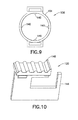
- FIGS. 10 to 12 illustrate the advancing member or clicker 120 in accordance with an embodiment of the present invention.
- the clicker 120 includes a pusher 144 and a pusher top 148.
- a pusher 144 is disposed within the tube 104 and the pusher top 148 is disposed outside the tube 104.
- the user actuates the pusher top 148 to move unused needles toward the dispensing end 106 of the tube 104.
- the pusher 144 has a dispensing end 146 and a storage end 150.
- the pusher 144 includes a cantilevered arm 152 extending from a top portion thereof, and the cantilevered arm 152 includes a detent-engaging member 156 disposed at a distal end thereof
- the detent-engaging member 156 individually engages the detents 124 to provide positive stops for the clicker 120 as the clicker 120 moves along the slot 122.
- the pusher 144 includes an engaging portion 160 to facilitate coupling of the pusher top 148 with the pusher 144.
- the pusher top 148 includes an engagement protrusion 164 extending from a guide 168.
- the engagement protrusion 164 engages the engaging portion 162 to couple the pusher top 148 and the pusher 144. Further, the guide 168 rides in the slot 122 to guide the clicker 120 along the tube 104 and prevent rotation of the pusher top 148 relative to the tube 104.
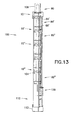
- FIG. 13 is a perspective view of the case 100 and a plurality of pen needles 10 and needle covers 80 in accordance with an embodiment of the present invention.
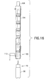
- FIGS. 14-17 are perspective views illustrating operation of the needle dispensing and storing case 100.
- the tube 104, the dispensing end cap 108, and the storage end cap 112 are shown as being opaque. But for illustrative purposes, in FIGS. 13-17 , the tube 104, the dispensing end cap 108, and the storage end cap 112 are shown as being translucent.
- the tube, the dispensing end cap, and the storage end cap may be translucent, transparent, or opaque without departing from the scope of the invention.
- a first pen needle 10 disposed at the dispensing end 106 of the tube 104 in the dispensing position has a first cover 80 connected to the hub 20 and covering the non-patient end of the pen needle 10. Additionally, the patient end of the first pen needle 10 connects to the needle-covering portion 84' of a second cover 80'. Likewise, the second cover 80' also connects to a second pen needle 10' via the hub-covering portion 88'. Moreover, a third cover 80" connects both to the second pen needle 10' and a third pen needle 10". Needle covers 80 and pen needles 10 are similarly connected until a final cover 80" that is adjacent to the clicker 120 connects only to a single pen needle 10'". In other words, the cover 80 covering the patient end of one pen needle 10 also fits into a mating feature on the hub 20 of the non-patient end of the next pen needle 10.
- the user ensures that a pen needle 10 is in the dispensing position by moving the clicker, toward the dispensing end 106 of the tube 104.
- the clicker 120 is adjacent to and contacts the final cover 80"', advancing the clicker 120 toward the dispensing end 106 of the tube 104 advances all needles 10 and needle covers 80 on the dispensing end 146 of the pusher 144 toward the dispensing end 106 of the tube 104.
- the detent engaging member 156 clicks into a detent 124 as each successive cover 80 and pen needle 10 reaches the dispensing position.
- the user opens the dispensing end cap 108 and removes the cover 80, thereby exposing the non-patient end of the pen needle 10.
- the user connects a pen injector (for example, 50) to the non-patient end of the pen needle 10 and removes the pen needle 10 from connection with the cover 80' and from the tube 104, as shown in FIG. 15 .
- a pen injector for example, 50
- the user After performing the injection and closing the dispensing end cap 108, the user opens the storage end cap 112 to store the used pen needle 10, as shown in FIG. 16 .
- the user may insert the cover 80 into the storage end 110 of the tube 104, with the hub-covering portion 88 toward the dispensing end 106 of the tube 104.
- the hub-covering portion 88 of the cover 80 is connectable to the storage end 150 of the pusher 144.
- the user inserts the pen needle 10 into the storage end 110 of the tube 104 to engage the needle-covering portion 84 of the cover 80 with the anti-rotation/retaining structures 140, and unscrews the pen injector from the pen needle 10. Subsequently, as shown in FIG.
- the user closes the storage end cap 112.
- the clicker 120 is moved into the next detent position to push the next unused pen needle (for example, 10') into the dispensing position.
- the user engages the needle-covering portion 84 to the pen needle 10 prior to inserting the engaged assembly into the storage end 110 of the tube 104, to engage the hub 20 with the anti-rotation/retaining structures 140.
- the clicker 120 serves as a separator between used and unused pen needles 10
- the position of the clicker 120 also serves as a visual indicator as to how many unused pen needles remain in the tube 104.
- the tube 104 prior to the removal of the first cover 80, the tube 104 has a space at the storage end 110 thereof to receive a needle cover and/or a pen needle.
- the tube 104 initially, there is no such space at the storage end 110 of the tube 104, and storage space for a used needle cover and/or pen needle is created within the tube 104 by moving the clicker 120 toward the dispensing end 106 of the tube 104.
- One advantage of embodiments of the present invention is that labels are not needed on the hub 20 of a pen needle 10 to provide a sterility barrier. This function is provided by an adjacent cover 80.
- a cover 80 provides a sterility barrier to the patient needle 11 of one pen needle 10 and also provides a sterility barrier to the hub 20 of an adjacent pen needle 10 because the cover 80 is connected to patient end of the one pen needle 10 and is also connected to the hub 20 of the adjacent pen needle 10.
- FIG. 18 is a perspective view of a case 200 in accordance with another embodiment of the present invention.
- the case 200 has a dispensing end 206 for dispensing pen needles and a storage end 210 for storing used pen needles.
- a hub cover 204 is disposed at the dispensing end 206 of the case 200, Additionally, as will be described in greater detail below, toward the storage end 210 of the case 200, a separator 208 indicates the number of remaining pen needles within the case 200.
- FIG. 19 is a perspective view of a pen needle 210 in accordance with an embodiment of the present invention.
- the pen needle 210 includes a hub 21.2 with a plurality of bosses 216 extending radially therefrom.
- a protrusion 220 extends axially from a patient end of the hub 212
- the patient needle 224 extends axially from the protrusion 220.
- a septum-penetrating needle cannula 228 (best shown in FIG. 21 ) extends axially within the hub 212 on a non-patient end of the hub 212.
- the needle cannula 228 is in fluid communication with the patient needle 224.
- FIG. 20 is a perspective view of a needle cover 232 in accordance with an embodiment of the present invention. As shown in FIG. 21 , the needle cover 232 selectively engages the protrusion 220 of the pen needle 210 to protect the patient needle 224 and provide a sterility barrier therefor.
- FIG. 22 is a perspective view of the hub cover 204.
- the hub cover 204 includes a needle cover receiving portion 236 and a hub-covering portion 240.
- the hub-covering portion 240 includes an insertion portion 244.
- the needle cover receiving portion 236 selectively receives a needle cover 232.
- the non-patient end of the hub 212 receives the insertion portion 244 of the hub-covering portion 240 to protect the septum-penetrating needle cannula 228 and provide a sterility barrier therefor.
- the interface between the needle cover 232 and the protrusion 220 and the interface between the hub cover 204 and the non-patient end of the hub 212 are form-fit or interference-fit tortuous paths, thereby providing the respective sterility barriers.
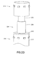
- FIG. 23 is a perspective view of a combination of the pen needle 210, the needle cover 232, the hub cover 204, and another pen needle 210.
- the needle cover 232 and the hub cover 204 form a needle cover unit or cover having a needle-covering portion and a hub-covering portion.
- the upper pen needle 210 engages the needle cover 232.
- the needle cover receiving portion 236 of the hub cover 204 receives the needle cover 232, thus coupling the needle cover 232 and the hub cover 204,
- the non-patient end of the hub 212 of the lower pen needle 210 receives the insertion portion 244 of the hub-covering portion 240 of the hub cover 204.
- a plurality of pen needles 210, needle covers 232, and hub covers 204 can be connected together in a sterile manner.
- the plurality of pen needles 210, needle covers 232, and hub covers 204 are connected in the above-described sterile manner and stored within the case 200, as shown in FIG. 24.
- FIG. 24 is a perspective view in cross-section of the case 200 taken along line 24-24 in FIG. 18 .
- a separator 208 is disposed toward the storage end 210 of the case 200.
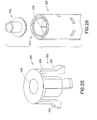
- FIG. 25 is a perspective view of the separator 208.
- the separator 208 includes a needle cover receiving portion 248 and an indicator portion 252 that includes a plurality of cantilevered legs 256, each having a marker or indicator 260 disposed at a free end thereof.
- the indicator 260 indicates the number of unused pen needles 210 remaining in the case 200.
- the user first removes the hub cover 204 from the pen needle 210 disposed at the dispensing end 206 of the case 200 in a dispensing position.
- the user connects a pen injector (for example, pen injector 50) to the pen needle 210 in the dispensing position.
- a pen injector for example, pen injector 50
- FIG. 28 is a partial perspective view of the pen injector 50 connected with a pen needle 210 in the dispensing position.
- the case 200 is shown as being translucent. As one of ordinary skill in the art will appreciate, the case 200 may be translucent, transparent, or opaque without departing from the scope of the invention.
- an interior side of the case 200 has a guide channel 264 recessed therein.
- the guide channel 264 guides movement of a boss 216 of the hub 212 within the case 200, and thus guides movement of the pen needle 210 within the case 200, As will be understood by one of ordinary skill in the art, each boss 216 may have a corresponding guide channel 264 in the case 200 without departing from the scope of the present invention. Nevertheless, for clarity and brevity, FIGS. 28- 31 illustrate an embodiment with a single guide channel 264.
- FIGS. 29-31 are partial plan views of the guide channel 264 illustrating movement of the boss 216 during a dispensing operation.
- FIGS. 28 and 29 illustrate the boss 216 of the pen needle 210 in the dispensing position at a top of a first axial portion 268 of the guide channel 264. Friction between the boss 216 and the top of the first axial portion 268 maintains the boss 216 in the position shown in FIGS. 28 and 29 while the user threads the pen injector 50 into the non-patient end of the hub 212.
- additional clockwise (with respect to the top of the case 200) rotation of the pen injector 50 also rotates the hub 212 circumferentially with respect to the case 200.
- this circumferential hub rotation slides the boss 216 circumferentially in a lateral portion 272 of the guide channel 264 from the top of the first axial portion 268 to the bottom of a second axial portion 276. From this position, the user can remove the pen needle 210 from the case 200 by pulling the pen injector 50 axially with respect to the case 200, as shown in FIG.31 .
- FIG. 32 illustrates an embodiment of the case 200 in which a second guide channel 264 is disposed opposite to the first guide channel 264.
- FIG 32 is a perspective view in cross-section taken along line 24-24 in FIGS. 18 of the case 200.
- the first axial portion 268 extends from the lateral portion 272 substantially down the remainder of the length of the case 200.
- the axial removal of the top pen needle 210 from the case 200 automatically moves the remaining hub covers 204, pen needles 210, and needle covers 232 axially toward the dispensing end 206 of the case 200.
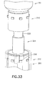
- This axial movement is guided by respective bosses 216 disposed in the guide channel 264, and continues until the boss 216 of the next pen needle 210 moves into the dispensing position at the top of the first axial portion 268 as shown in FIG. 33 .
- the needle cover 232 of the last pen needle 210 is frictionally connected to the separator 208, the axial movement also moves the separator 208.
- the indicators 260 of the separator 208 extend through holes or detents 280 in the side of the case 200 to indicate the number of remaining pen needles within the case 200.
- sloped faces 284 of the indicators 260 (best seen in FIG. 25 ) bear against edges of the detents 280, deflecting or elastically deforming the cantilevered legs 256 and drawing indicators 260 within the case 200.
- the boss 216 of the next pen needle 210 moves into the dispensing position at the top of the first axial portion 268 (as shown, for example in FIG. 33 )
- the indicators 260 are aligned with the next detents 280 and extend therethrough due to the stored energy of the cantilevered legs 256.
- the separator 208 axially moves to a position where the indicators 260 extend through the detents corresponding to the number "4," thereby indicating that four unused pen needles remain within the case 200. Additionally, as will be described in greater detail below, as the separator 208 axially moves to a position where the indicators 260 extend through the next detents 280, space is created between the separator 208 and the storage end 210 of the case 200 for storage of a used pen needle 210.
- the user overcomes the frictional resistance between the needle cover 232 of the removed pen needle 210 and the hub cover 204 disposed at the top of the case 200, as shown in FIG. 35 .
- the user removes the needle cover 232 from the protrusion 220.
- the friction between the needle cover 232 and the protrusion 220 is the greatest.
- the friction between the protrusion 220 and the next hub cover 204 is the greatest.
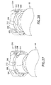
- the storage end 210 of the case 200 includes a plurality of insertion guide channels 288.
- the insertion guide channels 288 may be angled to ease insertion of the bosses 216 of the used pen needle 210 and ensure circumferential orientation of the used pen needle 210.
- the insertion guide channels 288 may be angularly-shaped funnels, thus self aligning the used pen needle 210 during insertion thereof into the storage end 210 of the case 200.
- a storage end 210 of the case 200 also includes a plurality of cantilevered retention units or pawls 292.
- bosses 216 engage respective sloped faces 296 of the pawls 292, and force the cantilevered end of the pawls 292 to extend (deflect or elastically deform) radially with respect to an outer surface of the case 200.
- the sloped faces 296 have a hook on an interior side thereof, so that as the user even further inserts the used pen needle 210 and the bosses 216 pass the hooks on the sloped faces 296, the pawls 292 return to their initial position.
- the hooks engage axial sides of the bosses toward the storage end 210 of the case 200, thereby preventing axial removal of the used pen needle 210 from the storage end 210 of the case 200.
- anti-rotation features are disposed at both ends of the case 200.
- the guide channel 264 prevents rotation of the pen needle 210 to enable attachment of the pen injector 50 to the pen needle 210.
- insertion guide channels 288 and pawls 292 prevent rotation of the used pen needle 210 to enable the detachment of the pen injector 50 from the used pen needle 210. Subsequent to unthreading the pen injector 50 from the used pen needle 210, the user axially pulls the pen injector 50 from the storage end 210 of the case 200.
- the case 200 may have end caps for covering the dispensing and storage ends thereof
- Another advantage of embodiments of the present invention is to provide a compact, convenient apparatus for dispensing unused pen needles and storing used pen needles in a familiar form factor
- a manual lock can be provided on the pen needle storage assembly, thereby allowing the user to manually lock the storage assembly to allow for safe disposal thereof.
- a lock becomes functional only after the last pen needle has been used.
- only the last-used pen needle is always accessible, thereby providing an available pen needle in case of emergency.
- the other used pen needles are locked into the storage end of the case and are no longer accessible.
Landscapes
- Health & Medical Sciences (AREA)
- Engineering & Computer Science (AREA)
- Heart & Thoracic Surgery (AREA)
- Vascular Medicine (AREA)
- Anesthesiology (AREA)
- Biomedical Technology (AREA)
- Diabetes (AREA)
- Hematology (AREA)
- Life Sciences & Earth Sciences (AREA)
- Animal Behavior & Ethology (AREA)
- General Health & Medical Sciences (AREA)
- Public Health (AREA)
- Veterinary Medicine (AREA)
- Environmental & Geological Engineering (AREA)
- Infusion, Injection, And Reservoir Apparatuses (AREA)
Abstract
Description
- This application claims priority under 35 USC §119(e) from
U.S. Provisional Patent Application Serial No. 61/344,538, filed on August 16, 2010 U.S. Provisional Patent Application Serial No. 61/344,540, filed on August 16, 2010 - The present invention relates to needles for a pen injection device, and more particularly, to an apparatus for dispensing and storing needles for a pen injection device.
- Medication delivery pens are used for self-injection of precisely measured doses of medication. Pens are widely used, for example, by diabetics to self-inject insulin. A typical medication delivery pen includes a cartridge that contains a volume of liquid medication sufficient for several doses. Using a pen needle attached to the pen device, the dose is injected into a tissue area, such as the intramuscular tissue layer, the subcutaneous tissue layer, or the intradermal tissue layer.
- The assembly and operation of a typical pen injection device is described in commonly-assigned
U.S. Patent No. 7,645,264 , which is hereby incorporated by reference in its entirety. - Pen injection devices, such as an
exemplary pen injector 50, as shown inFIGS. 1 and2 , typically comprise a dose knob/button 24, anouter sleeve 13, and acap 21. The dose knob/button 24 allows a user to set the dosage of medication to be injected. Theouter sleeve 13 is gripped by the user when injecting medication. Thecap 21 is employed by the user to securely hold thepen injector 50 in a shirt pocket, purse, or other suitable location. -
FIG. 2 is an exploded view of the exemplarydrug delivery pen 50 shown inFIG. 1 . The dose knob/button 24 has a dual purpose and is used to both set the dosage of the medication to be injected and to inject the dosed medicament via a lead screw 7 andstopper 15 from amedicament cartridge 12, which is attached to the drug delivery pen through alower housing 17. Themedicament cartridge 12 is typically a glass tube sealed at one end with aseptum 16 and at the other end with thestopper 15 In standard drug delivery pens, the dosing and delivery mechanisms are all found within theouter sleeve 13. Those mechanisms are not described in greater detail herein as they are understood by those knowledgeable of the art. - A
pen needle 10 includes ahub 20, apatient needle 11 extending from a patient end of the pen needle, and a septum-penetratingneedle cannula 18 disposed within thehub 20 on a non-patient side thereof. The septum-penetratingneedle cannula 18 is in fluid communication with thepatient needle 11. Thehub 20 is preferably screwed onto thelower housing 17. although other attachment means can be used such as attaching directly to themedicament cartridge 12. In attaching thehub 20 to thelower housing 17 ormedicament cartridge 12, the septum-penetratingcannula 18 pierces theseptum 16, but theseptum 16 does not move relative to themedicament cartridge 12. Thestopper 15, however, is axially displaceable within themedicament cartridge 12 while maintaining a fluid-tight seal. The distal movement of the plunger orstopper 15 within the medicament cartridge 12 (due to advancement of the lead screw 7) causes medication to be forced into thepatient needle 11 of thehub 20. The illustratedpen needle 10 is one example of a pen needle. - To protect a user, or anyone who handles the
pen injector 50, anouter shield 29, which attaches to thehub 20, covers thehub 20. Theouter shield 29 can also be used as a handle or grip to screwhub 20 onto or off ofpen injector 50. Aninner shield 28 covers thepatient needle 11 within theouter shield 29. Theinner shield 28 can be secured to thehub 20 to cover thepatient needle 11 by any suitable means, such as an interference fit or a snap fit. Theouter shield 29 andinner shield 28 are removed prior to use. Thecap 21 fits snugly againstouter sleeve 13 to allow a user to securely carry thepen injection device 50. - Pen needles are usually sold individually packaged inside a plastic cover (such as outer shield 29) with a label covering the opening in the cover to provide a sterility barrier. Recent market research indicates that consumers would prefer a multiple-needle package configuration that includes some provision for containing used pen needles after use. Accordingly, a need exists for a needle dispensing and storing apparatus that stores a plurality of pen needles before and after their use.
- It is an aspect of the present invention to provide an apparatus for storing pen needles. More specifically, it is an aspect of the present invention to provide an apparatus for storing pen needles prior to their use as well as subsequent to their use. Additionally, it is an aspect of the present invention to provide an apparatus for dispensing pen needles for use with a pen injection device.
- The foregoing and/or other aspects of the present invention are achieved by providing an apparatus for storing and dispensing pen needles for an injection device, including a case having dispensing and storage ends for dispensing and storing a plurality of pen needles and a plurality of needle cover units, each pen needle having a patient end and a hub for connection to the injection device, and each needle cover unit having a needle-covering portion for covering a patient end and a hub-covering portion for covering a hub. A needle-covering portion covering the needle of one pen needle is coupled with a hub-covering portion covering a hub of another pen needle. Prior to use, at least a hub-covering portion covering the hub of a pen needle is exposed to an outside at the dispensing end of the case, and subsequent to use, at least the pen needle is stored in the storage end of the case.
- The foregoing and/or other aspects of the present invention are also achieved by providing a method for dispensing and storing needle cover units and pen needles for an injection device, each pen needle having a patient end and a hub for connection to the injection device, and each needle cover unit having a needle-covering portion for covering a patient end and a hub-covering portion for covering a hub, the pen needles and needle covering units having a first orientation relative to the case at a dispensing end of the case. The method includes the operations of, at the dispensing end of a case, removing a needle cover unit from a pen needle in a dispensing position; connecting the injection device to the hub of the pen needle; at a storage end of the case, inserting a needle cover unit in a second orientation opposite to the first orientation; and inserting the pen needle into the storage end of the case in the second orientation, to cover the patient end of the pen needle with the needle covering portion of the needle cover unit.
- The foregoing and/or other aspects of the present invention are also achieved by providing a method for dispensing and storing needle cover units and pen needles for an injection device, each pen needle having a patient end and a hub for connection to the injection device, and each needle cover unit having a needle-covering portion for covering a patient end and a hub-covering portion for covering a hub. The method includes the operations of, at the dispensing end of a case, removing a hub-covering portion of a needle cover unit from a pen needle in a dispensing position; connecting the injection device to the hub of the pen needle; and removing the pen needle, wherein removing the pen needle in the dispensing position automatically advances an unused pen needle and a needle cover unit toward the dispensing end of the case.
- The foregoing and/or other aspects of the present invention are also achieved by providing an apparatus for storing and dispensing pen needles for an injection device, the apparatus including a case having dispensing and storage ends for dispensing and storing a plurality of pen needles and a plurality of needle cover units, each pen needle having a patient end and a hub for connection to the injection device, and each needle cover unit having a needle-covering end for covering a patient end and a hub-covering end for covering a hub. A needle cover unit covers a hub of a pen needle prior to connection of the pen needle to the injection device, and the needle cover unit covers the patient end of the pen needle during storage in the storage end of the case.
- The foregoing and/or other aspects of the present invention are also achieved by providing an apparatus for storing and dispensing pen needles for a pen injection device, the apparatus including a plurality of pen needles, each having a patient end and a hub for connection to the pen injection device; a plurality of needle covers for covering the patient end of the pen needle; a plurality of hub covers, each having a first end for receiving a needle cover and a second end for covering a hub; and a case for storing and dispensing the pluralities of pen needles and needle covers, the case having dispensing and storage ends Prior to use, a hub cover is exposed to an outside of the case at the dispensing end of the case, with the hub cover covering the hub of one of the plurality of pen needles in a dispensing position. Subsequent to the removal of the exposed hub cover, removal of the pen needle in the dispensing position from the case automatically moves the remaining hub covers, pen needles, and needle covers toward the dispensing end of the case and creates a space in the case at the storage end of the case for insertion of the removed pen needle.
- Additional and/or other aspects and advantages of the present invention will be set forth in part in the description that follows and, in part, will be apparent from the description, or may be learned by practice of the invention.
- The above and/or other aspects and advantages of embodiments of the invention will become apparent and more readily appreciated from the following detailed description, taken in conjunction with the accompanying drawings, in which:
-
FIG. 1 is a perspective view of an exemplary drug delivery pen; -
FIG. 2 is an exploded view of the exemplary drug delivery pen ofFIG. 1 ; -
FIG. 3 is a perspective view of a pen needle and a needle cover in accordance with an embodiment of the present invention; -
FIG. 4 is a perspective view of the pen needle and needle cover ofFIG. 3 engaged to cover a patient end of the pen needle; -
FIG. 5 is a perspective view of the pen needle and needle cover ofFIG. 3 illustrating an arrangement to cover a non-patient end of the pen needle; -
FIG. 6 is a perspective view of the pen needle and needle cover ofFIG. 3 engaged to cover a non-patient end of the pen needle; -
FIG. 7 is a perspective view of a case in accordance with an embodiment of the present invention; -
FIG. 8 is a perspective view of a dispensing end of the case ofFIG. 7 ; -
FIG. 9 is an end view of the dispensing end of the case ofFIG. 7 ; -
FIG. 10 is a perspective view of an advancing member of the case ofFIG. 7 ; -
FIG 11 is a perspective view of a pusher of the advancing member ofFIG. 10 ; -
FIG. 12 is a perspective view of the bottom of a pusher top of the advancing member ofFIG. 10 ; -
FIG. 13 is a perspective view of the case ofFIG. 7 and a plurality of pen needles and needle covers ofFIG. 3 in accordance with an embodiment of the present invention; -
FIGS. 14-17 are perspective views illustrating operation of the case ofFIG. 7 ; -
FIG. 18 is a perspective view of a case in accordance with another embodiment of the present invention; -
FIG. 19 is a perspective view of a pen needle in accordance with an embodiment of the present invention; -
FIG. 20 is a perspective view of a needle cover in accordance with an embodiment of the present invention; -
FIG. 21 is a perspective view of a combination of the pen needle ofFIG. 19 and the needle cover ofFIG. 20 ; -
FIG. 22 is a perspective view of a hub cover in accordance with an embodiment of the present invention; -
FIG. 23 is a perspective view of a combination of the pen needle ofFIG. 19 , the needle cover ofFIG. 20 , the hub cover ofFIG. 22 , and another pen needle ofFIG. 19 ; -
FIG. 24 is a perspective view in cross-section of the case ofFIG. 18 taken along line 24-24 inFIG. 18 ; -
FIG. 25 is a perspective view of a separator in accordance with an embodiment of the present invention; -
FIG, 26 is a partial perspective view of the hub cover ofFIG. 22 removed from the case ofFIG. 18 ; -
FIG. 27 is a partial perspective view of the case ofFIG. 18 and a pen injector; -
FIG. 28 is a partial perspective view of the pen injector ofFIG. 27 connected with a pen needle ofFIG. 19 within the case ofFIG. 18 ; -
FIGS. 29-31 are partial plan views of a guide channel of the case ofFIG. 18 ; -
FIG. 32 is a perspective view in cross-section of the case ofFIG. 18 with no pen needles disposed therein taken along line 24-24 inFIG. 18 ; -
FIG. 33 is a perspective view of the pen injector ofFIG. 27 , the pen needle ofFIG. 19 , the needle cover ofFIG. 20 , the hub cover ofFIG. 22 , another pen needle ofFIG. 19 , and the case ofFIG. 18 ; -
FIG. 34 is a partial perspective view of the case ofFIG. 18 ; -
FIG. 35 is a partial perspective view of removal of a pen needle ofFIG. 19 and cover ofFIG. 20 from a hub cover ofFIG. 22 ; and -
FIGS. 36-38 are partial perspective views of insertion of a pen needle ofFIG. 19 into the storage end of the case ofFIG. 18 . - Reference will now be made in detail to embodiments of the present invention, examples of which are illustrated in the accompanying drawings, wherein like reference numerals refer to the like elements throughout. The embodiments described exemplify, but do not limit the present invention by referring to the drawings. As will be understood by one skilled in the art, terms such as up, down, bottom, and top are relative, and are employed to aid illustration, but are not limiting
- As noted above, the
pen needle 10 includes thehub 20, and apatient needle 11. The septum-penetratingneedle cannula 18 disposed within the non-patient end of thehub 20 fluidly communicates with thepatient needle 11, and the interior of the non-patient end of thehub 20 includes threads or other features for connection with the pen injector (for example, pend injector 50). In these or other exemplary embodiments of the present invention the pen needle can omit one or more of the above features as long as sterility of both the patient and non-patient ends of the cannula is maintained. For example, an exemplary pen needle can also be provided having a hub and cannula assembly only. -
FIG. 3 is a perspective view of thepen needle 10 and a needle cover unit or cover 80 in accordance with an embodiment of the present invention. Thecover 80 replaces the inner shield ofFIG. 2 in addition to other functions, as will be described in greater detail below. As shown inFIG. 3 , theneedle 10 includes thehub 20 disposed at a non-patient end thereof. Aprotrusion 68 extends from a patient end of thehub 20 and the patient needle I 1 extends from theprotrusion 68. The septum-penetrating needle cannula 18 (best shown inFIG. 5 ) disposed within the non-patient end of thehub 20 fluidly communicates with thepatient needle 11. - The
cover 80 includes a needle-coveringportion 84 and a hub-coveringportion 88, as shown inFIG. 3 . Thus, in this embodiment, the needle-coveringportion 84 and the hub-coveringportion 88 are coupled because they are integrally formed as a unitary structure. The shape of the interior of the needle-covering portion 84 (best seen inFIG. 5 ) corresponds to the shape of theprotrusion 68 to facilitate connection between thecover 80 and thepen needle 10. More specifically, in a first orientation of thecover 80 relative to thepen needle 10, the needle-coveringportion 84 fits over and connects to theprotrusion 68 to cover thepatient needle 11, as shown inFIG 4 . The connection between theprotrusion 68 and the needle-coveringportion 84 may be, for example, an interference fit or a snap fit. - Similar to the connection between the
protrusion 68 and the needle-coveringportion 84, as shown inFIG. 5 , the external shape of the hub-coveringportion 88 corresponds to the interior shape of thehub 20 to facilitate connection between thecover 80 and thepen needle 10. More specifically, as shown inFIG 6 , in a second orientation of thecover 80 relative to thepen needle 10, the hub-coveringportion 88 fits within and connects to the non-patient end of thehub 20 to cover thehub 20 and the septum-penetratingneedle cannula 18. The connection between the hub-coveringportion 88 and thehub 20 may be, for example, an interference fit or a snap fit. - A sterility barrier is formed on the non-patient end of the
pen needle 10 by the hub-coveringportion 88 of thecover 80 being securely connected to thehub 20 on the non-patient side of the pen needle. Similarly, a sterility barrier for the patient end of thepen needle 10 is the needle-coveringportion 84, which acts as an inner shield on thepatient needle 11 and fits onto theprotrusion 68 of thehub 20. The sterility barrier for both ends of thepen needle 10 preferably involves a tortuous path. - A tortuous path closure can be defined as a barrier to airborne microorganisms, accomplished by creating a convoluted pathway to the product (for example, a labyrinth path or a screw-threaded closure). A tortuous path is neither airtight nor watertight. It provides a barrier to ingress by microorganisms but not by fluids. Louis Pasteur, in 1861, discovered the principle of tortuous path closures. He determined that a sterilized glass flask with a swan-shaped tortuous neck, even with the end open, would remain sterile.
- When microorganisms are out of liquid, they cannot move on their own and cannot turn corners. Rather, most microbes float in the air, often on dust particles. These dust-riding microbes have mass and momentum and settle by gravity. They also have static charges and are attracted to surfaces by intramolecular and electrostatic forces. Another mechanism of particle movement is Brownian motion, This random motion of particles in static airflow also causes microorganisms to impact surfaces.
- With a tortuous path or labyrinth enclosure, air pressure changes cause air to move in and out of the enclosed volume. While the air moves around the turns, the organisms impact surfaces, causing them to be "filtered" out of the air. With the low air velocities caused by normal environmental pressure changes, the bacteria tend to stay where they have landed. The sterility barriers of these tortuous path closure systems are created by the repeated turns microorganisms would have to make to breach product sterility. The small air volume in many tortuous path products also helps by reducing the air volume that is exchanged with the atmosphere.
-
FIG. 7 is a perspective view of a needle dispensing and storingcase 100 in accordance with an embodiment of the present invention. As shown inFIG. 7 , thecase 100 includes a main body ortube 104, a dispensingend cap 108, astorage end cap 112, and an advancing member orclicker 120. Thetube 104 includes aslot 122 in which theclicker 120 moves, and a plurality ofdetents 124 to provide positive stops for theclicker 120 at discrete points along theslot 122. The dispensingend cap 108 is disposed at a dispensingend 106 of thetube 104 and selectively covers the dispensingend 106. Similarly, thestorage end cap 112 is disposed at astorage end 110 of thetube 104 and selectively covers thestorage end 110. In other words,tube 104 has two ends: the dispensingend 106, where unused pen needles are accessed for use; and the opposingstorage end 110, which has a space for the pen needles 10 to be stored after use. Each end has acover covers tube 104 in such a way that they can be partially removed to access the pen needles 10 but can still be retained with thetube 104. - As shown in
FIG. 7 , each of the end caps 108 and 112 has at least onecap leg 128 with acap foot 132 disposed at a distal end thereof. Correspondingly, each of the dispensing and storage ends of thetube 104 includes at least one cap-retainingstructure 134. The cap portions of the end caps 108 and 112 are hingedly connected to theirrespective cap legs 128 by, as a non-limiting example, a living hinge. - To secure an end cap (108 or 112) to an end of the
tube 104, a user slides thecap foot 132 and thecap leg 128 through the cap-retainingstructure 134, When a user disengages the dispensingend cap 108 and/or thestorage end cap 112 from their respective ends, the raisedcap foot 132, in conjunction with the cap-retaining structure 136, keeps thecap 108 and/or 112 connected to thetube 104 while providing access to the respective ends. In addition, according to one embodiment, respective bases of the end caps 108 and 112 have shapes corresponding to ends of thetube 104, and provide, for example, an interference fit or a snap fit. - According to another embodiment (best shown in
FIGS. 14-16 ), the dispensingend cap 108 and thestorage end cap 112 are hingedly connected to thetube 104. A living hinge can be used to connect the dispensingend cap 108 and thestorage end cap 112 to thetube 104. -
FIG. 8 is a perspective view of the dispensingend 106 of thecase 104 andFIG. 9 is an end view of the dispensingend 106 of thecase 104. As illustrated inFIGS. 8 and9 , the dispensingend 106 of thecase 104 includes a plurality of anti-rotation/retainingstructures 140. At the dispensingend 106 of thecase 104, the anti-rotation/retainingstructures 140 work in conjunction with thehub 20 of apen needle 10 to prevent rotation of thepen needle 10 when thepen needle 10 is in a dispensing position. For example, when thepen needle 10 is in the dispensing position and the anti-rotation/retainingstructures 140 are engaged with thehub 20, the anti-rotation/retainingstructures 140 prevent thepen needle 10 from rotating and permit the user to connect a pen injector 50 (or a medicament cartridge 12) to thehub 20 by threading the pen injector 50 (or medicament cartridge 12) into thehub 20. While preventing rotation of thepen needle 10 during connection to thepen injector 50, subsequent to the connection, the fit between the anti-rotation/retainingstructures 140 and thepen needle 10 permits the user to axially withdraw the combinedpen injector 50 andpen needle 10 from thetube 104. - Though not illustrated, anti-rotation/retaining
structures 140 are similarly disposed at thestorage end 110 of thetube 104 to facilitate disconnection between thepen injector 50 and thepen needle 10, and also facilitate storage of the used pen needles 10 in thestorage end 110 of thetube 104. For example, as discussed in greater detail below, once thehub 20 of a givenpen needle 10 is inserted into thestorage end 110 of thetube 104 past the anti-rotation/retainingstructures 140, thestructures 140 act as a barrier to prevent easy removal of the usedpen needle 10 from thestorage end 110 of thetube 104. -
FIGS. 10 to 12 illustrate the advancing member orclicker 120 in accordance with an embodiment of the present invention. As shown inFIG. 10 , theclicker 120 includes apusher 144 and apusher top 148. In general, apusher 144 is disposed within thetube 104 and thepusher top 148 is disposed outside thetube 104. As will be discussed in greater detail below, the user actuates thepusher top 148 to move unused needles toward the dispensingend 106 of thetube 104. - The
pusher 144 has a dispensingend 146 and astorage end 150. AsFIG. 11 also illustrates, thepusher 144 includes acantilevered arm 152 extending from a top portion thereof, and thecantilevered arm 152 includes a detent-engagingmember 156 disposed at a distal end thereof In use, the detent-engagingmember 156 individually engages thedetents 124 to provide positive stops for theclicker 120 as theclicker 120 moves along theslot 122. Additionally, thepusher 144 includes an engagingportion 160 to facilitate coupling of thepusher top 148 with thepusher 144. Correspondingly, as shown inFIG. 12 , thepusher top 148 includes anengagement protrusion 164 extending from aguide 168. Theengagement protrusion 164 engages the engaging portion 162 to couple thepusher top 148 and thepusher 144. Further, theguide 168 rides in theslot 122 to guide theclicker 120 along thetube 104 and prevent rotation of thepusher top 148 relative to thetube 104. -
FIG. 13 is a perspective view of thecase 100 and a plurality of pen needles 10 and needle covers 80 in accordance with an embodiment of the present invention.FIGS. 14-17 are perspective views illustrating operation of the needle dispensing and storingcase 100. InFIGS. 7-9 , thetube 104, the dispensingend cap 108, and thestorage end cap 112 are shown as being opaque. But for illustrative purposes, inFIGS. 13-17 , thetube 104, the dispensingend cap 108, and thestorage end cap 112 are shown as being translucent. As one of ordinary skill in the art will appreciate, the tube, the dispensing end cap, and the storage end cap may be translucent, transparent, or opaque without departing from the scope of the invention. - As shown in
FIG. 13 , afirst pen needle 10 disposed at the dispensingend 106 of thetube 104 in the dispensing position has afirst cover 80 connected to thehub 20 and covering the non-patient end of thepen needle 10. Additionally, the patient end of thefirst pen needle 10 connects to the needle-covering portion 84' of a second cover 80'. Likewise, the second cover 80' also connects to a second pen needle 10' via the hub-covering portion 88'. Moreover, athird cover 80" connects both to the second pen needle 10' and athird pen needle 10". Needle covers 80 and pen needles 10 are similarly connected until afinal cover 80" that is adjacent to theclicker 120 connects only to a single pen needle 10'". In other words, thecover 80 covering the patient end of onepen needle 10 also fits into a mating feature on thehub 20 of the non-patient end of thenext pen needle 10. - To use the needle dispensing and storing
case 100, the user ensures that apen needle 10 is in the dispensing position by moving the clicker, toward the dispensingend 106 of thetube 104. Put differently, because theclicker 120 is adjacent to and contacts thefinal cover 80"', advancing theclicker 120 toward the dispensingend 106 of thetube 104 advances allneedles 10 and needle covers 80 on the dispensingend 146 of thepusher 144 toward the dispensingend 106 of thetube 104. During use, as the user advances theclicker 120 toward the dispensingend 106 of thetube 104, thedetent engaging member 156 clicks into adetent 124 as eachsuccessive cover 80 andpen needle 10 reaches the dispensing position. - Subsequently, as shown in
FIG, 14 , the user opens the dispensingend cap 108 and removes thecover 80, thereby exposing the non-patient end of thepen needle 10. Next, the user connects a pen injector (for example, 50) to the non-patient end of thepen needle 10 and removes thepen needle 10 from connection with the cover 80' and from thetube 104, as shown inFIG. 15 . - After performing the injection and closing the dispensing
end cap 108, the user opens thestorage end cap 112 to store the usedpen needle 10, as shown inFIG. 16 . Optionally, the user may insert thecover 80 into thestorage end 110 of thetube 104, with the hub-coveringportion 88 toward the dispensingend 106 of thetube 104. According to one embodiment, the hub-coveringportion 88 of thecover 80 is connectable to thestorage end 150 of thepusher 144. Next, the user inserts thepen needle 10 into thestorage end 110 of thetube 104 to engage the needle-coveringportion 84 of thecover 80 with the anti-rotation/retainingstructures 140, and unscrews the pen injector from thepen needle 10. Subsequently, as shown inFIG. 17 , the user closes thestorage end cap 112. For further use, theclicker 120 is moved into the next detent position to push the next unused pen needle (for example, 10') into the dispensing position. According to one embodiment, the user engages the needle-coveringportion 84 to thepen needle 10 prior to inserting the engaged assembly into thestorage end 110 of thetube 104, to engage thehub 20 with the anti-rotation/retainingstructures 140. - As additional pen needles 10 are used, they can be inserted into the
storage end 110 of thetube 104, pushing previously stored used pen needles 10 further into thetube 104 in the space created by moving theclicker 120 toward the dispensingend 106 of thetube 104. Thus, in addition to moving unused pen needles 10, theclicker 120 serves as a separator between used and unused pen needles 10, As theclicker 120 is advanced to adetent 124, the position of theclicker 120 also serves as a visual indicator as to how many unused pen needles remain in thetube 104. - According to one embodiment, as shown, for example, in
FIG. 13 , prior to the removal of thefirst cover 80, thetube 104 has a space at thestorage end 110 thereof to receive a needle cover and/or a pen needle. According to another embodiment, initially, there is no such space at thestorage end 110 of thetube 104, and storage space for a used needle cover and/or pen needle is created within thetube 104 by moving theclicker 120 toward the dispensingend 106 of thetube 104. - One advantage of embodiments of the present invention is that labels are not needed on the
hub 20 of apen needle 10 to provide a sterility barrier. This function is provided by anadjacent cover 80. Put another way, acover 80 provides a sterility barrier to thepatient needle 11 of onepen needle 10 and also provides a sterility barrier to thehub 20 of anadjacent pen needle 10 because thecover 80 is connected to patient end of the onepen needle 10 and is also connected to thehub 20 of theadjacent pen needle 10. -
FIG. 18 is a perspective view of acase 200 in accordance with another embodiment of the present invention. Thecase 200 has a dispensingend 206 for dispensing pen needles and astorage end 210 for storing used pen needles. As shown inFIG. 18 , ahub cover 204 is disposed at the dispensingend 206 of thecase 200, Additionally, as will be described in greater detail below, toward thestorage end 210 of thecase 200, aseparator 208 indicates the number of remaining pen needles within thecase 200. -
FIG. 19 is a perspective view of apen needle 210 in accordance with an embodiment of the present invention. As shown inFIG. 19 , thepen needle 210 includes a hub 21.2 with a plurality ofbosses 216 extending radially therefrom. Additionally, aprotrusion 220 extends axially from a patient end of thehub 212, and thepatient needle 224 extends axially from theprotrusion 220. Similar to thepen needle 10 described above, a septum-penetrating needle cannula 228 (best shown inFIG. 21 ) extends axially within thehub 212 on a non-patient end of thehub 212. Theneedle cannula 228 is in fluid communication with thepatient needle 224. -
FIG. 20 is a perspective view of aneedle cover 232 in accordance with an embodiment of the present invention. As shown inFIG. 21 , theneedle cover 232 selectively engages theprotrusion 220 of thepen needle 210 to protect thepatient needle 224 and provide a sterility barrier therefor. -
FIG. 22 is a perspective view of thehub cover 204. As shown inFIG. 22 , thehub cover 204 includes a needlecover receiving portion 236 and a hub-coveringportion 240. The hub-coveringportion 240 includes aninsertion portion 244. As described in greater detail below, the needlecover receiving portion 236 selectively receives aneedle cover 232. In addition, the non-patient end of thehub 212 receives theinsertion portion 244 of the hub-coveringportion 240 to protect the septum-penetratingneedle cannula 228 and provide a sterility barrier therefor. - According to one embodiment, the interface between the
needle cover 232 and theprotrusion 220 and the interface between thehub cover 204 and the non-patient end of thehub 212 are form-fit or interference-fit tortuous paths, thereby providing the respective sterility barriers. -
FIG. 23 is a perspective view of a combination of thepen needle 210, theneedle cover 232, thehub cover 204, and anotherpen needle 210. Collectively, theneedle cover 232 and thehub cover 204 form a needle cover unit or cover having a needle-covering portion and a hub-covering portion. As shown inFIG. 23 , theupper pen needle 210 engages theneedle cover 232. In turn, the needlecover receiving portion 236 of thehub cover 204 receives theneedle cover 232, thus coupling theneedle cover 232 and thehub cover 204, Further, the non-patient end of thehub 212 of thelower pen needle 210 receives theinsertion portion 244 of the hub-coveringportion 240 of thehub cover 204. In this way, a plurality of pen needles 210, needle covers 232, and hub covers 204 can be connected together in a sterile manner.. - According to one embodiment, the plurality of pen needles 210, needle covers 232, and hub covers 204 are connected in the above-described sterile manner and stored within the
case 200, as shown inFIG. 24. FIG. 24 is a perspective view in cross-section of thecase 200 taken along line 24-24 inFIG. 18 . In such a configuration, when thecase 200 is full of unusedpert needles 210, aseparator 208 is disposed toward thestorage end 210 of thecase 200. -
FIG. 25 is a perspective view of theseparator 208. As shown inFIG. 25 theseparator 208 includes a needlecover receiving portion 248 and anindicator portion 252 that includes a plurality ofcantilevered legs 256, each having a marker orindicator 260 disposed at a free end thereof. As described in greater detail below, theindicator 260 indicates the number of unused pen needles 210 remaining in thecase 200. - To use the
case 200, as shown inFIG. 26 , the user first removes thehub cover 204 from thepen needle 210 disposed at the dispensingend 206 of thecase 200 in a dispensing position. Next, as shown inFIGS. 27 and28 , the user connects a pen injector (for example, pen injector 50) to thepen needle 210 in the dispensing position. -
FIG. 28 is a partial perspective view of thepen injector 50 connected with apen needle 210 in the dispensing position. For illustrative purposes, inFIGS. 28 and32 , thecase 200 is shown as being translucent. As one of ordinary skill in the art will appreciate, thecase 200 may be translucent, transparent, or opaque without departing from the scope of the invention. As shown inFIG. 28 , an interior side of thecase 200 has aguide channel 264 recessed therein. Theguide channel 264 guides movement of aboss 216 of thehub 212 within thecase 200, and thus guides movement of thepen needle 210 within thecase 200, As will be understood by one of ordinary skill in the art, eachboss 216 may have acorresponding guide channel 264 in thecase 200 without departing from the scope of the present invention. Nevertheless, for clarity and brevity,FIGS. 28- 31 illustrate an embodiment with asingle guide channel 264. -
FIGS. 29-31 are partial plan views of theguide channel 264 illustrating movement of theboss 216 during a dispensing operation.FIGS. 28 and29 illustrate theboss 216 of thepen needle 210 in the dispensing position at a top of a firstaxial portion 268 of theguide channel 264. Friction between theboss 216 and the top of the firstaxial portion 268 maintains theboss 216 in the position shown inFIGS. 28 and29 while the user threads thepen injector 50 into the non-patient end of thehub 212. Once thepen injector 50 and thepen needle 210 are connected tightly, however, additional clockwise (with respect to the top of the case 200) rotation of thepen injector 50 also rotates thehub 212 circumferentially with respect to thecase 200. As shown inFIGS. 29 and 30 , this circumferential hub rotation slides theboss 216 circumferentially in alateral portion 272 of theguide channel 264 from the top of the firstaxial portion 268 to the bottom of a secondaxial portion 276. From this position, the user can remove thepen needle 210 from thecase 200 by pulling thepen injector 50 axially with respect to thecase 200, as shown inFIG.31 . - For instructive purposes,
FIG. 32 illustrates an embodiment of thecase 200 in which asecond guide channel 264 is disposed opposite to thefirst guide channel 264.FIG 32 is a perspective view in cross-section taken along line 24-24 inFIGS. 18 of thecase 200. As shown inFIG. 32 , the firstaxial portion 268 extends from thelateral portion 272 substantially down the remainder of the length of thecase 200. - Because the pen needles 210, needle covers 232, and hub covers 204 are frictionally connected, the axial removal of the
top pen needle 210 from thecase 200 automatically moves the remaining hub covers 204, pen needles 210, and needle covers 232 axially toward the dispensingend 206 of thecase 200. This axial movement is guided byrespective bosses 216 disposed in theguide channel 264, and continues until theboss 216 of thenext pen needle 210 moves into the dispensing position at the top of the firstaxial portion 268 as shown inFIG. 33 . Further, because theneedle cover 232 of thelast pen needle 210 is frictionally connected to theseparator 208, the axial movement also moves theseparator 208. - At rest, as shown in
FIG. 34 , theindicators 260 of theseparator 208 extend through holes ordetents 280 in the side of thecase 200 to indicate the number of remaining pen needles within thecase 200. During axial movement of theseparator 208 toward the dispensingend 206 of thecase 200, sloped faces 284 of the indicators 260 (best seen inFIG. 25 ) bear against edges of thedetents 280, deflecting or elastically deforming thecantilevered legs 256 and drawingindicators 260 within thecase 200. When theboss 216 of thenext pen needle 210 moves into the dispensing position at the top of the first axial portion 268 (as shown, for example inFIG. 33 ), theindicators 260 are aligned with thenext detents 280 and extend therethrough due to the stored energy of the cantileveredlegs 256. - In the illustrated embodiments, there are initially five unused pen needles 210 stored within the
case 200. As shown inFIG, 34 , after thefirst pen needle 210 is removed from thecase 200, theseparator 208 axially moves to a position where theindicators 260 extend through the detents corresponding to the number "4," thereby indicating that four unused pen needles remain within thecase 200. Additionally, as will be described in greater detail below, as theseparator 208 axially moves to a position where theindicators 260 extend through thenext detents 280, space is created between theseparator 208 and thestorage end 210 of thecase 200 for storage of a usedpen needle 210. - After the
boss 216 of thenext pen needle 210 moves into the dispensing position at the top of the firstaxial portion 268, the user overcomes the frictional resistance between theneedle cover 232 of the removedpen needle 210 and thehub cover 204 disposed at the top of thecase 200, as shown inFIG. 35 . Subsequently, to use thepen needle 210 connected to thepen injector 50, the user removes theneedle cover 232 from theprotrusion 220. To ensure the above-described axial movement of the hub covers 204, pen needles 210, needle covers 232, and theseparator 208 during removal of apen needle 210 from thecase 200, in a hierarchy of tolerances among the pieces, the friction between theneedle cover 232 and theprotrusion 220 is the greatest. In an alternative embodiment, in which needle covers 232 are omitted, in a hierarchy of tolerances among the pieces, the friction between theprotrusion 220 and thenext hub cover 204 is the greatest. - As show in
FIGS 36 and37 , once thepen needle 210 has been used, the user inserts the usedpen needle 210 into thestorage end 210 of thecase 200, in the space created by the axial movement of theseparator 208. Additionally, it is noted that the orientation of the used pen needles 210 within thecase 200 is opposite to the orientation of the unused pen needles 210 within thecase 200. According to one embodiment, as shown in the enlarged perspective view illustrated inFIG. 37 , thestorage end 210 of thecase 200 includes a plurality ofinsertion guide channels 288. Theinsertion guide channels 288 may be angled to ease insertion of thebosses 216 of the usedpen needle 210 and ensure circumferential orientation of the usedpen needle 210. For example, theinsertion guide channels 288 may be angularly-shaped funnels, thus self aligning the usedpen needle 210 during insertion thereof into thestorage end 210 of thecase 200. - Further, as shown in
FIGS. 36-38 , astorage end 210 of thecase 200 also includes a plurality of cantilevered retention units orpawls 292. As the user further inserts the used pen needle 210 (the motion illustrated betweenFIGS. 37 and 38 ),bosses 216 engage respective sloped faces 296 of thepawls 292, and force the cantilevered end of thepawls 292 to extend (deflect or elastically deform) radially with respect to an outer surface of thecase 200. The sloped faces 296 have a hook on an interior side thereof, so that as the user even further inserts the usedpen needle 210 and thebosses 216 pass the hooks on the sloped faces 296, thepawls 292 return to their initial position. By this action, the hooks engage axial sides of the bosses toward thestorage end 210 of thecase 200, thereby preventing axial removal of the usedpen needle 210 from thestorage end 210 of thecase 200. - Moreover, anti-rotation features are disposed at both ends of the
case 200. At the dispensingend 206 of thecase 200, theguide channel 264 prevents rotation of thepen needle 210 to enable attachment of thepen injector 50 to thepen needle 210. Additionally, at thestorage end 210 of thecase 200,insertion guide channels 288 andpawls 292 prevent rotation of the usedpen needle 210 to enable the detachment of thepen injector 50 from the usedpen needle 210. Subsequent to unthreading thepen injector 50 from the usedpen needle 210, the user axially pulls thepen injector 50 from thestorage end 210 of thecase 200. - Although not illustrated for brevity, similar to the
case 100, thecase 200 may have end caps for covering the dispensing and storage ends thereof - Because patients, such as diabetics, are accustomed to using and transporting pen injectors (for example, pen injector 50), another advantage of embodiments of the present invention is to provide a compact, convenient apparatus for dispensing unused pen needles and storing used pen needles in a familiar form factor
- A manual lock can be provided on the pen needle storage assembly, thereby allowing the user to manually lock the storage assembly to allow for safe disposal thereof. Preferably, such a lock becomes functional only after the last pen needle has been used.
- In another exemplary embodiment of the present invention, only the last-used pen needle is always accessible, thereby providing an available pen needle in case of emergency. In such an embodiment, the other used pen needles are locked into the storage end of the case and are no longer accessible.
- Although only a few embodiments of the present invention have been shown and described, the present invention is not limited to the described embodiments. Instead, it will be appreciated by those skilled in the art that changes may be made to these embodiments without departing from the principles and spirit of the invention, the scope of which is defined by the claims and their equivalents.
Claims (15)
- An apparatus for storing and dispensing pen needles for an injection device, the apparatus comprising:a case having dispensing and storage ends for dispensing and storing a plurality of pen needles and a plurality of needle cover units, each pen needle having a patient end and a hub for connection to the injection device, and each needle cover unit having a needle-covering portion for covering a patient end and a hub-covering portion for covering a hub;wherein a needle-covering portion covering the needle of one pen needle is coupled with a hub-covering portion covering a hub of another pen needle; andwherein prior to use, a hub-covering portion of a needle cover unit covering the hub of a pen needle is exposed to an outside at the dispensing end of the case, and subsequent to use, a pen needle is stored in the storage end of the case.
- The apparatus according to claim 1, wherein the hub-covering portion of the needle cover unit engages an interior of the needle hub.
- The apparatus according to claim 1, further comprising a separator displaceably disposed within the case for separating used and unused pen needles and providing a visual indicator of the remaining number of unused pen needles.
- The apparatus according to claim 1, wherein the needle cover unit is also stored in the storage end of the case, with the needle-covering portion of the needle cover unit covering the patient end of the pen needle.
- The apparatus according to claim 4, wherein at least one of:the needle cover unit is selectively connectable to the separator;unused needle cover units and pen needles are stored in a first orientation relative to the case, and used needle cover units and pen needles are stored in a second orientation opposite to the first orientation;the separator includes an advancing member disposed on the outside of the case for advancing an unused pen needle toward the dispensing end of the case;the advancing member moves within a track on the case, the track having a plurality of detents for selectively displacing the separator by a predetermined distance;the needle cover unit is also stored in the storage end of the case, with the needle-covering portion of the needle cover unit covering the patient end of the pen needle,the needle cover unit is selectively connectable to the separator; andthe case includes end caps for selectively closing the dispensing and storage ends.
- The apparatus according to claim 1, wherein the case includes anti-rotation/retaining structures at the dispensing and storage ends for connecting and disconnecting the injection device with the pen needle.
- The apparatus according to claim 6, wherein the anti-rotation/retaining structures axially align with the case and protrude radially-inward.
- The apparatus according to claim 1, wherein the needle cover-covering portion and the hub-covering portion of the needle cover unit are separable from each other.
- The apparatus according to claim 8, wherein subsequent to the removal of the exposed hub-covering portion of the needle cover unit covering the hub of the pen needle in a dispensing position, removal of the pen needle in the dispensing position from the case automatically displaces remaining unused hub-covering portions, pen needles, and needle-covering portions toward the dispensing end of the case.
- The apparatus according to claim 9, further comprising a separator displaceably disposed within the case for separating used and unused pen needles and providing a visual indicator of the remaining number of unused pen needles;
wherein the automatic displacement of the remaining hub-covering portions, pen needles, and needle-covering portions toward the dispensing end displaces a pen needle previously adjacent to the removed pen needle to the dispensing position, displaces the separator toward the dispensing end, and creates a space in the case at the storage end for insertion of the removed pen needle. - The apparatus according to claim 10, wherein the case comprises a guide channel on an interior thereof and the hub comprises a boss on an exterior thereof for slidable displacement in the guide channel.
- The apparatus according to claim 11, wherein at least one of:the guide channel comprises a first axial portion, a second axial portion disposed at the dispensing end, and a lateral portion connecting the first and second axial portions; andthe case comprises an anti-rotation/retaining structure at the dispensing end for connecting the injection device with the pen needle, the anti-rotation/retaining structure at the dispensing end comprising the guide channel; andthe separator securely receives the needle-covering portion of the needle cover unit of the last unused pen needle.
- The apparatus according to claim 8, wherein the hub-covering portion of a pen needle selectively securely receives the needle-covering portion of the needle cover unit of another pen needle.
- The apparatus according to claim 13, wherein the case comprises an anti-rotation/retaining structure at the storage end for disconnecting the injection device from the pen needle;
wherein the hub comprises a boss on an exterior thereof; and
wherein the anti-rotation/retaining structure at the storage end comprises insertion guide channels disposed at the storage end for guiding the boss and preventing rotation of the pen needle, and a cantilevered retention unit for retaining the pen needle in the storage end. - A method for dispensing and storing needle cover units and pen needles for an injection device, each pen needle having a patient end and a hub for connection to the injection device, and each needle cover unit having a needle-covering portion for covering a patient end and a hub-covering portion for covering a hub, the pen needles and needle covering units having a first orientation relative to the case at a dispensing end of the case, the method comprising:at the dispensing end of a case, removing a needle cover unit from a pen needle in a dispensing position;connecting the injection device to the hub of the pen needle;at a storage end of the case, inserting the needle cover unit in a second orientation opposite to the first orientation; andinserting the pen needle into the storage end of the case in the second orientation, to cover the patient end of the pen needle with the needle covering portion of the needle cover unit.
Applications Claiming Priority (3)
| Application Number | Priority Date | Filing Date | Title |
|---|---|---|---|
| US34454010P | 2010-08-16 | 2010-08-16 | |
| US34453810P | 2010-08-16 | 2010-08-16 | |
| US13/205,561 US9101724B2 (en) | 2010-08-16 | 2011-08-08 | Pen injection device needle dispensing and storing apparatus |
Publications (3)
| Publication Number | Publication Date |
|---|---|
| EP2420271A2 true EP2420271A2 (en) | 2012-02-22 |
| EP2420271A3 EP2420271A3 (en) | 2012-05-09 |
| EP2420271B1 EP2420271B1 (en) | 2020-11-25 |
Family
ID=45218078
Family Applications (1)
| Application Number | Title | Priority Date | Filing Date |
|---|---|---|---|
| EP11177648.0A Active EP2420271B1 (en) | 2010-08-16 | 2011-08-16 | Dispensing and storing pen injection device needle magazine |
Country Status (5)
| Country | Link |
|---|---|
| US (1) | US9101724B2 (en) |
| EP (1) | EP2420271B1 (en) |
| JP (1) | JP5917854B2 (en) |
| CA (1) | CA2748648C (en) |
| ES (1) | ES2851387T3 (en) |
Cited By (3)
| Publication number | Priority date | Publication date | Assignee | Title |
|---|---|---|---|---|
| WO2015193180A1 (en) * | 2014-06-17 | 2015-12-23 | Sanofi-Aventis Deutschland Gmbh | Reminder device |
| WO2017191305A1 (en) * | 2016-05-06 | 2017-11-09 | Sanofi-Aventis Deutschland Gmbh | Injector assembly |
| CN112107764A (en) * | 2019-06-20 | 2020-12-22 | 贝克顿·迪金森公司 | Pen needle |
Families Citing this family (16)
| Publication number | Priority date | Publication date | Assignee | Title |
|---|---|---|---|---|
| EP2559447A1 (en) * | 2011-08-16 | 2013-02-20 | Sanofi-Aventis Deutschland GmbH | Single-use needle assembly and storage device |
| USD770043S1 (en) * | 2013-10-29 | 2016-10-25 | Htl-Strefa Spolka Akcyjna | Needle hub |
| WO2016022704A1 (en) * | 2014-08-05 | 2016-02-11 | Bihn Hunter S | Diabetic medication delivery pen packet |
| WO2016052128A1 (en) * | 2014-09-30 | 2016-04-07 | 株式会社スリーダイン | Needle removal operation cover |
| US11266781B2 (en) | 2016-04-28 | 2022-03-08 | Becton, Dickinson And Company | Pen needle exchange system |
| WO2017189168A1 (en) | 2016-04-28 | 2017-11-02 | Becton, Dickinson And Company | Pen needle exchange system |
| WO2017189164A1 (en) | 2016-04-28 | 2017-11-02 | Becton, Dickinson And Company | Pen needle magazine |
| WO2017189172A1 (en) | 2016-04-28 | 2017-11-02 | Becton, Dickinson And Company | Needle storage magazine assembly |
| CN109069763B (en) | 2016-04-28 | 2021-05-28 | 贝克顿·迪金森公司 | Pen needle bin |
| WO2017189162A1 (en) | 2016-04-28 | 2017-11-02 | Becton, Dickinson And Company | Pen needle magazine |
| US11007313B2 (en) | 2016-04-28 | 2021-05-18 | Becton, Dickinson And Company | Pen needle magazine |
| CN109069728B (en) | 2016-04-28 | 2021-08-13 | 贝克顿·迪金森公司 | Needle storage case with status indicator |
| WO2017189174A1 (en) | 2016-04-28 | 2017-11-02 | Becton, Dickinson And Company | Pen needle magazine |
| WO2017189165A1 (en) | 2016-04-28 | 2017-11-02 | Becton, Dickinson And Company | Pen needle magazine |
| US11007312B2 (en) | 2016-04-28 | 2021-05-18 | Becton, Dickinson And Company | Pen needle magazine |
| WO2022076927A1 (en) * | 2020-10-09 | 2022-04-14 | Intact Pur-Needle Llc | Device for preventing needle reuse and injury, syringe, and method |
Citations (1)
| Publication number | Priority date | Publication date | Assignee | Title |
|---|---|---|---|---|
| US7645264B2 (en) | 2005-04-11 | 2010-01-12 | Becton, Dickinson And Company | Injection device with secondary reservoir |
Family Cites Families (20)
| Publication number | Priority date | Publication date | Assignee | Title |
|---|---|---|---|---|
| FR2671730B1 (en) | 1991-01-18 | 1993-04-30 | Taddei Andre | DEVICE FOR PACKAGING AND DISPENSING SHARP OR SHARP MEDICAL INSTRUMENTS SUCH AS NEEDLES OR BISTOURI BLADES. |
| US5328466A (en) * | 1993-07-15 | 1994-07-12 | Demark Kristine E | Syringe and needle assembly |
| US5545145A (en) | 1994-08-16 | 1996-08-13 | Becton Dickinson And Company | Pen needle despenser |
| USD386526S (en) * | 1995-01-27 | 1997-11-18 | Pentel Kabushiki Kaisha | Holder for a rubber eraser |
| US5941857A (en) * | 1997-09-12 | 1999-08-24 | Becton Dickinson And Company | Disposable pen needle |
| US5829589A (en) | 1997-09-12 | 1998-11-03 | Becton Dickinson And Company | Pen needle magazine dispenser |
| US5873462A (en) | 1997-09-12 | 1999-02-23 | Becton Dickinson And Company | Pen needle dispenser |
| CZ301181B6 (en) | 2000-05-15 | 2009-11-25 | Ares Trading S.A. | Device for detaching joining end of hypodermic needle from injection instrument tip |
| HRP20020848B1 (en) | 2000-05-15 | 2008-12-31 | Ares Trading S.A. | STORAGE STORAGE FOR AT LEAST ONE SUBcutaneous Needle |
| EP1307252A1 (en) | 2000-08-03 | 2003-05-07 | Novo Nordisk A/S | A needle magazine |
| US20030015444A1 (en) | 2001-06-11 | 2003-01-23 | Anders Molin | Needle magazine |
| WO2003063936A1 (en) | 2002-01-29 | 2003-08-07 | Michael Jemec | Set consisting of syringe for injections and magazine containing the needles |
| WO2005011496A1 (en) * | 2003-07-31 | 2005-02-10 | Matsushita Electric Industrial Co., Ltd. | Puncturing instrument, puncturing needle cartridge, puncturing instrument set, and puncturing needle discardment instrument |
| JP4538206B2 (en) * | 2003-07-31 | 2010-09-08 | パナソニック株式会社 | Puncture device set |
| US6923319B1 (en) | 2004-06-07 | 2005-08-02 | Ulti Med Inc. | Sharps container for safe transportation and dispensing of unused pen needle assemblies and for sequential safe storage of used pen needles |
| GB2437923B (en) | 2006-05-11 | 2011-11-23 | Owen Mumford Ltd | Needle tip storage and removal device |
| US7780637B2 (en) | 2006-11-06 | 2010-08-24 | Steven Jerde | Medical device container |
| US7871397B2 (en) | 2006-12-26 | 2011-01-18 | Stat Medical Devices, Inc. | Pen needle tip |
| WO2008100818A1 (en) * | 2007-02-09 | 2008-08-21 | Stat Medical Devices, Inc | Multi-lancet unit, method and lancet device using the multi-lancet unit, and method of assembling and/or making the multi-lancet unit |
| US20110060292A1 (en) | 2009-08-14 | 2011-03-10 | Stat Medical Devices, Inc. | Pen needle storage device with integral removal and/or installation system |
-
2011
- 2011-08-08 US US13/205,561 patent/US9101724B2/en active Active
- 2011-08-10 CA CA2748648A patent/CA2748648C/en active Active
- 2011-08-16 EP EP11177648.0A patent/EP2420271B1/en active Active
- 2011-08-16 ES ES11177648T patent/ES2851387T3/en active Active
- 2011-08-16 JP JP2011177934A patent/JP5917854B2/en active Active
Patent Citations (1)
| Publication number | Priority date | Publication date | Assignee | Title |
|---|---|---|---|---|
| US7645264B2 (en) | 2005-04-11 | 2010-01-12 | Becton, Dickinson And Company | Injection device with secondary reservoir |
Cited By (9)
| Publication number | Priority date | Publication date | Assignee | Title |
|---|---|---|---|---|
| WO2015193180A1 (en) * | 2014-06-17 | 2015-12-23 | Sanofi-Aventis Deutschland Gmbh | Reminder device |
| WO2017191305A1 (en) * | 2016-05-06 | 2017-11-09 | Sanofi-Aventis Deutschland Gmbh | Injector assembly |
| CN109414543A (en) * | 2016-05-06 | 2019-03-01 | 赛诺菲-安万特德国有限公司 | Injector assembly |
| EP3452143B1 (en) * | 2016-05-06 | 2020-06-03 | Sanofi-Aventis Deutschland GmbH | Injector assembly |
| CN109414543B (en) * | 2016-05-06 | 2021-06-25 | 赛诺菲-安万特德国有限公司 | Syringe assembly |
| US11103648B2 (en) | 2016-05-06 | 2021-08-31 | Sanofi-Aventis Deutschland Gmbh | Injector assembly |
| CN112107764A (en) * | 2019-06-20 | 2020-12-22 | 贝克顿·迪金森公司 | Pen needle |
| EP3986511A4 (en) * | 2019-06-20 | 2023-06-28 | Embecta Corp. | Pen needle |
| CN112107764B (en) * | 2019-06-20 | 2025-09-16 | 英佰达公司 | Pen needle |
Also Published As
| Publication number | Publication date |
|---|---|
| EP2420271B1 (en) | 2020-11-25 |
| ES2851387T3 (en) | 2021-09-06 |
| CA2748648C (en) | 2018-12-11 |
| US20120041382A1 (en) | 2012-02-16 |
| CA2748648A1 (en) | 2012-02-16 |
| JP2012040389A (en) | 2012-03-01 |
| US9101724B2 (en) | 2015-08-11 |
| EP2420271A3 (en) | 2012-05-09 |
| JP5917854B2 (en) | 2016-05-18 |
Similar Documents
| Publication | Publication Date | Title |
|---|---|---|
| US9101724B2 (en) | Pen injection device needle dispensing and storing apparatus | |
| US10688240B2 (en) | Needle changing apparatus | |
| CA2748885C (en) | Living hinge needle assembly for medicament delivery device | |
| EP0990446B1 (en) | Pen needle magazine | |
| EP2506897B1 (en) | Pen needle removal device for a drug delivery device | |
| EP2298397A1 (en) | Outer cover of a pen needle for a drug delivery pen | |
| EP2420266B1 (en) | Attachable needle changing device for medicament delivery device | |
| US5865227A (en) | Prefilled hypodermic syringe system | |
| CA2751564A1 (en) | Pen needle to facilitate manipulation by users having physical or visual impairment | |
| US8882719B2 (en) | Syringe having a removable cover for use as a plunger rod in rotational engagement | |
| CA2748647C (en) | Improvements in and relating to barriers |
Legal Events
| Date | Code | Title | Description |
|---|---|---|---|
| AK | Designated contracting states |
Kind code of ref document: A2 Designated state(s): AL AT BE BG CH CY CZ DE DK EE ES FI FR GB GR HR HU IE IS IT LI LT LU LV MC MK MT NL NO PL PT RO RS SE SI SK SM TR |
|
| AX | Request for extension of the european patent |
Extension state: BA ME |
|
| PUAI | Public reference made under article 153(3) epc to a published international application that has entered the european phase |
Free format text: ORIGINAL CODE: 0009012 |
|
| PUAL | Search report despatched |
Free format text: ORIGINAL CODE: 0009013 |
|
| AK | Designated contracting states |
Kind code of ref document: A3 Designated state(s): AL AT BE BG CH CY CZ DE DK EE ES FI FR GB GR HR HU IE IS IT LI LT LU LV MC MK MT NL NO PL PT RO RS SE SI SK SM TR |
|
| AX | Request for extension of the european patent |
Extension state: BA ME |
|
| RIC1 | Information provided on ipc code assigned before grant |
Ipc: A61B 19/02 20060101ALI20120330BHEP Ipc: B65D 85/24 20060101ALI20120330BHEP Ipc: B65D 83/02 20060101ALI20120330BHEP Ipc: A61M 5/32 20060101ALI20120330BHEP Ipc: A61M 5/00 20060101AFI20120330BHEP |
|
| 17P | Request for examination filed |
Effective date: 20121107 |
|
| 17Q | First examination report despatched |
Effective date: 20160307 |
|
| RAP1 | Party data changed (applicant data changed or rights of an application transferred) |
Owner name: BECTON, DICKINSON AND COMPANY |
|
| STAA | Information on the status of an ep patent application or granted ep patent |
Free format text: STATUS: EXAMINATION IS IN PROGRESS |
|
| REG | Reference to a national code |
Ref country code: DE Ref legal event code: R079 Ref document number: 602011069403 Country of ref document: DE Free format text: PREVIOUS MAIN CLASS: A61M0005000000 Ipc: A61M0005320000 |
|
| GRAP | Despatch of communication of intention to grant a patent |
Free format text: ORIGINAL CODE: EPIDOSNIGR1 |
|
| STAA | Information on the status of an ep patent application or granted ep patent |
Free format text: STATUS: GRANT OF PATENT IS INTENDED |
|
| RIC1 | Information provided on ipc code assigned before grant |
Ipc: B65D 85/24 20060101ALI20200520BHEP Ipc: A61M 5/32 20060101AFI20200520BHEP Ipc: B65D 83/02 20060101ALI20200520BHEP Ipc: A61M 5/00 20060101ALI20200520BHEP |
|
| INTG | Intention to grant announced |
Effective date: 20200612 |
|
| GRAS | Grant fee paid |
Free format text: ORIGINAL CODE: EPIDOSNIGR3 |
|
| GRAA | (expected) grant |
Free format text: ORIGINAL CODE: 0009210 |
|
| STAA | Information on the status of an ep patent application or granted ep patent |
Free format text: STATUS: THE PATENT HAS BEEN GRANTED |
|
| AK | Designated contracting states |
Kind code of ref document: B1 Designated state(s): AL AT BE BG CH CY CZ DE DK EE ES FI FR GB GR HR HU IE IS IT LI LT LU LV MC MK MT NL NO PL PT RO RS SE SI SK SM TR |
|
| REG | Reference to a national code |
Ref country code: GB Ref legal event code: FG4D |
|
| REG | Reference to a national code |
Ref country code: CH Ref legal event code: EP |
|
| REG | Reference to a national code |
Ref country code: DE Ref legal event code: R096 Ref document number: 602011069403 Country of ref document: DE |
|
| REG | Reference to a national code |
Ref country code: AT Ref legal event code: REF Ref document number: 1337565 Country of ref document: AT Kind code of ref document: T Effective date: 20201215 |
|
| REG | Reference to a national code |
Ref country code: IE Ref legal event code: FG4D |
|
| REG | Reference to a national code |
Ref country code: AT Ref legal event code: MK05 Ref document number: 1337565 Country of ref document: AT Kind code of ref document: T Effective date: 20201125 |
|
| REG | Reference to a national code |
Ref country code: NL Ref legal event code: MP Effective date: 20201125 |
|
| PG25 | Lapsed in a contracting state [announced via postgrant information from national office to epo] |
Ref country code: FI Free format text: LAPSE BECAUSE OF FAILURE TO SUBMIT A TRANSLATION OF THE DESCRIPTION OR TO PAY THE FEE WITHIN THE PRESCRIBED TIME-LIMIT Effective date: 20201125 Ref country code: RS Free format text: LAPSE BECAUSE OF FAILURE TO SUBMIT A TRANSLATION OF THE DESCRIPTION OR TO PAY THE FEE WITHIN THE PRESCRIBED TIME-LIMIT Effective date: 20201125 Ref country code: PT Free format text: LAPSE BECAUSE OF FAILURE TO SUBMIT A TRANSLATION OF THE DESCRIPTION OR TO PAY THE FEE WITHIN THE PRESCRIBED TIME-LIMIT Effective date: 20210325 Ref country code: NO Free format text: LAPSE BECAUSE OF FAILURE TO SUBMIT A TRANSLATION OF THE DESCRIPTION OR TO PAY THE FEE WITHIN THE PRESCRIBED TIME-LIMIT Effective date: 20210225 Ref country code: GR Free format text: LAPSE BECAUSE OF FAILURE TO SUBMIT A TRANSLATION OF THE DESCRIPTION OR TO PAY THE FEE WITHIN THE PRESCRIBED TIME-LIMIT Effective date: 20210226 |
|
| PG25 | Lapsed in a contracting state [announced via postgrant information from national office to epo] |
Ref country code: LV Free format text: LAPSE BECAUSE OF FAILURE TO SUBMIT A TRANSLATION OF THE DESCRIPTION OR TO PAY THE FEE WITHIN THE PRESCRIBED TIME-LIMIT Effective date: 20201125 Ref country code: PL Free format text: LAPSE BECAUSE OF FAILURE TO SUBMIT A TRANSLATION OF THE DESCRIPTION OR TO PAY THE FEE WITHIN THE PRESCRIBED TIME-LIMIT Effective date: 20201125 Ref country code: SE Free format text: LAPSE BECAUSE OF FAILURE TO SUBMIT A TRANSLATION OF THE DESCRIPTION OR TO PAY THE FEE WITHIN THE PRESCRIBED TIME-LIMIT Effective date: 20201125 Ref country code: IS Free format text: LAPSE BECAUSE OF FAILURE TO SUBMIT A TRANSLATION OF THE DESCRIPTION OR TO PAY THE FEE WITHIN THE PRESCRIBED TIME-LIMIT Effective date: 20210325 Ref country code: AT Free format text: LAPSE BECAUSE OF FAILURE TO SUBMIT A TRANSLATION OF THE DESCRIPTION OR TO PAY THE FEE WITHIN THE PRESCRIBED TIME-LIMIT Effective date: 20201125 Ref country code: BG Free format text: LAPSE BECAUSE OF FAILURE TO SUBMIT A TRANSLATION OF THE DESCRIPTION OR TO PAY THE FEE WITHIN THE PRESCRIBED TIME-LIMIT Effective date: 20210225 |
|
| REG | Reference to a national code |
Ref country code: LT Ref legal event code: MG9D |
|
| PG25 | Lapsed in a contracting state [announced via postgrant information from national office to epo] |
Ref country code: HR Free format text: LAPSE BECAUSE OF FAILURE TO SUBMIT A TRANSLATION OF THE DESCRIPTION OR TO PAY THE FEE WITHIN THE PRESCRIBED TIME-LIMIT Effective date: 20201125 |
|
| PG25 | Lapsed in a contracting state [announced via postgrant information from national office to epo] |
Ref country code: SM Free format text: LAPSE BECAUSE OF FAILURE TO SUBMIT A TRANSLATION OF THE DESCRIPTION OR TO PAY THE FEE WITHIN THE PRESCRIBED TIME-LIMIT Effective date: 20201125 Ref country code: EE Free format text: LAPSE BECAUSE OF FAILURE TO SUBMIT A TRANSLATION OF THE DESCRIPTION OR TO PAY THE FEE WITHIN THE PRESCRIBED TIME-LIMIT Effective date: 20201125 Ref country code: CZ Free format text: LAPSE BECAUSE OF FAILURE TO SUBMIT A TRANSLATION OF THE DESCRIPTION OR TO PAY THE FEE WITHIN THE PRESCRIBED TIME-LIMIT Effective date: 20201125 Ref country code: RO Free format text: LAPSE BECAUSE OF FAILURE TO SUBMIT A TRANSLATION OF THE DESCRIPTION OR TO PAY THE FEE WITHIN THE PRESCRIBED TIME-LIMIT Effective date: 20201125 Ref country code: SK Free format text: LAPSE BECAUSE OF FAILURE TO SUBMIT A TRANSLATION OF THE DESCRIPTION OR TO PAY THE FEE WITHIN THE PRESCRIBED TIME-LIMIT Effective date: 20201125 Ref country code: LT Free format text: LAPSE BECAUSE OF FAILURE TO SUBMIT A TRANSLATION OF THE DESCRIPTION OR TO PAY THE FEE WITHIN THE PRESCRIBED TIME-LIMIT Effective date: 20201125 |
|
| REG | Reference to a national code |
Ref country code: DE Ref legal event code: R097 Ref document number: 602011069403 Country of ref document: DE |
|
| PG25 | Lapsed in a contracting state [announced via postgrant information from national office to epo] |
Ref country code: DK Free format text: LAPSE BECAUSE OF FAILURE TO SUBMIT A TRANSLATION OF THE DESCRIPTION OR TO PAY THE FEE WITHIN THE PRESCRIBED TIME-LIMIT Effective date: 20201125 |
|
| REG | Reference to a national code |
Ref country code: ES Ref legal event code: FG2A Ref document number: 2851387 Country of ref document: ES Kind code of ref document: T3 Effective date: 20210906 |
|
| PLBE | No opposition filed within time limit |
Free format text: ORIGINAL CODE: 0009261 |
|
| STAA | Information on the status of an ep patent application or granted ep patent |
Free format text: STATUS: NO OPPOSITION FILED WITHIN TIME LIMIT |
|
| PG25 | Lapsed in a contracting state [announced via postgrant information from national office to epo] |
Ref country code: NL Free format text: LAPSE BECAUSE OF FAILURE TO SUBMIT A TRANSLATION OF THE DESCRIPTION OR TO PAY THE FEE WITHIN THE PRESCRIBED TIME-LIMIT Effective date: 20201125 Ref country code: AL Free format text: LAPSE BECAUSE OF FAILURE TO SUBMIT A TRANSLATION OF THE DESCRIPTION OR TO PAY THE FEE WITHIN THE PRESCRIBED TIME-LIMIT Effective date: 20201125 |
|
| 26N | No opposition filed |
Effective date: 20210826 |
|
| PG25 | Lapsed in a contracting state [announced via postgrant information from national office to epo] |
Ref country code: SI Free format text: LAPSE BECAUSE OF FAILURE TO SUBMIT A TRANSLATION OF THE DESCRIPTION OR TO PAY THE FEE WITHIN THE PRESCRIBED TIME-LIMIT Effective date: 20201125 |
|
| REG | Reference to a national code |
Ref country code: CH Ref legal event code: PL |
|
| PG25 | Lapsed in a contracting state [announced via postgrant information from national office to epo] |
Ref country code: MC Free format text: LAPSE BECAUSE OF FAILURE TO SUBMIT A TRANSLATION OF THE DESCRIPTION OR TO PAY THE FEE WITHIN THE PRESCRIBED TIME-LIMIT Effective date: 20201125 |
|
| REG | Reference to a national code |
Ref country code: BE Ref legal event code: MM Effective date: 20210831 |
|
| PG25 | Lapsed in a contracting state [announced via postgrant information from national office to epo] |
Ref country code: LI Free format text: LAPSE BECAUSE OF NON-PAYMENT OF DUE FEES Effective date: 20210831 Ref country code: CH Free format text: LAPSE BECAUSE OF NON-PAYMENT OF DUE FEES Effective date: 20210831 |
|
| PG25 | Lapsed in a contracting state [announced via postgrant information from national office to epo] |
Ref country code: IS Free format text: LAPSE BECAUSE OF FAILURE TO SUBMIT A TRANSLATION OF THE DESCRIPTION OR TO PAY THE FEE WITHIN THE PRESCRIBED TIME-LIMIT Effective date: 20210325 Ref country code: LU Free format text: LAPSE BECAUSE OF NON-PAYMENT OF DUE FEES Effective date: 20210816 |
|
| PG25 | Lapsed in a contracting state [announced via postgrant information from national office to epo] |
Ref country code: IE Free format text: LAPSE BECAUSE OF NON-PAYMENT OF DUE FEES Effective date: 20210816 Ref country code: BE Free format text: LAPSE BECAUSE OF NON-PAYMENT OF DUE FEES Effective date: 20210831 |
|
| PG25 | Lapsed in a contracting state [announced via postgrant information from national office to epo] |
Ref country code: HU Free format text: LAPSE BECAUSE OF FAILURE TO SUBMIT A TRANSLATION OF THE DESCRIPTION OR TO PAY THE FEE WITHIN THE PRESCRIBED TIME-LIMIT; INVALID AB INITIO Effective date: 20110816 Ref country code: CY Free format text: LAPSE BECAUSE OF FAILURE TO SUBMIT A TRANSLATION OF THE DESCRIPTION OR TO PAY THE FEE WITHIN THE PRESCRIBED TIME-LIMIT Effective date: 20201125 |
|
| P01 | Opt-out of the competence of the unified patent court (upc) registered |
Effective date: 20230427 |
|
| P02 | Opt-out of the competence of the unified patent court (upc) changed |
Effective date: 20230530 |
|
| PG25 | Lapsed in a contracting state [announced via postgrant information from national office to epo] |
Ref country code: MK Free format text: LAPSE BECAUSE OF FAILURE TO SUBMIT A TRANSLATION OF THE DESCRIPTION OR TO PAY THE FEE WITHIN THE PRESCRIBED TIME-LIMIT Effective date: 20201125 |
|
| PG25 | Lapsed in a contracting state [announced via postgrant information from national office to epo] |
Ref country code: TR Free format text: LAPSE BECAUSE OF FAILURE TO SUBMIT A TRANSLATION OF THE DESCRIPTION OR TO PAY THE FEE WITHIN THE PRESCRIBED TIME-LIMIT Effective date: 20201125 |
|
| PG25 | Lapsed in a contracting state [announced via postgrant information from national office to epo] |
Ref country code: MT Free format text: LAPSE BECAUSE OF FAILURE TO SUBMIT A TRANSLATION OF THE DESCRIPTION OR TO PAY THE FEE WITHIN THE PRESCRIBED TIME-LIMIT Effective date: 20201125 |
|
| PGFP | Annual fee paid to national office [announced via postgrant information from national office to epo] |
Ref country code: ES Payment date: 20250901 Year of fee payment: 15 |
|
| PGFP | Annual fee paid to national office [announced via postgrant information from national office to epo] |
Ref country code: DE Payment date: 20250724 Year of fee payment: 15 |
|
| PGFP | Annual fee paid to national office [announced via postgrant information from national office to epo] |
Ref country code: IT Payment date: 20250723 Year of fee payment: 15 |
|
| PGFP | Annual fee paid to national office [announced via postgrant information from national office to epo] |
Ref country code: GB Payment date: 20250725 Year of fee payment: 15 |
|
| PGFP | Annual fee paid to national office [announced via postgrant information from national office to epo] |
Ref country code: FR Payment date: 20250723 Year of fee payment: 15 |