EP2420268A2 - Needle assembly storage magazine - Google Patents
Needle assembly storage magazine Download PDFInfo
- Publication number
- EP2420268A2 EP2420268A2 EP11177453A EP11177453A EP2420268A2 EP 2420268 A2 EP2420268 A2 EP 2420268A2 EP 11177453 A EP11177453 A EP 11177453A EP 11177453 A EP11177453 A EP 11177453A EP 2420268 A2 EP2420268 A2 EP 2420268A2
- Authority
- EP
- European Patent Office
- Prior art keywords
- new
- storage
- storage vessel
- cap
- pen
- Prior art date
- Legal status (The legal status is an assumption and is not a legal conclusion. Google has not performed a legal analysis and makes no representation as to the accuracy of the status listed.)
- Granted
Links
- 230000036512 infertility Effects 0.000 claims abstract description 11
- 230000004888 barrier function Effects 0.000 claims abstract description 10
- 238000002347 injection Methods 0.000 claims description 23
- 239000007924 injection Substances 0.000 claims description 23
- 238000012377 drug delivery Methods 0.000 claims description 15
- 238000000034 method Methods 0.000 claims description 7
- 238000000926 separation method Methods 0.000 claims 1
- 230000003993 interaction Effects 0.000 abstract description 5
- 239000003814 drug Substances 0.000 description 19
- 239000007787 solid Substances 0.000 description 11
- 229940090048 pen injector Drugs 0.000 description 9
- 230000008901 benefit Effects 0.000 description 6
- 229940079593 drug Drugs 0.000 description 5
- -1 Polyethylene Polymers 0.000 description 4
- 210000001519 tissue Anatomy 0.000 description 4
- 239000000463 material Substances 0.000 description 3
- 239000004698 Polyethylene Substances 0.000 description 2
- 239000004743 Polypropylene Substances 0.000 description 2
- 230000007246 mechanism Effects 0.000 description 2
- 230000000149 penetrating effect Effects 0.000 description 2
- 239000004033 plastic Substances 0.000 description 2
- 229920003023 plastic Polymers 0.000 description 2
- 229920000573 polyethylene Polymers 0.000 description 2
- 229920001155 polypropylene Polymers 0.000 description 2
- XECAHXYUAAWDEL-UHFFFAOYSA-N acrylonitrile butadiene styrene Chemical compound C=CC=C.C=CC#N.C=CC1=CC=CC=C1 XECAHXYUAAWDEL-UHFFFAOYSA-N 0.000 description 1
- 229920000122 acrylonitrile butadiene styrene Polymers 0.000 description 1
- 239000004676 acrylonitrile butadiene styrene Substances 0.000 description 1
- 230000009977 dual effect Effects 0.000 description 1
- 239000012530 fluid Substances 0.000 description 1
- 239000011888 foil Substances 0.000 description 1
- 238000001746 injection moulding Methods 0.000 description 1
- 238000007918 intramuscular administration Methods 0.000 description 1
- 238000004519 manufacturing process Methods 0.000 description 1
- 230000004048 modification Effects 0.000 description 1
- 238000012986 modification Methods 0.000 description 1
- 206010033675 panniculitis Diseases 0.000 description 1
- 239000000123 paper Substances 0.000 description 1
- 229920000515 polycarbonate Polymers 0.000 description 1
- 239000004417 polycarbonate Substances 0.000 description 1
- 230000008569 process Effects 0.000 description 1
- 210000004304 subcutaneous tissue Anatomy 0.000 description 1
Images


Classifications
-
- A—HUMAN NECESSITIES
- A61—MEDICAL OR VETERINARY SCIENCE; HYGIENE
- A61M—DEVICES FOR INTRODUCING MEDIA INTO, OR ONTO, THE BODY; DEVICES FOR TRANSDUCING BODY MEDIA OR FOR TAKING MEDIA FROM THE BODY; DEVICES FOR PRODUCING OR ENDING SLEEP OR STUPOR
- A61M5/00—Devices for bringing media into the body in a subcutaneous, intra-vascular or intramuscular way; Accessories therefor, e.g. filling or cleaning devices, arm-rests
- A61M5/002—Packages specially adapted therefor, e.g. for syringes or needles, kits for diabetics
-
- A—HUMAN NECESSITIES
- A61—MEDICAL OR VETERINARY SCIENCE; HYGIENE
- A61M—DEVICES FOR INTRODUCING MEDIA INTO, OR ONTO, THE BODY; DEVICES FOR TRANSDUCING BODY MEDIA OR FOR TAKING MEDIA FROM THE BODY; DEVICES FOR PRODUCING OR ENDING SLEEP OR STUPOR
- A61M5/00—Devices for bringing media into the body in a subcutaneous, intra-vascular or intramuscular way; Accessories therefor, e.g. filling or cleaning devices, arm-rests
- A61M5/178—Syringes
- A61M5/31—Details
- A61M5/32—Needles; Details of needles pertaining to their connection with syringe or hub; Accessories for bringing the needle into, or holding the needle on, the body; Devices for protection of needles
- A61M5/3202—Devices for protection of the needle before use, e.g. caps
-
- A—HUMAN NECESSITIES
- A61—MEDICAL OR VETERINARY SCIENCE; HYGIENE
- A61M—DEVICES FOR INTRODUCING MEDIA INTO, OR ONTO, THE BODY; DEVICES FOR TRANSDUCING BODY MEDIA OR FOR TAKING MEDIA FROM THE BODY; DEVICES FOR PRODUCING OR ENDING SLEEP OR STUPOR
- A61M5/00—Devices for bringing media into the body in a subcutaneous, intra-vascular or intramuscular way; Accessories therefor, e.g. filling or cleaning devices, arm-rests
- A61M5/178—Syringes
- A61M5/31—Details
- A61M5/32—Needles; Details of needles pertaining to their connection with syringe or hub; Accessories for bringing the needle into, or holding the needle on, the body; Devices for protection of needles
- A61M5/3205—Apparatus for removing or disposing of used needles or syringes, e.g. containers; Means for protection against accidental injuries from used needles
-
- B—PERFORMING OPERATIONS; TRANSPORTING
- B65—CONVEYING; PACKING; STORING; HANDLING THIN OR FILAMENTARY MATERIAL
- B65D—CONTAINERS FOR STORAGE OR TRANSPORT OF ARTICLES OR MATERIALS, e.g. BAGS, BARRELS, BOTTLES, BOXES, CANS, CARTONS, CRATES, DRUMS, JARS, TANKS, HOPPERS, FORWARDING CONTAINERS; ACCESSORIES, CLOSURES, OR FITTINGS THEREFOR; PACKAGING ELEMENTS; PACKAGES
- B65D85/00—Containers, packaging elements or packages, specially adapted for particular articles or materials
- B65D85/20—Containers, packaging elements or packages, specially adapted for particular articles or materials for incompressible or rigid rod-shaped or tubular articles
- B65D85/24—Containers, packaging elements or packages, specially adapted for particular articles or materials for incompressible or rigid rod-shaped or tubular articles for needles, nails or like elongate small articles
-
- A—HUMAN NECESSITIES
- A61—MEDICAL OR VETERINARY SCIENCE; HYGIENE
- A61M—DEVICES FOR INTRODUCING MEDIA INTO, OR ONTO, THE BODY; DEVICES FOR TRANSDUCING BODY MEDIA OR FOR TAKING MEDIA FROM THE BODY; DEVICES FOR PRODUCING OR ENDING SLEEP OR STUPOR
- A61M5/00—Devices for bringing media into the body in a subcutaneous, intra-vascular or intramuscular way; Accessories therefor, e.g. filling or cleaning devices, arm-rests
- A61M5/008—Racks for supporting syringes or needles
-
- A—HUMAN NECESSITIES
- A61—MEDICAL OR VETERINARY SCIENCE; HYGIENE
- A61M—DEVICES FOR INTRODUCING MEDIA INTO, OR ONTO, THE BODY; DEVICES FOR TRANSDUCING BODY MEDIA OR FOR TAKING MEDIA FROM THE BODY; DEVICES FOR PRODUCING OR ENDING SLEEP OR STUPOR
- A61M5/00—Devices for bringing media into the body in a subcutaneous, intra-vascular or intramuscular way; Accessories therefor, e.g. filling or cleaning devices, arm-rests
- A61M5/178—Syringes
- A61M5/24—Ampoule syringes, i.e. syringes with needle for use in combination with replaceable ampoules or carpules, e.g. automatic
Definitions
- the present invention relates to a storage assembly for pen needles of an injection apparatus. More particularly, the present invention relates to a storage assembly for storing both new and used pen needles of an injection apparatus.
- syringes or pen injection devices are used to inject medicaments into tissue areas, such as the intramuscular tissue layer, the subcutaneous tissue layer, and the intradermal tissue layer.
- tissue areas such as the intramuscular tissue layer, the subcutaneous tissue layer, and the intradermal tissue layer.
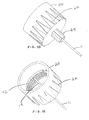
- Pen injection devices such as the exemplary drug delivery pen 10 as shown in Fig. 1 , provide the user a convenient way to carry a medicament supply. All of the required features and components for at least a single use are provided in the assembly, and in most cases, provide for multiple uses.
- the pen 10 typically comprises a dose knob/button 24, an outer sleeve 13, and a cap 21.
- the cap 21 covers a proximal end of the pen 10 and an injection needle attached thereto, and is used by the user to securely hold the drug delivery pen 10 in a shirt pocket, purse or other suitable location.
- the dose knob/button 24 allows a user to set the dosage of medication to be injected, and the outer sleeve 13 contains the driving mechanisms and supply, and further provides a gripping surface for the user to grip when injecting medication.
- Fig. 2A is an exploded view of the exemplary drug delivery pen 10 shown in Fig. 1 , and typical components contained therein.
- the dose knob/button 24 is provided and has a dual purpose.
- the dose knob/button 24 is used to both set the dosage of the medication to be injected and to inject the dosed medicament via the lead screw 7 and stopper 15 through the medicament cartridge 12, which is attached to the drug delivery pen through a lower housing 17.
- the dosing and delivery mechanisms are all found within the outer sleeve 13 and are not described in greater detail herein as they are understood by those knowledgeable of the prior art.
- the distal movement of the plunger or stopper 15 within the medicament cartridge 12 causes medication to be forced into the needle 11 of the hub 20.
- the medicament cartridge 12 is sealed by septum 16, which is punctured by a septum penetrating needle cannula 18 located within the hub 20.
- the hub 20 is preferably screwed onto the lower housing 17, although other attachment means can be used.
- Figs. 2B and 2C are perspective views of the pen needle of Fig. 2A in greater detail.
- the pen needle includes the hub 20 disposed at a non-patient end thereof which includes a plurality of ribs 64 for engagement with anti-rotation/retaining structures that will be described in greater detail below.
- protrusion 68 extends from a patient end of the hub 20 and the patient needle 11 extends from the protrusion 68.
- the septum-penetrating needle cannula 18 disposed within the non-patient end of the hub 20 fluidly communicates with the patient needle 11.
- the interior of the non-patient end of the hub 20 includes threads 72 for connection with the pen injector.
- Figs. 2A-2C illustrate one example of a pen needle.
- an outer cover 69 which attaches to the hub 20, covers the hub when not in use.
- An inner shield 59 covers the patient needle 11 within the outer cover 69.
- the inner shield 59 can be secured to the hub 20 to cover the patient needle 11 by any suitable means, such as an interference fit or a snap fit.
- the cap 21 fits snugly against outer sleeve 13 to allow a user to securely carry the drug delivery pen 10. At a time of use, the cap 21, outer cover 69 and inner shield 59 are removed to expose the hub 20.
- the medicament cartridge 12 is typically a tube sealed at one end with the septum 16 and sealed at the other end with the stopper 15.
- the septum 16 is pierceable by the septum penetrating cannula 18 in the hub 20, but does not move with respect to the medicament cartridge 12.
- the stopper 15 is axially displaceable within the medicament cartridge 12 to deliver the desired medicament amount while maintaining a fluid tight seal.
- a pen needle which includes the hub 20, needle 11, outer cover 69 and inner shield 59, is typically used for a single injection and is then disposed of.
- new pen needles are packaged individually and disposed loose in a container, such as a box or carton.
- Each pen needle is sealed in a package formed by the outer cover with a label covering the opening in the outer cover to identify the pen needle and provide a sterility barrier.
- containers of such packaged new pen needles do not include means for easily dispensing the new pen needles or containing used pen needles. Accordingly, a need exists for a storage assembly that easily dispenses new pen needles and stores both new and used pen needles.
- existing pen needle containers are configured to store a large number of packaged new pen needles.
- the large number of packaged new pen needles causes these containers to be large and bulky, such that the containers are not conducive to being carried by the user. Accordingly, a need exists for a storage assembly that is conveniently carried by a user.
- the above and other problems are substantially solved by providing a multi-pack assembly for containing and dispensing one or more new pen needles, and receiving and then safely and securely storing used pen needles after use.
- a housing in which a plurality of both new and used pen needles can be contained in a series of storage vessels.
- An exemplary embodiment of such a housing can be, but is not limited to, a row-like configuration in which each storage vessel is secured to adjacent storage vessels forming a row of aligned, storage vessel.
- the housing can provide caps for each individual pen needle storage vessel that can be opened independently of one another, and can be closed after use to prevent unwanted interaction with the pen needle contained therein.
- the housing can provide pen needle storage vessels that are held together in a row-like configuration by a solid segment, which gives a basic structure and shape to the overall needle assembly.
- the housing can be constructed of a frangible material and the row-like configuration of storage vessels can be scored, indented or perforated between vessels to allow a user to separate the storage vessels into smaller segments as desired.
- the housing can provide caps for each pen needle storage vessel having a barrel hinge, a living hinge, or combinations thereof.
- a multi-pack assembly for containing and then dispensing one or more new pen needles, and receiving and then safely and securely storing used pen needles, can be provided by a device including a plurality of pen needles individually contained in a plurality of pen needle storage vessels connected by a solid segment in a row-like configuration.
- a sterility barrier can be formed by individual caps that fit over each individual pen needle storage vessel, covering the non-patient end of the new pen needle.
- Each individual pen needle storage vessel can be opened independently of one another, and can be closed after use to prevent unwanted interaction with the pen needle contained therein.
- the pen needle storage vessels can be held together by the solid segment, which gives the basic structure and shape to the overall needle assembly.
- Fig. 1 is a perspective view of an assembled drug delivery pen for use with exemplary embodiments of the present invention
- Fig. 2A is an exploded perspective view of the components of the drug delivery pen of Fig. 1 ;
- Figs. 2B and 2C are perspective views of the pen needle for use with the drug delivery pen of Fig. 1 ;
- Fig. 3 is an enlarged perspective view of a pen needle containment device according to an exemplary embodiment of the present invention.
- Fig. 4 is an enlarged perspective view of the device of Fig. 3 illustrating a single opened cap according to an exemplary embodiment of the present invention
- Fig. 5 is an enlarged perspective view of the device of Fig. 3 illustrating a single opened cap and removed pen needle according to an exemplary embodiment of the present invention.
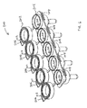
- Fig. 6 is an enlarged perspective view of another embodiment of a pen needle containment device with all caps opened according to an exemplary embodiment of the present invention.
- new pen needles are typically packaged individually and disposed loose in a container, such as a box or carton. Each pen needle is sealed in a package formed by the outer cover with a label covering the opening in the outer cover to identify the pen needle and provide a sterility barrier.
- containers of such packaged new pen needles do not include means for easily dispensing the new pen needles or containing used pen needles.
- existing pen needle containers are configured to store a large number of packaged new pen needles. The large number of packaged new pen needles causes these containers to be large and bulky, such that the containers are not conducive to being carried by the user.
- a multi-pack assembly for containing and dispensing new pen needles, and receiving and containing used pen needles is provided.
- the exemplary embodiments of the present invention consist of a plurality of pen needle storage vessels connected by a solid segment in a row-like configuration.
- a sterility barrier is formed by individual caps that fit over each individual pen needle storage vessel, covering the non-patient end of the new pen needle.
- the caps for each individual pen needle storage vessel can be opened independently of one another using for example, a living hinge, and can be closed after use to prevent unwanted interaction with the pen needle contained therein.
- the pen needle storage vessels are preferably held together by the solid segment, which gives the basic structure and shape to the overall assembly.
- the solid segment can be perforated, weakened or frangible in some manner between storage vessels to allow the user to tailor the number of connected storage vessels that are to be carried by breaking the solid segment at some point.
- FIG. 3 An exemplary housing 100 of a multi-pack assembly for containing and dispensing new pen needles, and receiving and containing used pen needles is shown in Fig. 3 .
- the housing 100 comprises a plurality of pen needle storage vessels 102-110 that can be connected by a solid, segment 142 in a row-like configuration.
- pen needle storage vessels 102-110 are shown, and are connected in a row-like configuration.
- any number of storage vessels can be provided, and arranged in any number of configurations.
- storage vessels 102 and 104 and hinges thereof are substantially the same and therefore, only storage vessel 102 will be described in further detail.
- Storage vessels 106-110 and hinges thereof are substantially the same and therefore, only storage vessel 110 will be described in detail.
- the storage vessels 102 and 110 illustrate a first and second exemplary embodiment of a hinge member 112 and 114, respectively, but are otherwise substantially the same.
- each of the storage vessels of the entire multi-pack assembly can comprise hinges 112, hinges 114, or any combination thereof.
- a cap 116 is provided which is rotatable about the hinge 112 for opening and closing a storage vessel body 118.
- the cap 116 is provided with a raised, substantially circular outer circumference 120 having a diameter and height sufficient to receive a similar raised, substantially circular outer circumference 122 of the vessel body 118.
- Each of the raised, substantially circular outer circumferences 120 and 122 are further provided with a chamfer 124 to aid in the rotatable engagement between the cap 116 and the vessel body 118.
- the cap 116 is also provided with a flexible securing member 128 opposite the hinge 112, and extending substantially perpendicular to the cap 116.
- the flexible securing member 128 is preferably molded or formed with the cap 116, and comprises an inclined detent 130 extending from an end of the flexible member 128.
- the inclined detent 130 comprises an inclined surface and a shoulder to secure the cap 116 to the vessel body 118.
- the flexible member 128 and inclined detent 130 are configured to engage a flat portion 132 of the vessel body 118 and be deflected away from the flat portion 132 when the cap 116 is being closed.
- the flexible member 128 and inclined detent 130 are elastically urged to return to a non-deflected position such that that the shoulder of the inclined detent 130 captures and releasably secures a shoulder of the flat portion 132.
- the inclined detent 130 of the flexible member 128 is configured to extend slightly past the flat portion 132, thereby providing user access to the extended portion to aid in user deflection of the inclined detent 130 from the secured position to thereby open the cap 116.
- each cap is rotatably secured to the vessel bodies via flexible member, hinge, or other similar element.
- the cap 116 is rotatably secured to the vessel body 118 via an exemplary barrel hinge 112 and can be easily rotated between open and closed positions.
- a hinge 112 can be used in exemplary embodiments wherein the cap 116 is preferred to remain open or in position upon release.
- the exemplary cap 134 of storage vessel 110 is secured to the vessel body via an exemplary living hinge 114.
- the living hinge 114 can comprise a thin flexible piece to join the more rigid cap 134 to the storage vessel 110.
- Such a hinge 114 can be used in exemplary embodiments wherein the cap 134 is preferred to return to a position upon release.
- each of the storage vessels of the entire multi-pack assembly can comprise hinges 112, hinges 114, or any combination thereof.
- a living hinge is typically a thin flexible member that joins two rigid parts together, allowing then to bend along the line of the hinge with minimal friction and wear.
- Such hinges can be manufactured in an injection molding operation that creates all three parts at one time as a single unit, which can remain functional over the life of the hinge.
- Polyethylene and polypropylene are typically used for living hinges, due to their fatigue resistance.
- Each storage vessel comprises an opening configured to store both new and used pen needles and is provided with an inner diameter sufficient to releasably secure the new and used pen needle and prevent rotation of the pen needle therein to aid in attachment and removal of the pen needle and the pen device.
- the vessel body of each such as vessel body 118, comprises an opening 136 configured to releasably secure a hub 20 of a pen needle.
- the vessel body further comprises a reduced diameter portion 138 to releasably secure one or more of a hub portion and a pen needle 11.
- the vessel body further comprises a closed end 140 thereof with rounded features to aid in storage by a user.
- Each vessel body of storage vessels is arranged and secured via a substantially flat, securing band 142 which is provided to secure each of the pen needle storage vessels 102-110 in a row-like configuration.
- the pen needle storage vessels can be arranged and secured in a staggered row-like configuration, a double or multiple stacked row-like configuration, and/or in a manner wherein each pen needle storage vessel faces the same direction or faces opposite directions.
- the securing band 142 comprises a substantially flat member molded or constructed of the same material as the storage vessels, and which gives the basic structure and shape to the overall needle storage assembly.
- the solid segment 142 can be perforated, weakened or frangible in some manner to allow the user to tailor the number of connected storage vessels that are to be carried by breaking the solid segment 142 at some point.
- Fig. 5 is a perspective view of the device of Fig. 3 illustrating a single opened cap and removed pen needle according to an exemplary embodiment of the present invention.
- the new pen needle has been removed from the housing 100 for use, by engagement with a drug delivery pen 10 of Fig. 2A .
- the drug delivery pen 10 can be threaded to, or otherwise secured to the new pen needle for removal from the housing.
- An inner shield may not be required in each case, as the reduced diameter portion 138 can be configured to releasably secure the protrusion 68 from which the patient needle 11 extends.
- the user can then simply return the used pen needle to the housing 100 and more specifically, to the empty vessel 118 for storage.
- the vessel 118 can also provide features to prevent rotation of the pen needle when positioned in the vessel such that the user can simply unscrew or otherwise release the pen needle from the drug delivery pen and close the cap 116 for storage.
- the caps for each individual pen needle storage vessel can be opened independently of one another, and can be closed after use to prevent unwanted interaction with the pen needle contained therein.
- the pen needle storage vessels are held together by the solid segment, which gives the basic structure and shape to the overall needle assembly.
- Fig. 6 is a perspective view of another embodiment of a pen needle containment housing 200 with all caps opened according to an exemplary embodiment of the present invention.
- each cap is secured to each respective storage vessel, and can be opened and closed individually to cover the storage vessels 204 substantially as described above in regard to Figs. 3-5 .
- Such an arrangement can further allow the use of alternate closing elements, such as the tabs 206 and slotted members 208.
- multiple tabs 206 and slotted members 208 are shown, which can be engaged during closure of the caps.
- the tabs 206 can be deflected into each opening 208, respectively, to capture the tabs in the openings.
- the tabs can be easily deflected by the user to permit release of the tabs from the openings to open the caps.
- a detent or expanded portion 212 can be provided at an end of each tab 206 to secure the tabs within the openings when inserted therein.
- the remaining features of the pen needle containment housing 200 are substantially the same as described above in regard to the pen needle containment housing 100.
- a protrusion or other feature 210 is provided as anti-rotation and/or general friction projections to secure the pen needles and/or hubs thereof in each opening.
- the protrusion 210 releasably secures the pen needle or hub in the opening to prevent the pen needle from simply falling from an open vessel, and to secure the pen needle to allow the threaded engagement or disengagement with the drug delivery pen 10, such as when a new pen needle is being withdrawn and when a used pen needle is being returned for storage.
- the protrusion 210 can comprise a detent disposed upon an inner wall of the opening of the storage vessel to work in conjunction with the hub of a pen needle to prevent rotation of the pen needle when the pen needle is in a dispensing position.
- the anti-rotation/retaining features 210 prevent the pen needle from rotating and permit the user to connect a pen injector or a medicament cartridge to the hub by threading the pen injector or medicament cartridge into the threads 72 of the hub 20. While preventing rotation of the pen needle during connection to the pen injector, subsequent to the connection, the fit between the anti-rotation/retaining features 210 and the pen needle permits the user to axially withdraw the combined pen injector and pen needle from the storage vessel.
- the user when returning the used pen needle to the storage vessel, the user axially inserts the pen needle into the storage vessel to engage the ribs 64 of the hub 20 with the anti-rotation/retaining features 210. Subsequent to the engagement, the user rotates the pen injector to unthread the pen injector from the threads 72 of the hub 20, thereby disengaging the pen injector from the pen needle.
- the fit between the anti-rotation/retaining features 210 and the pen needle provides some resistance to removal of the pen needle from the storage vessel and prevents the pen needle from simply falling out of the storage vessel.
- a single cover (not shown) can be provided that can snap on and off of the entire assembly to cover the cavities therein.
- each individual cover or single cover can be provided in a tongue-and-groove or dovetailed manner such that the cover(s) can slide on and off to cover the cavities therein.
- a detent or other friction can be provided to hold the sliding covers in one or more positions.
- a sterility barrier is formed by the individual caps that fit over each storage vessel, covering the non-patient end of the new pen needle contained therein.
- the caps can be sealed to the storage vessel in some manner prior to a first opening, or the presence of the closed cap can provide sterility of each new pen needle via tortuous path.
- covers and/or seals can be used in combination with the caps to enhance protection.
- a cover such as a paper, foil, or plastic label can also be used as the primary or sole sterility barrier for each individual new pen needle.
- a separate piece can be used to cover the non-patient ends of the returned needles, such as a slide that can be moved out of the way to access new pen needles.
- a system and method can be provided to distinguish new from used pen needles or the storage thereof.
- a paper tape can be provided on the top of the covers. Once a cover is opened, the opening breaks part of the tape, thereby indicating that the cap has been opened and showing that the needle therein has been removed or has been used.
- Pen needles of the exemplary embodiments can be manufactured using existing processes and subsequently assembled into the housings of the exemplary embodiments of the present invention, thereby simplifying the manufacturing process.
- the overall size of the exemplary embodiments of the present invention is minimized by allowing used pen needles to be stored in substantially the same spaces previously used to store the new needles.
- the exemplary embodiments of the present invention can be constructed having a size and shape, and contoured edges, to increase the comfort of the user during transportation, such as in a user's pocket.
- Figs. 2B and 2C are perspective views of the pen needle of Fig. 2A wherein the pen needle includes the hub 20, protrusion 68 and patient needle 11.
- the septum-penetrating needle cannula 18 disposed within the non-patient end of the hub 20 fluidly communicates with the patient needle 11, and the interior of the non-patient end of the hub 20 includes threads or other features 72 for connection with the pen injector.
- the pen needle can omit one or more of the above features as long as sterility of both the patient and non-patient ends of the cannula is maintained.
- an exemplary pen needle can also be provided having a hub and cannula assembly only.
- the multi-pack assembly housings 100 and 200, and hinges thereof including the living hinge can be constructed of one or more of a polycarbonate, polyethylene, polypropylene and acrylonitrile butadiene styrene material, but are not limited thereto. Further, the multi-pack assembly housings 100 and 200 and/or caps thereof can be color-coded to simplify identification of the new pen needles stored therein.
- a lockout system and method can be provided such that after the use of the final needle, the user can manually lock the multi-pack assembly housings 100 and 200 (i.e., manually lock the multi-pack assembly housings closed) to allow for safe disposal.
- a manual lock can be provided on the needle storage assembly, thereby allowing the user to manually lock the storage assembly after final use to allow for safe disposal thereof.
- the latches described above can be configured to prevent re-opening by the user once fully closed.
- the latches of 128-132 and 206-208 can be configured to irreversibly lock once fully closed to prevent opening and re-use of a non-new pen needle.
- an emergency needle feature can be provided wherein at least one new or used needle can remain accessible, such that the user has access to the at least one of the new or used needles for use in case of an emergency.
- only one needle can be provided as always accessible, thereby providing an available needle for use in case of emergency.
- the other pen needles can be locked into the storage assembly and can no longer be accessible.
Abstract
Description
- This application claims the benefit under 35 U.S.C. §119(e) of a U.S. provisional patent application of David Chapin et al. entitled "Living Hinge Needle Assembly For Medicament Delivery Device", Serial No.
61/344,537, filed on August 16, 2010 13/204,615, filed on August 5, 2011 - The present invention relates to a storage assembly for pen needles of an injection apparatus. More particularly, the present invention relates to a storage assembly for storing both new and used pen needles of an injection apparatus.
- In certain circumstances, it is desirable to inject medication directly into human tissue. Typically, syringes or pen injection devices are used to inject medicaments into tissue areas, such as the intramuscular tissue layer, the subcutaneous tissue layer, and the intradermal tissue layer. The assembly and operation of such a pen injection device is described in
U.S. Patent No. 7,645,264, issued on January 12, 2010 , the entire contents of which are incorporated herein by reference. - Pen injection devices, such as the exemplary
drug delivery pen 10 as shown inFig. 1 , provide the user a convenient way to carry a medicament supply. All of the required features and components for at least a single use are provided in the assembly, and in most cases, provide for multiple uses. To do so, thepen 10 typically comprises a dose knob/button 24, anouter sleeve 13, and acap 21. Thecap 21 covers a proximal end of thepen 10 and an injection needle attached thereto, and is used by the user to securely hold thedrug delivery pen 10 in a shirt pocket, purse or other suitable location. The dose knob/button 24 allows a user to set the dosage of medication to be injected, and theouter sleeve 13 contains the driving mechanisms and supply, and further provides a gripping surface for the user to grip when injecting medication. -
Fig. 2A is an exploded view of the exemplarydrug delivery pen 10 shown inFig. 1 , and typical components contained therein. At a distal end, the dose knob/button 24 is provided and has a dual purpose. The dose knob/button 24 is used to both set the dosage of the medication to be injected and to inject the dosed medicament via thelead screw 7 and stopper 15 through themedicament cartridge 12, which is attached to the drug delivery pen through alower housing 17. In standard drug delivery pens, the dosing and delivery mechanisms are all found within theouter sleeve 13 and are not described in greater detail herein as they are understood by those knowledgeable of the prior art. The distal movement of the plunger or stopper 15 within themedicament cartridge 12 causes medication to be forced into theneedle 11 of thehub 20. Themedicament cartridge 12 is sealed byseptum 16, which is punctured by a septum penetratingneedle cannula 18 located within thehub 20. Thehub 20 is preferably screwed onto thelower housing 17, although other attachment means can be used. -
Figs. 2B and 2C are perspective views of the pen needle ofFig. 2A in greater detail. As shown inFig. 2B , the pen needle includes thehub 20 disposed at a non-patient end thereof which includes a plurality ofribs 64 for engagement with anti-rotation/retaining structures that will be described in greater detail below. In addition,protrusion 68 extends from a patient end of thehub 20 and thepatient needle 11 extends from theprotrusion 68. The septum-penetratingneedle cannula 18 disposed within the non-patient end of thehub 20 fluidly communicates with thepatient needle 11. Further, as shown inFig. 2C , the interior of the non-patient end of thehub 20 includesthreads 72 for connection with the pen injector.Figs. 2A-2C illustrate one example of a pen needle. - To protect a user, or anyone who handles the
drug delivery pen 10, anouter cover 69, which attaches to thehub 20, covers the hub when not in use. Aninner shield 59 covers thepatient needle 11 within theouter cover 69. Theinner shield 59 can be secured to thehub 20 to cover thepatient needle 11 by any suitable means, such as an interference fit or a snap fit. Thecap 21 fits snugly againstouter sleeve 13 to allow a user to securely carry thedrug delivery pen 10. At a time of use, thecap 21,outer cover 69 andinner shield 59 are removed to expose thehub 20. - The
medicament cartridge 12 is typically a tube sealed at one end with theseptum 16 and sealed at the other end with thestopper 15. Theseptum 16 is pierceable by theseptum penetrating cannula 18 in thehub 20, but does not move with respect to themedicament cartridge 12. Thestopper 15 is axially displaceable within themedicament cartridge 12 to deliver the desired medicament amount while maintaining a fluid tight seal. - A pen needle, which includes the
hub 20,needle 11,outer cover 69 andinner shield 59, is typically used for a single injection and is then disposed of. Typically, new pen needles are packaged individually and disposed loose in a container, such as a box or carton. Each pen needle is sealed in a package formed by the outer cover with a label covering the opening in the outer cover to identify the pen needle and provide a sterility barrier. However, containers of such packaged new pen needles do not include means for easily dispensing the new pen needles or containing used pen needles. Accordingly, a need exists for a storage assembly that easily dispenses new pen needles and stores both new and used pen needles. - Additionally, existing pen needle containers are configured to store a large number of packaged new pen needles. The large number of packaged new pen needles causes these containers to be large and bulky, such that the containers are not conducive to being carried by the user. Accordingly, a need exists for a storage assembly that is conveniently carried by a user.
- In accordance with aspects of exemplary embodiments of the present invention, the above and other problems are substantially solved by providing a multi-pack assembly for containing and dispensing one or more new pen needles, and receiving and then safely and securely storing used pen needles after use.
- In accordance with an aspect of the present invention, a housing is provided in which a plurality of both new and used pen needles can be contained in a series of storage vessels. An exemplary embodiment of such a housing can be, but is not limited to, a row-like configuration in which each storage vessel is secured to adjacent storage vessels forming a row of aligned, storage vessel.
- In accordance with another aspect of the present invention, the housing can provide caps for each individual pen needle storage vessel that can be opened independently of one another, and can be closed after use to prevent unwanted interaction with the pen needle contained therein.
- In accordance with another aspect of the present invention, the housing can provide pen needle storage vessels that are held together in a row-like configuration by a solid segment, which gives a basic structure and shape to the overall needle assembly.
- In accordance with another aspect of the present invention, the housing can be constructed of a frangible material and the row-like configuration of storage vessels can be scored, indented or perforated between vessels to allow a user to separate the storage vessels into smaller segments as desired.
- In accordance with another aspect of the present invention, the housing can provide caps for each pen needle storage vessel having a barrel hinge, a living hinge, or combinations thereof.
- In accordance with another aspect of the present invention, a multi-pack assembly for containing and then dispensing one or more new pen needles, and receiving and then safely and securely storing used pen needles, can be provided by a device including a plurality of pen needles individually contained in a plurality of pen needle storage vessels connected by a solid segment in a row-like configuration. A sterility barrier can be formed by individual caps that fit over each individual pen needle storage vessel, covering the non-patient end of the new pen needle. Each individual pen needle storage vessel can be opened independently of one another, and can be closed after use to prevent unwanted interaction with the pen needle contained therein. The pen needle storage vessels can be held together by the solid segment, which gives the basic structure and shape to the overall needle assembly.
- Objects, advantages, and salient features of the invention will become apparent from the following detailed description, which, taken in conjunction with the annexed drawings, discloses exemplary embodiments of the invention.
- The above benefits and other advantages of the various embodiments of the present invention will be more apparent from the following detailed description of exemplary embodiments of the present invention and from the accompanying figures, in which:
-
Fig. 1 is a perspective view of an assembled drug delivery pen for use with exemplary embodiments of the present invention; -
Fig. 2A is an exploded perspective view of the components of the drug delivery pen ofFig. 1 ; -
Figs. 2B and 2C are perspective views of the pen needle for use with the drug delivery pen ofFig. 1 ; -
Fig. 3 is an enlarged perspective view of a pen needle containment device according to an exemplary embodiment of the present invention; -
Fig. 4 is an enlarged perspective view of the device ofFig. 3 illustrating a single opened cap according to an exemplary embodiment of the present invention; -
Fig. 5 is an enlarged perspective view of the device ofFig. 3 illustrating a single opened cap and removed pen needle according to an exemplary embodiment of the present invention; and -
Fig. 6 is an enlarged perspective view of another embodiment of a pen needle containment device with all caps opened according to an exemplary embodiment of the present invention. - Throughout the drawings, like reference numbers will be understood to refer to like parts, components and structures.
- As noted above, new pen needles are typically packaged individually and disposed loose in a container, such as a box or carton. Each pen needle is sealed in a package formed by the outer cover with a label covering the opening in the outer cover to identify the pen needle and provide a sterility barrier. However, containers of such packaged new pen needles do not include means for easily dispensing the new pen needles or containing used pen needles. Additionally, existing pen needle containers are configured to store a large number of packaged new pen needles. The large number of packaged new pen needles causes these containers to be large and bulky, such that the containers are not conducive to being carried by the user.
- Current pen needles are sold individually packaged inside a plastic cover, with a label adhered to the cover to identify the needle and provide a sterility barrier. However, a more convenient system and method is desired including a multiple needle package configuration that stores and provides new pen needles for use, and includes some provision for receiving and containing used pen needles after use. The exemplary embodiments of the present invention address these and other needs by providing a multi-pack assembly including multiple new pen needles in user accessible openings of the assembly, wherein covers or other enclosures are provided or positioned to enclose each new pen needle inside the user accessible openings of the assembly.
- In a first exemplary embodiment of the present invention as shown in
Figs. 3-5 , and a second exemplary embodiment of the present invention as shown inFig. 6 , a multi-pack assembly for containing and dispensing new pen needles, and receiving and containing used pen needles is provided. The exemplary embodiments of the present invention consist of a plurality of pen needle storage vessels connected by a solid segment in a row-like configuration. A sterility barrier is formed by individual caps that fit over each individual pen needle storage vessel, covering the non-patient end of the new pen needle. In an exemplary embodiment of the present invention, the caps for each individual pen needle storage vessel can be opened independently of one another using for example, a living hinge, and can be closed after use to prevent unwanted interaction with the pen needle contained therein. The pen needle storage vessels are preferably held together by the solid segment, which gives the basic structure and shape to the overall assembly. In yet other embodiments of the present invention, the solid segment can be perforated, weakened or frangible in some manner between storage vessels to allow the user to tailor the number of connected storage vessels that are to be carried by breaking the solid segment at some point. - An
exemplary housing 100 of a multi-pack assembly for containing and dispensing new pen needles, and receiving and containing used pen needles is shown inFig. 3 . In a first exemplary embodiment of the present invention, thehousing 100 comprises a plurality of pen needle storage vessels 102-110 that can be connected by a solid,segment 142 in a row-like configuration. In the exemplary embodiment shown inFig. 3 , five pen needle storage vessels 102-110 are shown, and are connected in a row-like configuration. However, in yet other embodiments of the present invention, any number of storage vessels can be provided, and arranged in any number of configurations. - In the exemplary embodiment,
storage vessels storage vessel 102 will be described in further detail. Storage vessels 106-110 and hinges thereof are substantially the same and therefore, onlystorage vessel 110 will be described in detail. Thestorage vessels hinge member - In a first
exemplary storage vessel 102, acap 116 is provided which is rotatable about thehinge 112 for opening and closing astorage vessel body 118. Thecap 116 is provided with a raised, substantially circularouter circumference 120 having a diameter and height sufficient to receive a similar raised, substantially circularouter circumference 122 of thevessel body 118. Each of the raised, substantially circularouter circumferences chamfer 124 to aid in the rotatable engagement between thecap 116 and thevessel body 118. - The
cap 116 is also provided with aflexible securing member 128 opposite thehinge 112, and extending substantially perpendicular to thecap 116. Theflexible securing member 128 is preferably molded or formed with thecap 116, and comprises aninclined detent 130 extending from an end of theflexible member 128. Theinclined detent 130 comprises an inclined surface and a shoulder to secure thecap 116 to thevessel body 118. Specifically, theflexible member 128 andinclined detent 130 are configured to engage aflat portion 132 of thevessel body 118 and be deflected away from theflat portion 132 when thecap 116 is being closed. At a completely closed position, theflexible member 128 andinclined detent 130 are elastically urged to return to a non-deflected position such that that the shoulder of theinclined detent 130 captures and releasably secures a shoulder of theflat portion 132. Further, theinclined detent 130 of theflexible member 128 is configured to extend slightly past theflat portion 132, thereby providing user access to the extended portion to aid in user deflection of theinclined detent 130 from the secured position to thereby open thecap 116. - Each cap is rotatably secured to the vessel bodies via flexible member, hinge, or other similar element. In a first exemplary embodiment, the
cap 116 is rotatably secured to thevessel body 118 via anexemplary barrel hinge 112 and can be easily rotated between open and closed positions. Such ahinge 112 can be used in exemplary embodiments wherein thecap 116 is preferred to remain open or in position upon release. Theexemplary cap 134 ofstorage vessel 110 is secured to the vessel body via anexemplary living hinge 114. The livinghinge 114 can comprise a thin flexible piece to join the morerigid cap 134 to thestorage vessel 110. Such ahinge 114 can be used in exemplary embodiments wherein thecap 134 is preferred to return to a position upon release. In yet other embodiments of the present invention, each of the storage vessels of the entire multi-pack assembly can comprise hinges 112, hinges 114, or any combination thereof. - As known to those skilled in the art, a living hinge is typically a thin flexible member that joins two rigid parts together, allowing then to bend along the line of the hinge with minimal friction and wear. Such hinges can be manufactured in an injection molding operation that creates all three parts at one time as a single unit, which can remain functional over the life of the hinge. Polyethylene and polypropylene are typically used for living hinges, due to their fatigue resistance.
- Each storage vessel comprises an opening configured to store both new and used pen needles and is provided with an inner diameter sufficient to releasably secure the new and used pen needle and prevent rotation of the pen needle therein to aid in attachment and removal of the pen needle and the pen device. To do so, the vessel body of each, such as
vessel body 118, comprises anopening 136 configured to releasably secure ahub 20 of a pen needle. The vessel body further comprises a reduceddiameter portion 138 to releasably secure one or more of a hub portion and apen needle 11. Finally, the vessel body further comprises aclosed end 140 thereof with rounded features to aid in storage by a user. - Each vessel body of storage vessels is arranged and secured via a substantially flat, securing
band 142 which is provided to secure each of the pen needle storage vessels 102-110 in a row-like configuration. Although a row-like configuration is shown, in yet other exemplary embodiments of the present invention, the pen needle storage vessels can be arranged and secured in a staggered row-like configuration, a double or multiple stacked row-like configuration, and/or in a manner wherein each pen needle storage vessel faces the same direction or faces opposite directions. In an exemplary embodiment, the securingband 142 comprises a substantially flat member molded or constructed of the same material as the storage vessels, and which gives the basic structure and shape to the overall needle storage assembly. In yet other embodiments of the present invention, thesolid segment 142 can be perforated, weakened or frangible in some manner to allow the user to tailor the number of connected storage vessels that are to be carried by breaking thesolid segment 142 at some point. -
Fig. 5 is a perspective view of the device ofFig. 3 illustrating a single opened cap and removed pen needle according to an exemplary embodiment of the present invention. As shown inFig. 5 , the new pen needle has been removed from thehousing 100 for use, by engagement with adrug delivery pen 10 ofFig. 2A . Thedrug delivery pen 10 can be threaded to, or otherwise secured to the new pen needle for removal from the housing. An inner shield may not be required in each case, as the reduceddiameter portion 138 can be configured to releasably secure theprotrusion 68 from which thepatient needle 11 extends. Upon completion, the user can then simply return the used pen needle to thehousing 100 and more specifically, to theempty vessel 118 for storage. As noted above, thevessel 118 can also provide features to prevent rotation of the pen needle when positioned in the vessel such that the user can simply unscrew or otherwise release the pen needle from the drug delivery pen and close thecap 116 for storage. - In an exemplary embodiment of the present invention, the caps for each individual pen needle storage vessel can be opened independently of one another, and can be closed after use to prevent unwanted interaction with the pen needle contained therein. The pen needle storage vessels are held together by the solid segment, which gives the basic structure and shape to the overall needle assembly.
Fig. 6 is a perspective view of another embodiment of a penneedle containment housing 200 with all caps opened according to an exemplary embodiment of the present invention. - In the exemplary embodiment shown in
Fig. 6 , another exemplarycap assembly embodiment 202 is shown wherein each cap is secured to each respective storage vessel, and can be opened and closed individually to cover thestorage vessels 204 substantially as described above in regard toFigs. 3-5 . Such an arrangement can further allow the use of alternate closing elements, such as thetabs 206 and slottedmembers 208. In the exemplary embodiment shown,multiple tabs 206 and slottedmembers 208 are shown, which can be engaged during closure of the caps. In the exemplary embodiment shown, thetabs 206 can be deflected into eachopening 208, respectively, to capture the tabs in the openings. The tabs can be easily deflected by the user to permit release of the tabs from the openings to open the caps. A detent or expandedportion 212 can be provided at an end of eachtab 206 to secure the tabs within the openings when inserted therein. The remaining features of the penneedle containment housing 200 are substantially the same as described above in regard to the penneedle containment housing 100. - In each of the
storage vessels 204, a protrusion orother feature 210 is provided as anti-rotation and/or general friction projections to secure the pen needles and/or hubs thereof in each opening. In doing so, theprotrusion 210 releasably secures the pen needle or hub in the opening to prevent the pen needle from simply falling from an open vessel, and to secure the pen needle to allow the threaded engagement or disengagement with thedrug delivery pen 10, such as when a new pen needle is being withdrawn and when a used pen needle is being returned for storage. Theprotrusion 210 can comprise a detent disposed upon an inner wall of the opening of the storage vessel to work in conjunction with the hub of a pen needle to prevent rotation of the pen needle when the pen needle is in a dispensing position. For example, when the pen needle is in the dispensing position within the storage vessel and the anti-rotation/retainng features 210 are engaged with the ribs 64 (seeFigs. 2B and 2C ) ofhub 20, the anti-rotation/retaining features 210 prevent the pen needle from rotating and permit the user to connect a pen injector or a medicament cartridge to the hub by threading the pen injector or medicament cartridge into thethreads 72 of thehub 20. While preventing rotation of the pen needle during connection to the pen injector, subsequent to the connection, the fit between the anti-rotation/retaining features 210 and the pen needle permits the user to axially withdraw the combined pen injector and pen needle from the storage vessel. - Conversely, when returning the used pen needle to the storage vessel, the user axially inserts the pen needle into the storage vessel to engage the
ribs 64 of thehub 20 with the anti-rotation/retaining features 210. Subsequent to the engagement, the user rotates the pen injector to unthread the pen injector from thethreads 72 of thehub 20, thereby disengaging the pen injector from the pen needle. The fit between the anti-rotation/retaining features 210 and the pen needle provides some resistance to removal of the pen needle from the storage vessel and prevents the pen needle from simply falling out of the storage vessel. - Further, in yet other exemplary embodiments of the present invention, a single cover (not shown) can be provided that can snap on and off of the entire assembly to cover the cavities therein. In still other exemplary embodiments of the present invention, each individual cover or single cover can be provided in a tongue-and-groove or dovetailed manner such that the cover(s) can slide on and off to cover the cavities therein. A detent or other friction can be provided to hold the sliding covers in one or more positions.
- In each of the exemplary embodiments described above, a sterility barrier is formed by the individual caps that fit over each storage vessel, covering the non-patient end of the new pen needle contained therein. The caps can be sealed to the storage vessel in some manner prior to a first opening, or the presence of the closed cap can provide sterility of each new pen needle via tortuous path. However, covers and/or seals can be used in combination with the caps to enhance protection. For example, a cover (not shown), such as a paper, foil, or plastic label can also be used as the primary or sole sterility barrier for each individual new pen needle. In such an embodiment, in order to cover the used pen needles, a separate piece can be used to cover the non-patient ends of the returned needles, such as a slide that can be moved out of the way to access new pen needles.
- Further, in these or other exemplary embodiments of the present invention, a system and method can be provided to distinguish new from used pen needles or the storage thereof. For example, in one embodiment, a paper tape can be provided on the top of the covers. Once a cover is opened, the opening breaks part of the tape, thereby indicating that the cap has been opened and showing that the needle therein has been removed or has been used.
- Pen needles of the exemplary embodiments can be manufactured using existing processes and subsequently assembled into the housings of the exemplary embodiments of the present invention, thereby simplifying the manufacturing process. The overall size of the exemplary embodiments of the present invention is minimized by allowing used pen needles to be stored in substantially the same spaces previously used to store the new needles. Further, the exemplary embodiments of the present invention can be constructed having a size and shape, and contoured edges, to increase the comfort of the user during transportation, such as in a user's pocket.
- As noted above,
Figs. 2B and 2C are perspective views of the pen needle ofFig. 2A wherein the pen needle includes thehub 20,protrusion 68 andpatient needle 11. The septum-penetratingneedle cannula 18 disposed within the non-patient end of thehub 20 fluidly communicates with thepatient needle 11, and the interior of the non-patient end of thehub 20 includes threads orother features 72 for connection with the pen injector. In these or other exemplary embodiments of the present invention the pen needle can omit one or more of the above features as long as sterility of both the patient and non-patient ends of the cannula is maintained. For example, an exemplary pen needle can also be provided having a hub and cannula assembly only. - In the exemplary embodiments of the present invention, the
multi-pack assembly housings multi-pack assembly housings - Further, in these or other exemplary embodiments of the present invention, a lockout system and method can be provided such that after the use of the final needle, the user can manually lock the
multi-pack assembly housings 100 and 200 (i.e., manually lock the multi-pack assembly housings closed) to allow for safe disposal. For example, a manual lock can be provided on the needle storage assembly, thereby allowing the user to manually lock the storage assembly after final use to allow for safe disposal thereof. To do so, the latches described above can be configured to prevent re-opening by the user once fully closed. The latches of 128-132 and 206-208 can be configured to irreversibly lock once fully closed to prevent opening and re-use of a non-new pen needle. - However, in these and other exemplary embodiments of the present invention, an emergency needle feature can be provided wherein at least one new or used needle can remain accessible, such that the user has access to the at least one of the new or used needles for use in case of an emergency. Alternatively, in yet other embodiments of the present invention, only one needle can be provided as always accessible, thereby providing an available needle for use in case of emergency. The other pen needles can be locked into the storage assembly and can no longer be accessible.
- The foregoing embodiments and advantages are merely exemplary and are not to be construed as limiting the scope of the present invention. Various modifications, alternatives and variations will be apparent to those of ordinary skill in the art, and are intended to fall within the scope of the invention as defined in the appended claims and their equivalents.
Claims (15)
- An assembly for storing both new and used pen needles of an injection apparatus, comprising:a housing, comprising a plurality of storage vessels, wherein each of said storage vessels is secured to an adjacent storage vessel and comprises an enlarged open proximal end and a closed distal end; anda cap for each individual storage vessel, wherein each cap comprises an opening to releasably receive said enlarged open proximal end of said storage vessels
- The assembly for storing both new and used pen needles of an injection apparatus as recited in claim 1, further comprising a segment securing each of said storage vessels to adjacent storage vessels.
- The assembly for storing both new and used pen needles of an injection apparatus as recited in claim 1, wherein said housing is frangible between said storage vessels to allow separation.
- The assembly for storing both new and used pen needles of an injection apparatus as recited in claim 1, further comprising a hinge between said cap and said housing, wherein said hinge comprises one of a barrel hinge, a living hinge, or combination thereof.
- The assembly for storing both new and used pen needles of an injection apparatus as recited in claim 4, wherein said housing, said caps and said hinge is molded as a single piece.
- The assembly for storing both new and used pen needles of an injection apparatus as recited in claim 1, wherein said enlarged open proximal end of said storage vessels comprise one or more detents for holding a pen needle in said storage vessel and preventing rotation of said pen needle, and wherein said closed distal end of said storage vessel is configured to releasable secure a distal end of said pen needle.
- The assembly for storing both new and used pen needles of an injection apparatus as recited in claim 1, wherein said caps form sterility barriers for each individual pen needle storage vessel.
- The assembly for storing both new and used pen needles of an injection apparatus as recited in claim 1, wherein:said storage vessels can be arranged in a staggered row-like configuration, a double or multiple stacked row-like configuration, or in a manner wherein each storage vessel faces the same direction or faces opposite directions.
- An assembly for storing both new and used pen needles of an injection apparatus, comprising:a plurality of storage vessels, wherein each of said storage vessels is secured to an adjacent storage vessel and comprises an enlarged open proximal end and a closed distal end;a segment securing each of said storage vessels to an adjacent storage vessel; anda cap for each individual storage vessel, wherein each cap comprises an opening to releasably receive said enlarged open proximal end of said storage vessel, and a living hinge between said cap and said segment, wherein said storage vessels, segment, caps and living hinge are molded as a single piece.
- The assembly for storing both new and used pen needles of an injection apparatus as recited in claims 1 or 9, further comprising a flexible securing member extending substantially perpendicular to said cap, said flexible securing member comprising an inclined detent extending from an end of said flexible securing member to releasably secure said cap to said storage vessel.
- The assembly for storing both new and used pen needles of an injection apparatus as recited in claims 2 or 9, further comprising:a flexible securing member extending from said cap;wherein said segment comprises a receiving opening for each of said securing members, respectively, to releasably secure said cap to said storage vessel.
- The assembly for storing both new and used pen needles of an injection apparatus as recited in claims 2 or 9, further comprising:a flexible securing member extending from said cap, andwherein said segment comprises a receiving opening for each of said securing members, respectively, to irreversibly secure said caps to said storage vessels.
- A method for storing both new and used pen needles of an injection apparatus in a storage assembly, comprising the steps of:releasing a flexible securing member to rotatably open a cap of a storage vessel via a hinge to break a sterile barrier provided by said cap and access a new pen needle secured within an opening of said storage vessel, wherein said storage vessel is secured to a plurality of adjacent storage vessels;attaching said new pen needle to a drug delivery pen, wherein said new pen needle is releasably secured within said opening of said storage vessel and prevented from rotating; andpulling said new pen needle from said opening of said storage vessel.
- The method for storing both new and used pen needles of an injection apparatus in a storage assembly as recited in claim 13, further comprising the steps of:inserting said used pen needle into said opening of said storage vessel, engaging said anti-rotation feature, and unscrewing said pen injection device from said used pen needle and leaving said used pen needle in said opening of said storage vessel; andclosing said cap of said storage vessel via said living hinge and securing said flexible securing member to said storage vessel for storage of said used pen needle.
- The method for storing both new and used pen needles of an injection apparatus in a storage assembly as recited in claim 13, further comprising the step of irreversibly locking said cap of said storage vessel to create a sharps container.
Applications Claiming Priority (2)
| Application Number | Priority Date | Filing Date | Title |
|---|---|---|---|
| US34453710P | 2010-08-16 | 2010-08-16 | |
| US13/204,615 US8887912B2 (en) | 2010-08-16 | 2011-08-05 | Living hinge needle assembly for medicament delivery device |
Publications (3)
| Publication Number | Publication Date |
|---|---|
| EP2420268A2 true EP2420268A2 (en) | 2012-02-22 |
| EP2420268A3 EP2420268A3 (en) | 2012-05-02 |
| EP2420268B1 EP2420268B1 (en) | 2018-11-28 |
Family
ID=44651122
Family Applications (1)
| Application Number | Title | Priority Date | Filing Date |
|---|---|---|---|
| EP11177453.5A Active EP2420268B1 (en) | 2010-08-16 | 2011-08-12 | Needle assembly storage magazine |
Country Status (5)
| Country | Link |
|---|---|
| US (2) | US8887912B2 (en) |
| EP (1) | EP2420268B1 (en) |
| JP (1) | JP6001244B2 (en) |
| CA (1) | CA2748885C (en) |
| ES (1) | ES2712962T3 (en) |
Cited By (1)
| Publication number | Priority date | Publication date | Assignee | Title |
|---|---|---|---|---|
| WO2020120086A1 (en) * | 2018-12-13 | 2020-06-18 | Shl Medical Ag | Arrangement for supporting medicament delivery devices and system |
Families Citing this family (21)
| Publication number | Priority date | Publication date | Assignee | Title |
|---|---|---|---|---|
| EP2500053A1 (en) * | 2011-03-15 | 2012-09-19 | Sanofi-Aventis Deutschland GmbH | Needle assembly storage device |
| EP2522380A1 (en) * | 2011-05-12 | 2012-11-14 | Sanofi-Aventis Deutschland GmbH | Needle assembly storage array |
| WO2013035344A1 (en) | 2011-09-08 | 2013-03-14 | 国立大学法人東京工業大学 | Method and program for detecting change-point of time series data, and method and program for predicting probability density distribution of future time-series data values |
| JP6416783B2 (en) | 2012-12-26 | 2018-10-31 | ベクトン・ディキンソン・アンド・カンパニーBecton, Dickinson And Company | Pen needle package |
| JP6980381B2 (en) * | 2013-12-05 | 2021-12-15 | ベクトン・ディキンソン・アンド・カンパニーBecton, Dickinson And Company | The concept of the outer cover of the pen needle |
| AT517369B1 (en) * | 2015-07-15 | 2019-07-15 | Medinoxx Gmbh | Container and bandage from a number of containers |
| JP7330103B2 (en) * | 2016-12-06 | 2023-08-21 | エンベクタ コーポレイション | Pen needle assembly with outer cover |
| CN108144161B (en) * | 2016-12-06 | 2021-08-31 | 贝克顿·迪金森公司 | Outer cover for pen needle assembly |
| US10792438B2 (en) | 2016-12-13 | 2020-10-06 | Becton, Dickinson And Company | Safety needle devices |
| US11103651B2 (en) | 2016-12-13 | 2021-08-31 | Beckon, Dickinson and Company | Safety needle devices |
| US10729843B2 (en) * | 2016-12-12 | 2020-08-04 | Becton, Dickinson And Company | Dual packaging for fill needle and safety needle |
| US11147910B2 (en) | 2016-12-12 | 2021-10-19 | Becton, Dickinson And Company | Packaging for safety needle |
| US11173253B2 (en) | 2016-12-12 | 2021-11-16 | Becton, Dickinson And Company | Packaging for safety needle |
| US20180161491A1 (en) * | 2016-12-12 | 2018-06-14 | Becton, Dickinson And Company | Packaging For Safety Needle |
| US10661026B2 (en) | 2016-12-13 | 2020-05-26 | Becton, Dickinson And Company | Safety needle device |
| US10589036B2 (en) | 2016-12-13 | 2020-03-17 | Becton, Dickinson And Company | Safety needle device |
| JP1631211S (en) * | 2017-11-06 | 2019-05-13 | ||
| US20210244876A1 (en) * | 2018-06-08 | 2021-08-12 | Becton, Dickinson And Company | Medical cannula package |
| CN109011034B (en) * | 2018-07-05 | 2021-05-14 | 于都顺康科技发展有限公司 | Safe and reliable's syringe is placed box |
| CA3134322A1 (en) * | 2019-04-26 | 2020-10-29 | Amit Limaye | Pen needle magazine |
| EP3958924A4 (en) * | 2019-04-26 | 2022-11-23 | Becton, Dickinson and Company | Pen needle magazine |
Citations (1)
| Publication number | Priority date | Publication date | Assignee | Title |
|---|---|---|---|---|
| US7645264B2 (en) | 2005-04-11 | 2010-01-12 | Becton, Dickinson And Company | Injection device with secondary reservoir |
Family Cites Families (83)
| Publication number | Priority date | Publication date | Assignee | Title |
|---|---|---|---|---|
| US649541A (en) | 1899-08-02 | 1900-05-15 | Julius William Flowers | Rotary engine. |
| US1744104A (en) * | 1927-08-08 | 1930-01-21 | Dunbar D Macmechan | Package |
| US2413858A (en) * | 1944-01-29 | 1947-01-07 | Borgeat Denis | Hypodermic needle holder |
| GB649541A (en) * | 1948-01-16 | 1951-01-31 | Nancy Stephenson | Packages and containers |
| US2630239A (en) * | 1949-01-03 | 1953-03-03 | Wheeling Stamping Co | Closure device for containers |
| US2932386A (en) * | 1957-02-06 | 1960-04-12 | Rich Hill Drug Co Inc | Combination mold and dispenser |
| US3021942A (en) * | 1957-06-27 | 1962-02-20 | Baxter Don Inc | Needle package |
| US2958439A (en) * | 1959-04-29 | 1960-11-01 | Donald E Yochem | Container and closure |
| US3074540A (en) | 1959-07-31 | 1963-01-22 | American Hospital Supply Corp | Package for sterile articles |
| GB967302A (en) | 1960-07-28 | 1964-08-19 | Gillette Industries Ltd | Improvements in packaging |
| US3021001A (en) * | 1960-09-01 | 1962-02-13 | Silver Creek Prec Corp | Package for an individual portion |
| US3149717A (en) * | 1962-08-27 | 1964-09-22 | Johnson & Johnson | Container for hypodermic needle |
| US3292776A (en) * | 1964-11-12 | 1966-12-20 | Thomas R Penn | Hypodermic storage kit |
| US3367488A (en) * | 1966-11-16 | 1968-02-06 | Pharmaseal Lab | Hypodermic syringe package |
| DE1773331A1 (en) * | 1968-05-02 | 1972-01-27 | Eppendorf Geraetebau Netheler | Reaction vessel for small amounts of liquid |
| US3757983A (en) * | 1969-04-25 | 1973-09-11 | Carthy D Mc | Disposable integral bottle and stacking cases |
| US3934722A (en) * | 1974-08-26 | 1976-01-27 | American Hospital Supply Corporation | Sterile needle package |
| US3962750A (en) * | 1975-04-07 | 1976-06-15 | Gott Manufacturing Co., Inc. | Hinge construction |
| US4113090A (en) * | 1977-08-15 | 1978-09-12 | Becton, Dickinson And Company | Medical instrument package |
| US4623336A (en) * | 1984-05-11 | 1986-11-18 | Pedicano James J | Disposable safety needle sheath |
| US4726466A (en) * | 1985-08-19 | 1988-02-23 | Aims Biotech Corporation | Hypodermic needle protection device |
| US4801295A (en) * | 1986-05-22 | 1989-01-31 | Spencer Treesa A | Disposable hypodermic syringe and needle combination having retractable, accident preventing sheath |
| US4773559A (en) * | 1986-06-24 | 1988-09-27 | Nissho Corporation | Container for organism sample |
| US4731059A (en) * | 1986-10-14 | 1988-03-15 | Medical Safety Products, Inc. | Combination needle shield/needle guard device positively locked onto detachable needle assemblies for an evacuated blood collection system and a hypodermic syringe |
| US4813538A (en) * | 1987-03-19 | 1989-03-21 | Blackman Seymour N | Re-usable sterile parenteral fluid medication administration kit |
| US4973315A (en) * | 1987-11-11 | 1990-11-27 | Ausmedics Pty Ltd. | Removal and safe disposal of sharps from medical tools |
| FR2622875B1 (en) * | 1987-11-06 | 1991-11-29 | Specialites Pharmaceutiq Centr | HAZARDOUS WASTE RECOVERY BOX |
| JPH01148213A (en) | 1987-12-07 | 1989-06-09 | Oji Paper Co Ltd | Heating accelerator for microwave cooking |
| US4828107A (en) * | 1988-07-25 | 1989-05-09 | Treesa Spencer | Disposable container for syringes |
| US4942966A (en) * | 1989-06-05 | 1990-07-24 | Kemp David R | Containment device for a test tube |
| US4927019A (en) * | 1989-06-12 | 1990-05-22 | Habley Medical Technology Corporation | Combination needle sheath and sterility package |
| JPH0385047A (en) | 1989-08-28 | 1991-04-10 | Fujitsu Ltd | Session restoration system |
| US5067223A (en) * | 1989-10-19 | 1991-11-26 | John Bruno | Method for detaching a hypodermic needle threadably engaged to a syringe |
| JPH0385047U (en) * | 1989-12-22 | 1991-08-28 | ||
| US5088985A (en) * | 1990-08-01 | 1992-02-18 | Deras Marco A | Safety syringe |
| EP0487448A1 (en) * | 1990-11-19 | 1992-05-27 | Treff Ag | Plastic reaction vessel for small liquid samples |
| US5273161A (en) * | 1991-05-31 | 1993-12-28 | Medical Safety Products, Inc. | Needle disposal system comprised of blood collection holder and companion biohazard receptacle |
| US5225165A (en) * | 1992-05-11 | 1993-07-06 | Brandeis University | Microcentrifuge tube with upwardly projecting lid extension |
| US5257721A (en) * | 1992-11-04 | 1993-11-02 | Smith Dulany S | Painter's box |
| FR2704527B1 (en) * | 1993-04-26 | 1995-06-30 | Oreal | COMBINATION OF A CONTAINER BATTERY AND A CAP CAP, AND A CONTAINER AND A CAP ASSEMBLY. |
| JPH06321268A (en) | 1993-05-07 | 1994-11-22 | Matsutani Seisakusho Co Ltd | Container for medical instrument |
| US5398827A (en) * | 1993-08-20 | 1995-03-21 | Flair Communications Agency, Inc. | Multi-vesselled beverage container |
| CA2130517C (en) * | 1993-09-10 | 1999-10-05 | Walter Fassbind | Array of reaction containers for an apparatus for automatic performance of temperature cycles |
| AU2976895A (en) * | 1994-07-19 | 1996-02-16 | Novo Nordisk A/S | Needle magazine |
| US5545145A (en) * | 1994-08-16 | 1996-08-13 | Becton Dickinson And Company | Pen needle despenser |
| CA2157999C (en) * | 1994-09-23 | 1999-08-03 | Robert B. Odell | Manually pivoted barrier assembly for a piercing element |
| US5573113A (en) * | 1995-01-03 | 1996-11-12 | Med-Safe Systems, Inc. | Needle removal device for blood collection holders |
| US5722553A (en) * | 1995-03-31 | 1998-03-03 | Hovatter; Kenneth P. | Integral assembly of microcentrifuge strip tubes having independently tethered angularly related seal caps |
| US5611429A (en) * | 1995-04-05 | 1997-03-18 | Phillips; Paul B. | Medical syringe disposal |
| US5667094A (en) * | 1996-04-29 | 1997-09-16 | West Penn Plastics | Container and closure assembly |
| JP4245196B2 (en) * | 1996-07-03 | 2009-03-25 | 東郷メディキット株式会社 | Medical puncture device |
| DE19645892C2 (en) * | 1996-11-07 | 1999-02-18 | Eppendorf Geraetebau Netheler | Lid jar |
| US6145688A (en) * | 1996-07-17 | 2000-11-14 | Smith; James C. | Closure device for containers |
| US6487347B2 (en) * | 1997-03-24 | 2002-11-26 | Corning Cable Systems Llc | Indoor/outdoor optical cables |
| US5829589A (en) * | 1997-09-12 | 1998-11-03 | Becton Dickinson And Company | Pen needle magazine dispenser |
| US5873462A (en) * | 1997-09-12 | 1999-02-23 | Becton Dickinson And Company | Pen needle dispenser |
| US5941857A (en) * | 1997-09-12 | 1999-08-24 | Becton Dickinson And Company | Disposable pen needle |
| US5975295A (en) * | 1997-10-30 | 1999-11-02 | Diamond; Richard B. | Apparatus and method for organizing and recapping medical needles and syringes |
| US6346094B2 (en) * | 1998-09-28 | 2002-02-12 | Becton, Dickinson And Company | Pen needle magazine |
| JP3035292B1 (en) * | 1999-03-24 | 2000-04-24 | 日本イーライリリー株式会社 | Needle unit storage case |
| US6062001A (en) * | 1999-08-02 | 2000-05-16 | Sharps Compliance, Inc. | Sharps disposal container |
| EP1138338A1 (en) * | 2000-03-20 | 2001-10-04 | Becton Dickinson and Company | Medical safety disposal cap assembly |
| CN1212165C (en) * | 2000-05-15 | 2005-07-27 | 阿雷斯贸易股份有限公司 | Storage container for at least one hypodermic needle |
| SK286348B6 (en) * | 2000-05-15 | 2008-07-07 | Ares Trading Sa | Device for separating the connecting end of a hypodermic needle from the tip of an injection instrument |
| US6986760B2 (en) * | 2000-08-02 | 2006-01-17 | Becton, Dickinson And Company | Pen needle and safety shield system |
| AU2001272374A1 (en) * | 2000-08-03 | 2002-02-18 | Novo-Nordisk A/S | A needle magazine |
| WO2002024551A1 (en) * | 2000-09-19 | 2002-03-28 | Kendell Simm | Hypodermic needle holder |
| US6601725B2 (en) * | 2001-05-15 | 2003-08-05 | 3088081 Canada, Inc. | Integral assembly of reagent tubes and seal caps |
| DE10246086B4 (en) * | 2002-10-02 | 2005-11-03 | Mars, Incorporated | container |
| DE10307773A1 (en) * | 2003-02-22 | 2004-09-09 | Rigling, Heinz | Collection and disposal containers, in particular for medical waste |
| EP2138235A1 (en) * | 2004-03-16 | 2009-12-30 | Prescribe Genomics Co. | Container with lid |
| US7344027B2 (en) * | 2004-06-07 | 2008-03-18 | Ultimed, Inc. | Sharps container for “no-touch,” sequential safe storage of used pen needles |
| US7717284B2 (en) * | 2004-07-27 | 2010-05-18 | Becton, Dickinson And Company | Flip top cap |
| US7665605B2 (en) * | 2004-08-14 | 2010-02-23 | Ultimed, Inc. | Sharps container for (I) safe disposal and storage of a single used medical pen needle and/or (II) safe storage and dispensing of a single unused medical pen needle |
| US20060096987A1 (en) * | 2004-11-08 | 2006-05-11 | Wry Floyd D | Can cover |
| GB2424414A (en) | 2005-03-22 | 2006-09-27 | Stuart Henshaw | Sharps disposal system and container |
| GB0609782D0 (en) | 2006-05-16 | 2006-06-28 | Clini Cal Design Technologies | Container system for hypodermic needles |
| ATE471885T1 (en) * | 2007-03-26 | 2010-07-15 | Airsec Sas | CONTAINER |
| US20090236347A1 (en) * | 2008-03-19 | 2009-09-24 | Ultimed Inc. | Sharps container |
| WO2010090735A1 (en) * | 2009-02-06 | 2010-08-12 | Becton, Dickinson And Company | Disposable pen needle with re-use prevention features |
| US20110071475A1 (en) | 2009-09-18 | 2011-03-24 | Becton, Dickinson And Company | Outer cover of a pen needle for a drug delivery pen |
| JP5771225B2 (en) * | 2010-03-05 | 2015-08-26 | ノボ・ノルデイスク・エー/エス | Needle magazine |
| DE102010055776A1 (en) * | 2010-12-23 | 2012-06-28 | Eppendorf Ag | Deckelgefäß |
-
2011
- 2011-08-05 US US13/204,615 patent/US8887912B2/en active Active
- 2011-08-10 CA CA2748885A patent/CA2748885C/en active Active
- 2011-08-12 ES ES11177453T patent/ES2712962T3/en active Active
- 2011-08-12 JP JP2011176675A patent/JP6001244B2/en active Active
- 2011-08-12 EP EP11177453.5A patent/EP2420268B1/en active Active
-
2014
- 2014-10-16 US US14/516,479 patent/US10434243B2/en active Active
Patent Citations (1)
| Publication number | Priority date | Publication date | Assignee | Title |
|---|---|---|---|---|
| US7645264B2 (en) | 2005-04-11 | 2010-01-12 | Becton, Dickinson And Company | Injection device with secondary reservoir |
Cited By (1)
| Publication number | Priority date | Publication date | Assignee | Title |
|---|---|---|---|---|
| WO2020120086A1 (en) * | 2018-12-13 | 2020-06-18 | Shl Medical Ag | Arrangement for supporting medicament delivery devices and system |
Also Published As
| Publication number | Publication date |
|---|---|
| EP2420268A3 (en) | 2012-05-02 |
| EP2420268B1 (en) | 2018-11-28 |
| ES2712962T3 (en) | 2019-05-16 |
| US20150034516A1 (en) | 2015-02-05 |
| CA2748885A1 (en) | 2012-02-16 |
| JP2012050819A (en) | 2012-03-15 |
| US20120041380A1 (en) | 2012-02-16 |
| US8887912B2 (en) | 2014-11-18 |
| US10434243B2 (en) | 2019-10-08 |
| CA2748885C (en) | 2017-07-11 |
| JP6001244B2 (en) | 2016-10-05 |
Similar Documents
| Publication | Publication Date | Title |
|---|---|---|
| CA2748885C (en) | Living hinge needle assembly for medicament delivery device | |
| US11103634B2 (en) | Method of storing both new and used pen needles | |
| CA2748784C (en) | Attachable needle changing device for medicament delivery device | |
| JP4176204B2 (en) | Pen needle dispensing device | |
| EP2420271B1 (en) | Dispensing and storing pen injection device needle magazine | |
| US10583240B2 (en) | Medical cannula package |
Legal Events
| Date | Code | Title | Description |
|---|---|---|---|
| AK | Designated contracting states |
Kind code of ref document: A2 Designated state(s): AL AT BE BG CH CY CZ DE DK EE ES FI FR GB GR HR HU IE IS IT LI LT LU LV MC MK MT NL NO PL PT RO RS SE SI SK SM TR |
|
| AX | Request for extension of the european patent |
Extension state: BA ME |
|
| PUAI | Public reference made under article 153(3) epc to a published international application that has entered the european phase |
Free format text: ORIGINAL CODE: 0009012 |
|
| RTI1 | Title (correction) |
Free format text: LIVING HINGE NEEDLE ASSEMBLY FOR MEDICAMENT DELIVERY DEVICE |
|
| PUAL | Search report despatched |
Free format text: ORIGINAL CODE: 0009013 |
|
| AK | Designated contracting states |
Kind code of ref document: A3 Designated state(s): AL AT BE BG CH CY CZ DE DK EE ES FI FR GB GR HR HU IE IS IT LI LT LU LV MC MK MT NL NO PL PT RO RS SE SI SK SM TR |
|
| AX | Request for extension of the european patent |
Extension state: BA ME |
|
| RIC1 | Information provided on ipc code assigned before grant |
Ipc: A61B 19/02 20060101ALN20120329BHEP Ipc: A61M 5/00 20060101AFI20120329BHEP Ipc: B65D 83/04 20060101ALI20120329BHEP Ipc: A61M 5/32 20060101ALI20120329BHEP Ipc: A61M 5/24 20060101ALN20120329BHEP Ipc: B65D 83/02 20060101ALI20120329BHEP Ipc: B65D 85/24 20060101ALI20120329BHEP |
|
| 17P | Request for examination filed |
Effective date: 20121029 |
|
| 17Q | First examination report despatched |
Effective date: 20140917 |
|
| RAP1 | Party data changed (applicant data changed or rights of an application transferred) |
Owner name: BECTON, DICKINSON AND COMPANY |
|
| STAA | Information on the status of an ep patent application or granted ep patent |
Free format text: STATUS: EXAMINATION IS IN PROGRESS |
|
| GRAP | Despatch of communication of intention to grant a patent |
Free format text: ORIGINAL CODE: EPIDOSNIGR1 |
|
| STAA | Information on the status of an ep patent application or granted ep patent |
Free format text: STATUS: GRANT OF PATENT IS INTENDED |
|
| RIC1 | Information provided on ipc code assigned before grant |
Ipc: A61M 5/24 20060101ALI20180529BHEP Ipc: B65D 85/24 20060101ALI20180529BHEP Ipc: B65D 83/04 20060101ALI20180529BHEP Ipc: A61M 5/32 20060101ALI20180529BHEP Ipc: A61M 5/00 20060101AFI20180529BHEP Ipc: B65D 83/02 20060101ALI20180529BHEP Ipc: B65D 85/00 20060101ALI20180529BHEP |
|
| INTG | Intention to grant announced |
Effective date: 20180627 |
|
| GRAS | Grant fee paid |
Free format text: ORIGINAL CODE: EPIDOSNIGR3 |
|
| GRAA | (expected) grant |
Free format text: ORIGINAL CODE: 0009210 |
|
| STAA | Information on the status of an ep patent application or granted ep patent |
Free format text: STATUS: THE PATENT HAS BEEN GRANTED |
|
| AK | Designated contracting states |
Kind code of ref document: B1 Designated state(s): AL AT BE BG CH CY CZ DE DK EE ES FI FR GB GR HR HU IE IS IT LI LT LU LV MC MK MT NL NO PL PT RO RS SE SI SK SM TR |
|
| REG | Reference to a national code |
Ref country code: GB Ref legal event code: FG4D |
|
| REG | Reference to a national code |
Ref country code: CH Ref legal event code: EP |
|
| REG | Reference to a national code |
Ref country code: DE Ref legal event code: R096 Ref document number: 602011054255 Country of ref document: DE |
|
| REG | Reference to a national code |
Ref country code: AT Ref legal event code: REF Ref document number: 1069497 Country of ref document: AT Kind code of ref document: T Effective date: 20181215 |
|
| REG | Reference to a national code |
Ref country code: IE Ref legal event code: FG4D |
|
| REG | Reference to a national code |
Ref country code: NL Ref legal event code: MP Effective date: 20181128 |
|
| REG | Reference to a national code |
Ref country code: LT Ref legal event code: MG4D |
|
| REG | Reference to a national code |
Ref country code: AT Ref legal event code: MK05 Ref document number: 1069497 Country of ref document: AT Kind code of ref document: T Effective date: 20181128 |
|
| PG25 | Lapsed in a contracting state [announced via postgrant information from national office to epo] |
Ref country code: FI Free format text: LAPSE BECAUSE OF FAILURE TO SUBMIT A TRANSLATION OF THE DESCRIPTION OR TO PAY THE FEE WITHIN THE PRESCRIBED TIME-LIMIT Effective date: 20181128 Ref country code: LV Free format text: LAPSE BECAUSE OF FAILURE TO SUBMIT A TRANSLATION OF THE DESCRIPTION OR TO PAY THE FEE WITHIN THE PRESCRIBED TIME-LIMIT Effective date: 20181128 Ref country code: AT Free format text: LAPSE BECAUSE OF FAILURE TO SUBMIT A TRANSLATION OF THE DESCRIPTION OR TO PAY THE FEE WITHIN THE PRESCRIBED TIME-LIMIT Effective date: 20181128 Ref country code: HR Free format text: LAPSE BECAUSE OF FAILURE TO SUBMIT A TRANSLATION OF THE DESCRIPTION OR TO PAY THE FEE WITHIN THE PRESCRIBED TIME-LIMIT Effective date: 20181128 Ref country code: BG Free format text: LAPSE BECAUSE OF FAILURE TO SUBMIT A TRANSLATION OF THE DESCRIPTION OR TO PAY THE FEE WITHIN THE PRESCRIBED TIME-LIMIT Effective date: 20190228 Ref country code: LT Free format text: LAPSE BECAUSE OF FAILURE TO SUBMIT A TRANSLATION OF THE DESCRIPTION OR TO PAY THE FEE WITHIN THE PRESCRIBED TIME-LIMIT Effective date: 20181128 Ref country code: NO Free format text: LAPSE BECAUSE OF FAILURE TO SUBMIT A TRANSLATION OF THE DESCRIPTION OR TO PAY THE FEE WITHIN THE PRESCRIBED TIME-LIMIT Effective date: 20190228 Ref country code: IS Free format text: LAPSE BECAUSE OF FAILURE TO SUBMIT A TRANSLATION OF THE DESCRIPTION OR TO PAY THE FEE WITHIN THE PRESCRIBED TIME-LIMIT Effective date: 20190328 |
|
| REG | Reference to a national code |
Ref country code: ES Ref legal event code: FG2A Ref document number: 2712962 Country of ref document: ES Kind code of ref document: T3 Effective date: 20190516 |
|
| PG25 | Lapsed in a contracting state [announced via postgrant information from national office to epo] |
Ref country code: AL Free format text: LAPSE BECAUSE OF FAILURE TO SUBMIT A TRANSLATION OF THE DESCRIPTION OR TO PAY THE FEE WITHIN THE PRESCRIBED TIME-LIMIT Effective date: 20181128 Ref country code: PT Free format text: LAPSE BECAUSE OF FAILURE TO SUBMIT A TRANSLATION OF THE DESCRIPTION OR TO PAY THE FEE WITHIN THE PRESCRIBED TIME-LIMIT Effective date: 20190328 Ref country code: GR Free format text: LAPSE BECAUSE OF FAILURE TO SUBMIT A TRANSLATION OF THE DESCRIPTION OR TO PAY THE FEE WITHIN THE PRESCRIBED TIME-LIMIT Effective date: 20190301 Ref country code: RS Free format text: LAPSE BECAUSE OF FAILURE TO SUBMIT A TRANSLATION OF THE DESCRIPTION OR TO PAY THE FEE WITHIN THE PRESCRIBED TIME-LIMIT Effective date: 20181128 Ref country code: SE Free format text: LAPSE BECAUSE OF FAILURE TO SUBMIT A TRANSLATION OF THE DESCRIPTION OR TO PAY THE FEE WITHIN THE PRESCRIBED TIME-LIMIT Effective date: 20181128 |
|
| PG25 | Lapsed in a contracting state [announced via postgrant information from national office to epo] |
Ref country code: NL Free format text: LAPSE BECAUSE OF FAILURE TO SUBMIT A TRANSLATION OF THE DESCRIPTION OR TO PAY THE FEE WITHIN THE PRESCRIBED TIME-LIMIT Effective date: 20181128 |
|
| PG25 | Lapsed in a contracting state [announced via postgrant information from national office to epo] |
Ref country code: CZ Free format text: LAPSE BECAUSE OF FAILURE TO SUBMIT A TRANSLATION OF THE DESCRIPTION OR TO PAY THE FEE WITHIN THE PRESCRIBED TIME-LIMIT Effective date: 20181128 Ref country code: DK Free format text: LAPSE BECAUSE OF FAILURE TO SUBMIT A TRANSLATION OF THE DESCRIPTION OR TO PAY THE FEE WITHIN THE PRESCRIBED TIME-LIMIT Effective date: 20181128 Ref country code: PL Free format text: LAPSE BECAUSE OF FAILURE TO SUBMIT A TRANSLATION OF THE DESCRIPTION OR TO PAY THE FEE WITHIN THE PRESCRIBED TIME-LIMIT Effective date: 20181128 |
|
| REG | Reference to a national code |
Ref country code: DE Ref legal event code: R097 Ref document number: 602011054255 Country of ref document: DE |
|
| PG25 | Lapsed in a contracting state [announced via postgrant information from national office to epo] |
Ref country code: SM Free format text: LAPSE BECAUSE OF FAILURE TO SUBMIT A TRANSLATION OF THE DESCRIPTION OR TO PAY THE FEE WITHIN THE PRESCRIBED TIME-LIMIT Effective date: 20181128 Ref country code: EE Free format text: LAPSE BECAUSE OF FAILURE TO SUBMIT A TRANSLATION OF THE DESCRIPTION OR TO PAY THE FEE WITHIN THE PRESCRIBED TIME-LIMIT Effective date: 20181128 Ref country code: SK Free format text: LAPSE BECAUSE OF FAILURE TO SUBMIT A TRANSLATION OF THE DESCRIPTION OR TO PAY THE FEE WITHIN THE PRESCRIBED TIME-LIMIT Effective date: 20181128 Ref country code: RO Free format text: LAPSE BECAUSE OF FAILURE TO SUBMIT A TRANSLATION OF THE DESCRIPTION OR TO PAY THE FEE WITHIN THE PRESCRIBED TIME-LIMIT Effective date: 20181128 |
|
| PLBE | No opposition filed within time limit |
Free format text: ORIGINAL CODE: 0009261 |
|
| STAA | Information on the status of an ep patent application or granted ep patent |
Free format text: STATUS: NO OPPOSITION FILED WITHIN TIME LIMIT |
|
| PG25 | Lapsed in a contracting state [announced via postgrant information from national office to epo] |
Ref country code: SI Free format text: LAPSE BECAUSE OF FAILURE TO SUBMIT A TRANSLATION OF THE DESCRIPTION OR TO PAY THE FEE WITHIN THE PRESCRIBED TIME-LIMIT Effective date: 20181128 |
|
| 26N | No opposition filed |
Effective date: 20190829 |
|
| PG25 | Lapsed in a contracting state [announced via postgrant information from national office to epo] |
Ref country code: TR Free format text: LAPSE BECAUSE OF FAILURE TO SUBMIT A TRANSLATION OF THE DESCRIPTION OR TO PAY THE FEE WITHIN THE PRESCRIBED TIME-LIMIT Effective date: 20181128 |
|
| PG25 | Lapsed in a contracting state [announced via postgrant information from national office to epo] |
Ref country code: CH Free format text: LAPSE BECAUSE OF NON-PAYMENT OF DUE FEES Effective date: 20190831 Ref country code: LU Free format text: LAPSE BECAUSE OF NON-PAYMENT OF DUE FEES Effective date: 20190812 Ref country code: MC Free format text: LAPSE BECAUSE OF FAILURE TO SUBMIT A TRANSLATION OF THE DESCRIPTION OR TO PAY THE FEE WITHIN THE PRESCRIBED TIME-LIMIT Effective date: 20181128 Ref country code: LI Free format text: LAPSE BECAUSE OF NON-PAYMENT OF DUE FEES Effective date: 20190831 |
|
| REG | Reference to a national code |
Ref country code: BE Ref legal event code: MM Effective date: 20190831 |
|
| PG25 | Lapsed in a contracting state [announced via postgrant information from national office to epo] |
Ref country code: IE Free format text: LAPSE BECAUSE OF NON-PAYMENT OF DUE FEES Effective date: 20190812 |
|
| PG25 | Lapsed in a contracting state [announced via postgrant information from national office to epo] |
Ref country code: BE Free format text: LAPSE BECAUSE OF NON-PAYMENT OF DUE FEES Effective date: 20190831 |
|
| PG25 | Lapsed in a contracting state [announced via postgrant information from national office to epo] |
Ref country code: CY Free format text: LAPSE BECAUSE OF FAILURE TO SUBMIT A TRANSLATION OF THE DESCRIPTION OR TO PAY THE FEE WITHIN THE PRESCRIBED TIME-LIMIT Effective date: 20181128 |
|
| PG25 | Lapsed in a contracting state [announced via postgrant information from national office to epo] |
Ref country code: MT Free format text: LAPSE BECAUSE OF FAILURE TO SUBMIT A TRANSLATION OF THE DESCRIPTION OR TO PAY THE FEE WITHIN THE PRESCRIBED TIME-LIMIT Effective date: 20181128 Ref country code: HU Free format text: LAPSE BECAUSE OF FAILURE TO SUBMIT A TRANSLATION OF THE DESCRIPTION OR TO PAY THE FEE WITHIN THE PRESCRIBED TIME-LIMIT; INVALID AB INITIO Effective date: 20110812 |
|
| PG25 | Lapsed in a contracting state [announced via postgrant information from national office to epo] |
Ref country code: MK Free format text: LAPSE BECAUSE OF FAILURE TO SUBMIT A TRANSLATION OF THE DESCRIPTION OR TO PAY THE FEE WITHIN THE PRESCRIBED TIME-LIMIT Effective date: 20181128 |
|
| PGFP | Annual fee paid to national office [announced via postgrant information from national office to epo] |
Ref country code: IT Payment date: 20221122 Year of fee payment: 12 Ref country code: GB Payment date: 20221108 Year of fee payment: 12 Ref country code: FR Payment date: 20221109 Year of fee payment: 12 Ref country code: ES Payment date: 20221115 Year of fee payment: 12 |
|
| P01 | Opt-out of the competence of the unified patent court (upc) registered |
Effective date: 20230427 |
|
| PGFP | Annual fee paid to national office [announced via postgrant information from national office to epo] |
Ref country code: DE Payment date: 20230720 Year of fee payment: 13 |