EP2419677B1 - Cooker with cooking chamber having double coating layers - Google Patents
Cooker with cooking chamber having double coating layers Download PDFInfo
- Publication number
- EP2419677B1 EP2419677B1 EP10800002.7A EP10800002A EP2419677B1 EP 2419677 B1 EP2419677 B1 EP 2419677B1 EP 10800002 A EP10800002 A EP 10800002A EP 2419677 B1 EP2419677 B1 EP 2419677B1
- Authority
- EP
- European Patent Office
- Prior art keywords
- coating layer
- cooking chamber
- cooker
- coated
- cavity
- Prior art date
- Legal status (The legal status is an assumption and is not a legal conclusion. Google has not performed a legal analysis and makes no representation as to the accuracy of the status listed.)
- Active
Links
Images



Classifications
-
- F—MECHANICAL ENGINEERING; LIGHTING; HEATING; WEAPONS; BLASTING
- F24—HEATING; RANGES; VENTILATING
- F24C—DOMESTIC STOVES OR RANGES ; DETAILS OF DOMESTIC STOVES OR RANGES, OF GENERAL APPLICATION
- F24C15/00—Details
- F24C15/005—Coatings for ovens
-
- F—MECHANICAL ENGINEERING; LIGHTING; HEATING; WEAPONS; BLASTING
- F24—HEATING; RANGES; VENTILATING
- F24C—DOMESTIC STOVES OR RANGES ; DETAILS OF DOMESTIC STOVES OR RANGES, OF GENERAL APPLICATION
- F24C15/00—Details
- F24C15/12—Side rests; Side plates; Cover lids; Splash guards; Racks outside ovens, e.g. for drying plates
-
- C—CHEMISTRY; METALLURGY
- C03—GLASS; MINERAL OR SLAG WOOL
- C03C—CHEMICAL COMPOSITION OF GLASSES, GLAZES OR VITREOUS ENAMELS; SURFACE TREATMENT OF GLASS; SURFACE TREATMENT OF FIBRES OR FILAMENTS MADE FROM GLASS, MINERALS OR SLAGS; JOINING GLASS TO GLASS OR OTHER MATERIALS
- C03C8/00—Enamels; Glazes; Fusion seal compositions being frit compositions having non-frit additions
- C03C8/02—Frit compositions, i.e. in a powdered or comminuted form
- C03C8/08—Frit compositions, i.e. in a powdered or comminuted form containing phosphorus
-
- C—CHEMISTRY; METALLURGY
- C03—GLASS; MINERAL OR SLAG WOOL
- C03C—CHEMICAL COMPOSITION OF GLASSES, GLAZES OR VITREOUS ENAMELS; SURFACE TREATMENT OF GLASS; SURFACE TREATMENT OF FIBRES OR FILAMENTS MADE FROM GLASS, MINERALS OR SLAGS; JOINING GLASS TO GLASS OR OTHER MATERIALS
- C03C8/00—Enamels; Glazes; Fusion seal compositions being frit compositions having non-frit additions
- C03C8/14—Glass frit mixtures having non-frit additions, e.g. opacifiers, colorants, mill-additions
-
- F—MECHANICAL ENGINEERING; LIGHTING; HEATING; WEAPONS; BLASTING
- F24—HEATING; RANGES; VENTILATING
- F24C—DOMESTIC STOVES OR RANGES ; DETAILS OF DOMESTIC STOVES OR RANGES, OF GENERAL APPLICATION
- F24C14/00—Stoves or ranges having self-cleaning provisions, e.g. continuous catalytic cleaning or electrostatic cleaning
- F24C14/005—Stoves or ranges having self-cleaning provisions, e.g. continuous catalytic cleaning or electrostatic cleaning using a cleaning liquid
-
- F—MECHANICAL ENGINEERING; LIGHTING; HEATING; WEAPONS; BLASTING
- F24—HEATING; RANGES; VENTILATING
- F24C—DOMESTIC STOVES OR RANGES ; DETAILS OF DOMESTIC STOVES OR RANGES, OF GENERAL APPLICATION
- F24C15/00—Details
-
- F—MECHANICAL ENGINEERING; LIGHTING; HEATING; WEAPONS; BLASTING
- F24—HEATING; RANGES; VENTILATING
- F24C—DOMESTIC STOVES OR RANGES ; DETAILS OF DOMESTIC STOVES OR RANGES, OF GENERAL APPLICATION
- F24C15/00—Details
- F24C15/08—Foundations or supports plates; Legs or pillars; Casings; Wheels
-
- F—MECHANICAL ENGINEERING; LIGHTING; HEATING; WEAPONS; BLASTING
- F24—HEATING; RANGES; VENTILATING
- F24C—DOMESTIC STOVES OR RANGES ; DETAILS OF DOMESTIC STOVES OR RANGES, OF GENERAL APPLICATION
- F24C7/00—Stoves or ranges heated by electric energy
-
- F—MECHANICAL ENGINEERING; LIGHTING; HEATING; WEAPONS; BLASTING
- F24—HEATING; RANGES; VENTILATING
- F24C—DOMESTIC STOVES OR RANGES ; DETAILS OF DOMESTIC STOVES OR RANGES, OF GENERAL APPLICATION
- F24C7/00—Stoves or ranges heated by electric energy
- F24C7/002—Stoves
-
- Y—GENERAL TAGGING OF NEW TECHNOLOGICAL DEVELOPMENTS; GENERAL TAGGING OF CROSS-SECTIONAL TECHNOLOGIES SPANNING OVER SEVERAL SECTIONS OF THE IPC; TECHNICAL SUBJECTS COVERED BY FORMER USPC CROSS-REFERENCE ART COLLECTIONS [XRACs] AND DIGESTS
- Y10—TECHNICAL SUBJECTS COVERED BY FORMER USPC
- Y10T—TECHNICAL SUBJECTS COVERED BY FORMER US CLASSIFICATION
- Y10T428/00—Stock material or miscellaneous articles
- Y10T428/25—Web or sheet containing structurally defined element or component and including a second component containing structurally defined particles
- Y10T428/252—Glass or ceramic [i.e., fired or glazed clay, cement, etc.] [porcelain, quartz, etc.]
Definitions
- the present invention relates to a cooker, and more particulraly, to a cooker that has a coating layer provided on the inner side of a cooking chamber.
- a cooker is a home appliance that heats food inside a cooking chamber using electricity or gas.
- An enamel coating layer is provided on the inner surface of the cooking chamber.
- the enamel coating layer serves to protect the inner surface of the cooking chamber from heat amd impact.
- the enamel coating layer has a disadvantage that pollutants generated during a cooking process of food inside the cooking chamber to be absorbed are not easily removed.
- US 3 545 423 A relates to a self-cleaning surface for a cooking apparatus comprising a two-layer coating on a metal surface, the first coating being a mixture of a ceramic and catalytically active material with a second coating of catalytically active material, according to the preamble of claim 1.
- EP 0 565 941 A1 relates to a catalytically active coating composition which comprises an enamel frit, inert substances and, as oxidation catalyst, a platelet-shaped substrate coated with one or more metal oxides.
- EP 1 167 310 A1 relates to a composition for use in forming an enamel cover coat from which baked-on foods can be removed without the need for pyrolysis or highly alkaline cleaners.
- the composition includes a glass component including at least a first glass frit comprising a low SiO 2 glass frit.
- WO 2010/036010 A2 relates to an enamel coating including a phosphate-based ingredient being provided on an inner surface of a cooking chamber and the inner surface of the cooking chamber is cleaned using high-temperature cleaning water.
- the present invention proposes to solve the above problem. It is an object of the present invention to provide a cooker that can easily clean pollutants absorbed to the inner surface of a cooking chamber.
- the inside of the cooking chamber can be more easily cleaned.
- FIG. 1 is a perspective view showing an embodiment of a cooker according to the present invention
- FIG. 2 is a longitudinal cross-sectional view showing the main part of the embodiment of the present invention.
- a cavity 11 is provided inside a main body 10 of the cooker 1.
- the cavity 11 forms a cooking chamber 13 in which food is cooked.
- the cavity 11 is formed in a hexahedral
- the cavity 11 may be formed by at least one plate or a plurality of plates.
- low carbon steel for example, carbon steel whose carbon content is 0.008 wt% to 0.040 wt%, may be used. This is to facilitate the coating of a coating layer to be described later.
- An out case 15 forms the appearance of an upper surface and both side surfaces of the main body 10.
- the out case 15 surrounds the upper portion and both sides of the cavity 11.
- a control panel 17 is installed on a front upper portion of the main body 10 corresponding to the upper of the cooking chamber 13.
- the control panel 17 includes an input unit 17A that receives signals for operating the cooker 1 and an output unit 17B that outputs the signals of the operation of the cooker 11.
- the output unit 17B is shown as a display that outputs visual signals, but the output unit 17B can output at least one of visual and auditory signals. Also, if a soaking time to be described later is completed, the output unit 17B outputs signals informing thereof.
- the cavity 11 includes an upper heater 19, a lower heater 21, and a convection device 23.
- the upper heater 19 and the lower heater 21 are installed on the upper and the lower of the cooking chamber 13, respectively.
- the convection device 23 is installed at the rear surface of the cooking chamber 13.
- the upper heater 19 and the lower heater 21 perform radiant heat on the food inside the cooking chamber 13, and the convection device 23 performs convection heating on food inside the cooking chamber 13.
- the cooking chamber 13 is selectively opened and closed by a door 25.
- the door 25 opens and closes the cooking chamber 13 in a pull-down scheme that its upper is vertically rotated to the main body 10 centering on the lower thereof
- a coating layer is provided on the inner surface of the cooking chamber 13, that is, on the surface of the cavity 11.
- the coating layer is substantially provided on the surface of the plate that forms the cavity 11.
- the coating layer serves to improve heat-resistance, acid-resistance, durability, and cleanness of the inner surface of the cooking chamber 13.
- the coating layer includes first and second coating layers 30 and 40 in the present embodiment.
- the first coating layer 30 is coated directly on the surface of the cavity 11.
- the first coating layer 30 contains ceramic components that constitute a general enamel coating layer.
- the second coating layer 40 is coated on the surface of the first coating layer 30.
- the second coating layer 40 contains phosphate-based (P x O y ) components. Therefore, the first and second coating layers 30 and 40 may be named as a ground coating layer and a cover coating layer, respectively.
- the phosphate-based components contained in the second coating layer 40 relatively have hydrophilicity compared to the ceramic components contained by the first coating layer 30.
- the absorption between the second coating layer 40 relatively having hydrophilicity as described above and the pollutants generated during the cooking process of food inside the cooking chamber 13 are bonded by relatively small magnitude of force compared to the absorption between the enamel coating layer and the pollutants in the related art. The detailed description thereof will be described later.
- the second coating layer 40 includes 27.1-35.3 wt% P 2 O 5 , 14.6-28.4 wt% Al 2 O 3 , 12.8-20.3 wt% ZrO 2 , 18.7-28.8 wt% mother glass constitution components, and 17.2-25.4 wt% ceramic fillers. More preferably, the second coating layer 40 is a cooker including 28.7-33.4 wt% P 2 O 5 , 15.2-24.3 wt% Al 2 O 3 , 13.5-17.2 wt% ZrO 2 , 19.6 -26.5 wt% mother glass constitution components, and 17.8-22.4 wt% ceramic fillers.
- the mother glass constitution components may include at least one of BaO, K 2 O, Na 2 O, Co 2 O 3 , ZnO, Li 2 O, TiO 2 , B 2 O 3 , P 2 O 5 , and SiO 2 .
- the ceramic fillers may include at least one of ZrSiO 4 , ZrO 2 ⁇ SiO 2 , ZrO 2 , eucryptite, Al 2 O 3 , 2MgO 2Al 2 O 3 ⁇ 5SiO 2 , and zinc compound.
- the hydrophilicity of the second coating layer 40 is in proportion to the content of P 2 O 5 .
- the increase in the hydrophilicity of the second coating layer 40 allows the pollutants generated during the process of cooking and heating food inside the cooking chamber 13 and absorbed to the second coating layer 40 to be easily removed by a polar solvent. This will be described later.
- the softening point of the second coating layer 40 is in proportion to the content of the ceramic filler. Therefore, the heat-resistance of the second coating layer 40 can be improved by increasing the content of the ceramic filler.
- the selection of the ceramic filler may be made in consideration of low thermal expansion coefficient, etc.
- the first coating layer 30 and the second coating layer 40 are coated on the inner surface of the cooking chamber 13 and the surface of the first coating layer 30, respectively, at a predetermined thickness.
- the thickness T1 of the first coating layer 30 may be set to the value in the range of about 20 to 200 ⁇ m.
- the thickness T2 of the second coating layer 40 may be set to the value in the range of about 80-300 ⁇ m.
- the sum of the thickness of the first and second coating layers 30 and 40 may be set to the value of 320 ⁇ m or less.
- the thickness T1 and T2 of the first coating layer 30 and the second coating layer 40 may be set to the values in the range of about 70-80 ⁇ m and 100-0120 ⁇ m, respectively, and the sum T3 of the thickness of the first and second coating layers 30 and 40 may be set to the value in the range of about 170-200 ⁇ m.
- the thickness of the first coating layer 30 is set to the value below the thickness of the second coating layer 40.
- the thickness of the first and second coating layers 30 and 40 as above is for securing intensity in consideration of the thermal expansion of the first and second coating layers 30 and 40.
- the intensity thereof is increased, but it may lead to the damage by the thermal expansion of the first and second coating layers 30 and 40.
- the thickness of the first and second coating layers 30 and 40 become thin, it may lead to the reaction with the inner surface of the cooking chamber 13, that is, an iron plate forming the cavity 11, as well as the lowering in the intensity.
- the sufficient intensity can be secured, while preventing the damage due to the thermal expansion of the first and second coating layers 30 and 40.
- FIG. 3 is a graph showing the results of FTIR analysis on before/after the inner surface of the cooking chamber is polluted in the embodiment of the cooker according to the present invention
- FIG. 4 is a graph showing the results of FTIR analysis on before/after the inner surface of the cooking chamber is polluted in the embodiment of the cooker according to the related art.
- the pollutants are absorbed to the second coating layer 40 by the van der waals interaction so that the pollutants are absorbed by relatively weak force compared to the pollutants absorbed to the enamel coating layer by the chemical bonding in the cooker according to the related art. Therefore, it can be appreciated that the pollutants absorbed to the second coating layer 40, that is, the second coating layer 40 containing a much greater quantity of hydrophilic components, can be easily removed compared to the pollutants absorbed to the enamel coating layer in the related art.
- a plate that forms an inner surface of a cooking chamber 13, that is, a cavity 11, is pretreated (S11).
- the pretreatment of the plate is for removing anti corrosion oil, etc. on the surface of low carbon steel that forms the plate.
- a first coating layer 30 is coated on the surface of the plate (S13). Then, the plate coated with the first coating layer 30 is annealed (S15). Next, a second coating layer 40 is coated on the surface of the first coating layer 30. Finally, the plate coated with the first and second coating layers 30 and 40 is annealed (S19).
- the surface of a plate that forms a cavity 11 is pretreated (S21). Then, a first coating layer 30 is coated on the surface of the plate (S23). Next, a second coating layer 40 is coated on the surface of the first coating layer 30 (S25). Then, the plate coated with the first and second coating layers 30 and 40 is annealed (S27).
- the coating of the first and second coating layers 30 and 40 on the surface of the plate that forms the cavity 11 and the annealing of the plate coated with the first coating layer 30 or the first and second coaling layers 30 and 40 may be performed before the plate forms the cavity 11 or after the plate forms the cavity 11.
- the first and second coating layers 30 and 40 may be coated on the surface of the plate or the surface of the first coating layer 30 in a wet manner or a dry manner.
- the first and second coating layers 30 and 40 may be coated on the surface of the plate or the surface of the first coating layer 30 through wet impregnation or dry spray.
- the forming of the cavity by the plate may be performed before or after the first and second coating layers 30 and 40 are coated on the surface of the plate.
- the first and second coating layers 30 and 40 may be coated after the cavity 10 is formed by the plate or the cavity 10 may be formed by the plate coated with the first and second coating layers 30 and 40.
- the cavity 10 may be formed by one plate or a plurality of plates.
- the cleaning water is supplied to the inside of the cooking chamber 13 (S31). At this time, the cleaning water is supplied to the inside of the cooking chamber 13, in a state where the cooking chamber 13 is shielded by a door 25. Also, the supply of the cleaning water may be performed by a user or may be performed by a separate cleaning water supplying unit (not shown). And, if the cleaning water is supplied to the inside of the cooking chamber 13, a heating source is operated so that heat is supplied to the inside of the cooking chamber 13 (S33).
- the heating source it is determined whether the temperature of the cleaning water supplied to the inside of the cooking chamber 13 reaches a preset cleaning temperature (S35). And, if it is determined that the temperature of the cleaning water supplied to the inside of the cooking chamber 13 reaches the cleaning temperature in step S35, the operation of the heating source is terminated (S37). And, if the operation of the heating source is terminated, it is determined whether a preset soaking time is passed (S39).
- the cleaning temperature and the soaking time in step 35 and step 39 are set to the temperature and time of the cleaning water by which pollutants generated, while cooking food inside the cooking chamber 13, to be absorbed to the inner surface of the cooking chamber 13, substantially, the surface of the second coating layer 40, can be sufficiently soaked.
- an output unit 17B informs a user of cleaning completion (S41). Therefore, the user can wipe the inside of the cooking chamber 13, while opening the cooking chamber 13 by opening the door 25.
- the removal of the pollutants absorbed to the inner surface of the cooking chamber 13, more specifically, the second coating layer 40, is performed as the van der waals interaction between the second coating layer 40 containing hydrophilic components and the pollutants is weaken by the hydrogen bonding among the cleaning water that is a polar solvent supplied to the second coating layer 40 and the inside of the cooking chamber 13.
- the molecular interaction between the second coating layer 40 and the pollutants that is, the van der waals interaction 1-2 kal/mol
- the van der waals interaction between oxygen that is double-bonded to phosphorus pentoxide (P 2 O 5 ) that constitutes the second coating layer 40 and water that is, the hydrogen bonding 3-7 kcal/mole between oxygen of the second coating layer 40 and water molecules.
- the van der waals interaction between non-polar polymers absorbed to the polar surface is weaken by the hydrogen bonding between the polar surface and water, if moisture or steam is infiltrated.
- non-polar polymers unstably absorbed to the polar surface can be easily removed by relatively small physical force.
- the hydrogen bonding with water that is polarity is induced by a pair of non-covalent electrons of oxygen that is double-bonded to the hydrophilic component of the second coating layer 40, that is, phosphorus pentoxide (P 2 O 5 ), so that the van der waals interaction between the second coating layer 40 and the pollutants is weaken, thereby making it possible to easily remove the pollutants from the second coating layer 40 with small physical force.
- P 2 O 5 phosphorus pentoxide
- FIGS. 8 and 9 show swabbing frequency according to the temperature of cleaning water in a state where a chicken is heated inside the cooking chamber 13 at a temperature of 230°C for one hour and a half, the cleaning water is supplied to the inside of the cooking chamber 13, and then a soaking time of three minutes is passed.
- the pollutants absorbed to the inner surface of the cooking chamber 13 can be removed by swabbing of approximately six to twelve times.
- the pollutants absorbed to the inner surface of the cooking chamber are removed by swabbing of three hundred times or so.
- FIGS. 8 and 9 show swabbing frequency according to the temperature of cleaning water in a state where a chicken is heated inside the cooking chamber 13 at a temperature of 230°C for one hour and a half, the cleaning water is supplied to the inside of the cooking chamber 13, and then a soaking time of three minutes is passed.
- the pollutants absorbed to the inner surface of the cooking chamber 13 can be removed by swabbing of approximately six to twelve times.
- FIG. 10 and 11 show swabbing frequency according to a soaking time in a state where a chicken is heated inside the cooking chamber 13 at a temperature of 230°C for one hour and a half and cleaning water at 20°C is supplied to the inside of the cooking chamber 13.
- the pollutants absorbed to the inner surface of the cooking chamber 13 can be removed by swabbing of approximately four to thirteen times.
- FIG. 11 the pollutants absorbed to the inner surface of the cooking chamber are removed by swabbing of three hundred times or so.
- the factors affecting the removal of the pollutants absorbed to the inner surface of the cooking chamber 13 there may be (1) the ratio of component of the second coating layer, (2) the contact state and contact area between the polar solvent and the second coating layer, (3) the temperature of the polar solvent, (4) the contact time between the polar solvent and the second coating layer, etc.
- the temperature of the polar solvent and the contact time between the polar solvent and the second coating layer may be represented by the temperature of the cleaning water and the soaking time by the cleaning water.
- the removal of the pollutants absorbed to the inner surface of the cooking chamber 13, that is, clean may be different according to the temperature of the cleaning water and the soaking time by the cleaning water.
- the swabbing frequency in the cooker according to the present invention is different according to the temperature of the cleaning water supplied to the inside of the cooking chamber 13. More specifically, in the embodiment according to the present invention, it can be appreciated that if the temperature of the cleaning water supplied to the inside of the cooking chamber 13 is increased to be 40°C or higher, the swabbing frequency for removing the pollutants absorbed to the inner surface of the cooking chamber 13 is significantly reduced.
- the temperature of the cleaning water supplied to the inside of the cooking chamber 13 is increased to be 60°C or higher, the evaporation amount of the cleaning water supplied to the inside of the cooking chamber 13 may be increased so that it may, on the contrary, be hindered in overall cleaning the inner surface of the cooking chamber 13
- the swabbing frequency in the cooker according to the present invention is different according to the soaking time by the cleaning water supplied to the inside of the cooking chamber 13. More specifically, in the embodiment according to the present invention, if the soaking time by the cleaning water supplied to the inside of the cooking chamber 13 is increased to be four minutes or more, preferably, six minutes or more, the swabbing frequency for removing the pollutants absorbed to the inner surface of the cooking chamber 13 is significantly reduced.
- the swabbing frequency is not significantly changed compared to the present invention, despite the change in the temperature of the cleaning water and the soaking time.
- the swabbing frequency is also changed in the related art according to the increase in the temperature of the cleaning water and the increase in the soaking time, significantly lots of swabbings are required compared to the present invention so that the reduction in the swabbing frequency according to the increase in the temperature of the cleaning water and the increase in the soaking time may be considered to be insignificant.
- the first and second coating layers are described to be coated on the surface of the cavity corresponding to the inner surface of the cooking chamber, but the positions of the first and second coating layers are not always limited thereto.
- the first and second coating layers may be coated on other portions to which the pollutants generated during the cooking process of food inside the cooking chamber are absorbed, for example, the backside of the door.
- the first coating layer that is a general ceramic enamel layer and the second coating layer that includes phosphate-based components are coated on the surface of the cavity corresponding to the inner surface of the cooking chamber. Therefore, the pollutants generated during the cooking process of food inside the cooking chamber and absorbed to the second coating layer can be easily removed.
Landscapes
- Engineering & Computer Science (AREA)
- Chemical & Material Sciences (AREA)
- Combustion & Propulsion (AREA)
- Mechanical Engineering (AREA)
- General Engineering & Computer Science (AREA)
- Chemical Kinetics & Catalysis (AREA)
- Life Sciences & Earth Sciences (AREA)
- General Chemical & Material Sciences (AREA)
- Geochemistry & Mineralogy (AREA)
- Materials Engineering (AREA)
- Organic Chemistry (AREA)
- Cookers (AREA)
- Electric Stoves And Ranges (AREA)
- Electric Ovens (AREA)
- Baking, Grill, Roasting (AREA)
Description
- The present invention relates to a cooker, and more particulraly, to a cooker that has a coating layer provided on the inner side of a cooking chamber.
- A cooker is a home appliance that heats food inside a cooking chamber using electricity or gas. An enamel coating layer is provided on the inner surface of the cooking chamber. The enamel coating layer serves to protect the inner surface of the cooking chamber from heat amd impact. However, the enamel coating layer has a disadvantage that pollutants generated during a cooking process of food inside the cooking chamber to be absorbed are not easily removed.
-
US 3 545 423 A relates to a self-cleaning surface for a cooking apparatus comprising a two-layer coating on a metal surface, the first coating being a mixture of a ceramic and catalytically active material with a second coating of catalytically active material, according to the preamble ofclaim 1. -
EP 0 565 941 A1 -
EP 1 167 310 A1 -
WO 2010/036010 A2 relates to an enamel coating including a phosphate-based ingredient being provided on an inner surface of a cooking chamber and the inner surface of the cooking chamber is cleaned using high-temperature cleaning water. - The present invention proposes to solve the above problem. It is an object of the present invention to provide a cooker that can easily clean pollutants absorbed to the inner surface of a cooking chamber.
- In order to achieve the object, according to an embodiment of the present invention, there is provided a cooker according to
claim 1. - With the present invention, the inside of the cooking chamber can be more easily cleaned.
-
-
FIG. 1 is a perspective view showing an embodiment of a cooker according to the present invention; -
FIG. 2 is a longitudinal cross-sectional view showing the main part of the embodiment of the present invention; -
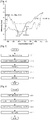
FIG. 3 is a graph showing the results of FTIR analysis on before/after the inner surface of the cooking chamber is polluted in the embodiment of the cooker according to the present invention; -
FIG. 4 is a graph showing the results of FTIR analysis on before/after the inner surface of the cooking chamber is polluted in the embodiment of the cooker according to the related art; -
FIG. 5 is a control flow chart showing a first embodiment of a method of manufacturing a cooker not forming part of this invention; -
FIG. 6 is a control flow chart showing a method not forming part of this invention; -
FIG. 7 is a control flow chart showing a method of manufacturing the cooker not forming part of this invention; -
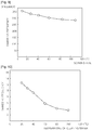
FIG. 8 is a graph showing the differences in cleaning frequency according to the temperature of cleaning water in the embodiment of the cooker according to the present invention; -
FIG. 9 is a graph showing the differences in cleaning frequency according to the temperature of cleaning water in the cooker according to the related art; -
FIG. 10 is a graph showing the differences in cleaning frequency according to the soaking time of cleaning water in the embodiment of the cooker according to the present invention; and -
FIG. 11 is a graph showing the differences in cleaning frequency according to the soaking time of cleaning water in the cooker according to the related art. - Hereinafter, the embodiment of a cooker according to the present invention will be described in detail with reference to the accompanying drawings.
-
FIG. 1 is a perspective view showing an embodiment of a cooker according to the present invention, andFIG. 2 is a longitudinal cross-sectional view showing the main part of the embodiment of the present invention. - Referring to
FIG. 1 , acavity 11 is provided inside amain body 10 of thecooker 1. Thecavity 11 forms acooking chamber 13 in which food is cooked. Thecavity 11 is formed in a hexahedral Thecavity 11 may be formed by at least one plate or a plurality of plates. As the plate forming thecavity 11, low carbon steel, for example, carbon steel whose carbon content is 0.008 wt% to 0.040 wt%, may be used. This is to facilitate the coating of a coating layer to be described later. - An out
case 15 forms the appearance of an upper surface and both side surfaces of themain body 10. The outcase 15 surrounds the upper portion and both sides of thecavity 11. - A
control panel 17 is installed on a front upper portion of themain body 10 corresponding to the upper of thecooking chamber 13. Thecontrol panel 17 includes aninput unit 17A that receives signals for operating thecooker 1 and anoutput unit 17B that outputs the signals of the operation of thecooker 11. In the present embodiment, theoutput unit 17B is shown as a display that outputs visual signals, but theoutput unit 17B can output at least one of visual and auditory signals. Also, if a soaking time to be described later is completed, theoutput unit 17B outputs signals informing thereof. - A plurality of heating sources that heat food are provided in the
cavity 11. Thecavity 11 includes anupper heater 19, alower heater 21, and aconvection device 23. Theupper heater 19 and thelower heater 21 are installed on the upper and the lower of thecooking chamber 13, respectively. And, theconvection device 23 is installed at the rear surface of thecooking chamber 13. Theupper heater 19 and thelower heater 21 perform radiant heat on the food inside thecooking chamber 13, and theconvection device 23 performs convection heating on food inside thecooking chamber 13. - The
cooking chamber 13 is selectively opened and closed by adoor 25. Thedoor 25 opens and closes thecooking chamber 13 in a pull-down scheme that its upper is vertically rotated to themain body 10 centering on the lower thereof - Meanwhile, a coating layer is provided on the inner surface of the
cooking chamber 13, that is, on the surface of thecavity 11. The coating layer is substantially provided on the surface of the plate that forms thecavity 11. The coating layer serves to improve heat-resistance, acid-resistance, durability, and cleanness of the inner surface of thecooking chamber 13. Referring toFIG. 2 , the coating layer includes first andsecond coating layers - More specifically, the
first coating layer 30 is coated directly on the surface of thecavity 11. In the present embodiment, thefirst coating layer 30 contains ceramic components that constitute a general enamel coating layer. And, thesecond coating layer 40 is coated on the surface of thefirst coating layer 30. Thesecond coating layer 40 contains phosphate-based (PxOy) components. Therefore, the first andsecond coating layers second coating layer 40 relatively have hydrophilicity compared to the ceramic components contained by thefirst coating layer 30. And, the absorption between thesecond coating layer 40 relatively having hydrophilicity as described above and the pollutants generated during the cooking process of food inside thecooking chamber 13 are bonded by relatively small magnitude of force compared to the absorption between the enamel coating layer and the pollutants in the related art. The detailed description thereof will be described later. - Meanwhile, the
second coating layer 40 includes 27.1-35.3 wt% P2O5, 14.6-28.4 wt% Al2O3, 12.8-20.3 wt% ZrO2, 18.7-28.8 wt% mother glass constitution components, and 17.2-25.4 wt% ceramic fillers. More preferably, thesecond coating layer 40 is a cooker including 28.7-33.4 wt% P2O5, 15.2-24.3 wt% Al2O3, 13.5-17.2 wt% ZrO2, 19.6 -26.5 wt% mother glass constitution components, and 17.8-22.4 wt% ceramic fillers. - Herein, the mother glass constitution components may include at least one of BaO, K 2O, Na2O, Co2O3, ZnO, Li2O, TiO2, B2O3, P2O5, and SiO2. And, the ceramic fillers may include at least one of ZrSiO4, ZrO2·SiO2, ZrO2, eucryptite, Al2O3, 2MgO 2Al2O3·5SiO2, and zinc compound.
- In the present embodiment, the hydrophilicity of the
second coating layer 40 is in proportion to the content of P2O5. The increase in the hydrophilicity of thesecond coating layer 40 allows the pollutants generated during the process of cooking and heating food inside thecooking chamber 13 and absorbed to thesecond coating layer 40 to be easily removed by a polar solvent. This will be described later. - The softening point of the
second coating layer 40 is in proportion to the content of the ceramic filler. Therefore, the heat-resistance of thesecond coating layer 40 can be improved by increasing the content of the ceramic filler. The selection of the ceramic filler may be made in consideration of low thermal expansion coefficient, etc. - Meanwhile, the
first coating layer 30 and thesecond coating layer 40 are coated on the inner surface of thecooking chamber 13 and the surface of thefirst coating layer 30, respectively, at a predetermined thickness. For example, the thickness T1 of thefirst coating layer 30 may be set to the value in the range of about 20 to 200µm. And, the thickness T2 of thesecond coating layer 40 may be set to the value in the range of about 80-300µm. Also, the sum of the thickness of the first and second coating layers 30 and 40 may be set to the value of 320µm or less. Preferably, the thickness T1 and T2 of thefirst coating layer 30 and thesecond coating layer 40 may be set to the values in the range of about 70-80µm and 100-0120µm, respectively, and the sum T3 of the thickness of the first and second coating layers 30 and 40 may be set to the value in the range of about 170-200µm. However, the thickness of thefirst coating layer 30 is set to the value below the thickness of thesecond coating layer 40. - The thickness of the first and second coating layers 30 and 40 as above is for securing intensity in consideration of the thermal expansion of the first and second coating layers 30 and 40. In other words, as the thickness of the first and second coating layers become thick, the intensity thereof is increased, but it may lead to the damage by the thermal expansion of the first and second coating layers 30 and 40. To the contrary, as the thickness of the first and second coating layers 30 and 40 become thin, it may lead to the reaction with the inner surface of the
cooking chamber 13, that is, an iron plate forming thecavity 11, as well as the lowering in the intensity. If the thickness of thefirst coating layer 80, the thickness of thesecond coating layer 40, and the thickness of the first and second coating layers 30 and 40 are determined within the range as described above, the sufficient intensity can be secured, while preventing the damage due to the thermal expansion of the first and second coating layers 30 and 40. - Hereinafter, the embodiment of the cooker according to the present invention will be compared with the absorption of the cooking chamber in the related art.
-
FIG. 3 is a graph showing the results of FTIR analysis on before/after the inner surface of the cooking chamber is polluted in the embodiment of the cooker according to the present invention, andFIG. 4 is a graph showing the results of FTIR analysis on before/after the inner surface of the cooking chamber is polluted in the embodiment of the cooker according to the related art. - First, referring to
FIG. 3 , in the cooker according to the embodiment of the present invention, a chemical bonding between thesecond coating layer 40 and the pollutants are not definitely found on the inner surface of thecooking chamber 13. Therethrough, it can be appreciated that the absorption between thesecond coating layer 40 and the pollutants is caused by van der waals reciprocal action, that is, van der waals interaction. - Meanwhile, referring to
FIG. 4 , in the cooker according to the related art in which an enamel coating layer formed of ceramic material is coated on the inner surface of thecooking chamber 13, a chemical bonding between Si that is the main component of the enamel coating layer and hydrocarbon (CnHm)-based that is the molecular structure of organic material constituting the pollutants is found. This means that as the pollutants and Si-O-Si on the surface of the enamel coating layer forms a chemical bonding, the enamel coating layer and the pollutants are relatively strongly absorbed compared to the van der waals interactions between thesecond coating layer 40 and the pollutants as described. In other words, in the related art, the pollutants of oil or organic material such as protein to be dispersed while heating and cooking food inside thecooking chamber 13 are absorbed and chemically bonded to the enamel surface layer under high temperature. - Therefore, with the present invention, the pollutants are absorbed to the
second coating layer 40 by the van der waals interaction so that the pollutants are absorbed by relatively weak force compared to the pollutants absorbed to the enamel coating layer by the chemical bonding in the cooker according to the related art. Therefore, it can be appreciated that the pollutants absorbed to thesecond coating layer 40, that is, thesecond coating layer 40 containing a much greater quantity of hydrophilic components, can be easily removed compared to the pollutants absorbed to the enamel coating layer in the related art. - Referring to
FIG. 5 first, a plate that forms an inner surface of acooking chamber 13, that is, acavity 11, is pretreated (S11). The pretreatment of the plate is for removing anti corrosion oil, etc. on the surface of low carbon steel that forms the plate. - Then, a
first coating layer 30 is coated on the surface of the plate (S13). Then, the plate coated with thefirst coating layer 30 is annealed (S15). Next, asecond coating layer 40 is coated on the surface of thefirst coating layer 30. Finally, the plate coated with the first and second coating layers 30 and 40 is annealed (S19). - Referring to
FIG. 6 first, the surface of a plate that forms acavity 11 is pretreated (S21). Then, afirst coating layer 30 is coated on the surface of the plate (S23). Next, asecond coating layer 40 is coated on the surface of the first coating layer 30 (S25). Then, the plate coated with the first and second coating layers 30 and 40 is annealed (S27). - In the first and second examples of the method of manufacturing the cooker not forming part of this invention as described above, the coating of the first and second coating layers 30 and 40 on the surface of the plate that forms the
cavity 11 and the annealing of the plate coated with thefirst coating layer 30 or the first and second coaling layers 30 and 40 may be performed before the plate forms thecavity 11 or after the plate forms thecavity 11. Also, the first and second coating layers 30 and 40 may be coated on the surface of the plate or the surface of thefirst coating layer 30 in a wet manner or a dry manner. For example, the first and second coating layers 30 and 40 may be coated on the surface of the plate or the surface of thefirst coating layer 30 through wet impregnation or dry spray. - And, the forming of the cavity by the plate may be performed before or after the first and second coating layers 30 and 40 are coated on the surface of the plate. In other words, the first and second coating layers 30 and 40 may be coated after the
cavity 10 is formed by the plate or thecavity 10 may be formed by the plate coated with the first and second coating layers 30 and 40. Also, thecavity 10 may be formed by one plate or a plurality of plates. - First, referring to
FIG. 7 , first, if cooking of food inside acooking chamber 13 is completed, the cleaning water is supplied to the inside of the cooking chamber 13 (S31). At this time, the cleaning water is supplied to the inside of thecooking chamber 13, in a state where thecooking chamber 13 is shielded by adoor 25. Also, the supply of the cleaning water may be performed by a user or may be performed by a separate cleaning water supplying unit (not shown). And, if the cleaning water is supplied to the inside of thecooking chamber 13, a heating source is operated so that heat is supplied to the inside of the cooking chamber 13 (S33). - Next, if the heating source is operated, it is determined whether the temperature of the cleaning water supplied to the inside of the
cooking chamber 13 reaches a preset cleaning temperature (S35). And, if it is determined that the temperature of the cleaning water supplied to the inside of thecooking chamber 13 reaches the cleaning temperature in step S35, the operation of the heating source is terminated (S37). And, if the operation of the heating source is terminated, it is determined whether a preset soaking time is passed (S39). - The cleaning temperature and the soaking time in step 35 and step 39 are set to the temperature and time of the cleaning water by which pollutants generated, while cooking food inside the
cooking chamber 13, to be absorbed to the inner surface of thecooking chamber 13, substantially, the surface of thesecond coating layer 40, can be sufficiently soaked. - If it is determined that the soaking time is passed in
step 39, anoutput unit 17B informs a user of cleaning completion (S41). Therefore, the user can wipe the inside of thecooking chamber 13, while opening thecooking chamber 13 by opening thedoor 25. - The removal of the pollutants absorbed to the inner surface of the
cooking chamber 13, more specifically, thesecond coating layer 40, is performed as the van der waals interaction between thesecond coating layer 40 containing hydrophilic components and the pollutants is weaken by the hydrogen bonding among the cleaning water that is a polar solvent supplied to thesecond coating layer 40 and the inside of thecooking chamber 13. - More specifically, if the polar solvent having abundant hydrogen bonding such as water is supplied to the inside of the
cooking chamber 13, the molecular interaction between thesecond coating layer 40 and the pollutants, that is, the van der waals interaction 1-2 kal/mol, is weaken by the bonding between oxygen that is double-bonded to phosphorus pentoxide (P2O5) that constitutes thesecond coating layer 40 and water, that is, the hydrogen bonding 3-7 kcal/mole between oxygen of thesecond coating layer 40 and water molecules. In other words, the van der waals interaction between non-polar polymers absorbed to the polar surface is weaken by the hydrogen bonding between the polar surface and water, if moisture or steam is infiltrated. Therefore, non-polar polymers unstably absorbed to the polar surface can be easily removed by relatively small physical force. In the present embodiment, the hydrogen bonding with water that is polarity is induced by a pair of non-covalent electrons of oxygen that is double-bonded to the hydrophilic component of thesecond coating layer 40, that is, phosphorus pentoxide (P2O5), so that the van der waals interaction between thesecond coating layer 40 and the pollutants is weaken, thereby making it possible to easily remove the pollutants from thesecond coating layer 40 with small physical force. In other words, with the present invention, the much easier removal of the pollutants can be expected compared to the related art in which the pollutants are absorbed to the enamel coating layer formed of general ceramic material by the chemical bonding therebetween. - This can be more easily appreciated with reference to
FIGS. 8 to 11 .FIGS. 8 and9 show swabbing frequency according to the temperature of cleaning water in a state where a chicken is heated inside thecooking chamber 13 at a temperature of 230°C for one hour and a half, the cleaning water is supplied to the inside of thecooking chamber 13, and then a soaking time of three minutes is passed. In other words, as shown inFIG. 8 , in the present invention, the pollutants absorbed to the inner surface of thecooking chamber 13 can be removed by swabbing of approximately six to twelve times. However, as shown inFIG. 9 , the pollutants absorbed to the inner surface of the cooking chamber are removed by swabbing of three hundred times or so. Also,FIGS. 10 and11 show swabbing frequency according to a soaking time in a state where a chicken is heated inside thecooking chamber 13 at a temperature of 230°C for one hour and a half and cleaning water at 20°C is supplied to the inside of thecooking chamber 13. In other words, as shown inFIG. 10 , the pollutants absorbed to the inner surface of thecooking chamber 13 can be removed by swabbing of approximately four to thirteen times. However, as shown inFIG. 11 , the pollutants absorbed to the inner surface of the cooking chamber are removed by swabbing of three hundred times or so. - Meanwhile, as the factors affecting the removal of the pollutants absorbed to the inner surface of the
cooking chamber 13, there may be (1) the ratio of component of the second coating layer, (2) the contact state and contact area between the polar solvent and the second coating layer, (3) the temperature of the polar solvent, (4) the contact time between the polar solvent and the second coating layer, etc. - Herein, the temperature of the polar solvent and the contact time between the polar solvent and the second coating layer may be represented by the temperature of the cleaning water and the soaking time by the cleaning water. In other words, the removal of the pollutants absorbed to the inner surface of the
cooking chamber 13, that is, clean, may be different according to the temperature of the cleaning water and the soaking time by the cleaning water. - Therefore, referring to
FIG. 8 again, it can be appreciated that the swabbing frequency in the cooker according to the present invention, that is, clean, is different according to the temperature of the cleaning water supplied to the inside of thecooking chamber 13. More specifically, in the embodiment according to the present invention, it can be appreciated that if the temperature of the cleaning water supplied to the inside of thecooking chamber 13 is increased to be 40°C or higher, the swabbing frequency for removing the pollutants absorbed to the inner surface of thecooking chamber 13 is significantly reduced. However, if the temperature of the cleaning water supplied to the inside of thecooking chamber 13 is increased to be 60°C or higher, the evaporation amount of the cleaning water supplied to the inside of thecooking chamber 13 may be increased so that it may, on the contrary, be hindered in overall cleaning the inner surface of thecooking chamber 13 - Referring to
FIG. 10 again, it can be appreciated that the swabbing frequency in the cooker according to the present invention, that is, clean, is different according to the soaking time by the cleaning water supplied to the inside of thecooking chamber 13. More specifically, in the embodiment according to the present invention, if the soaking time by the cleaning water supplied to the inside of thecooking chamber 13 is increased to be four minutes or more, preferably, six minutes or more, the swabbing frequency for removing the pollutants absorbed to the inner surface of thecooking chamber 13 is significantly reduced. - However, as shown in
FIGS. 10 and11 , it can be appreciated that in the case of the cooker according to the related art, that is, in the case where the general enamel coating layer is coated on the inner surface of the cooking chamber, the swabbing frequency is not significantly changed compared to the present invention, despite the change in the temperature of the cleaning water and the soaking time. Although the swabbing frequency is also changed in the related art according to the increase in the temperature of the cleaning water and the increase in the soaking time, significantly lots of swabbings are required compared to the present invention so that the reduction in the swabbing frequency according to the increase in the temperature of the cleaning water and the increase in the soaking time may be considered to be insignificant. - While the present invention has been described in connection with certain exemplary embodiments, it would be appreciated by those skilled in the art that changes might be made in this embodiment without departing from the scope of the invention as claimed.
- In the present embodiment, the first and second coating layers are described to be coated on the surface of the cavity corresponding to the inner surface of the cooking chamber, but the positions of the first and second coating layers are not always limited thereto. In other words, the first and second coating layers may be coated on other portions to which the pollutants generated during the cooking process of food inside the cooking chamber are absorbed, for example, the backside of the door.
- With the cooker as described above, the first coating layer that is a general ceramic enamel layer and the second coating layer that includes phosphate-based components are coated on the surface of the cavity corresponding to the inner surface of the cooking chamber. Therefore, the pollutants generated during the cooking process of food inside the cooking chamber and absorbed to the second coating layer can be easily removed.
Claims (12)
- A cooker (1) comprising:a cavity (11) that is provided with a cooking chamber (13) in which food is cooked;a heating source that provides heat for cooking food inside the cooking chamber (13);a door that selectively opens and closes the cooking chamber (13);an input unit (17A) that receives signals for cooking food inside the cooking chamber (13);an output unit (17B) that outputs the signals of the cooking inside the cooking chamber (13);a first coating layer (30) that is coated on the surface of the cavity (11) corresponding to the inner surface of the cooking chamber (13); anda second coating layer (40) that is coated on the surface of the first coating layer (30),characterized in that the second coating layer (40) includes 27.1-35.3 wt% P2O5, 14.6-28.4 wt% Al2O3, 12.8-20.3 wt% ZrO2, 18.7-28.8 wt% mother glass constitution components, and 17.2-25.4 wt% ceramic fillers.
- The cooker (1) according to claim 1, wherein the first coating layer (30) includes ceramic components.
- The cooker (1) according to claim 1 or 2, wherein the thickness of the first coating layer (30) is 200µm or less.
- The cooker according to any one of claims 1 to 3, wherein the thickness of the second coating layer (40) is 300µm or less.
- The cooker (1) according to claim 1 or 2, wherein the thickness of the first coating layer (30) is below the thickness of the second coating layer (40).
- The cooker (1) according to any one of claims 1 to 5, wherein the sum of the thickness of the first and second coating layers (30, 40) is 320µm or less.
- The cooker (1) according to any one of claims 1 to 6, wherein the cavity (11) is molded with low carbon steel whose carbon content is 0.008 wt% to 0.040 wt%.
- The cooker (1) according to any one of claims 1 to 7, wherein the first coating layer (30) is coated on the surface of the cavity (11), after the surface of the cavity (11) is pretreated, and
the second coating layer (40) is coated on the surface of the first coating layer (30), after the first coating layer (30) is coated on the surface of the cavity (11). - The cooker (1) according to claim 8, wherein the cavity (11) is annealed after at least one of the first coating layer (30) and the second coating layer (40) is coated.
- The cooker (1) according to claim 9, wherein the cavity (11) is annealed at any one time point of time points after the first coating layer (30) is coated before the second coating layer (40) is coated, and after the second coating layer (40) is coated.
- The cooker (1) according to any one of the claims 1 to 10, wherein the input unit (17A) receives signals for operating the heating source that heats cleaning water in a state where the cleaning water is supplied to the inside of the cooking chamber (13).
- The cooker (1) according to any one of the claims 1 to 11, wherein, when a preset time is passed in a state where the cleaning water is supplied to the inside of the cooking chamber (13) or a preset time is passed in a state where the heating source operating after the cleaning water is supplied to the inside of the cooking chamber (13) is stopped, the output unit (17B) outputs signals informing thereof.
Priority Applications (1)
| Application Number | Priority Date | Filing Date | Title |
|---|---|---|---|
| EP19162696.9A EP3531026B1 (en) | 2009-07-15 | 2010-07-12 | Cooker |
Applications Claiming Priority (2)
| Application Number | Priority Date | Filing Date | Title |
|---|---|---|---|
| KR20090064678 | 2009-07-15 | ||
| PCT/KR2010/004521 WO2011007991A2 (en) | 2009-07-15 | 2010-07-12 | Cooker and method of manufactruing and controlling the same |
Related Child Applications (2)
| Application Number | Title | Priority Date | Filing Date |
|---|---|---|---|
| EP19162696.9A Division-Into EP3531026B1 (en) | 2009-07-15 | 2010-07-12 | Cooker |
| EP19162696.9A Division EP3531026B1 (en) | 2009-07-15 | 2010-07-12 | Cooker |
Publications (3)
| Publication Number | Publication Date |
|---|---|
| EP2419677A2 EP2419677A2 (en) | 2012-02-22 |
| EP2419677A4 EP2419677A4 (en) | 2017-12-06 |
| EP2419677B1 true EP2419677B1 (en) | 2019-05-01 |
Family
ID=43449948
Family Applications (2)
| Application Number | Title | Priority Date | Filing Date |
|---|---|---|---|
| EP10800002.7A Active EP2419677B1 (en) | 2009-07-15 | 2010-07-12 | Cooker with cooking chamber having double coating layers |
| EP19162696.9A Active EP3531026B1 (en) | 2009-07-15 | 2010-07-12 | Cooker |
Family Applications After (1)
| Application Number | Title | Priority Date | Filing Date |
|---|---|---|---|
| EP19162696.9A Active EP3531026B1 (en) | 2009-07-15 | 2010-07-12 | Cooker |
Country Status (5)
| Country | Link |
|---|---|
| US (2) | US8955508B2 (en) |
| EP (2) | EP2419677B1 (en) |
| KR (1) | KR101695493B1 (en) |
| CN (1) | CN102422085B (en) |
| WO (1) | WO2011007991A2 (en) |
Families Citing this family (18)
| Publication number | Priority date | Publication date | Assignee | Title |
|---|---|---|---|---|
| WO2011003781A2 (en) | 2009-07-09 | 2011-01-13 | BSH Bosch und Siemens Hausgeräte GmbH | Steamer device |
| KR101695493B1 (en) * | 2009-07-15 | 2017-01-11 | 엘지전자 주식회사 | Cooker and method of controlling the same |
| EP3124876A1 (en) * | 2015-07-31 | 2017-02-01 | Electrolux Appliances Aktiebolag | A heatable cavity for a kitchen appliance having a low emissivity coating |
| KR102524063B1 (en) * | 2016-09-09 | 2023-04-21 | 삼성전자주식회사 | Oven |
| KR102373824B1 (en) * | 2017-09-06 | 2022-03-15 | 삼성전자주식회사 | Cooking apparatus and manufacturing method thereof |
| KR102071070B1 (en) * | 2018-02-28 | 2020-01-29 | 엘지전자 주식회사 | Coating composition and cooking appliance |
| KR102234552B1 (en) | 2018-10-31 | 2021-04-01 | 엘지전자 주식회사 | Composition for enamel, method for preparation thereof |
| KR102234551B1 (en) | 2018-11-09 | 2021-04-01 | 엘지전자 주식회사 | Composition for enamel, method for preparation thereof and cooking appliance |
| KR102172459B1 (en) | 2019-02-22 | 2020-10-30 | 엘지전자 주식회사 | Composition for enamel, method for preparation thereof and cooking appliance |
| KR20200102758A (en) | 2019-02-22 | 2020-09-01 | 엘지전자 주식회사 | Composition for enamel, method for preparation thereof and cooking appliance |
| KR102310341B1 (en) | 2019-02-22 | 2021-10-07 | 엘지전자 주식회사 | Composition for enamel, method for preparation thereof and cooking appliance |
| KR102172418B1 (en) | 2019-02-22 | 2020-10-30 | 엘지전자 주식회사 | Composition for enamel, method for preparation thereof and cooking appliance |
| KR102172416B1 (en) | 2019-02-22 | 2020-10-30 | 엘지전자 주식회사 | Composition for enamel, method for preparation thereof and cooking appliance |
| KR102172460B1 (en) | 2019-02-22 | 2020-10-30 | 엘지전자 주식회사 | Composition for enamel, method for preparation thereof and cooking appliance |
| KR102172417B1 (en) | 2019-02-22 | 2020-10-30 | 엘지전자 주식회사 | Composition for enamel, method for preparation thereof |
| EP3760931B1 (en) * | 2019-07-04 | 2025-06-25 | Electrolux Appliances Aktiebolag | Cooking oven with oven cavity and cooling channel |
| KR20220017431A (en) * | 2019-07-05 | 2022-02-11 | 베스텔 일렉트로닉 사나이 베 티카레트 에이에스 | Apparatus for cooking utensil, cooking utensil, and method of cleaning cooking utensil |
| CN114674014A (en) * | 2022-04-27 | 2022-06-28 | 杭州老板电器股份有限公司 | Enamel water receiving tray and preparation method of enamel water receiving tray |
Family Cites Families (38)
| Publication number | Priority date | Publication date | Assignee | Title |
|---|---|---|---|---|
| GB1096525A (en) * | 1963-12-14 | 1967-12-29 | Fuji Iron & Steel Company Ltd | Improvements in or relating to enameling-grade steel and materials and methods used in its production |
| US3547098A (en) | 1968-03-22 | 1970-12-15 | Ferro Corp | Porcelain enamels for self-cleaning cooking oven |
| US3545423A (en) * | 1969-01-13 | 1970-12-08 | Fedders Corp | Self-cleaning cooking apparatus |
| US3566855A (en) | 1969-10-21 | 1971-03-02 | Fedders Corp | Self-cleaning cooking apparatus |
| US4180609A (en) | 1975-07-11 | 1979-12-25 | E. I. Du Pont De Nemours And Company | Article coated with fluoropolymer finish with improved scratch resistance |
| CA1154638A (en) | 1978-03-15 | 1983-10-04 | Kunio Kimura | Method of forming porcelain enamels |
| JPS5854613B2 (en) | 1979-03-30 | 1983-12-06 | 三重油脂化工株式会社 | Film with oxidation catalytic action |
| JPS61291835A (en) | 1985-06-20 | 1986-12-22 | Matsushita Electric Ind Co Ltd | Heating unit |
| JP2732315B2 (en) * | 1989-05-29 | 1998-03-30 | 鐘淵化学工業株式会社 | Curing agent, method for producing the same, and curable composition using the curing agent |
| DE4212691A1 (en) * | 1992-04-16 | 1993-12-16 | Merck Patent Gmbh | Catalytically effective coating compound |
| JPH06147502A (en) | 1992-11-06 | 1994-05-27 | Hitachi Home Tec Ltd | Cooker, contaminant preventing cover material and painting method thereof |
| JP3748614B2 (en) * | 1995-11-30 | 2006-02-22 | 日本電気硝子株式会社 | Cooker top plate |
| DE19730610C1 (en) | 1997-07-17 | 1998-10-22 | Wiesheu Gmbh | Cleaning method for fan-assisted cooking oven with automatic cleaning cycle |
| KR100272357B1 (en) | 1997-10-10 | 2000-12-01 | 구자홍 | Removable oven cavity of gas oven range |
| JP3270733B2 (en) | 1998-01-16 | 2002-04-02 | シャープ株式会社 | Cooking surface structure of heating cooking appliance and method of manufacturing the same |
| EP0950644B1 (en) * | 1998-04-17 | 2002-07-03 | Ferro France S.A.R.L. | Porcelain enamel for aluminized steel |
| US6191389B1 (en) | 2000-03-31 | 2001-02-20 | General Electric Company | Grease resistant oven grille |
| EP1160283A1 (en) | 2000-05-29 | 2001-12-05 | Ferro France S.A.R.L. | Hybrid coating compositions |
| EP1167310A1 (en) | 2000-06-28 | 2002-01-02 | Ferro France S.A.R.L. | Enamel composition |
| EP1256556A1 (en) | 2001-05-09 | 2002-11-13 | Ferro France S.A.R.L. | Porcelain enamel composition |
| US6511931B1 (en) | 2001-07-16 | 2003-01-28 | Ferro Corporation | Easy-to-clean matte acid resistant ground coat |
| US20040069764A1 (en) | 2002-07-23 | 2004-04-15 | Matsushita Electric Industrial Co., Ltd | Heat cooking apparatus and self-cleaning functional material and manufacturing method thereof |
| KR100988570B1 (en) | 2003-04-10 | 2010-10-19 | 삼성전자주식회사 | Heating cooker |
| US7129745B2 (en) | 2004-05-19 | 2006-10-31 | Altera Corporation | Apparatus and methods for adjusting performance of integrated circuits |
| WO2006060751A2 (en) | 2004-12-03 | 2006-06-08 | Turbochef Technologies, Inc | High speed convection oven |
| US7005613B1 (en) | 2004-12-17 | 2006-02-28 | Saint-Gobain Performance Plastics Corporation | Method for cleaning ovens and merchandised article relating thereto |
| WO2006124415A2 (en) * | 2005-05-12 | 2006-11-23 | Ferro Corporation | Porcelain enamel having a metallic appearance |
| JP2007003186A (en) | 2006-06-23 | 2007-01-11 | Matsushita Electric Ind Co Ltd | Cooker |
| US7547369B2 (en) * | 2006-08-31 | 2009-06-16 | Ferro Corporation | Method of making multilayer structures using tapes on non-densifying substrates |
| KR101307752B1 (en) | 2006-10-10 | 2013-09-11 | 엘지전자 주식회사 | Cooking device & Cleaning method for the same |
| KR20080032708A (en) | 2006-10-10 | 2008-04-16 | 엘지전자 주식회사 | Cooking equipment and cleaning method |
| CN101182935A (en) | 2006-11-13 | 2008-05-21 | 乐金电子(天津)电器有限公司 | Micro-wave oven with washing bowls and cleaning container function |
| TWI497019B (en) * | 2007-01-30 | 2015-08-21 | Sumitomo Osaka Cement Co Ltd | Cooking utensil and method for manufacturing thereof |
| KR20090030974A (en) * | 2007-09-21 | 2009-03-25 | 삼성전자주식회사 | Cooking device and steam cleaning control method |
| KR101328419B1 (en) * | 2007-12-27 | 2013-11-14 | 동부대우전자 주식회사 | Cleaning control method of microwave |
| KR101457164B1 (en) * | 2008-06-16 | 2014-11-04 | 삼성전자 주식회사 | A coating composition, and a coating apparatus or a cooking vessel coated with the coating composition |
| KR20100034108A (en) * | 2008-09-23 | 2010-04-01 | 엘지전자 주식회사 | Oven |
| KR101695493B1 (en) * | 2009-07-15 | 2017-01-11 | 엘지전자 주식회사 | Cooker and method of controlling the same |
-
2010
- 2010-06-17 KR KR1020100057625A patent/KR101695493B1/en active Active
- 2010-07-08 US US12/832,722 patent/US8955508B2/en active Active
- 2010-07-12 EP EP10800002.7A patent/EP2419677B1/en active Active
- 2010-07-12 EP EP19162696.9A patent/EP3531026B1/en active Active
- 2010-07-12 CN CN201080020686.0A patent/CN102422085B/en active Active
- 2010-07-12 WO PCT/KR2010/004521 patent/WO2011007991A2/en not_active Ceased
-
2014
- 2014-12-05 US US14/561,474 patent/US9546792B2/en active Active
Non-Patent Citations (1)
| Title |
|---|
| None * |
Also Published As
| Publication number | Publication date |
|---|---|
| EP3531026A1 (en) | 2019-08-28 |
| US9546792B2 (en) | 2017-01-17 |
| EP3531026B1 (en) | 2021-10-20 |
| US8955508B2 (en) | 2015-02-17 |
| CN102422085A (en) | 2012-04-18 |
| WO2011007991A3 (en) | 2011-06-23 |
| US20150083109A1 (en) | 2015-03-26 |
| KR101695493B1 (en) | 2017-01-11 |
| US20110011423A1 (en) | 2011-01-20 |
| CN102422085B (en) | 2015-03-25 |
| WO2011007991A2 (en) | 2011-01-20 |
| EP2419677A4 (en) | 2017-12-06 |
| EP2419677A2 (en) | 2012-02-22 |
| KR20110007030A (en) | 2011-01-21 |
Similar Documents
| Publication | Publication Date | Title |
|---|---|---|
| EP3531026B1 (en) | Cooker | |
| KR101411034B1 (en) | A composition for enamel and a cooking appliance to which the enamel composition is applied | |
| US9074778B2 (en) | Cooking appliance surfaces having spill containment pattern | |
| US7695831B2 (en) | Coating composition, and cooking device or cooking receptacle coated with the same | |
| EP3578525B1 (en) | Glass composition and cooking appliance | |
| US11091387B2 (en) | Glass composition and cooking appliance | |
| US10899656B2 (en) | Glass composition, preparation method of glass composition, and cooking appliance | |
| KR20130125907A (en) | Composition for enamel, preparation method of composition for enamel, and cooking appliance | |
| KR20130125910A (en) | Composition for enamel, preparation method of composition for enamel, and cooking appliance | |
| KR20140115562A (en) | Composition for enamel, preparation method of composition for enamel, and cooking appliance | |
| KR102786001B1 (en) | Composition for enamel, method for preparation thereof and cooking appliance using the same | |
| US11912610B2 (en) | Coating composition having infrared reflective function, coating glass and method for preparation thereof, and cooking appliance using same | |
| KR101450917B1 (en) | Cooking equipment | |
| WO2006092941A1 (en) | Method for manufacturing water-using home facility or equipment, and water-using home facility or equipment | |
| US12290076B2 (en) | Baking tray or baking grid having a non-stick and/or non-wetting coating, cooking appliance comprising such a baking tray or baking grid and method for manufacturing a baking tray or baking grid | |
| US20110104502A1 (en) | Application of the Organic and/or Inorganic Refinishing of the Internal Face of the Exterior Glass of Oven's Door | |
| KR20230103200A (en) | Interior material for cooking apparatus, cooking apparatus and method for removing stain the same | |
| JPH10137132A (en) | Cooker and manufacturing method thereof |
Legal Events
| Date | Code | Title | Description |
|---|---|---|---|
| PUAI | Public reference made under article 153(3) epc to a published international application that has entered the european phase |
Free format text: ORIGINAL CODE: 0009012 |
|
| 17P | Request for examination filed |
Effective date: 20111109 |
|
| AK | Designated contracting states |
Kind code of ref document: A2 Designated state(s): AL AT BE BG CH CY CZ DE DK EE ES FI FR GB GR HR HU IE IS IT LI LT LU LV MC MK MT NL NO PL PT RO SE SI SK SM TR |
|
| DAX | Request for extension of the european patent (deleted) | ||
| A4 | Supplementary search report drawn up and despatched |
Effective date: 20171106 |
|
| RIC1 | Information provided on ipc code assigned before grant |
Ipc: C03C 8/08 20060101ALI20171027BHEP Ipc: F24C 3/00 20060101ALI20171027BHEP Ipc: F24C 7/00 20060101ALI20171027BHEP Ipc: F24C 15/00 20060101AFI20171027BHEP |
|
| GRAP | Despatch of communication of intention to grant a patent |
Free format text: ORIGINAL CODE: EPIDOSNIGR1 |
|
| STAA | Information on the status of an ep patent application or granted ep patent |
Free format text: STATUS: GRANT OF PATENT IS INTENDED |
|
| RIC1 | Information provided on ipc code assigned before grant |
Ipc: F24C 7/00 20060101ALI20181114BHEP Ipc: F24C 3/00 20060101ALI20181114BHEP Ipc: F24C 15/00 20060101AFI20181114BHEP Ipc: C03C 8/08 20060101ALI20181114BHEP |
|
| INTG | Intention to grant announced |
Effective date: 20181130 |
|
| RIC1 | Information provided on ipc code assigned before grant |
Ipc: C03C 8/08 20060101ALI20181119BHEP Ipc: F24C 15/00 20060101AFI20181119BHEP Ipc: F24C 14/00 20060101ALI20181119BHEP |
|
| GRAS | Grant fee paid |
Free format text: ORIGINAL CODE: EPIDOSNIGR3 |
|
| GRAA | (expected) grant |
Free format text: ORIGINAL CODE: 0009210 |
|
| STAA | Information on the status of an ep patent application or granted ep patent |
Free format text: STATUS: THE PATENT HAS BEEN GRANTED |
|
| AK | Designated contracting states |
Kind code of ref document: B1 Designated state(s): AL AT BE BG CH CY CZ DE DK EE ES FI FR GB GR HR HU IE IS IT LI LT LU LV MC MK MT NL NO PL PT RO SE SI SK SM TR |
|
| REG | Reference to a national code |
Ref country code: GB Ref legal event code: FG4D |
|
| REG | Reference to a national code |
Ref country code: CH Ref legal event code: EP Ref country code: AT Ref legal event code: REF Ref document number: 1127440 Country of ref document: AT Kind code of ref document: T Effective date: 20190515 |
|
| REG | Reference to a national code |
Ref country code: DE Ref legal event code: R096 Ref document number: 602010058617 Country of ref document: DE |
|
| REG | Reference to a national code |
Ref country code: IE Ref legal event code: FG4D |
|
| REG | Reference to a national code |
Ref country code: NL Ref legal event code: MP Effective date: 20190501 |
|
| REG | Reference to a national code |
Ref country code: LT Ref legal event code: MG4D |
|
| PG25 | Lapsed in a contracting state [announced via postgrant information from national office to epo] |
Ref country code: PT Free format text: LAPSE BECAUSE OF FAILURE TO SUBMIT A TRANSLATION OF THE DESCRIPTION OR TO PAY THE FEE WITHIN THE PRESCRIBED TIME-LIMIT Effective date: 20190901 Ref country code: AL Free format text: LAPSE BECAUSE OF FAILURE TO SUBMIT A TRANSLATION OF THE DESCRIPTION OR TO PAY THE FEE WITHIN THE PRESCRIBED TIME-LIMIT Effective date: 20190501 Ref country code: ES Free format text: LAPSE BECAUSE OF FAILURE TO SUBMIT A TRANSLATION OF THE DESCRIPTION OR TO PAY THE FEE WITHIN THE PRESCRIBED TIME-LIMIT Effective date: 20190501 Ref country code: LT Free format text: LAPSE BECAUSE OF FAILURE TO SUBMIT A TRANSLATION OF THE DESCRIPTION OR TO PAY THE FEE WITHIN THE PRESCRIBED TIME-LIMIT Effective date: 20190501 Ref country code: NL Free format text: LAPSE BECAUSE OF FAILURE TO SUBMIT A TRANSLATION OF THE DESCRIPTION OR TO PAY THE FEE WITHIN THE PRESCRIBED TIME-LIMIT Effective date: 20190501 Ref country code: FI Free format text: LAPSE BECAUSE OF FAILURE TO SUBMIT A TRANSLATION OF THE DESCRIPTION OR TO PAY THE FEE WITHIN THE PRESCRIBED TIME-LIMIT Effective date: 20190501 Ref country code: NO Free format text: LAPSE BECAUSE OF FAILURE TO SUBMIT A TRANSLATION OF THE DESCRIPTION OR TO PAY THE FEE WITHIN THE PRESCRIBED TIME-LIMIT Effective date: 20190801 Ref country code: HR Free format text: LAPSE BECAUSE OF FAILURE TO SUBMIT A TRANSLATION OF THE DESCRIPTION OR TO PAY THE FEE WITHIN THE PRESCRIBED TIME-LIMIT Effective date: 20190501 Ref country code: SE Free format text: LAPSE BECAUSE OF FAILURE TO SUBMIT A TRANSLATION OF THE DESCRIPTION OR TO PAY THE FEE WITHIN THE PRESCRIBED TIME-LIMIT Effective date: 20190501 |
|
| PGFP | Annual fee paid to national office [announced via postgrant information from national office to epo] |
Ref country code: FR Payment date: 20190719 Year of fee payment: 10 |
|
| PG25 | Lapsed in a contracting state [announced via postgrant information from national office to epo] |
Ref country code: LV Free format text: LAPSE BECAUSE OF FAILURE TO SUBMIT A TRANSLATION OF THE DESCRIPTION OR TO PAY THE FEE WITHIN THE PRESCRIBED TIME-LIMIT Effective date: 20190501 Ref country code: GR Free format text: LAPSE BECAUSE OF FAILURE TO SUBMIT A TRANSLATION OF THE DESCRIPTION OR TO PAY THE FEE WITHIN THE PRESCRIBED TIME-LIMIT Effective date: 20190802 Ref country code: BG Free format text: LAPSE BECAUSE OF FAILURE TO SUBMIT A TRANSLATION OF THE DESCRIPTION OR TO PAY THE FEE WITHIN THE PRESCRIBED TIME-LIMIT Effective date: 20190801 |
|
| REG | Reference to a national code |
Ref country code: AT Ref legal event code: MK05 Ref document number: 1127440 Country of ref document: AT Kind code of ref document: T Effective date: 20190501 |
|
| PG25 | Lapsed in a contracting state [announced via postgrant information from national office to epo] |
Ref country code: IS Free format text: LAPSE BECAUSE OF FAILURE TO SUBMIT A TRANSLATION OF THE DESCRIPTION OR TO PAY THE FEE WITHIN THE PRESCRIBED TIME-LIMIT Effective date: 20190901 |
|
| PGFP | Annual fee paid to national office [announced via postgrant information from national office to epo] |
Ref country code: GB Payment date: 20190729 Year of fee payment: 10 |
|
| PG25 | Lapsed in a contracting state [announced via postgrant information from national office to epo] |
Ref country code: CZ Free format text: LAPSE BECAUSE OF FAILURE TO SUBMIT A TRANSLATION OF THE DESCRIPTION OR TO PAY THE FEE WITHIN THE PRESCRIBED TIME-LIMIT Effective date: 20190501 Ref country code: SK Free format text: LAPSE BECAUSE OF FAILURE TO SUBMIT A TRANSLATION OF THE DESCRIPTION OR TO PAY THE FEE WITHIN THE PRESCRIBED TIME-LIMIT Effective date: 20190501 Ref country code: RO Free format text: LAPSE BECAUSE OF FAILURE TO SUBMIT A TRANSLATION OF THE DESCRIPTION OR TO PAY THE FEE WITHIN THE PRESCRIBED TIME-LIMIT Effective date: 20190501 Ref country code: EE Free format text: LAPSE BECAUSE OF FAILURE TO SUBMIT A TRANSLATION OF THE DESCRIPTION OR TO PAY THE FEE WITHIN THE PRESCRIBED TIME-LIMIT Effective date: 20190501 Ref country code: AT Free format text: LAPSE BECAUSE OF FAILURE TO SUBMIT A TRANSLATION OF THE DESCRIPTION OR TO PAY THE FEE WITHIN THE PRESCRIBED TIME-LIMIT Effective date: 20190501 Ref country code: DK Free format text: LAPSE BECAUSE OF FAILURE TO SUBMIT A TRANSLATION OF THE DESCRIPTION OR TO PAY THE FEE WITHIN THE PRESCRIBED TIME-LIMIT Effective date: 20190501 |
|
| REG | Reference to a national code |
Ref country code: DE Ref legal event code: R097 Ref document number: 602010058617 Country of ref document: DE |
|
| PG25 | Lapsed in a contracting state [announced via postgrant information from national office to epo] |
Ref country code: MC Free format text: LAPSE BECAUSE OF FAILURE TO SUBMIT A TRANSLATION OF THE DESCRIPTION OR TO PAY THE FEE WITHIN THE PRESCRIBED TIME-LIMIT Effective date: 20190501 Ref country code: SM Free format text: LAPSE BECAUSE OF FAILURE TO SUBMIT A TRANSLATION OF THE DESCRIPTION OR TO PAY THE FEE WITHIN THE PRESCRIBED TIME-LIMIT Effective date: 20190501 |
|
| REG | Reference to a national code |
Ref country code: CH Ref legal event code: PL |
|
| PLBE | No opposition filed within time limit |
Free format text: ORIGINAL CODE: 0009261 |
|
| STAA | Information on the status of an ep patent application or granted ep patent |
Free format text: STATUS: NO OPPOSITION FILED WITHIN TIME LIMIT |
|
| PG25 | Lapsed in a contracting state [announced via postgrant information from national office to epo] |
Ref country code: TR Free format text: LAPSE BECAUSE OF FAILURE TO SUBMIT A TRANSLATION OF THE DESCRIPTION OR TO PAY THE FEE WITHIN THE PRESCRIBED TIME-LIMIT Effective date: 20190501 |
|
| 26N | No opposition filed |
Effective date: 20200204 |
|
| REG | Reference to a national code |
Ref country code: BE Ref legal event code: MM Effective date: 20190731 |
|
| PG25 | Lapsed in a contracting state [announced via postgrant information from national office to epo] |
Ref country code: PL Free format text: LAPSE BECAUSE OF FAILURE TO SUBMIT A TRANSLATION OF THE DESCRIPTION OR TO PAY THE FEE WITHIN THE PRESCRIBED TIME-LIMIT Effective date: 20190501 |
|
| PG25 | Lapsed in a contracting state [announced via postgrant information from national office to epo] |
Ref country code: CH Free format text: LAPSE BECAUSE OF NON-PAYMENT OF DUE FEES Effective date: 20190731 Ref country code: LU Free format text: LAPSE BECAUSE OF NON-PAYMENT OF DUE FEES Effective date: 20190712 Ref country code: LI Free format text: LAPSE BECAUSE OF NON-PAYMENT OF DUE FEES Effective date: 20190731 Ref country code: BE Free format text: LAPSE BECAUSE OF NON-PAYMENT OF DUE FEES Effective date: 20190731 Ref country code: SI Free format text: LAPSE BECAUSE OF FAILURE TO SUBMIT A TRANSLATION OF THE DESCRIPTION OR TO PAY THE FEE WITHIN THE PRESCRIBED TIME-LIMIT Effective date: 20190501 |
|
| PG25 | Lapsed in a contracting state [announced via postgrant information from national office to epo] |
Ref country code: IE Free format text: LAPSE BECAUSE OF NON-PAYMENT OF DUE FEES Effective date: 20190712 |
|
| GBPC | Gb: european patent ceased through non-payment of renewal fee |
Effective date: 20200712 |
|
| PG25 | Lapsed in a contracting state [announced via postgrant information from national office to epo] |
Ref country code: FR Free format text: LAPSE BECAUSE OF NON-PAYMENT OF DUE FEES Effective date: 20200731 Ref country code: GB Free format text: LAPSE BECAUSE OF NON-PAYMENT OF DUE FEES Effective date: 20200712 |
|
| PG25 | Lapsed in a contracting state [announced via postgrant information from national office to epo] |
Ref country code: CY Free format text: LAPSE BECAUSE OF FAILURE TO SUBMIT A TRANSLATION OF THE DESCRIPTION OR TO PAY THE FEE WITHIN THE PRESCRIBED TIME-LIMIT Effective date: 20190501 |
|
| PG25 | Lapsed in a contracting state [announced via postgrant information from national office to epo] |
Ref country code: MT Free format text: LAPSE BECAUSE OF FAILURE TO SUBMIT A TRANSLATION OF THE DESCRIPTION OR TO PAY THE FEE WITHIN THE PRESCRIBED TIME-LIMIT Effective date: 20190501 Ref country code: HU Free format text: LAPSE BECAUSE OF FAILURE TO SUBMIT A TRANSLATION OF THE DESCRIPTION OR TO PAY THE FEE WITHIN THE PRESCRIBED TIME-LIMIT; INVALID AB INITIO Effective date: 20100712 |
|
| PG25 | Lapsed in a contracting state [announced via postgrant information from national office to epo] |
Ref country code: MK Free format text: LAPSE BECAUSE OF FAILURE TO SUBMIT A TRANSLATION OF THE DESCRIPTION OR TO PAY THE FEE WITHIN THE PRESCRIBED TIME-LIMIT Effective date: 20190501 |
|
| PGFP | Annual fee paid to national office [announced via postgrant information from national office to epo] |
Ref country code: DE Payment date: 20250609 Year of fee payment: 16 |
|
| PGFP | Annual fee paid to national office [announced via postgrant information from national office to epo] |
Ref country code: IT Payment date: 20250610 Year of fee payment: 16 |