EP2418813A2 - Wireless communications device with multiple demodulators and related methods - Google Patents
Wireless communications device with multiple demodulators and related methods Download PDFInfo
- Publication number
- EP2418813A2 EP2418813A2 EP11006230A EP11006230A EP2418813A2 EP 2418813 A2 EP2418813 A2 EP 2418813A2 EP 11006230 A EP11006230 A EP 11006230A EP 11006230 A EP11006230 A EP 11006230A EP 2418813 A2 EP2418813 A2 EP 2418813A2
- Authority
- EP
- European Patent Office
- Prior art keywords
- demodulation
- processor
- wireless communications
- threshold
- communications device
- Prior art date
- Legal status (The legal status is an assumption and is not a legal conclusion. Google has not performed a legal analysis and makes no representation as to the accuracy of the status listed.)
- Granted
Links
- 238000004891 communication Methods 0.000 title claims abstract description 74
- 238000000034 method Methods 0.000 title claims description 18
- 238000005070 sampling Methods 0.000 claims abstract description 19
- 238000012545 processing Methods 0.000 claims description 4
- 238000013459 approach Methods 0.000 description 4
- 230000005540 biological transmission Effects 0.000 description 4
- 238000012937 correction Methods 0.000 description 4
- 238000010586 diagram Methods 0.000 description 2
- 230000000694 effects Effects 0.000 description 2
- 238000005562 fading Methods 0.000 description 2
- 238000001228 spectrum Methods 0.000 description 2
- 239000000654 additive Substances 0.000 description 1
- 230000000996 additive effect Effects 0.000 description 1
- 125000004122 cyclic group Chemical group 0.000 description 1
- 230000001066 destructive effect Effects 0.000 description 1
- 230000000116 mitigating effect Effects 0.000 description 1
- XLYOFNOQVPJJNP-UHFFFAOYSA-N water Substances O XLYOFNOQVPJJNP-UHFFFAOYSA-N 0.000 description 1
Images



Classifications
-
- H—ELECTRICITY
- H04—ELECTRIC COMMUNICATION TECHNIQUE
- H04L—TRANSMISSION OF DIGITAL INFORMATION, e.g. TELEGRAPHIC COMMUNICATION
- H04L27/00—Modulated-carrier systems
- H04L27/0008—Modulated-carrier systems arrangements for allowing a transmitter or receiver to use more than one type of modulation
-
- H—ELECTRICITY
- H04—ELECTRIC COMMUNICATION TECHNIQUE
- H04L—TRANSMISSION OF DIGITAL INFORMATION, e.g. TELEGRAPHIC COMMUNICATION
- H04L27/00—Modulated-carrier systems
- H04L27/0012—Modulated-carrier systems arrangements for identifying the type of modulation
-
- H—ELECTRICITY
- H04—ELECTRIC COMMUNICATION TECHNIQUE
- H04L—TRANSMISSION OF DIGITAL INFORMATION, e.g. TELEGRAPHIC COMMUNICATION
- H04L1/00—Arrangements for detecting or preventing errors in the information received
- H04L1/004—Arrangements for detecting or preventing errors in the information received by using forward error control
- H04L1/0045—Arrangements at the receiver end
- H04L1/0046—Code rate detection or code type detection
-
- H—ELECTRICITY
- H04—ELECTRIC COMMUNICATION TECHNIQUE
- H04W—WIRELESS COMMUNICATION NETWORKS
- H04W52/00—Power management, e.g. Transmission Power Control [TPC] or power classes
- H04W52/02—Power saving arrangements
- H04W52/0209—Power saving arrangements in terminal devices
- H04W52/0225—Power saving arrangements in terminal devices using monitoring of external events, e.g. the presence of a signal
- H04W52/0229—Power saving arrangements in terminal devices using monitoring of external events, e.g. the presence of a signal where the received signal is a wanted signal
-
- H—ELECTRICITY
- H04—ELECTRIC COMMUNICATION TECHNIQUE
- H04W—WIRELESS COMMUNICATION NETWORKS
- H04W52/00—Power management, e.g. Transmission Power Control [TPC] or power classes
- H04W52/02—Power saving arrangements
- H04W52/0209—Power saving arrangements in terminal devices
- H04W52/0225—Power saving arrangements in terminal devices using monitoring of external events, e.g. the presence of a signal
- H04W52/0245—Power saving arrangements in terminal devices using monitoring of external events, e.g. the presence of a signal according to signal strength
-
- Y—GENERAL TAGGING OF NEW TECHNOLOGICAL DEVELOPMENTS; GENERAL TAGGING OF CROSS-SECTIONAL TECHNOLOGIES SPANNING OVER SEVERAL SECTIONS OF THE IPC; TECHNICAL SUBJECTS COVERED BY FORMER USPC CROSS-REFERENCE ART COLLECTIONS [XRACs] AND DIGESTS
- Y02—TECHNOLOGIES OR APPLICATIONS FOR MITIGATION OR ADAPTATION AGAINST CLIMATE CHANGE
- Y02D—CLIMATE CHANGE MITIGATION TECHNOLOGIES IN INFORMATION AND COMMUNICATION TECHNOLOGIES [ICT], I.E. INFORMATION AND COMMUNICATION TECHNOLOGIES AIMING AT THE REDUCTION OF THEIR OWN ENERGY USE
- Y02D30/00—Reducing energy consumption in communication networks
- Y02D30/70—Reducing energy consumption in communication networks in wireless communication networks
Definitions
- the present invention relates to the field of wireless communications, and, more particularly, to demodulation of signals with multipath characteristics and related methods.
- a typical wireless communication system comprises a plurality of wireless communications devices exchanging data with each other.
- the system may further comprise a wireless base station for managing communications between the wireless communications devices.
- each intra-system communication would be exchanged via the wireless base station.
- the wireless base station may be omitted, i.e., the wireless communications devices may communicate directly with each other.
- Multipath interference occurs when multiple signals of the same transmission arrive at the receiver wireless communications device, each signal traveling via a different path.
- the typical causes of multipath interference include, for example, atmospheric ducting, ionospheric reflection and refraction, and reflection from water bodies and terrestrial objects, such as mountains and buildings.
- the resulting multipath interference may be problematic.
- the multipath interference may prevent successful communications.
- the OpenSky wireless communication system may provide digital voice transport to radio communications applications and devices, i.e., handsets.
- the OpenSky communication system uses a Reed Solomon (RS) code to protect time division multiple access (TDMA) slots or bursts.
- RS Reed Solomon
- TDMA time division multiple access
- the OpenSky communication system may suffer from block error rates that prevent successful digital voice communications.
- the receiver device includes a plurality of parallel demodulators that track respective multipath signals. Each demodulator applies the same algorithm to each multipath element found and then combines all the demodulated results into one result prior to decoding. The receiver device searches for the most powerful multipath signals and assigns demodulators based upon a stored algorithm. In other words, this approach simply applies a standard rake receiver in a parallel manner.
- CDMA code division multiple access
- a wireless communications device that includes a receiver, and a processor coupled to the receiver.
- the processor is configured to perform a first demodulation based upon a first sampling rate of a received signal to generate a first demodulated signal and determine therefrom whether a first error value is not greater than a first threshold, and, if so then decode the first demodulated signal.
- the processor is then configured to perform a second demodulation based upon a second sampling rate of the received signal that is equal to or greater than the first sampling rate to generate a second demodulated signal and determine therefrom whether a second error value is not greater than a second threshold, and, if so, then decode the second demodulated signal. If the second error value is greater than the second threshold, the processor is configured to then perform the second demodulation at least one additional time with at least one change thereto.
- the processor sequentially makes use of the most effective demodulator algorithm for a given received signal with multipath characteristics, and unlike the typical device, the processor applies different demodulators in parallel.
- the processor may be configured to then add pseudo-random multipath characteristics to the received signal and perform the second demodulation.
- Another aspect is directed to a method of operating a wireless communications device comprising a receiver and a processor coupled to the receiver.
- the method comprises using the processor to perform a first demodulation based upon a first sampling rate of a received signal to generate a first demodulated signal and determine therefrom whether a first error value is not greater than a first threshold, and, if so then decode the first demodulated signal.
- the method also comprises if the first error value is greater than the first threshold, then using the processor to perform a second demodulation based upon a second sampling rate of the received signal that is the same or greater than the first sampling rate to generate a second demodulated signal and determine therefrom whether a second error value is not greater than a second threshold, and, if so, then using the processor to decode the second demodulated signal.
- the method further comprises if the second error value is greater than the second threshold, then using the processor to perform the second demodulation at least one additional time with at least one change thereto.
- FIG. 1 is a schematic block diagram of a wireless communication system, according to the present invention.
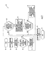
- FIG. 2 is a flowchart illustrating operation of the receiver wireless communications device of FIG. 1 .
- FIG. 3 is a schematic block diagram of another embodiment of the receiver wireless communications device, according to the present invention.
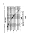
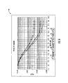
- FIGS. 4-6 are charts illustrating performance of the receiver wireless communications device of FIG. 1 .
- a wireless communication system 10 illustrates a method of operation of a receiver wireless communications device 11, which begins at Block 21.
- the wireless communications system 10 illustratively includes the receiver wireless communications device 11, and a transmitter wireless communications device 12 communicating therewith.
- the receiver wireless communications device 11 illustratively includes an antenna 15, a receiver 14 coupled to the antenna, and a processor 13 coupled to the receiver.
- the transmitter wireless communications device 12 illustratively includes an antenna 18, a transmitter 17 coupled to the antenna, and a processor 16 coupled to the transmitter.
- the wireless communications devices 11, 12 may include a plurality of differing types of wireless communications devices modified according to the teachings herein, for example, the Falcon ® III/117G manpack radio, or SBR/SPR handheld radio, as available from the Harris Corporation of Melbourne, FL, the assignee of the present application.
- the wireless communication system 10 illustratively uses a communication protocol including a form of error correction.
- the communication protocol may include a Gaussian Frequency-Shift Keying (GFSK) modulation waveform with forward error correction (FEC).
- FEC forward error correction
- the error correction may, for example, be a Reed Solomon (RS) code, a low-density parity-check (LDPC) code, and/or a cyclic redundancy check (CRC) code.
- RS Reed Solomon
- LDPC low-density parity-check
- CRC cyclic redundancy check
- the communication protocol may be based upon time division multiple access (TDMA) and be adapted for burst slotted TDMA communications.
- TDMA time division multiple access
- the transmitter wireless communications device 12 transmits a modulated signal to the receiver wireless communications device 11.
- the modulated signal illustratively crosses hilly terrain, which would create multipath propagation.
- the receiver wireless communications device 11 will experience multipath effects when the modulated signal is received (Block 23).
- the hilly terrain is illustrative, the receiver wireless communications device 11 would be effective for receipt of a transmission through any physical medium that would create multipath propagation, such as an urban environment.
- the processor 13 When the modulated signal is received via the antenna 15 and the wireless receiver 14, the processor 13 is configured to perform a first demodulation based upon a first sampling rate of a received signal to generate a first demodulated signal (Block 25).
- the first demodulator may comprise a typical Gaussian Frequency-Shift Keying (GFSK) demodulator (which could comprise a FM (Frequency Modulation) demodulator followed by a direct current (DC) offset eliminator followed by a symbol-timing loop and a simple linear equalizer), and the first sampling rate may be 2 samples per data symbol.
- GFSK Gaussian Frequency-Shift Keying
- the processor 13 illustratively determines whether a first error value for the first demodulated signal is or is not greater than a first threshold.
- the first threshold may be zero, i.e., demanding an error free transmission, or some other value, such as an error value threshold suitable for voice communications. If the first error value from the first demodulated signal is not greater than a first threshold, the processor 13 then decodes the first demodulated signal (Blocks 43, 45).
- the processor 13 determines that the first error value is greater than the first threshold, the processor is configured to perform a second (enhanced) demodulation based upon a second sampling rate of the received signal that is the same or greater than the first sampling rate to generate a second demodulated signal (Block 31). Specifically, the processor 13 may interpolate the received signal to 16 samples per data symbol, for example.
- the processor 13 is configured to perform the second demodulation, which may include performing a FM demodulation, processing for a DC offset downstream from the FM demodulation, i.e., frequency error removal, applying at least one matched filter (where each matched filter comprises an integrate and dump over the symbol time minus a hypothesized multipath guard time) downstream from the FM demodulation, and determining symbol timing based on the greater samples per symbol stream and using a different algorithm than the first demodulation.
- the second demodulation may include performing a FM demodulation, processing for a DC offset downstream from the FM demodulation, i.e., frequency error removal, applying at least one matched filter (where each matched filter comprises an integrate and dump over the symbol time minus a hypothesized multipath guard time) downstream from the FM demodulation, and determining symbol timing based on the greater samples per symbol stream and using a different algorithm than the first demodulation.
- the processor 13 determines whether a second error value (associated with the second demodulated signal) is or is not greater than a second threshold.
- the first and second threshold may be the same value, i.e., equal, but in other embodiments, the threshold values may be tiered. If the processor 13 determines that second error value is not greater than the second threshold, the processor decodes the second demodulated signal (Blocks 43, 45).
- the processor 13 is configured to then perform the second demodulation at least one additional time with at least one change thereto (Block 35). More specifically, the at least one change may comprise at least one change in symbol time alignment (for example, in the aforesaid embodiment with 16x oversampling, there are 16 possible symbol time alignments). Further, the processor 13 is configured to perform the second demodulation at least one additional time by applying all the different time alignments to determine a closest match time alignment for the received signal (Block 35). In other words, the processor 13 is configured to apply each of the 16 possible alignments for each matched filter, using adjusted matched filter guard times. In some embodiments, the processor 13 is configured to provide an array of demodulated data symbols based upon the results from the 16 possible time alignments.
- the processor 13 is configured to begin the search for the best time alignment with the demodulated symbols with the least amount of mean squared error in the data symbols (relative to closest symbol constellation).
- the processor 13 is configured to move outward from this time alignment as the search progresses.
- the processor 13 For each symbol time alignment tested in the second demodulator, the processor 13 again checks subsequent second error values to determine if they are greater than, equal to, or less than the second threshold. Again, if a subsequent second error value is not greater than the second threshold, the processor 13 proceeds to decode the demodulated signal (Blocks 43, 45). After all time alignments have been tested, if all of the subsequent second error values exceed the second threshold, the processor 13 is configured to then add pseudo-random multipath characteristics (amplitude and phase dither) to the received signal and again perform the second demodulation (Blocks 37, 41).
- the pseudo-random multipath characteristics help address the undesired tone nulls that may occur with multipath destructive interference in the received signal.
- the processor 13 will select the time alignment with the least amount of symbol differences between it and symbols demodulated with adjacent time alignments, thus providing an output stream with a minimum number of errors.
- the receiver wireless communications device 11 efficiently and effectively demodulates the multipath received signal.
- the receiver wireless communications device 11 first applies the quick and efficient (resource consumption) first demodulation, which may be a simple GFSK demodulator.
- the receiver wireless communications device 11 then only applies an enhanced second demodulation if the first demodulation produces errors.
- the receiver wireless communications device 11 may readily determine if there are errors in the demodulated signal. If the first demodulated signal has errors, the receiver wireless communications device 11 then applies the second demodulation, which has significant enhancements over the first, which, of course, come with extra computational costs.
- the receiver wireless communications device 11 applies a search process to the second demodulator. If the demodulated signals from the search process all have unacceptable errors, then the receiver wireless communications device 11 applies pseudo-random multipath characteristics to the received signal. In short, the receiver wireless communications device 11 applies only the minimum demodulator complexity needed to secure a successful demodulation. In other words, if the relatively simple GFSK demodulator can achieve error free operation, the receiver wireless communications device 11 uses only the standard GFSK demodulator, and if a much more robust demodulator is needed for error free demodulation, the receiver wireless communications device 11 applies the appropriate demodulator.
- This device 50 illustratively includes a standard modem process module 51 receiving samples from a received signal.
- the standard modem process module 51 demodulates the received signal and provides symbol decisions based upon a standard GFSK demodulator, i.e., a FM demodulation, a DC bias removal processing thereafter, and the application of a symbol timing algorithm and a simple linear equalizer downstream from the DC bias removal processing.
- the device 50 illustratively includes an RS decoder 52 receiving the symbol decisions, and an error based iteration control module 53 cooperating with the RS decoder.
- the device 50 illustratively includes a second demodulation path including a multipath dither module 57, a 16x interpolator 54, an enhanced modem module 55, and a multipath dither RS decoder 56 (all coupled in this same order).
- a second demodulation path including a multipath dither module 57, a 16x interpolator 54, an enhanced modem module 55, and a multipath dither RS decoder 56 (all coupled in this same order).
- the device 50 includes a time alignment RS decoder 58 for decoding the demodulated signal at one or more of the possible symbol time alignments. In other words, the process of the enhanced modem module 55 is applied to all possible 16 symbol time alignments.
- charts 60, 70, 80 illustrate the performance of the receiver wireless communications device 11 in varying transmission channels using a public safety waveform meeting the National Public Safety Planning Advisory Committee (NPSPAC) spectrum requirements.
- NPSPAC National Public Safety Planning Advisory Committee
- the first chart 60 plots the receiver wireless communications device's 11 performance on an additive white Gaussian noise channel
- the second chart 70 plots the device's performance in a 1-path 40 Hz Doppler spread channel
- the third chart 80 plots the device's performance in a hilly terrain channel.
- curves 61, 71, 81 relate to the application of only the first demodulator
- curves 62, 72, 82 relate to the application of only the second enhanced demodulator
- curves 63, 73, 83 relate to the application of only the second enhanced demodulator using multiple time alignments
- curves 64, 74, 84 relate to the application of only the second enhanced demodulator with pseudo-random multipath characteristics.
- curves 65, 75, 85 relate to selective application of all the demodulators (first and second demodulator with multiple time alignment and with pseudo-random multipath characteristics). As shown by the charts 60, 70, 80, the performance of the receiver wireless communications device 11 is superior to the other methods alone by providing a lower voice block error rate (VBLER).
- VBLER voice block error rate
Landscapes
- Engineering & Computer Science (AREA)
- Signal Processing (AREA)
- Computer Networks & Wireless Communication (AREA)
- Noise Elimination (AREA)
- Mobile Radio Communication Systems (AREA)
Abstract
Description
- The present invention relates to the field of wireless communications, and, more particularly, to demodulation of signals with multipath characteristics and related methods.
- A typical wireless communication system comprises a plurality of wireless communications devices exchanging data with each other. In some wireless communication systems, for example, infrastructure networks, the system may further comprise a wireless base station for managing communications between the wireless communications devices. In other words, each intra-system communication would be exchanged via the wireless base station. In other wireless communication systems, for example, mesh networks and ad hoc wireless networks, the wireless base station may be omitted, i.e., the wireless communications devices may communicate directly with each other.
- One form of interference that the wireless communications device may encounter is multipath interference. Multipath interference occurs when multiple signals of the same transmission arrive at the receiver wireless communications device, each signal traveling via a different path. The typical causes of multipath interference include, for example, atmospheric ducting, ionospheric reflection and refraction, and reflection from water bodies and terrestrial objects, such as mountains and buildings.
- More specifically, when two wireless communications devices communicate over hilly terrain, the resulting multipath interference may be problematic. In some applications, for example, voice communications, the multipath interference may prevent successful communications.
- One approach to a wireless communication system is the OpenSky communication system, as available from the Harris Corporation of Melbourne, FL, the assignee of the present application. In particular, the OpenSky wireless communication system may provide digital voice transport to radio communications applications and devices, i.e., handsets. As will be appreciated by those skilled in the art, the OpenSky communication system uses a Reed Solomon (RS) code to protect time division multiple access (TDMA) slots or bursts. In fading multipath applications, for example, the hilly terrain (HT) channel (two
fading paths 13 µs apart with each path having a 40 Hz Doppler spread and where the power of the second path is 8.6 dB lower than the first path), the OpenSky communication system may suffer from block error rates that prevent successful digital voice communications. - An approach to mitigating multipath effects in a code division multiple access (CDMA) spread spectrum wireless communication system is disclosed in
U.S. Patent No. 5,654,979 to Levin et al . In this approach, the receiver device includes a plurality of parallel demodulators that track respective multipath signals. Each demodulator applies the same algorithm to each multipath element found and then combines all the demodulated results into one result prior to decoding. The receiver device searches for the most powerful multipath signals and assigns demodulators based upon a stored algorithm. In other words, this approach simply applies a standard rake receiver in a parallel manner. - In view of the foregoing background, it is therefore an object of the present invention to provide a wireless communications device that can readily demodulate received signals with multipath.
- This and other objects, features, and advantages in accordance with the present invention are provided by a wireless communications device that includes a receiver, and a processor coupled to the receiver. The processor is configured to perform a first demodulation based upon a first sampling rate of a received signal to generate a first demodulated signal and determine therefrom whether a first error value is not greater than a first threshold, and, if so then decode the first demodulated signal. If the first error value is greater than the first threshold, the processor is then configured to perform a second demodulation based upon a second sampling rate of the received signal that is equal to or greater than the first sampling rate to generate a second demodulated signal and determine therefrom whether a second error value is not greater than a second threshold, and, if so, then decode the second demodulated signal. If the second error value is greater than the second threshold, the processor is configured to then perform the second demodulation at least one additional time with at least one change thereto.
- Advantageously, the processor sequentially makes use of the most effective demodulator algorithm for a given received signal with multipath characteristics, and unlike the typical device, the processor applies different demodulators in parallel.
- Moreover, if at least one subsequent second error value for the at least one additional performance of the second demodulation is greater than the second threshold, the processor may be configured to then add pseudo-random multipath characteristics to the received signal and perform the second demodulation.
- Another aspect is directed to a method of operating a wireless communications device comprising a receiver and a processor coupled to the receiver. The method comprises using the processor to perform a first demodulation based upon a first sampling rate of a received signal to generate a first demodulated signal and determine therefrom whether a first error value is not greater than a first threshold, and, if so then decode the first demodulated signal. The method also comprises if the first error value is greater than the first threshold, then using the processor to perform a second demodulation based upon a second sampling rate of the received signal that is the same or greater than the first sampling rate to generate a second demodulated signal and determine therefrom whether a second error value is not greater than a second threshold, and, if so, then using the processor to decode the second demodulated signal. The method further comprises if the second error value is greater than the second threshold, then using the processor to perform the second demodulation at least one additional time with at least one change thereto.
-
FIG. 1 is a schematic block diagram of a wireless communication system, according to the present invention. -
FIG. 2 is a flowchart illustrating operation of the receiver wireless communications device ofFIG. 1 . -
FIG. 3 is a schematic block diagram of another embodiment of the receiver wireless communications device, according to the present invention. -
FIGS. 4-6 are charts illustrating performance of the receiver wireless communications device ofFIG. 1 . - The present invention will now be described more fully hereinafter with reference to the accompanying drawings, in which preferred embodiments of the invention are shown. This invention may, however, be embodied in many different forms and should not be construed as limited to the embodiments set forth herein. Rather, these embodiments are provided so that this disclosure will be thorough and complete, and will fully convey the scope of the invention to those skilled in the art. Like numbers refer to like elements throughout.
- Referring initially to
FIGS. 1-2 , awireless communication system 10 according to the present invention is now described. OnFIG. 2 , aflowchart 20 illustrates a method of operation of a receiverwireless communications device 11, which begins atBlock 21. Referring now back toFIG. 1 , thewireless communications system 10 illustratively includes the receiverwireless communications device 11, and a transmitterwireless communications device 12 communicating therewith. The receiverwireless communications device 11 illustratively includes anantenna 15, areceiver 14 coupled to the antenna, and aprocessor 13 coupled to the receiver. The transmitterwireless communications device 12 illustratively includes anantenna 18, atransmitter 17 coupled to the antenna, and aprocessor 16 coupled to the transmitter. As will be appreciated by those skilled in the art, thewireless communications devices - The
wireless communication system 10 illustratively uses a communication protocol including a form of error correction. For example, the communication protocol may include a Gaussian Frequency-Shift Keying (GFSK) modulation waveform with forward error correction (FEC). In particular, the error correction may, for example, be a Reed Solomon (RS) code, a low-density parity-check (LDPC) code, and/or a cyclic redundancy check (CRC) code. For example, the communication protocol may be based upon time division multiple access (TDMA) and be adapted for burst slotted TDMA communications. - As illustrated, the transmitter
wireless communications device 12 transmits a modulated signal to the receiverwireless communications device 11. The modulated signal illustratively crosses hilly terrain, which would create multipath propagation. In other words, the receiverwireless communications device 11 will experience multipath effects when the modulated signal is received (Block 23). Of course, the hilly terrain is illustrative, the receiverwireless communications device 11 would be effective for receipt of a transmission through any physical medium that would create multipath propagation, such as an urban environment. - When the modulated signal is received via the
antenna 15 and thewireless receiver 14, theprocessor 13 is configured to perform a first demodulation based upon a first sampling rate of a received signal to generate a first demodulated signal (Block 25). For example, the first demodulator may comprise a typical Gaussian Frequency-Shift Keying (GFSK) demodulator (which could comprise a FM (Frequency Modulation) demodulator followed by a direct current (DC) offset eliminator followed by a symbol-timing loop and a simple linear equalizer), and the first sampling rate may be 2 samples per data symbol. - At
decision Block 27, theprocessor 13 illustratively determines whether a first error value for the first demodulated signal is or is not greater than a first threshold. For example, the first threshold may be zero, i.e., demanding an error free transmission, or some other value, such as an error value threshold suitable for voice communications. If the first error value from the first demodulated signal is not greater than a first threshold, theprocessor 13 then decodes the first demodulated signal (Blocks 43, 45). - On the other hand, if the
processor 13 determines that the first error value is greater than the first threshold, the processor is configured to perform a second (enhanced) demodulation based upon a second sampling rate of the received signal that is the same or greater than the first sampling rate to generate a second demodulated signal (Block 31). Specifically, theprocessor 13 may interpolate the received signal to 16 samples per data symbol, for example. Further, theprocessor 13 is configured to perform the second demodulation, which may include performing a FM demodulation, processing for a DC offset downstream from the FM demodulation, i.e., frequency error removal, applying at least one matched filter (where each matched filter comprises an integrate and dump over the symbol time minus a hypothesized multipath guard time) downstream from the FM demodulation, and determining symbol timing based on the greater samples per symbol stream and using a different algorithm than the first demodulation. - At
decision Block 33, theprocessor 13 then determines whether a second error value (associated with the second demodulated signal) is or is not greater than a second threshold. In some embodiments, the first and second threshold may be the same value, i.e., equal, but in other embodiments, the threshold values may be tiered. If theprocessor 13 determines that second error value is not greater than the second threshold, the processor decodes the second demodulated signal (Blocks 43, 45). - If the second error value is greater than the second threshold, the
processor 13 is configured to then perform the second demodulation at least one additional time with at least one change thereto (Block 35). More specifically, the at least one change may comprise at least one change in symbol time alignment (for example, in the aforesaid embodiment with 16x oversampling, there are 16 possible symbol time alignments). Further, theprocessor 13 is configured to perform the second demodulation at least one additional time by applying all the different time alignments to determine a closest match time alignment for the received signal (Block 35). In other words, theprocessor 13 is configured to apply each of the 16 possible alignments for each matched filter, using adjusted matched filter guard times. In some embodiments, theprocessor 13 is configured to provide an array of demodulated data symbols based upon the results from the 16 possible time alignments. - Further, the
processor 13 is configured to begin the search for the best time alignment with the demodulated symbols with the least amount of mean squared error in the data symbols (relative to closest symbol constellation). Theprocessor 13 is configured to move outward from this time alignment as the search progresses. - For each symbol time alignment tested in the second demodulator, the
processor 13 again checks subsequent second error values to determine if they are greater than, equal to, or less than the second threshold. Again, if a subsequent second error value is not greater than the second threshold, theprocessor 13 proceeds to decode the demodulated signal (Blocks 43, 45). After all time alignments have been tested, if all of the subsequent second error values exceed the second threshold, theprocessor 13 is configured to then add pseudo-random multipath characteristics (amplitude and phase dither) to the received signal and again perform the second demodulation (Blocks 37, 41). Advantageously, the pseudo-random multipath characteristics help address the undesired tone nulls that may occur with multipath destructive interference in the received signal. Of course, if all of the subsequent second error values (for the multiple demodulated signals in the search space) exceed the second threshold, even with the addition of pseudo-random multipath characteristics, theprocessor 13 will select the time alignment with the least amount of symbol differences between it and symbols demodulated with adjacent time alignments, thus providing an output stream with a minimum number of errors. - The receiver
wireless communications device 11 efficiently and effectively demodulates the multipath received signal. The receiverwireless communications device 11 first applies the quick and efficient (resource consumption) first demodulation, which may be a simple GFSK demodulator. The receiverwireless communications device 11 then only applies an enhanced second demodulation if the first demodulation produces errors. Of course, since the communication protocol has built-in error correction, the receiverwireless communications device 11 may readily determine if there are errors in the demodulated signal. If the first demodulated signal has errors, the receiverwireless communications device 11 then applies the second demodulation, which has significant enhancements over the first, which, of course, come with extra computational costs. - Again, only if the second demodulated signal has unacceptable errors does the receiver
wireless communications device 11 apply a search process to the second demodulator. If the demodulated signals from the search process all have unacceptable errors, then the receiverwireless communications device 11 applies pseudo-random multipath characteristics to the received signal. In short, the receiverwireless communications device 11 applies only the minimum demodulator complexity needed to secure a successful demodulation. In other words, if the relatively simple GFSK demodulator can achieve error free operation, the receiverwireless communications device 11 uses only the standard GFSK demodulator, and if a much more robust demodulator is needed for error free demodulation, the receiverwireless communications device 11 applies the appropriate demodulator. - Referring to
FIG. 3 , anexemplary implementation 50 of the aforementioned receiverwireless communications device 11 is illustrated. Thisdevice 50 illustratively includes a standardmodem process module 51 receiving samples from a received signal. The standardmodem process module 51 demodulates the received signal and provides symbol decisions based upon a standard GFSK demodulator, i.e., a FM demodulation, a DC bias removal processing thereafter, and the application of a symbol timing algorithm and a simple linear equalizer downstream from the DC bias removal processing. Thedevice 50 illustratively includes anRS decoder 52 receiving the symbol decisions, and an error basediteration control module 53 cooperating with the RS decoder. Thedevice 50 illustratively includes a second demodulation path including amultipath dither module 57, a16x interpolator 54, anenhanced modem module 55, and a multipath dither RS decoder 56 (all coupled in this same order). - If the
control module 53 indicates that there are errors in the demodulated signal from the standardmodem process module 51, the received signal samples are fed into the second demodulation path for demodulation. If thecontrol module 53 indicates that the demodulated signal from the second demodulation path has errors, thedevice 50 includes a timealignment RS decoder 58 for decoding the demodulated signal at one or more of the possible symbol time alignments. In other words, the process of theenhanced modem module 55 is applied to all possible 16 symbol time alignments. - Referring now to
FIGS. 4-6 , charts 60, 70, 80 illustrate the performance of the receiverwireless communications device 11 in varying transmission channels using a public safety waveform meeting the National Public Safety Planning Advisory Committee (NPSPAC) spectrum requirements. In particular, the first chart 60 plots the receiver wireless communications device's 11 performance on an additive white Gaussian noise channel, thesecond chart 70 plots the device's performance in a 1-path 40 Hz Doppler spread channel, and thethird chart 80 plots the device's performance in a hilly terrain channel. The corresponding plotted curves on each chart relate to performance of particular demodulators, i.e., curves 61, 71, 81 relate to the application of only the first demodulator, curves 62, 72, 82 relate to the application of only the second enhanced demodulator, curves 63, 73, 83 relate to the application of only the second enhanced demodulator using multiple time alignments, and curves 64, 74, 84 relate to the application of only the second enhanced demodulator with pseudo-random multipath characteristics. - As in the receiver
wireless communications device 11, curves 65, 75, 85 relate to selective application of all the demodulators (first and second demodulator with multiple time alignment and with pseudo-random multipath characteristics). As shown by thecharts wireless communications device 11 is superior to the other methods alone by providing a lower voice block error rate (VBLER).
Claims (10)
- A wireless communications device comprising:a receiver; anda processor coupled to said receiver and configured to:perform a first demodulation based upon a first sampling rate of a received signal to generate a first demodulated signal and determine therefrom whether a first error value is not greater than a first threshold, and, if so then decode the first demodulated signal,if the first error value is greater than the first threshold, then perform a second demodulation based upon a second sampling rate of the received signal greater than or equal to the first sampling rate to generate a second demodulated signal and determine therefrom whether a second error value is not greater than a second threshold, and, if so, then decode the second demodulated signal, andif the second error value is greater than the second threshold, then perform the second demodulation at least one additional time with at least one change thereto.
- The wireless communications device according to Claim 1 wherein said processor is configured to provide the at least one change comprising at least one change in symbol time alignment.
- The wireless communications device according to Claim 2 wherein said processor is configured to perform the second demodulation at least one additional time by at least applying different symbol time alignments to determine a closest match symbol time alignment for the received signal.
- The wireless communications device according to Claim 1 wherein the first and second thresholds are equal.
- The wireless communications device according to Claim 1 wherein said processor is configured to perform the second demodulation to include performing a frequency modulation (FM) demodulation, processing a direct current (DC) offset on the FM demodulation, and applying at least one matched filter downstream from the DC offset.
- The wireless communications device according to Claim 1 wherein if at least one subsequent second error value for the at least one additional application of the second demodulator is greater than the second threshold, said processor is configured to then add pseudo-random multipath characteristics to the received signal and perform the second demodulation.
- The wireless communications device according to Claim 1 wherein said processor is configured to provide an array of demodulated data symbols based upon the second demodulation.
- A method of operating a wireless communications device comprising a receiver and a processor coupled to the receiver, the method comprising:performing using the processor a first demodulation based upon a first sampling rate of a received signal and generating a first demodulated signal and determining therefrom whether a first error value is not greater than a first threshold, and, if so then decoding the first demodulated signal;if the first error value is greater than the first threshold, then performing using the processor a second demodulation based upon a second sampling rate of the received signal greater than or equal to the first sampling rate and generating a second demodulated signal and determining therefrom whether a second error value is not greater than a second threshold, and, if so, then decoding the second demodulated signal using the processor; andif the second error value is greater than the second threshold, then performing using the processor the second demodulation at least one additional time with at least one change thereto.
- The method according to Claim 8 wherein the least one change comprises changing the symbol time alignment.
- The method according to Claim 9 further comprising applying different symbol time alignments to determine a closest match symbol time alignment for the received signal when performing the second demodulation at least one additional time using the processor.
Applications Claiming Priority (1)
| Application Number | Priority Date | Filing Date | Title |
|---|---|---|---|
| US12/855,483 US8488719B2 (en) | 2010-08-12 | 2010-08-12 | Wireless communications device with multiple demodulators and related methods |
Publications (3)
| Publication Number | Publication Date |
|---|---|
| EP2418813A2 true EP2418813A2 (en) | 2012-02-15 |
| EP2418813A3 EP2418813A3 (en) | 2013-10-16 |
| EP2418813B1 EP2418813B1 (en) | 2016-09-07 |
Family
ID=44486123
Family Applications (1)
| Application Number | Title | Priority Date | Filing Date |
|---|---|---|---|
| EP11006230.4A Not-in-force EP2418813B1 (en) | 2010-08-12 | 2011-07-28 | Wireless communications device with multiple demodulators and related method |
Country Status (3)
| Country | Link |
|---|---|
| US (1) | US8488719B2 (en) |
| EP (1) | EP2418813B1 (en) |
| IL (1) | IL214171A (en) |
Families Citing this family (1)
| Publication number | Priority date | Publication date | Assignee | Title |
|---|---|---|---|---|
| US20140201000A1 (en) * | 2013-01-14 | 2014-07-17 | Cisco Technology, Inc. | Real time mechanism for location based messaging using wireless networks |
Citations (1)
| Publication number | Priority date | Publication date | Assignee | Title |
|---|---|---|---|---|
| US5654979A (en) | 1995-01-13 | 1997-08-05 | Qualcomm Incorporated | Cell site demodulation architecture for a spread spectrum multiple access communication systems |
Family Cites Families (13)
| Publication number | Priority date | Publication date | Assignee | Title |
|---|---|---|---|---|
| US5283531A (en) | 1989-12-06 | 1994-02-01 | Kabushiki Kaisha Toshiba | Demodulation apparatus incorporating adaptive equalizer for digital communication |
| JP3106818B2 (en) * | 1993-11-29 | 2000-11-06 | 株式会社村田製作所 | Digital radio receiving method and apparatus |
| ZA965340B (en) | 1995-06-30 | 1997-01-27 | Interdigital Tech Corp | Code division multiple access (cdma) communication system |
| US5832026A (en) * | 1996-12-04 | 1998-11-03 | Motorola, Inc. | Method for correcting errors from a fading signal in a frequency hopped spread spectrum communcation system |
| US6532222B1 (en) | 1998-11-05 | 2003-03-11 | Lucent Technologies Inc. | Apparatus and methods for improving the assignment of parallel demodulators to multipaths of wireless signals |
| US6877132B1 (en) | 1999-06-11 | 2005-04-05 | Nortel Network Limited | Method and apparatus for channel decoding of tail-biting convolutional codes |
| SG108257A1 (en) * | 2001-06-15 | 2005-01-28 | Oki Electric Ind Co Ltd | Receiving circuit |
| US7656931B2 (en) | 2003-12-31 | 2010-02-02 | Ut-Battelle, Llc | Hybrid spread spectrum radio system |
| US7599451B2 (en) * | 2005-05-11 | 2009-10-06 | Sigmatel, Inc. | Sample rate conversion module and applications thereof |
| JP4179418B2 (en) * | 2005-07-13 | 2008-11-12 | 京セラ株式会社 | Wireless receiver |
| JP4812478B2 (en) | 2006-03-20 | 2011-11-09 | 株式会社エヌ・ティ・ティ・ドコモ | Code evaluation apparatus, code evaluation method, radio communication system, base station, and mobile station |
| US7796688B2 (en) * | 2007-05-22 | 2010-09-14 | Freescale Semiconductor, Inc. | Radio receiver having a channel equalizer and method therefor |
| US20080310485A1 (en) * | 2007-06-15 | 2008-12-18 | Qualcomm Incorporated | System and methods for controlling modem hardware |
-
2010
- 2010-08-12 US US12/855,483 patent/US8488719B2/en not_active Expired - Fee Related
-
2011
- 2011-07-19 IL IL214171A patent/IL214171A/en not_active IP Right Cessation
- 2011-07-28 EP EP11006230.4A patent/EP2418813B1/en not_active Not-in-force
Patent Citations (1)
| Publication number | Priority date | Publication date | Assignee | Title |
|---|---|---|---|---|
| US5654979A (en) | 1995-01-13 | 1997-08-05 | Qualcomm Incorporated | Cell site demodulation architecture for a spread spectrum multiple access communication systems |
Also Published As
| Publication number | Publication date |
|---|---|
| US8488719B2 (en) | 2013-07-16 |
| EP2418813B1 (en) | 2016-09-07 |
| EP2418813A3 (en) | 2013-10-16 |
| IL214171A0 (en) | 2011-11-30 |
| US20120039420A1 (en) | 2012-02-16 |
| IL214171A (en) | 2015-01-29 |
Similar Documents
| Publication | Publication Date | Title |
|---|---|---|
| KR100963410B1 (en) | Cooperative Receive Diversity Apparatus and Method Based on Signal Point Rearrangement or Superposition Modulation in Relay System | |
| KR100323486B1 (en) | Method and apparatus for transmitting variable rate digital data | |
| KR100354994B1 (en) | Systems and Methods for Data Extension Pilot Symbol Supported Wireless Telephone Communications | |
| Gacanin et al. | Broadband analog network coding | |
| US5235621A (en) | Receiver systems | |
| EP1855394B1 (en) | Wireless communication apparatus relaying either soft information or hard decoded bits | |
| CA2454295C (en) | On-channel repeating apparatus and method for terrestrial digital television broadcasting service | |
| CN102100023A (en) | Reception device and reception method | |
| Uysal et al. | Cooperative communication techniques for future-generation HF radios | |
| US20160248546A9 (en) | Method and system for providing scrambled coded multiple access (scma) | |
| Rault et al. | The coded orthogonal frequency division multiplexing (COFDM) technique, and its application to digital radio broadcasting towards mobile receivers | |
| Xue et al. | Information transmission schemes based on adaptive coded modulation for UAV surveillance systems with satellite relays | |
| Okamoto et al. | A chaos MIMO transmission scheme using turbo principle for secure channel-coded transmission | |
| JP5289672B2 (en) | Method and apparatus for generating a channel estimate using a non-pilot portion of a signal | |
| US8488719B2 (en) | Wireless communications device with multiple demodulators and related methods | |
| Wu et al. | Mutual information based analysis for physical-layer network coding with optimal phase control | |
| Martins et al. | Testbed implementation and evaluation of interleaved and scrambled coding for physical-layer security | |
| Ullah et al. | Compress-and-forward relaying: Prototyping and experimental evaluation using SDRs | |
| US10707904B1 (en) | Methods and devices for operating in beam hopping configuration and under a range of signal to noise ratio conditions | |
| Choi et al. | Cooperative communication using the DF protocol in the hierarchical modulation | |
| Bai et al. | Co-channel CCK transmission overlapped with DME in aeronautical communication | |
| JP2012525732A (en) | Method and apparatus for coupling processing in relay station and corresponding processing method and apparatus in base station | |
| WO2010098075A1 (en) | Transmission method, reception method, and communication method | |
| JP5480589B2 (en) | Communication apparatus, relay method and program thereof | |
| US7016650B2 (en) | Multi-path adaptive receiver apparatus and method for the reception of frequency shift keyed signals |
Legal Events
| Date | Code | Title | Description |
|---|---|---|---|
| 17P | Request for examination filed |
Effective date: 20110728 |
|
| AK | Designated contracting states |
Kind code of ref document: A2 Designated state(s): AL AT BE BG CH CY CZ DE DK EE ES FI FR GB GR HR HU IE IS IT LI LT LU LV MC MK MT NL NO PL PT RO RS SE SI SK SM TR |
|
| AX | Request for extension of the european patent |
Extension state: BA ME |
|
| PUAI | Public reference made under article 153(3) epc to a published international application that has entered the european phase |
Free format text: ORIGINAL CODE: 0009012 |
|
| PUAL | Search report despatched |
Free format text: ORIGINAL CODE: 0009013 |
|
| AK | Designated contracting states |
Kind code of ref document: A3 Designated state(s): AL AT BE BG CH CY CZ DE DK EE ES FI FR GB GR HR HU IE IS IT LI LT LU LV MC MK MT NL NO PL PT RO RS SE SI SK SM TR |
|
| AX | Request for extension of the european patent |
Extension state: BA ME |
|
| RIC1 | Information provided on ipc code assigned before grant |
Ipc: H04L 1/00 20060101ALN20130909BHEP Ipc: H04L 27/00 20060101AFI20130909BHEP Ipc: H04W 52/02 20090101ALI20130909BHEP |
|
| 17Q | First examination report despatched |
Effective date: 20140527 |
|
| GRAP | Despatch of communication of intention to grant a patent |
Free format text: ORIGINAL CODE: EPIDOSNIGR1 |
|
| RIC1 | Information provided on ipc code assigned before grant |
Ipc: H04L 27/00 20060101AFI20160127BHEP Ipc: H04W 52/02 20090101ALI20160127BHEP Ipc: H04L 1/00 20060101ALN20160127BHEP |
|
| INTG | Intention to grant announced |
Effective date: 20160210 |
|
| GRAS | Grant fee paid |
Free format text: ORIGINAL CODE: EPIDOSNIGR3 |
|
| GRAJ | Information related to disapproval of communication of intention to grant by the applicant or resumption of examination proceedings by the epo deleted |
Free format text: ORIGINAL CODE: EPIDOSDIGR1 |
|
| GRAL | Information related to payment of fee for publishing/printing deleted |
Free format text: ORIGINAL CODE: EPIDOSDIGR3 |
|
| GRAR | Information related to intention to grant a patent recorded |
Free format text: ORIGINAL CODE: EPIDOSNIGR71 |
|
| GRAA | (expected) grant |
Free format text: ORIGINAL CODE: 0009210 |
|
| INTC | Intention to grant announced (deleted) | ||
| INTG | Intention to grant announced |
Effective date: 20160721 |
|
| RIC1 | Information provided on ipc code assigned before grant |
Ipc: H04W 52/02 20090101ALI20160720BHEP Ipc: H04L 1/00 20060101ALN20160720BHEP Ipc: H04L 27/00 20060101AFI20160720BHEP |
|
| AK | Designated contracting states |
Kind code of ref document: B1 Designated state(s): AL AT BE BG CH CY CZ DE DK EE ES FI FR GB GR HR HU IE IS IT LI LT LU LV MC MK MT NL NO PL PT RO RS SE SI SK SM TR |
|
| REG | Reference to a national code |
Ref country code: GB Ref legal event code: FG4D |
|
| REG | Reference to a national code |
Ref country code: CH Ref legal event code: EP |
|
| REG | Reference to a national code |
Ref country code: IE Ref legal event code: FG4D |
|
| REG | Reference to a national code |
Ref country code: AT Ref legal event code: REF Ref document number: 827714 Country of ref document: AT Kind code of ref document: T Effective date: 20161015 |
|
| REG | Reference to a national code |
Ref country code: DE Ref legal event code: R096 Ref document number: 602011030008 Country of ref document: DE |
|
| REG | Reference to a national code |
Ref country code: LT Ref legal event code: MG4D |
|
| REG | Reference to a national code |
Ref country code: NL Ref legal event code: MP Effective date: 20160907 |
|
| PG25 | Lapsed in a contracting state [announced via postgrant information from national office to epo] |
Ref country code: RS Free format text: LAPSE BECAUSE OF FAILURE TO SUBMIT A TRANSLATION OF THE DESCRIPTION OR TO PAY THE FEE WITHIN THE PRESCRIBED TIME-LIMIT Effective date: 20160907 Ref country code: LT Free format text: LAPSE BECAUSE OF FAILURE TO SUBMIT A TRANSLATION OF THE DESCRIPTION OR TO PAY THE FEE WITHIN THE PRESCRIBED TIME-LIMIT Effective date: 20160907 Ref country code: HR Free format text: LAPSE BECAUSE OF FAILURE TO SUBMIT A TRANSLATION OF THE DESCRIPTION OR TO PAY THE FEE WITHIN THE PRESCRIBED TIME-LIMIT Effective date: 20160907 Ref country code: FI Free format text: LAPSE BECAUSE OF FAILURE TO SUBMIT A TRANSLATION OF THE DESCRIPTION OR TO PAY THE FEE WITHIN THE PRESCRIBED TIME-LIMIT Effective date: 20160907 Ref country code: NO Free format text: LAPSE BECAUSE OF FAILURE TO SUBMIT A TRANSLATION OF THE DESCRIPTION OR TO PAY THE FEE WITHIN THE PRESCRIBED TIME-LIMIT Effective date: 20161207 |
|
| REG | Reference to a national code |
Ref country code: AT Ref legal event code: MK05 Ref document number: 827714 Country of ref document: AT Kind code of ref document: T Effective date: 20160907 |
|
| PG25 | Lapsed in a contracting state [announced via postgrant information from national office to epo] |
Ref country code: LV Free format text: LAPSE BECAUSE OF FAILURE TO SUBMIT A TRANSLATION OF THE DESCRIPTION OR TO PAY THE FEE WITHIN THE PRESCRIBED TIME-LIMIT Effective date: 20160907 Ref country code: NL Free format text: LAPSE BECAUSE OF FAILURE TO SUBMIT A TRANSLATION OF THE DESCRIPTION OR TO PAY THE FEE WITHIN THE PRESCRIBED TIME-LIMIT Effective date: 20160907 Ref country code: SE Free format text: LAPSE BECAUSE OF FAILURE TO SUBMIT A TRANSLATION OF THE DESCRIPTION OR TO PAY THE FEE WITHIN THE PRESCRIBED TIME-LIMIT Effective date: 20160907 Ref country code: ES Free format text: LAPSE BECAUSE OF FAILURE TO SUBMIT A TRANSLATION OF THE DESCRIPTION OR TO PAY THE FEE WITHIN THE PRESCRIBED TIME-LIMIT Effective date: 20160907 Ref country code: GR Free format text: LAPSE BECAUSE OF FAILURE TO SUBMIT A TRANSLATION OF THE DESCRIPTION OR TO PAY THE FEE WITHIN THE PRESCRIBED TIME-LIMIT Effective date: 20161208 |
|
| PG25 | Lapsed in a contracting state [announced via postgrant information from national office to epo] |
Ref country code: RO Free format text: LAPSE BECAUSE OF FAILURE TO SUBMIT A TRANSLATION OF THE DESCRIPTION OR TO PAY THE FEE WITHIN THE PRESCRIBED TIME-LIMIT Effective date: 20160907 Ref country code: EE Free format text: LAPSE BECAUSE OF FAILURE TO SUBMIT A TRANSLATION OF THE DESCRIPTION OR TO PAY THE FEE WITHIN THE PRESCRIBED TIME-LIMIT Effective date: 20160907 |
|
| PG25 | Lapsed in a contracting state [announced via postgrant information from national office to epo] |
Ref country code: AT Free format text: LAPSE BECAUSE OF FAILURE TO SUBMIT A TRANSLATION OF THE DESCRIPTION OR TO PAY THE FEE WITHIN THE PRESCRIBED TIME-LIMIT Effective date: 20160907 Ref country code: PT Free format text: LAPSE BECAUSE OF FAILURE TO SUBMIT A TRANSLATION OF THE DESCRIPTION OR TO PAY THE FEE WITHIN THE PRESCRIBED TIME-LIMIT Effective date: 20170109 Ref country code: IS Free format text: LAPSE BECAUSE OF FAILURE TO SUBMIT A TRANSLATION OF THE DESCRIPTION OR TO PAY THE FEE WITHIN THE PRESCRIBED TIME-LIMIT Effective date: 20170107 Ref country code: BE Free format text: LAPSE BECAUSE OF FAILURE TO SUBMIT A TRANSLATION OF THE DESCRIPTION OR TO PAY THE FEE WITHIN THE PRESCRIBED TIME-LIMIT Effective date: 20160907 Ref country code: BG Free format text: LAPSE BECAUSE OF FAILURE TO SUBMIT A TRANSLATION OF THE DESCRIPTION OR TO PAY THE FEE WITHIN THE PRESCRIBED TIME-LIMIT Effective date: 20161207 Ref country code: PL Free format text: LAPSE BECAUSE OF FAILURE TO SUBMIT A TRANSLATION OF THE DESCRIPTION OR TO PAY THE FEE WITHIN THE PRESCRIBED TIME-LIMIT Effective date: 20160907 Ref country code: CZ Free format text: LAPSE BECAUSE OF FAILURE TO SUBMIT A TRANSLATION OF THE DESCRIPTION OR TO PAY THE FEE WITHIN THE PRESCRIBED TIME-LIMIT Effective date: 20160907 Ref country code: SM Free format text: LAPSE BECAUSE OF FAILURE TO SUBMIT A TRANSLATION OF THE DESCRIPTION OR TO PAY THE FEE WITHIN THE PRESCRIBED TIME-LIMIT Effective date: 20160907 Ref country code: SK Free format text: LAPSE BECAUSE OF FAILURE TO SUBMIT A TRANSLATION OF THE DESCRIPTION OR TO PAY THE FEE WITHIN THE PRESCRIBED TIME-LIMIT Effective date: 20160907 |
|
| REG | Reference to a national code |
Ref country code: DE Ref legal event code: R097 Ref document number: 602011030008 Country of ref document: DE |
|
| PG25 | Lapsed in a contracting state [announced via postgrant information from national office to epo] |
Ref country code: IT Free format text: LAPSE BECAUSE OF FAILURE TO SUBMIT A TRANSLATION OF THE DESCRIPTION OR TO PAY THE FEE WITHIN THE PRESCRIBED TIME-LIMIT Effective date: 20160907 |
|
| PLBE | No opposition filed within time limit |
Free format text: ORIGINAL CODE: 0009261 |
|
| STAA | Information on the status of an ep patent application or granted ep patent |
Free format text: STATUS: NO OPPOSITION FILED WITHIN TIME LIMIT |
|
| PG25 | Lapsed in a contracting state [announced via postgrant information from national office to epo] |
Ref country code: DK Free format text: LAPSE BECAUSE OF FAILURE TO SUBMIT A TRANSLATION OF THE DESCRIPTION OR TO PAY THE FEE WITHIN THE PRESCRIBED TIME-LIMIT Effective date: 20160907 |
|
| 26N | No opposition filed |
Effective date: 20170608 |
|
| PG25 | Lapsed in a contracting state [announced via postgrant information from national office to epo] |
Ref country code: SI Free format text: LAPSE BECAUSE OF FAILURE TO SUBMIT A TRANSLATION OF THE DESCRIPTION OR TO PAY THE FEE WITHIN THE PRESCRIBED TIME-LIMIT Effective date: 20160907 |
|
| REG | Reference to a national code |
Ref country code: DE Ref legal event code: R119 Ref document number: 602011030008 Country of ref document: DE |
|
| REG | Reference to a national code |
Ref country code: CH Ref legal event code: PL |
|
| GBPC | Gb: european patent ceased through non-payment of renewal fee |
Effective date: 20170728 |
|
| REG | Reference to a national code |
Ref country code: IE Ref legal event code: MM4A |
|
| REG | Reference to a national code |
Ref country code: FR Ref legal event code: ST Effective date: 20180330 |
|
| PG25 | Lapsed in a contracting state [announced via postgrant information from national office to epo] |
Ref country code: DE Free format text: LAPSE BECAUSE OF NON-PAYMENT OF DUE FEES Effective date: 20180201 Ref country code: IE Free format text: LAPSE BECAUSE OF NON-PAYMENT OF DUE FEES Effective date: 20170728 Ref country code: GB Free format text: LAPSE BECAUSE OF NON-PAYMENT OF DUE FEES Effective date: 20170728 Ref country code: LI Free format text: LAPSE BECAUSE OF NON-PAYMENT OF DUE FEES Effective date: 20170731 Ref country code: CH Free format text: LAPSE BECAUSE OF NON-PAYMENT OF DUE FEES Effective date: 20170731 |
|
| PG25 | Lapsed in a contracting state [announced via postgrant information from national office to epo] |
Ref country code: FR Free format text: LAPSE BECAUSE OF NON-PAYMENT OF DUE FEES Effective date: 20170731 |
|
| PG25 | Lapsed in a contracting state [announced via postgrant information from national office to epo] |
Ref country code: LU Free format text: LAPSE BECAUSE OF NON-PAYMENT OF DUE FEES Effective date: 20170728 |
|
| PG25 | Lapsed in a contracting state [announced via postgrant information from national office to epo] |
Ref country code: MT Free format text: LAPSE BECAUSE OF NON-PAYMENT OF DUE FEES Effective date: 20170728 |
|
| PG25 | Lapsed in a contracting state [announced via postgrant information from national office to epo] |
Ref country code: AL Free format text: LAPSE BECAUSE OF FAILURE TO SUBMIT A TRANSLATION OF THE DESCRIPTION OR TO PAY THE FEE WITHIN THE PRESCRIBED TIME-LIMIT Effective date: 20160907 |
|
| PG25 | Lapsed in a contracting state [announced via postgrant information from national office to epo] |
Ref country code: HU Free format text: LAPSE BECAUSE OF FAILURE TO SUBMIT A TRANSLATION OF THE DESCRIPTION OR TO PAY THE FEE WITHIN THE PRESCRIBED TIME-LIMIT; INVALID AB INITIO Effective date: 20110728 Ref country code: MC Free format text: LAPSE BECAUSE OF FAILURE TO SUBMIT A TRANSLATION OF THE DESCRIPTION OR TO PAY THE FEE WITHIN THE PRESCRIBED TIME-LIMIT Effective date: 20160907 |
|
| PG25 | Lapsed in a contracting state [announced via postgrant information from national office to epo] |
Ref country code: CY Free format text: LAPSE BECAUSE OF NON-PAYMENT OF DUE FEES Effective date: 20160907 |
|
| PG25 | Lapsed in a contracting state [announced via postgrant information from national office to epo] |
Ref country code: MK Free format text: LAPSE BECAUSE OF FAILURE TO SUBMIT A TRANSLATION OF THE DESCRIPTION OR TO PAY THE FEE WITHIN THE PRESCRIBED TIME-LIMIT Effective date: 20160907 |
|
| PG25 | Lapsed in a contracting state [announced via postgrant information from national office to epo] |
Ref country code: TR Free format text: LAPSE BECAUSE OF FAILURE TO SUBMIT A TRANSLATION OF THE DESCRIPTION OR TO PAY THE FEE WITHIN THE PRESCRIBED TIME-LIMIT Effective date: 20160907 |